1
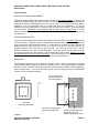
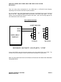
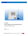
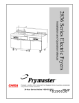
FN:388MAN1.DOC
AEXX-388-X SERIES
MULTI-ZONE
RS232 TIME ZONE CLOCK SYSTEM
(Includes AEXX-354 versions)
AEXX-388-X SERIES, MULTI-ZONE, RS232 TIME ZONE CLOCK SYSTEM
REV 09/18/00
DESCRIPTION
AEXX-388-X Series Multi-Zone Displays are available with 1”, 2.3”, 4”, 8”, or 12” high digits, visible
from 5 feet to 500 feet away. Depending on the digit size, up to 10 zones are possible in a single
enclosure. The maximum length of a single enclosure is 120 inches. For systems requiring
larger displays such as the 8-inch and 12-inch displays, multiple enclosures may be required.
Some systems may have one time zone per enclosure. These models will have a different suffix
(354), but the operation is the same. PC’s or other devices can control the AEXX-388-X Series
Displays by communicating via RS232 using a control program such as 24TZ15.
This manual covers all AE Series Multi-Zone Displays from two to six digits, including two-sided
versions with the RS232 Time Zone Clock System (388) or RS232 Serial Input (354), both can be
set up for fixed addresses or fixed offset operation. It will use the term “the AE DEVICE”, in some
cases to cover all versions of displays.
The model numbers of the AEXX-388-X Series are derived from the digit size and the number of
digits in the display, followed by the 388 suffix and the number of zones included. For example the
AE44-388-2 is a Four-Digit, Four-Inch, Two-Zone Display, and the AE26-388-4 is a 2.3-Inch, SixDigit, Four-Zone Display. For two-sided versions, the model number would have /2. For example:
AE44/2-388-2 would be the model number for a Double-Sided, Four-Inch, Four-Digit, Two-Zone
Display. Each AE Display can be configured in a number of ways. Some will have different
enclosures. For more information on your specific model number refer to the drawings included
at the back of this manual.
A demo disk is available, which contains several sample programs including 24TZ15 for fixed
address. 24TZ15 is a program designed specifically for setting the time on AE Series Time Zone
Clock Systems. Additional, sample programs and detailed programming information are included,
and will aid the user if they wish to create their own control program. See the addendum in the
back of the manual for more information about the 24TZ15 software. Other programs such as
24TIME1 can be used for fixed offset applications.
Name Rails, which are used for the labeling of time zones, are available for the AE Series MultiZone Displays. The Name Rails are built the same length of the clock and increase the height of
the clock by 2.5 inches. Consult the factory for more information on Name Rails on your AE
Display.
For multiple display systems the Master/Driver Option (348) can be added. This option allows you
to connect up to 40 remote displays to the AEXX-388-X Series Display for displaying the same
information in many locations.
APPLIED TECHNICAL SYSTEMS
WWW.ATS-USA.COM
PAGE 1
AEXX-388-X SERIES, MULTI-ZONE, RS232 TIME ZONE CLOCK SYSTEM
REV 09/18/00
SPECIFICATIONS
Digits:
1, 2.3, 4, 8 and 12 Inch High, Seven Segment Digits are available. For
additional digit specifications, see the drawings at the back of this manual
for your specific model.
Function:
Receives control and data information. Modes are provided for sending
ASCII characters and numbers, for setting time of day in 12 or 24-hour
format, and for controlling Up and Down counting elapsed timers.
Time Zone operation - two different formats:
1) Fixed addresses on the rotary switch for specific time zones.
2) Fixed positive or negative offsets from local time are set on the rotary
switch for specific time zones.
Power:
120 VAC – The power required varies with the size and number of digits.
Optional power includes 50 HZ, 12 VAC, 12 to 15 VDC and 220 VAC.
Battery backup: Self-charging, Ni-Cad.
Signal required:
2 wire RS232 (receive only)
2400 baud, no parity, 8 data bits, 1 stop bit.
Enclosure:
Black anodized aluminum with .118" thick red acrylic lens. The back
panel is .125" thick black, ABS plastic. The size varies with the size and
number of digits. See the drawings at the back of this manual.
One or more 1210-0101 mounting brackets are provided for wall
mounting to a single or double gang box. Optional enclosures are
available.
Wiring:
Clearly labeled, pigtail lead wires (#18 AWG) are provided.
terminal blocks, power cords, and connectors are available.
Optional
Program information and drawings are provided at the back of this manual for more detail.
Options:
There are numerous options available Some include: (/2) Two Sided
Version, (348) Master/Driver Output, (376) Relay Output, and (PC8) Add
8 FT. Power Cord. When options are ordered, supplemental information
is provided with addenda and additional drawings.
For all other options refer to the drawings at the back of this manual for additional
specifications.
APPLIED TECHNICAL SYSTEMS
WWW.ATS-USA.COM
PAGE 2
AEXX-388-X SERIES, MULTI-ZONE, RS232 TIME ZONE CLOCK SYSTEM
REV 09/18/00
INSTALLATION
SETTING THE DISPLAY ADDRESSES
Each AEXX-388-X or AEXX-354 display or time zone has its own specific address, so they can be
addressed independently by the users’ program. A rotary switch is provided on each controller for
setting the addresses. Valid addresses are 1 to 15 (1-9, A, B, C, D, E, and F on the rotary switch).
Address 0 is an all call address and is not used with time zone applications. To set the
addresses, the back panel must be removed to gain access to the controller. See the drawings
for more details. Addresses can be specified with the order and set at the factory. If you are
writing your own control program, be sure to include the address in the 10-byte message sent by
the host device.
SETTING FIXED OFFSETS
In this case, each AEXX-388-X or AEXX-354 display or time zone has its own fixed offset from the
time it will be sent. Therefore, they are not addressed independently by the users’ program but all
sent the same time and offset accordingly. A rotary switch is provided on each controller for
setting the offsets. Valid offsets are +/- 1 to 15 (1-9, A, B, C, D, E, and F on the rotary switch). For
negative offsets the S2 input must be tied to ground. The time may only be sent to the AE
Devices via address 0 or 15 (F) for this application. To set the offsets, the back panel must be
removed to gain access to the controller. See the drawings for more details. Offsets (+ or -) can
be specified with the order and set at the factory. If you are writing your own control program, be
sure to include the address in the 10-byte message sent by the host device.
MOUNTING
The AE Series Displays can be mounted in a variety of ways. Things to consider for mounting
include ambient light, viewing area, ambient temperature, dirt or dust. Most models are supplied
with one or more 1210-0101 mounting brackets for wall mounting to a single or double gang box.
See the detail below. For other mounting options, such as ceiling mounts or double-sided
mounts, refer to the specific drawings.
6-32 x ¾ black screw
secures AE Device to
the mounting plate.
1210-0101
mounting plate detail
1210-0101 mounting plate
fastens to the back box.
WIRING
APPLIED TECHNICAL SYSTEMS
WWW.ATS-USA.COM
Single or double gang box
(supplied by others)
Must be securely mounted
PAGE 3
AEXX-388-X SERIES, MULTI-ZONE, RS232 TIME ZONE CLOCK SYSTEM
REV 09/18/00
There are many wiring configurations for the AEXX-388-X or AEXX-354 Series Displays,
depending on the functions used and the options installed.
On most standard units, clearly labeled pigtail leads wires are provided for the power at the back
panel of the unit. Additional pigtail leads are provided for the RS232 Input signal. For other
options, refer to the addendum sheets provided for that option. Also, see the wiring diagrams for
more detail at the back of this manual.
RS232 WIRING DIAGRAM
HOST DEVICE
RCV
COM
AEXX-388-X
DISPLAY
3
5
4
6
8
9 PIN D
2
7
20
6
5
or
25 PIN D
2400 BAUD, NO PARITY, 8 DATA BITS, 1 STOP
Connect the RS232 output from the host computer to the wires labeled "RCV" and "COM". The
connector at the host computer must be wired and have the jumpers as shown above.
SEE THE FOLLOWING SECTION ON THE RS232 OPTION AND THE DEMO DISK PROVIDED
FOR MORE DETAIL.
APPLIED TECHNICAL SYSTEMS
WWW.ATS-USA.COM
PAGE 4
AEXX-388-X SERIES, MULTI-ZONE, RS232 TIME ZONE CLOCK SYSTEM
REV 09/18/00
RS232 TIME ZONE OPTION
DESCRIPTION
The AE Series RS232 Time Zone option allows AE Series devices to communicate with host
computers, process computers (PLC"S), industrial instruments, and other equipment with RS232
output ports. With the 10-byte instruction format multiple units can be connected in parallel and
addressed individually or as a group. Up to 15 unique addresses plus an all call address (0) are
available. The 10-byte instruction also provides mode selection, sends 6 characters, and sets
display attributes. The host computer or controller can have complete control of all the digits and
functions of the AE device with simple or complex programs that can output data via an RS232
serial port.
AE Series devices are available in many configurations with digit sizes of 1", 2", 4", 8", and 12"
high. Systems can be assembled using AE devices of various digit sizes and numbers of digits
and other AE options to meet a variety of time zone applications.
Applications for World Time Zone Clocks include, but are not limited to:
Trading Rooms
Boardrooms and lobbies of Multi-National companies to show time in the various cities where they
have branches, representation or conduct business.
International hotels
Airports
Military installations
APPLIED TECHNICAL SYSTEMS
WWW.ATS-USA.COM
PAGE 5
AEXX-388-X SERIES, MULTI-ZONE, RS232 TIME ZONE CLOCK SYSTEM
REV 09/18/00
OPERATION
Before applying power, be sure all wiring is completed. Apply power to the unit. The displays will
rotate during the power on self-test and then it will flash a version, until data is received. If a
charged battery is installed, the self-test will be bypassed.
If you are using the 24TZ15 control program provided on the Demo disk, see the addendum at the
back of this manual for further instructions. If you will be writing your own control program, you
will need to send the following control information to the AEXX-388-X system.
A 10-byte instruction is required to communicate with the AE Series device. The first byte, byte 0,
is the preamble. It establishes communications with the AE device. The second byte, byte 1, is
the address byte that is used for addressing up to 15 different addresses and an all call address.
Byte 2 is the mode byte. Up to 256 modes are possible providing complete control of all the 7
segment characters and functions of the AE Series products. Bytes 3 through 8 are associated
with the six, 7-segment displays of the AE Series device. Byte 9 is the miscellaneous digit, which
provides attributes such as colons, AM/PM indicators, flash, etc.
BYTE 0:
START CHARACTER - An 11H is required to establish communications.
BYTE 1:
ADDRESS BYTE - Range is from 0 to 15. Used for addressing individual
devices. Address 0 is an ALL CALL address.
Set the address using the Mode Switch (SW1) located on the CPU board.
Switch position 0 is address 0 and switch position F is address 15 for
displays with fixed addresses.
Switch positions 0 – 15 (F) are (+/-) offsets of 0 – 15 (F) as determined
by the configuration for fixed offset displays. Time may only be sent via
address 0 or 15 (F) for displays with fixed offsets.
See the drawing at the back of this manual for more detail.
BYTE 2:
MODE BYTE - Range is from 0 to 255. This byte provides complete
control of all AE Series devices with the RS232 option installed. The
modes are:
MODE O - ASCII character mode. The AE device will display the AE
ASCII characters sent in bytes 3 through 8. See the AE ASCII character
set at the back of this manual.
MODE 1 - Number mode. The AE device will display the numbers 0 to 9
sent in bytes 3 through 8.
MODE 2 - Graphic character mode. The AE device will display the AE
graphic characters sent in bytes 3 through 8. See the AE graphic
character set at the back of this manual.
MODE 3 - 12 Hour Time/timer mode. Bytes 3 through 8 are set as the
time, and time keeping begins.
MODE 4 - 24 Hour Time/timer mode. Bytes 3 through 8 are set as the
time, and time keeping begins.
APPLIED TECHNICAL SYSTEMS
WWW.ATS-USA.COM
PAGE 6
AEXX-388-X SERIES, MULTI-ZONE, RS232 TIME ZONE CLOCK SYSTEM
REV 09/18/00
MODE 5 - Count down timer mode. Bytes 3 through 8 are set as the
preset value to count down from.
MODE 6 - Displays the software version installed in the AE device.
MODE 7 – Presets a Day Counter. Bytes 3 through 8 preset the number
of days to start from. S3 must be tied low and a 1N914 diode must be
installed in the PD8 position on the circuit board assembly. Time is set
using Mode 4. The count is incremented by one everyday at Midnight.
MODES 8 - 255 are for future use.
BYTES 3 - 8:
SIX CHARACTER BYTES - AE devices can have up to 6 digits. The six
characters received are for displaying on these six digits. These
characters will depend on the mode byte, byte 2, that precedes them.
They provide the words for messages, the digits for setting time and
variable, and even 7-segment graphic characters.
BYTE 9:
MISCELLANEOUS DIGIT BYTE - This byte provides colons, AM/PM
indicators, and other attributes such as display flashing.
BIT 0 - Turns on the AM/PM indicator.
BIT 1 - Turns on the colons. Colons are automatically turned on in the
time/timer mode, i.e. byte 2 = 3.
BIT 2 - If equal to 1, stops count down timer. If equal to 0, starts count
down timer.
BIT 3 - If equal to 0, count down timer begins from preset value entered
in bytes 3 through 8. If equal to 1, count down timer begins from where it
previously was stopped.
BIT 7 - Flash display.
APPLIED TECHNICAL SYSTEMS
WWW.ATS-USA.COM
PAGE 7
AEXX-388-X SERIES, MULTI-ZONE, RS232 TIME ZONE CLOCK SYSTEM
REV 09/18/00
TECHNICAL SUPPORT
For any questions concerning installation and operation of this product, contact our factory at:
PHONE (800) 444-7161
OR
FAX (318) 797-4864
SERVICE POLICY
It is recommended that all service for this product be done by the factory or by a factory
authorized service representative. Applied Technical Systems will provide ongoing service
support in and out of warranty. Send your repairs to:
APPLIED TECHNICAL SYSTEMS
815 KING PLACE
SHREVEPORT, LA 71115
APPLIED TECHNICAL SYSTEMS
WARRANTY POLICY
ATS warrants its products to be free of defects in material and workmanship for a period of
24 months from the date of purchase. ATS will repair or replace any product returned to its
authorized factory service center within the warranty period so long as there is no evidence
that the product has been abused, misused, damaged by lightning, overloads of any kind or
water, or altered in any way.
Products returned for warranty must be returned with freight prepaid. ATS will pay normal
freight charges to return the product to the customer. Special premium freight requested by
the customer will be charged to the customer.
ATS disclaims any warranties expressed or implied, including merchantability and/or fitness
for a particular purpose. In no event shall ATS be held liable for incidental or consequential
damages.
APPLIED TECHNICAL SYSTEMS
WWW.ATS-USA.COM
PAGE 8