1
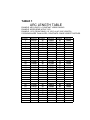
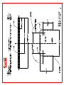
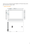
P.O. Box 531 Manitowoc WI 54220
Phone: 920-684-4990 Fax: 920-6843944
Web: Bii1.com
PLEASE FILL OUT AND RETURN IN SELF ADDRESSED ENVELOPE.
COMPANY NAME: ____________________________________________________
ADDRESS: ____________________________________________________
___________________________________________________
TELEPHONE: ____________________________________________________
CONTACT NAME: ____________________________________________________
MACHINE SERIAL NUMBER: _________________________________________
A COPY OF THE INSTRUCTION MANUAL AND WARRANTY HAS BEEN
RECEIVED BY: _____________________________________________________
Signature
_____________________________________________________
Date
INDEXING TABLE
MANUAL
1) Introduction
a) You have made a practical choice in purchasing an RMD, INC. IDX-10
Positioning/Index Table. It has been carefully built of high quality materials and
designed to give many years of efficient service. The simplicity of design and
minimum effort required to operate this attachment contributes towards meeting
schedules and producing greater profits.
b) The IDX-10 Indexing table was designed to allow you to accurately and
repeatedly position distances between bends, by using the adjustable stops. Also
the IDX-10 can be used to hold the material being bent perfectly level while
bending, or altering the angles between bends.
2) Unpacking
a) After receiving the attachment, visually inspect for damage. Any damage should
be reported immediately to Baileigh Industrial.
3) Connection to your machine
a) Remove the shaft mounting bracket [#2] (angle iron) leaving the slide shaft [#16]
in place.
b) Slide the front of the main track tube [#1] onto the slide shaft [#16].
c) Reattach the shaft mounting bracket [#2] and tighten bolts.
d) With the front of the main track tube attached, lift up the rear and support it with a
sturdy saw horse or equal.
e) Attach the rear leg adjuster [#13] using the supplied 3/8 X 1” bolts.
f) Align the keyways with the slide bolt and slip the caster mount [#12] onto the leg
adjuster [#13].
4) Height Adjustment and Leveling
a) Level your machine on a flat hard surface. (The index table must be allowed to
pivot and rotate with the casters.)
b) With the machine level, choose the desired die set.
c) The thickness of the die determines the height of the index table. Using the chart
shown below find the correct number of turns required for your die.
d) Rotate the height adjustment screw [#21] clockwise until it stops. This is the
lowest the table will go. (EXAMPLE 1-1/2 die)
e) Rotate the adjustment screw [#21] counter clockwise the exact number of turns
that were chosen from the chart.
f) Using a 2 ft level placed on the main track tube, rotate the large nut [#35] until the
main track tube is level.
g) Position the front of the main track tube so the center line of the track tube
matches the center (radius) line of the die.
4/22/02
1
5) Material layout
a) Before you can use the IDX table, your first piece of material needs to be laid out.
Using Diagram1 and Table1 you can determine all of the bend start points, these
points should be transferred to the material using a fine point sharpie marker. This
diagram is a generic two bend scenario, for more complex parts the steps are
generally the same.
6) Operation
a) After the connection to your machine is complete, and the height and center line
positions are verified, the IDX-10 can be used.
b) Your first part should now be clearly marked. These marks will be used to
position the tubing perfectly with the “0” mark on the die, and to set your IDX
stops. Only your fist part needs to be marked, after that the IDX stops will be
used.
c) Insert a piece of material through the hook arm of the die being used and insert
through the chuck. (note: If multiple parts are being produced, the material should
be marked so the chuck position can be repeated) position the material so the start
of bend mark lines up with the “0” mark on the die, now set your first stop on the
index table and produce the first bend. NOTE: The complete table will swing, be
sure not to interfere with the motion.
d) After the bend is complete, the die must return to home CAUTION! Make sure
the hook arm of the die does not catch the tubing when returning. Once the
die is home, the material can be advanced and rotated (if required) to the next “0”
mark. The next stop can now be set. Repeat as required, your IDX table comes
standard with (4) stops.
e) The previous steps are just examples how to set stops and produce various bends,
it is up to the user to define exactly how his/her IDX will be set up. Baileigh
Industrial will be glad to offer any suggestions for your application.
HEIGHT ADJUSTMENT
CCW TO RAISE
TURNS CCW DIE THICKNESS
0.0=
1.50
2.5=
2.00
5.0=
2.50
7.5=
3.00
10.0=
3.50
4/22/02
2
WARRANTY & Other Legal Information
Inspection & Acceptance. Buyer shall inspect all Goods within a reasonable period of
time after delivery, not to exceed ten (10) days. If Buyer rejects any Goods, Buyer must
first obtain a Return Authorization Number (“RAN”) before returning any goods to
Seller. Goods returned without a RAN will be refused. Seller will not be responsible for
any freight costs, damages to goods, or any other costs or liabilities pertaining to goods
returned without a RAN. Seller shall have the right to substitute a conforming tender.
Buyer will be responsible for all freight costs to and from Buyer and repackaging costs, if
any, if Buyer refuses to accept shipment. If Goods are returned in unsaleable condition,
Buyer shall be responsible for full value of the Goods. Buyer may not return any special
order Goods. Any Goods returned hereunder shall be subject to a restocking fee equal to
30% of the invoice price.
Specifications. Seller may, at its option, make changes in the designs, specifications or
components of the Goods to improve the safety of such Goods, or if in Seller’s judgment,
such changes will be beneficial to their operation or use. Buyer may not make any
changes in the specifications for the Goods unless Seller approves of such changes in
writing, in which event Seller may impose additional charges to implement such changes.
Limited Warranty. Seller warrants to the original end-user that the Goods manufactured
or provided by Seller under this Agreement shall be free of defects in material or
workmanship for a period of twelve (12) months from the date of purchase, provided that
the Goods are installed, used, and maintained in accordance with any instruction manual
or technical guidelines provided by the Seller or supplied with the Goods, if applicable.
The original end-user must give written notice to Seller of any suspected defect in the
Goods prior to the expiration of the warranty period. The original end-user must also
obtain a RAN from Seller prior to returning any Goods to Seller for warranty service
under this paragraph. Seller will not accept any responsibility for Goods returned without
a RAN. The original end-user shall be responsible for all costs and expenses associated
with returning the Goods to Seller for warranty service. In the event of a
defect, Seller, at its sole option, shall repair or replace the defective Goods or refund to
the original end-user the purchase price for such defective Goods. The foregoing
warranty is Seller’s sole obligation, and the original end-user’s exclusive remedy, with
regard to any defective Goods. This limited warranty does not apply to: (a) die sets,
tooling, and saw blades; (b) periodic or routine maintenance and setup, (c) repair or
replacement of the Goods due to normal wear and tear, (d) defects or damage to the
Goods resulting from misuse, abuse, neglect, or accidents, (f) defects or damage to the
Goods resulting from improper or unauthorized alterations, modifications, or changes;
and (f) any Goods that has not been installed and/or maintained in accordance with the
instruction manual or technical guidelines provided by Seller.
EXCLUSION OF OTHER WARRANTIES. THE FOREGOING LIMITED
WARRANTY IS IN LIEU OF ALL OTHER WARRANTIES, EXPRESS OR IMPLIED.
ANY AND ALL OTHER EXPRESS, STATUTORY OR IMPLIED WARRANTIES,
INCLUDING BUT NOT LIMITED TO, ANY WARRANTY OF
MERCHANTABILITY OR FITNESS FOR ANY PARTICULAR PURPOSE ARE
EXPRESSLY DISCLAIMED. NO WARRANTY IS MADE WHICH EXTENDS
BEYOND THAT WHICH IS EXPRESSLY CONTAINED HEREIN.
LIMITATION OF LIABILITY. IN NO EVENT SHALL SELLER BE LIABLE TO
BUYER OR ANY OTHER PARTY FOR ANY INCIDENTIAL, CONSEQUENTIAL
OR SPECIAL DAMAGES (INCLUDING, WITHOUT LIMITATION, LOST PROFITS
OR DOWN TIME) ARISING FROM OR IN MANNER CONNECTED WITH THE
GOODS, ANY BREACH BY SELLER OR ITS AGENTS OF THIS AGREEMENT, OR
ANY OTHER CAUSE WHATSOEVER, WHETHER BASED ON CONTRACT, TORT
OR ANY OTHER THEORY OF LIABILITY. BUYER’S REMEDY WITH
RESPECT TO ANY CLAIM ARISING UNDER THIS AGREEMENT IS STRICTLY
LIMITED TO NO MORE THAN THE AMOUNT PAID BY THE BUYER FOR THE
GOODS.
Force Majuere. Seller shall not be responsible for any delay in the delivery of, or failure
to deliver, Goods due to causes beyond Seller’s reasonable control including, without
limitation, acts of God, acts of war or terrorism, enemy actions, hostilities, strikes, labor
difficulties, embargoes, non-delivery or late delivery of materials, parts and equipment or
transportation delays not caused by the fault of Seller, delays caused by civil authorities,
governmental regulations or
orders, fire, lightening, natural disasters or any other cause beyond Seller's reasonable
control. In the event of any such delay, performance will be postponed by such length of
time as may be reasonably necessary to compensate for the delay.
Installation. If Buyer purchases any Goods that require installation, Buyer shall, at its
expense, make all arrangements and connections necessary to install and operate the
Goods. Buyer shall install the Goods in accordance with any Seller instructions and shall
indemnify Seller against any and all damages, demands, suits, causes of action, claims
and expenses (including actual attorneys’ fees and costs) arising directly or indirectly out
of Buyer’s failure to properly install the Goods.
Work By Others; Safety Devices. Unless agreed to in writing by Seller, Seller has no
responsibility for labor or work performed by Buyer or others, of any nature, relating to
design, manufacture, fabrication, use, installation or provision of Goods. Buyer is solely
responsible for furnishing, and requiring its employees and customers to use all safety
devices, guards and safe operating procedures required by law and/or as set forth in
manuals and instruction sheets furnished by Seller. Buyer is responsible for consulting all
operator’s manuals, ANSI or comparable safety standards, OSHA regulations and other
sources of safety standards and regulations applicable to the use and operation of the
Goods.
Remedies. Each of the rights and remedies of Seller under this Agreement is cumulative
and in addition to any other or further remedies provided under this Agreement or at law
or equity.
Attorney’s Fees. In the event legal action is necessary to recover monies due from Buyer
or to enforce any provision of this Agreement, Buyer shall be liable to Seller for all costs
and expenses associated therewith, including Seller’s actual attorneys' fees
and costs.
Governing Law/Venue. This Agreement shall be construed and governed under the laws
of the State of Wisconsin, without application of conflict of law principles. Each party
agrees that all actions or proceedings arising out of or in connection with this Agreement
shall be commenced, tried, and litigated only in the state courts sitting in Manitowoc
County, Wisconsin or the U.S. Federal Court for the Eastern District of Wisconsin. Each
party waives any right it may have to assert the doctrine of “forum non conveniens” or to
object to venue to the extent that any proceeding is brought in accordance with this
section. Each party consents to and waives any objection to the exercise of personal
jurisdiction over it by courts described in this section. EACH PARTY WAIVES TO THE
FULLEST EXTENT PERMITTED BY APPLICABLE LAW THE RIGHT TO A TRIAL
BY JURY.
TABLE 1
ARC LENGTH TABLE
EXAMPLE: ARC LENGTH = CONSTANT X BEND RADIUS
EXAMPLE: 90DEG BEND WITH 6" CLR
EXAMPLE: 1.575 (FROM TABLE) X 6" (CLR) =9.45" (ARC LENGTH)
FOR BENDS MORE THAN 90 DEG, CONSTANTS CAN BE ADDED TOGETHER
DEGREES
1
2
3
4
5
6
7
8
9
10
11
12
13
14
15
16
17
18
19
20
21
22
23
24
25
26
27
28
29
30
CONSTANT
0.0175
0.0349
0.0524
0.0698
0.0873
0.1047
0.1222
0.1396
0.1571
0.1745
0.1920
0.2094
0.2269
0.2443
0.2618
0.2792
0.2967
0.3141
0.3316
0.3490
0.3665
0.3839
0.4014
0.4188
0.4363
0.4537
0.4712
0.4886
0.5061
0.5235
DEGREES
31
32
33
34
35
36
37
38
39
40
41
42
43
44
45
46
47
48
49
50
51
52
53
54
55
56
57
58
59
60
CONSTANT
0.5410
0.5584
0.5759
0.5933
0.6108
0.6282
0.6457
0.6631
0.6806
0.6980
0.7155
0.7329
0.7504
0.7678
0.7853
0.8027
0.8202
0.8376
0.8551
0.8725
0.8900
0.9074
0.9249
0.9423
0.9598
0.9772
0.9947
1.0121
1.0296
1.0470
DEGREES
61
62
63
64
65
66
67
68
69
70
71
72
73
74
75
76
77
78
79
80
81
82
83
84
85
86
87
88
89
90
CONSTANT
1.0645
1.0819
1.0994
1.1168
1.1343
1.1517
1.1692
1.1866
1.2041
1.2215
1.2390
1.2564
1.2739
1.2913
1.3088
1.3262
1.3437
1.3611
1.3786
1.3960
1.4135
1.4309
1.4484
1.4658
1.4833
1.5007
1.5182
1.5356
1.5531
1.5705