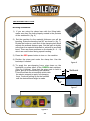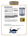
1
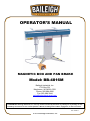
OPERATOR’S MANUAL
MAGNETIC BOX AND PAN BRAKE
Model: BB-4816M
Baileigh Industrial, Inc.
P.O. Box 531
Manitowoc, WI 54221-0531
Phone: 920.684.4990
Fax: 920.684.3944
[email protected]
REPRODUCTION OF THIS MANUAL IN ANY FORM WITHOUT WRITTEN APPROVAL OF BAILEIGH INDUSTRIAL, INC.
IS PROHIBITED. Baileigh Industrial, Inc. does not assume and hereby disclaims any liability for any damage or loss
caused by an omission or error in this Operator’s Manual, resulting from accident, negligence, or other occurence.
Rev. 02/2014
1 Industrial, Inc.
© 2014 Baileigh
TABLE OF CONTENTS
THANK YOU AND WARRANTY ............................................................................................... 3, 4, 5
INTRODUCTION / DESCRIPTION / GENERAL NOTES .......................................................... 6
SAFETY INSTRUCTIONS ......................................................................................................... 7, 8
SAFETY PRECAUTIONS .......................................................................................................... 9, 10
TECHNICAL SPECIFICATIONS ............................................................................................... 11
MACHINE FEATURES .............................................................................................................. 11
OVERALL DIMENSIONS .......................................................................................................... 12
TRANSPORTING AND LIFTING ............................................................................................... 13
UNPACKING AND CHECKING CONTENTS............................................................................ 14, 15
Cleaning ................................................................................................................................ 16
MAGNETIC BRAKE ASSEMBLY ............................................................................................. 17
Attaching the Legs ................................................................................................................. 17
Tool Tray and Back gauge Supports ..................................................................................... 17
Footswitch ............................................................................................................................. 17
INSTALLATION ......................................................................................................................... 18
Leveling ................................................................................................................................. 18
THE OPERATION CYCLE......................................................................................................... 19, 20, 21, 22
Bending Sheet metal ............................................................................................................. 19, 20
Bending Thicker Materials ..................................................................................................... 20
Bending Allowance ................................................................................................................ 21
Bend Configurations .............................................................................................................. 21
Understanding Springback .................................................................................................... 22
MATERIAL SELECTION ........................................................................................................... 22
BENDING EXAMPLES .............................................................................................................. 23, 24
Folding Over a Lip ................................................................................................................. 23
Rolling the Edge .................................................................................................................... 23
Making a Box With Clamping Bars ........................................................................................ 24
Forming Pans With Slotted Clamp Bar ................................................................................. 24
LUBRICATION, MAINTENANCE, and ADJUSTMENTS ......................................................... 25, 26
Checking Machine Accuracy ................................................................................................. 26
Checking the Gap .................................................................................................................. 26
ELECTRICAL ENCLOSURE ..................................................................................................... 27
ELECTRICAL SCHEMATIC ...................................................................................................... 28
PARTS LIST............................................................................................................................... 29
PARTS IDENTIFICATION DRAWING ....................................................................................... 30
TROUBLESHOOTING .............................................................................................................. 31
Full Clamping Malfunction ..................................................................................................... 31
MACHINE ACKNOWLEGEMENT ............................................................................................. 33
2
THANK YOU & WARRANTY
1. Thank you for your purchase of a Baileigh Industrial Magnetic Box and Pan Brake. We hope that
you find it productive and useful to you for a long time to come.
2. Inspection & Acceptance. Buyer shall inspect all Goods within a reasonable period of time after
delivery, not to exceed ten (10) days. If Buyer rejects any Goods, Buyer must first obtain a Return
Authorization Number (“RAN”) before returning any goods to Seller. Goods returned without a
RAN will be refused. Seller will not be responsible for any freight costs, damages to goods, or any
other costs or liabilities pertaining to goods returned without a RAN. Seller shall have the right to
substitute a conforming tender. Buyer will be responsible for all freight costs to and from Buyer
and repackaging costs, if any, if Buyer refuses to accept shipment. If Goods are returned in
unsaleable condition, Buyer shall be responsible for full value of the Goods. Buyer may not return
any special order Goods. Any Goods returned hereunder shall be subject to a restocking fee equal
to 30% of the invoice price.
3. Specifications. Seller may, at its option, make changes in the designs, specifications or
components of the Goods to improve the safety of such Goods, or if in Seller’s judgment, such
changes will be beneficial to their operation or use. Buyer may not make any changes in the
specifications for the Goods unless Seller approves of such changes in writing, in which event
Seller may impose additional charges to implement such changes.
4. Limited Warranty. Seller warrants to the original end-user that the Goods manufactured or
provided by Seller under this Agreement shall be free of defects in material or workmanship for a
period of twelve (12) months from the date of purchase, provided that the Goods are installed, used,
and maintained in accordance with any instruction manual or technical guidelines provided by the
Seller or supplied with the Goods, if applicable. The original end-user must give written notice to
Seller of any suspected defect in the Goods prior to the expiration of the warranty period. The
original end-user must also obtain a RAN from Seller prior to returning any Goods to Seller for
warranty service under this paragraph. Seller will not accept any responsibility for Goods returned
without a RAN. The original end-user shall be responsible for all costs and expenses associated
with returning the Goods to Seller for warranty service. In the event of a defect, Seller, at its sole
option, shall repair or replace the defective Goods or refund to the original end-user the purchase
price for such defective Goods. The foregoing warranty is Seller’s sole obligation, and the original
end-user’s exclusive remedy, with regard to any defective Goods. This limited warranty does not
apply to: (a) die sets, tooling, and saw blades; (b) periodic or routine maintenance and setup, (c)
repair or replacement of the Goods due to normal wear and tear, (d) defects or damage to the Goods
resulting from misuse, abuse, neglect, or accidents, (f) defects or damage to the Goods resulting
from improper or unauthorized alterations, modifications, or changes; and (f) any Goods that has
not been installed and/or maintained in accordance with the instruction manual or technical
guidelines provided by Seller.
3
5. EXCLUSION OF OTHER WARRANTIES. THE FOREGOING LIMITED WARRANTY IS
IN LIEU OF ALL OTHER WARRANTIES, EXPRESS OR IMPLIED. ANY AND ALL OTHER
EXPRESS, STATUTORY OR IMPLIED WARRANTIES, INCLUDING BUT NOT LIMITED
TO, ANY WARRANTY OF MERCHANTABILITY OR FITNESS FOR ANY PARTICULAR
PURPOSE ARE EXPRESSLY DISCLAIMED. NO WARRANTY IS MADE WHICH EXTENDS
BEYOND THAT WHICH IS EXPRESSLY CONTAINED HEREIN.
6. LIMITATION OF LIABILITY. IN NO EVENT SHALL SELLER BE LIABLE TO BUYER
OR ANY OTHER PARTY FOR ANY INCIDENTIAL, CONSEQUENTIAL OR SPECIAL
DAMAGES (INCLUDING, WITHOUT LIMITATION, LOST PROFITS OR DOWN TIME)
ARISING FROM OR IN MANNER CONNECTED WITH THE GOODS, ANY BREACH BY
SELLER OR ITS AGENTS OF THIS AGREEMENT, OR ANY OTHER CAUSE
WHATSOEVER, WHETHER BASED ON CONTRACT, TORT OR ANY OTHER THEORY OF
LIABILITY. BUYER’S REMEDY WITH
RESPECT TO ANY CLAIM ARISING UNDER THIS AGREEMENT IS STRICTLY LIMITED
TO NO MORE THAN THE AMOUNT PAID BY THE BUYER FOR THE GOODS.
7. Force Majuere. Seller shall not be responsible for any delay in the delivery of, or failure to
deliver, Goods due to causes beyond Seller’s reasonable control including, without limitation, acts
of God, acts of war or terrorism, enemy actions, hostilities, strikes, labor difficulties, embargoes,
non-delivery or late delivery of materials, parts and equipment or transportation delays not caused
by the fault of Seller, delays caused by civil authorities, governmental regulations or
orders, fire, lightening, natural disasters or any other cause beyond Seller's reasonable control. In
the event of any such delay, performance will be postponed by such length of time as may be
reasonably necessary to compensate for the delay.
8. Installation. If Buyer purchases any Goods that require installation, Buyer shall, at its expense,
make all arrangements and connections necessary to install and operate the Goods. Buyer shall
install the Goods in accordance with any Seller instructions and shall indemnify Seller against any
and all damages, demands, suits, causes of action, claims and expenses (including actual attorneys’
fees and costs) arising directly or indirectly out of Buyer’s failure to properly install the Goods.
9. Work By Others; Safety Devices. Unless agreed to in writing by Seller, Seller has no
responsibility for labor or work performed by Buyer or others, of any nature, relating to design,
manufacture, fabrication, use, installation or provision of Goods. Buyer is solely responsible for
furnishing, and requiring its employees and customers to use all safety devices, guards and safe
operating procedures required by law and/or as set forth in manuals and instruction sheets furnished
by Seller. Buyer is responsible for consulting all operator’s manuals, ANSI or comparable safety
standards, OSHA regulations and other sources of safety standards and regulations applicable to the
use and operation of the Goods.
10. Remedies. Each of the rights and remedies of Seller under this Agreement is cumulative and in
addition to any other or further remedies provided under this Agreement or at law or equity.
4
11. Attorney’s Fees. In the event legal action is necessary to recover monies due from Buyer or to
enforce any provision of this Agreement, Buyer shall be liable to Seller for all costs and expenses
associated therewith, including Seller’s actual attorneys' fees
and costs.
12. Governing Law/Venue. This Agreement shall be construed and governed under the laws of the
State of Wisconsin, without application of conflict of law principles. Each party agrees that all
actions or proceedings arising out of or in connection with this Agreement shall be commenced,
tried, and litigated only in the state courts sitting in Manitowoc County, Wisconsin or the U.S.
Federal Court for the Eastern District of Wisconsin. Each party waives any right it may have to
assert the doctrine of “forum non conveniens” or to object to venue to the extent that any
proceeding is brought in accordance with this section. Each party consents to and waives any
objection to the exercise of personal jurisdiction over it by courts described in this section. EACH
PARTY WAIVES TO THE FULLEST EXTENT PERMITTED BY APPLICABLE LAW THE
RIGHT TO A TRIAL BY JURY.
5
INTRODUCTION
The quality and reliability of the components assembled on a Baileigh Industrial machine
guarantee near perfect functioning, free from problems, even under the most demanding
working conditions. However if a situation arises, refer to the manual first. If a solution cannot be
found, contact the distributor where you purchased our product. Make sure you have the serial
number and production year of the machine. (stamped on the nameplate). For replacement
parts refer to the assembly numbers on the parts list drawings.
Our technical staff will do their best to help you get your machine back in working order.
DESCRIPTION
The Baileigh Model BB-4816M is a unique magnetic box and pan brake with endless bending
possibilities, as compared to a conventional sheet metal brake. A powerful electro-magnet in
the bending bed, engaged by either pushbutton or foot pedal, holds down a mild steel
clamping bar to the bed. The piece part is held between this clamping bar and the bed while
the bending leaf is lifted to complete the bend.
The brake comes with an assortment of clamping bars to handle a variety of bending
configurations. It can bend items, which are impossible on a traditional box and pan brake,
such as totally enclosed boxes, triangles, alternate bends on varying planes, round items as
in scrolling applications, and many more.
One of the advantages to this type of box and pan brake is that the magnetic power of 6 tons
is consistent across the entire beam, allowing for very crisp bends, even in the middle of the
machine. This machine is perfect for bending sheets of mild steel, stainless steel, aluminum,
coated materials, heated plastics, and more.
In this manual you will find: (when applicable)
• Safety procedures, Installation guidelines, Capacity charts
• Description of the functional parts of the machine
• Set-up and start-up instructions, Machine operation
• Scheduled maintenance, Parts lists
GENERAL NOTES
After receiving your equipment remove the protective container. Do a complete visual
inspection, and if damage is noted, photograph it for insurance claims and contact your
carrier at once, requesting inspection. Also contact Baileigh Industrial and inform them of the
unexpected occurrence. Temporarily suspend installation.
Following proper maintenance instructions will help ensure your machine will work smoothly
and efficiently. Try and use original spare parts, whenever possible, and most importantly;
DO NOT overload the machine or make any unauthorized modifications.
Note: This symbol refers to useful information throughout the manual.
6
PLEASE READ THIS OPERATORS MANUAL CAREFULLY
It contains important safety information, instructions, and necessary operating
procedures. The continual observance of these procedures will help increase
your production and extend the life of the equipment.
SAFETY INSTRUCTIONS
LEARN TO RECOGNIZE SAFETY INFORMATION
This is the safety alert symbol. When you see this
symbol on your machine or in this manual, BE ALERT
TO THE POTENTIAL FOR PERSONAL INJURY!
Follow recommended precautions and safe operating
practices.
UNDERSTAND SIGNAL WORDS
A signal word – DANGER, WARNING, or CAUTION is
used with the safety alert symbol. DANGER identifies
a hazard or unsafe practice that will result in severe
Injury or Death.
Safety signs with signal word DANGER or WARNING
are typically near specific hazards.
General precautions are listed on CAUTION safety
signs CAUTION also calls attention to safety
messages in this manual.
7
PROTECT EYES
Wear safety glasses or suitable eye protection when
working on or around machinery.
BEWARE OF CRUSH HAZARD
Placing fingers or hands between the clamping leaf and
the magnetic bed could cause serious personal injury.
NEVER place any part of your body in the bending
mechanism of the machine.
HIGH VOLTAGE
USE CAUTION IN HIGH VOLTAGE AREAS.
DO NOT assume the power to be off.
MAKE SURE PROPER LOCKOUT
PROCEDURES ARE FOLLOWED.
PROTECT AGAINST NOISE
Prolonged exposure to loud noise can cause impairment
or loss of hearing. Wear suitable hearing protective
devices such as ear muffs or earplugs to protect against
objectionable or uncomfortable loud noises.
8
SAFETY PRECAUTIONS
1. Using Lift equipment.
lighting, etc.
Be careful not to touch overhead power lines, piping,
2. Remove any adjusting tools. Before operating the machine make sure any
adjusting tools have been removed.
3. Keep work area clean. Cluttered areas invite injuries.
4. Overloading Brake. By overloading the brake you may cause injury from flying
parts. DO NOT exceed the specified machine capacities.
5. Machine usage. DO NOT use the brake as a press or crushing tool.
6. Dressing material edges. Before bending sheet metal, always chamfer and deburr
all sharp edges.
7. Do not force tool. Your machine will do a better and safer job if used as intended.
DO NOT use inappropriate attachments in an attempt to exceed the machines
rated capacity.
8. Use the right tool for the job. DO NOT attempt to force a small tool or attachment
to do the work of a large industrial tool. DO NOT use a tool for a purpose for which
it was not intended.
9. Dress appropriate. DO NOT wear loose fitting clothing or jewelry as they can be
caught in moving machine parts. Protective clothing and steel toe shoes are
recommended when using machinery. Wear a restrictive hair covering to contain
long hair.
10. Use eye and ear protection. Always wear ISO approved impact safety goggles.
Wear a full-face shield if you are producing metal filings.
11. Do not overreach. Maintain proper footing and balance at all times. DO NOT reach
over or across a running machine.
12. Stay alert. Watch what you are doing and use common sense. DO NOT operate
any tool or machine when you are tired.
9
SAFETY PRECAUTIONS (cont.)
13. Check for damaged parts. Before using any tool or machine, carefully check any
part that appears damaged. Check for alignment and binding of moving parts that
may affect proper machine operation.
14. Observe work area conditions. DO NOT use machines or power tools in damp
or wet locations. Do not expose to rain. Keep work area well lighted. DO NOT use
electrically powered tools in the presence of flammable gases or liquids.
15. Keep children away. Children must never be allowed in the work area. DO NOT
let them handle machines, tools , or extension cords.
16. Store idle equipment. When not in use, tools must be stored in a dry location to
inhibit rust. Always lock up tools and keep them out of reach of children.
17. Do not operate machine if under the influence of alcohol or drugs. Read
warning labels on prescriptions. If there is any doubt, DO NOT operate the
machine.
18. Bolt machine to sturdy level floor. This will prevent machine from slipping and
possibly tipping over.
10
TECHNICAL SPECIFICATIONS
48"
16 ga. (M.S.) 20 ga. (SSTL)
6 Tons
2 Pc. Welded Steel
220V, Single Phase, 60Hz
12 Amps
Unlimited
57" / 44" / 15"
462 Lbs.
Bend Length
Bend Material Thickness
Clamping Force
Floor Stand
Electrical
Amp Draw
Box Depth
Shipping Dimensions (L / W / H)
Shipping Weight
MACHINE FEATURES
•
•
•
•
•
•
•
•
•
Bends metal and more
Handy lined tool tray
Dual pushbuttons or footswitch to energize electro-magnet
Easy to use gap adjustment knobs on long clamp bars
Scaled angle control for repeatable bends
Sturdy four legged base
Adjustable back gauges for production runs
Spring loaded locating balls to position long clamp bars
3-Hinged bending leaf for strength and reliability
Note: The specifications and dimensions presented here are subject to
change without prior notice due to improvements of our products.
11
OVERALL DIMENSIONS
figure 1
12
TRANSPORTING AND LIFTING
WARNING: Lifting and carrying operations should be carried out by skilled
workers, such as a truck operator, crane operator, etc. If a crane is used to lift the
machine, attach the lifting straps carefully, making sure the magnetic brake is well
balanced. Choose a location that will keep the brake free from vibration and dust
from other machinery. Keep in mind that having a large clearance area around the
machine is important for safe and efficient working conditions.
462 lbs.
When transporting in
its own packaging, use
a forklift truck or hand
trolley.
figure 2
Your Baileigh BB-4816M Magnetic Box and Pan Brake is shipped complete in
one crate.
1) When lifting the assembled machine, make sure the weight is supported
evenly with a minimum of two straps, each capable of lifting 500 lbs.
(Make sure the body of the brake is bearing the load.)
2) Lift the machine carefully, avoiding sudden accelerations or quick changes
of direction.
13
UNPACKING AND CHECKING CONTENTS
Separate all parts from the packing material and check each item carefully.
Make certain all items are accounted for before discarding any packing material.
2
3
1
4
14
UNPACKING AND CHECKING CONTENTS (cont.)
7
5
6
8b
8a
8c
8d
8e
Item
1
2
3
4
5
6
7
8a
8b
8c
8d
8e
9
Name
Body and Pedestal
Footswitch
Back Feet
Front Feet
Tool Tray
Back Stop Collars
Back Stop Bars
Notched Clamp Bar - Long
Narrow Clamp Bar
Wide Clamp Bar - Long
Wide Clamp Bar - Short
Segmented Clamp Bar (Assortment)
Bag of Hardware
15
Qty.
1
1
2
2
1
2
2
1
1
1
1
1
1
Cleaning
Your machine may be shipped with a rustproof waxy oil coating and grease on the
exposed unpainted metal surfaces. To remove this protective coating use a
degreaser or solvent cleaner. For a more thorough cleaning, some parts will
occasionally have to be removed. DO NOT USE acetone or brake cleaner as they
may damage painted surfaces. Follow manufacturer’s label instructions when
using any type of cleaning product. After cleaning, wipe unpainted metal surfaces
with a light coating of quality oil or grease for protection.
WARNING
DO NOT USE gasoline or other petroleum products to clean
the machine. They have low flash points and can explode or
cause fire.
GAS
CAUTION
When using cleaning solvents work in a well ventilated area.
Many cleaning solvents are toxic if inhaled.
16
MAGNETIC BRAKE ASSEMBLY
Attaching the Legs
With the help of another individual,
raise the support column to a vertical
position as shown in (fig. 3). Attach
each foot with (2) M10x16 button head
screws (provided). The two feet with
the safety tape will be on the front of
the brake. (the side with the Baileigh
logo) Tighten the button head screws
securely. Carefully lay the brake on its
side and then place in an upright
position with a suitable lifting device.
figure 3
Backgauge collar
Tool Tray and Backgauge Supports
Using (3) M8x12 socket cap screws
attach the tool tray to the back of the
brake. Lay the rubber mat into the tray.
Attach each backgauge bar to the brake
with (2) M8x16 socket capscrews.
Tighten securely. Slide a backgauge
collar onto each bar as shown in (fig. 4).
Tool tray
Backgauge
support
figure 4
Footswitch
Unstrap and straighten out
the footswitch cable. Grasp
the connector end and plug
into the receptacle at the
back of the machine. Tighten
the connector sleeve.
figure 5
17
INSTALLATION
ATTENTION: HAVE ELECTRICAL UTILITIES CONNECTED TO MACHINE
BY A CERTIFIED ELECTRICIAN !
Check if the available power supply is the same as required by the magnetic
brake (consult nameplate on machine base)
Make sure the grounding wire (green) is properly connected to avoid electric
shock. DO NOT switch the position of the green grounding wire if any electrical
plug wires are switched during hookup.
WARNING
Leveling
The machine should be sited on a level, concrete floor and adequately secured.
The accuracy of any machine depends on the precise placement of it to the
mounting surface.
IMPORTANT:
• Maintain an adequate working area around the machine for safety.
• Have the work area well illuminated with proper lighting.
• Remove scrap and waste materials regularly, and make sure the work area is
free from obstructing objects.
• Keep the floor free of oil and make sure it is not slippery.
• If long lengths of material are to be fed into the machine, make sure that they
will not extend into any aisles.
THE OPERATION CYCLE
Note:
DO NOT run the magnetic brake without material between the clamping bar
and the electromagnetic work bench. After releasing the electromagnet,
residual magnetism could still hold down the clamp bar.
18
THE OPERATION CYCLE
Bending Sheetmetal
1) If you are using the clamp bars with the lifting balls,
make sure they are both properly seated in the pockets
of the workbench. (fig. 6)
2) Set the machine for the material thickness you will be
bending. Raise the bending leaf 90° as shown in (fig. 7).
Rotate the knobs on each end of the clamping bar which
adjusts the setback distance gap. Set this gap at slightly
more than the material thickness to achieve an accurate
bend. There are three positions on the knobs (0 – 1 – 2)
which are useful when doing repeat bending.
3) Press the RED power button to turn on the machine.
4) Position the piece part under the clamp bar. Use the
backstop if needed.
5) To apply the pre-clamping force, step down on the
footswitch or press either of the GREEN start switches.
(See fig. 8 below) Now that the piece part is held in
place, pull up on the bending leaf handles.
This will activate the microswitch which tells
the electro-magnet to apply full clamping
force. Continue pulling up on the handles
until the desired bend angle is made.
figure 6
Setback
90°
figure 7
figure 8
19
THE OPERATION CYCLE (cont.)
6) The left handle has a leaf angle indicator that is
shown in (fig. 9). To allow for springback of the
material, bend a few degrees more than the
required angle. Read the section Understanding
springback on page 22. There is also a locking
collar on the indicating shaft which can be set and
locked to duplicate multiple bends.
7) After the bend is made, lower the bending leaf.
Press and hold IN the RED stop button (fig. 10)
until the clamping bar releases and raises up.
Immediately let go of the button. (Every time the
machine switches OFF, a short pulse of reverse
current
is sent through the electromagnet to
demagnetize it as well as the piece part.)
figure 9
8) Reposition the piece part for the next bend and
repeat steps 4 thru 7.
9) For thicker gauge materials set the toggle switch in
(fig. 10) to the CLAMPING FOR BENDING position.
When bending very thin materials set the toggle
switch to CONTINUOUS LIGHT CLAMPING.
figure 10
Bending Thicker Materials
When bending a narrow lip on a thicker piece of material it is a good idea to place
a piece of filler material under the clamping bar as shown in (fig. 11).
Piece part
Piece of filler
material
figure 11
20
THE OPERATION CYCLE (cont.)
Bending Allowance
In order to bend sheet metal accurately, you will need to consider the total length of
each bend. This is referred to as bend allowance. Subtract the bend allowance
from the sum of the outside dimensions of the piece part to obtain the actual overall
length or width of the piece. Because of differences in sheet metal hardness, and
whether the bend is made with the grain or against it, exact allowances must
sometimes be made by trial and error. However bend allowances for general use
can be obtained from metal working books or from the Internet.
WARNING:
The bending brake poses a pinching hazard. Make
sure no body part or clothing comes between the clamping bar and
the bending leaf.
CAUTION:
Always wear proper eye protection with side shields, steel toe
footwear, and leather gloves to protect from burrs and sharp edges.
Bend Configurations
Return Bends
Rolled Edge
Box
Hem
Stiffening Rib
Closed Channel
Angle Bend
21
Fins
THE OPERATION CYCLE (cont.)
CAUTION: If handling large heavy sheets make sure they are
properly supported
Understanding Spring back
Spring back, also known as elastic recovery, is the result of the metal wanting
to return to its original shape after undergoing compression and stretch. After
the bending leaf is removed from the metal and the load is released, the
piece part relaxes, forcing the bent portion of the metal to return slightly to its
original shape. The key to obtaining the correct bend angle is to over bend
the metal a little and allow it to spring back to the desired angle. All metals
exhibit a certain amount of spring back.
CAUTION: It must be determined by the customer that materials being processed
through the machine are NOT potentially hazardous to operator or personnel
working nearby.
When selecting materials keep these instructions in mind:
• Material must be clean and dry. ( without oil )
• Material should have a smooth surface so it processes easily.
• Dimensional properties of material must be consistent and not exceed the
machine capacity values.
• Chemical structure of material must be consistant.
• Buy certificated steel from the same vendor when possible.
TECHNICAL SUPPORT
Our technical support department can be reached at 920.684.4990, and asking for the
support desk for purchased machines. Tech Support handles questions on machine
setup, schematics, warranty issues, and individual parts needs: (other than die sets and
blades)
For specific application needs or future machine purchases contact the Sales Department.
at: [email protected] or phone: 920.684.4990
22
BENDING EXAMPLES
Folding Over a Lip
The thickness, width, and length of material
are factors to consider when folding a lip. DO
NOT exceed 20ga. (.035”) for material
thickness.
1) With the clamping bar in place and
properly secured, bend the material as
far as the bending leaf will allow. (Normal
bending procedure)
figure 12
2) Now remove the clamping bar, bring up
the bending leaf, and continue the fold as
in (fig. 12). (No clamping is required.)
4) To further flatten the material, slide the
piece part forward about 1/2” and use the
bar to magnetically clamp it as shown in
(fig. 13)
figure 13
Rolling the edge
Use a piece of solid steel round or a pipe to
accomplish this.
1) Position the clamping bar and the round
bar as in (fig. 14) to ensure that the piece
part is positioned correctly. Energize the
electromagnet.
figure 14
2) Raise the bending leaf to make the initial
bend.
3) Release the electromagnet and rotate the
piece part down to the horizontal position.
4) Continue the above procedure until you
are satisfied with the result.
figure 15
23
BENDING EXAMPLES (cont.)
Making a Box With Clamping Bars
1) Using a long clamp bar, initiate the first two bends.
2) Choose and insert one or more of the short clamp bars as shown in (fig. 16)
below for the opposite bends. (This method allows for deep depth boxes.)
3) Clamping bars can be layed side by side or pinned together for repeat bending
of multiple units.
figure 16
Forming Pans With Slotted Clamp Bar
The slotted clamp bar works great for making shallow pans and trays. The entire
clamp bar lifts automatically for easy insertion and removal of the piece part.
1) Fold two opposite sides and the corner tabs with the slotted clamp bar. (The
slots will NOT affect these bends.)
2) Select two slots that fit the pan for the remaining bends. The edge of the tray
should be under the clamp bar and between the selected slots.
figure 17
24
LUBRICATION, MAINTENANCE, and ADJUSTMENTS
MAINTENANCE SHOULD BE PERFORMED ON A REGULAR BASIS
BY QUALIFIED PERSONNEL
WARNING: Always follow proper safety precautions when working
around machinery
•
•
•
•
•
Check daily for any unsafe conditions and fix immediately.
Check that all nuts and bolts are properly tightened.
On a weekly basis clean the machine and the area around it.
Keep the hinges and threaded pieces well lubricated..
Apply rust inhibitive lubricant to all non painted surfaces.
Note: Proper maintenance can increase the life expectancy of your machine
figure 18
figure 19
25
LUBRICATION, MAINTENANCE, and ADJUSTMENTS (cont.)
Checking Machine Accuracy
To achieve and maintain accurate bends on the Baileigh BB-4816M magnetic
brake, the working surface of the bending beam and the bending edge of the clamp
bar need to be straight. Both of these surfaces must also be parallel to each other.
This can be checked periodically with a precision straight edge.
Checking the Gap
Raise the bending leaf up to a 90° position as shown
in (fig. 20). Secure with the locking collar (fig. 21) on
the leaf angle indicator arm. Set the gap between the
working surface of the bending leaf and the edge of
the clamping bar to .039” +/- .008” by using the
clamp bar adjusters (fig. 22). The adjuster knobs
should be set the same at each end of the clamp bar.
.039"
90°
figure 20
figure 22
figure 21
26
ELECTRICAL ENCLOSURE
Shown with cover panel removed
Reference Point
Test Point
Light Clamping Condition
Full Clamping Condition
Voltage Tests
AC
Any BLUE Wire
DC
Any BLACK Wire
C
D
E
A
B
240V ac 25V ac +25V dc +25V dc -300V dc
240V ac 240V ac +215V dc +215V dc +215V dc
27
ELECTRICAL SCHEMATIC
SB1-2
14
22
15
KP40
KM2
C2
25
100K
24
100K
KM1
13
D1
R1
23
R2
KM1
C1
12
21
KPBC2
KPBC1
6
3
C3
SA2
KM1
KM2
8
5
KM2
TC
11
SB2
KM1
FR 7
9 SB1-1
10
SB3
KM1
2
1
L
0
N
SA
SQ
JK
28
BB-4816M PARTS LIST
Item
Description
Item
Qty
Description
Qty
01 Front feet
2
36 Screw M6 x 25
1
02 Screw M10 x 20
8
37 Angle iron
1
03 Back feet
2
38 Screw M8 x 20
6
04 Nut M8
2
39 Straight pin 12 x 100
3
05 Screw M8 x 25
2
40 Screw M8 x 20
6
06 Stand
1
41 Screw M5 x 4
6
07 Screw M6 x 12
6
42 Fixed set
3
08 Plate
2
43 Hinge body
3
09 Screw M6 x 12
4
44 Tee
3
10 Right shield
1
45 Bolt
3
11 Screw M8 x 20
4
46 Ball seat
3
12 Screw M8 x 30
4
47 Disc spring 6.2 x 12.5
1
13 Connect Plate
1
48 Nut M6
2
14 Screw M8 x 16
4
49 Workbench
1
15 Cover
1
50 Screw M8 x 16
3
16 Right clamp handle
1
51 Screw M8 x 16
4
17 Left shield
1
52 Back stop bar
2
18 Screw M8 x 20
4
53 Tray
1
19 Spoke
1
54 Rubber mat
1
20 Bending plate
1
55 Fix shaft
4
21 Graduated scale
1
56 Notched clamp bar – long
1
22 Left clamp handle
1
57 Spring
4
23 Screw M8 x 20
2
58 Indicator dial
4
24 Connect plate
2
59 Screw M6 x 8
4
25 Screw M8 x 6
2
60 Wide clamp bar – long
1
26 Slider
1
61 Narrow clamp bar
1
27 Stop block
3
62 Wide clamp bar – short
1
28 Screw M8 x 20
3
63 Segmented clamp bar (assorted)
1
29 Screw M8 x 20
2
30 Shaft
1
31 Nut M6
1
32 Block
1
33 Screw M8 x 20
2
34 Block
1
35 Disc spring 6.2 x 12.5
2
29
PARTS IDENTIFICATION DRAWING
61
63
62
60
59
58
57
56
55
53
49
40
45
44
38
46
54
42
41
50
35
39
36
34
43
32
33
31
47
48
30
51
37
20
29
28
19
18
21
27
26
14
13
15
12
25
24
11
23
10
09
22
17
16
08
06
07
02
03
05
04
01
30
52
27
28
TROUBLESHOOTING
FAULT
MACHINE DOES NOT
OPERATE
PROBABLE CAUSE
REMEDY
Machine is not plugged in to a live circuit
Have qualified electrician check circuit.
Machine power switch is not lit.
Push switch to ON position and make
sure light is ON.
The machine is hot and overheated.
Let the machine cool and try to start
again.
Bending leaf is raised before starting
machine.
Do Not lift the bending leaf prior to
starting the machine.
Start pushbutton is faulty.
Try to start with the footswitch, if it starts
replace the start switch.
Loose connection
Check the connector and magnet at the
electrical module (Electrician Only)
Clamp bar snaps down on the release of
the start button.
Replace the 15 microfarad capacitor.
Blown fuses or tripped circuit breakers.
Bridge rectifier may be blown.
31
Notes
BAILEIGH INDUSTRIAL, INC. 1625 DUFEK DRIVE MANITOWOC, WI 54220
PHONE: 920. 684. 4990 FAX: 920. 684. 3944
WWW.BAILEIGHINDUSTRIAL.COM
BAILEIGH INDUSTRIAL, INC. 1455 S. CAMPUS AVENUE ONTARIO, CA 91761
PHONE: 920. 684. 4990 FAX: 920. 684. 3944
BAILEIGH INDUSTRIAL LTD. UNIT 1 FULLWOOD CLOSE
ALDERMANS GREEN INDUSTRIAL ESTATE
COVENTRY, CV2 2SS UNITED KINGDOM
PHONE: +44 (0)24 7661 9267 FAX: +44 (0)24 7661 9276
WWW.BAILEIGHINDUSTRIAL.CO.UK
BAILEIGH INDUSTRIAL GMBH HOFENER STRAßE 64
70736 FELLBACH
DEUTCHSLAND
WWW.BAILEIGHINDUSTRIAL.DE
32