1
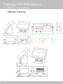
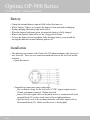
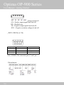
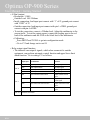
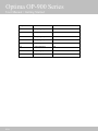
Optima OP-900 Series
User Manual
Rev. 2
Warnings
• For safety operation of the weighing indicator, please follow the following
warning/safety instructions:
• Calibration inspection and maintenance of the indicator are prohibited by nonprofessional staff
• Please ensure that the indicator has good ground
• The indicator is a static and sensitive equipment; Please cut off power during
electrical connections; Touching the internal components by hand is
prohibited; Please take anti-static prevention measures
Optima OP-900 Series
User Manual / Table of Contents
Getting Started ...........................................................................4
Overview ............................................................................................................... 4
Technical Parameters............................................................................................. 4
Indicator Drawing .................................................................................................. 5
Battery ................................................................................................................... 6
Installation ............................................................................................................. 6
Calibration and Parameter Settings ..................................................................... 10
Using Indicator.........................................................................16
Basic Weighing ................................................................................................... 16
Power On/Off ...................................................................................................... 17
Zero...................................................................................................................... 17
Tare ...................................................................................................................... 18
Changing Units .................................................................................................... 18
Hold ..................................................................................................................... 18
Print ..................................................................................................................... 18
Counting Function ............................................................................................... 19
Accumulation Function ....................................................................................... 19
RS232 Output Format.......................................................................................... 20
More Info .................................................................................23
Troubleshooting ................................................................................................... 23
Technical Support ................................................................................................ 24
3/24
Optima OP-900 Series
User Manual / Getting Started
Getting Started
Overview
Thank you for using Optima’s OP-900 series indicator for your important
application. The OP-900 series weighing indicator can be used for many type of
scales such as bench and floor scales. The basic functions are as follows:
• Hold function
• Print
• kg/lb unit conversion
• Count/Total
• Gross/Tare/Zero
• Overload reminder
Options can also be requested to include the following:
• RS232/RS485 serial interface or second display
• I/O
• 4-20mA outputs
Technical Parameters
•
•
Accuracy class: 6000 e
Resolution:
Display: 30,000
•
ADC: 2,000,000
•
Zero stability error: TK0 < 0.1μV//K
•
Span stability error: TKspn < ± 6 ppm//K
•
Sensitivity (internal): 0. 3 μV /d
•
Input voltage: -30 to +30mV DC
•
Excitation circuit: 5 VDC, 4 wire connection, 6 load cell of 350ohm
•
maximum
AC power: AC 100-250V (use only the 9V adapter supplied with the
•
indicator)
Operation temperature: -10 °C ~ +40 °C
•
Operation humidity: ≤90%RH
•
Storage temperature: -40 °C ~ +70 °C
•
4/24
Optima OP-900 Series
User Manual / Getting Started
Indicator Drawing
5/24
Optima OP-900 Series
User Manual / Getting Started
Battery
• Charge the internal battery (option) fully before first time use
• When “battery” light is on, it means the battery is low and needs recharging
• During charging, the battery light turns yellow
• When the battery light turns green, its means the battery is fully charged
• Remove the battery when not in use for a long period of time
• To keep the battery in best condition, fully discharge battery every month by
leaving the indicator on until indicator powers off
Installation
• The indicator can connect with 6 load cell of 350ohm maximum with 4 wire or 6
wire load cell. There are two connection methods between the load cell and the
indicator:
• Quick disconnect
• Terminal trip connection (inner connection)
• The excitation voltage for the load cell is 5VDC; largest output current =
120mA; maximum connect 6 350ohm load cell
• Load cell (or the signal cable for the junction box) is connected with 5 pin
terminal block (J5) on the circuit board of the weighing indicator
• Open the back cover of the weighing indicator, and insert signal cable to
the terminal block (J5); Make sure the screw is fixed tightly
6/24
Optima OP-900 Series
User Manual / Getting Started
+EXC = Positive excitation voltage to load cell
+IN = Positive output signal from load cell
HD = Shielded wire
-IN = Negative output signal from load cell
-EXC = Negative excitation voltage to load cell
•
RS232: DB9 Pin or 3 Pin
DB9 joint
Definition
Function
2
TXD
Sending data
3
RXD
Receiving data
5
GND
Ground interface
Note: if RS485, The connection pin is 2 and 5 pin.
3 Pin definition
7/24
Optima OP-900 Series
User Manual / Getting Started
• 4-20mA output
• Resolution: 1/1000
• Outside Load: 100-350ohms
• Inside connection: load input port connect with “1” of J2, ground port connect
with “GND” of J2
• Outside connection: load input port connect with pin 1 of DB9, ground port
connect with pin 6 of DB9
• To test the connection, connect a 250ohm load; Adjust the multimeter to the
current stalls; To test the output current, connect the loading port to the red
lead of the multimeter and the GND to the black lead of the multimeter
• Calibration:
• Press PRINT and TOTAL to go into configuration mode
• Go to C32 and change out to out-20
• Relay output signal function
• The indicator can output 4 signals, which when connected to outside
equipment, can perform automatic control function and upper/lower limit
alarm function. Go to setting C33 as follows:
C33=0
Output port
Port definition
Function
Out1
Close output function
No output signal
Out2
Close output function
No output signal
Out3
Close output function
No output signal
Out4
Close output function
No output signal
Out1
Open overload control function
Output overload control
signal
C33=1
Out2
Open compliance control function
Out3
Open under-load control function
Output compliance
control signal
Output under-load control
signal
Out4
Open stable control function
Output stable control
signal
C33=2,3 Preserved, no function.
8/24
Optima OP-900 Series
User Manual / Getting Started
9/24
DB9 pin
definition
port
1 pin
1st output signal pin
Out1
6 pin
1st output signal pin
Out1
2 pin
2nd output signal pin
Out2
7 pin
2nd output signal pin
Out2
3 pin
3rd output signal pin
Out3
8 pin
3rd output signal pin
Out3
4 pin
4th output signal pin
Out4
9 pin
4th output signal pin
Out4
Optima OP-900 Series
User Manual / Getting Started
Calibration and Parameter Settings
• The parameter settings menu has a calibration section (C01 to C07) and a
parameter settings section (C08 and up). To access the calibration section the
seal switch (top left of the pcb board) must be OFF as shown in the picture
below. This will allow access to all C01 and up settings. If the seal switch is
ON, then only C08 and up can be accessed by the user.
• CAUTION: If you break the official seal by opening the back of the indicator to
access the seal switch, you may need to have the indicator recertified by local
weights and measures official. Be sure to adjust the seal switch back to the
original setting after calibration/configuration has been performed.
• To enter calibration/parameter settings
• Press and hold the HOLD and PRINT key at the same time (OP-900)
• For OP-901, press ON/OFF and SET at the same time
• Navigate through the settings (C01 to C06) as shown in the following tables
by using the arrow and return keys (labeled below the indicator keys)
• Press the TOTAL key (OP-900) to save and exit settings at any time
• Press ON/OFF key (do not hold) for OP-901
• Please make sure your maximum capacity set at C04 divided by your
resolution doesn’t exceed 5,000 division. For example:
• Case #1 (Good): C02=0; C03=1; C04=5,000 (Gives 5,000 division)
• Case #2 (Bad): C02= 2; C03=1; C04=5,000 (Gives 500,000 division)
The following table shows the steps to properly calibrate the indicator in the
calibration menu:
10/24
Optima OP-900 Series
User Manual / Getting Started
Step
Method of
operation
1
Remark
[C01
After you enter calibration mode, it
display [C01 ]
]
2
Press
[C01 1]
Weight unit
option:1=kg
2=lb
3
Press
Press
Press
or
[C02 ]
[C02 0]
[C02 2]
Set decimal digits
option:0/1/2/3/4
Select decimal digit
example:two decimal point:[C02 2]
or
[C03 ]
[C03 1]
[C03 5]
Set graduation
option:1/2/5/10/20/50
Select required graduation
example:graduation 5:[C03 5]
Max capacity
or
[C04 ]
[0100.00]
[0100.00]
Press
Press
Press
Press
[C05 ]
[C05 0]
[C05 1]
[CAL 9]
。。。。。
。
[0000.00]
Press
Press
[C06 ]
[C06 0]
Zero calibration
need zero calibration
calibration zero please choose 1 and
ensure scale is empty and “stable” light
is on
Ensure Option
0=no need zero calibration
1=zero calibration, countdown. Till
show[0.00](example for two decimal
point)。
calibration
option:
0=No need calibration
1= need calibration
Load weights on scales according to
max. capacity. Suggest close to the
max capacity, at least 10% of max.
capacity.
4
5
6
7
Press
Press
Press
Press
Press
Press
Press
or
Press
Press
Press
8
11/24
Display
Press
Press
Press
/
[C06 1]
[SPAN ]
[0100.00]
or
or
[0080.00]
[CAL 9]
……
[0080.00]
[CAL End]
[C07 ]
[07 0]
[07 1]
example:max weighing 100kg:
[0100.00]
For example: the weights is 80kg; Input
0080.00, count down , then indicator
shows 0080.00 , calibration is over.
If you want to set application
function parameter. Press “PRINT” if
you want to exit press “TOTAL”
Default parameters setting
option:0=non-restore default
parameters
1=restore default parameters
Note: after the above parameters
setting finish, please do not set default
parameters to avoid the original setting
parameters is lost.
Optima OP-900 Series
User Manual / Getting Started
The following table shows the other parameter settings in the same calibration
menu as above:
Function
Setting Item parameters setting and instruction
C08
Options: 0 = close warning tone
warning tone warning tone
1 = open warning tone
Automatic
power off
Power saving
setting
C09
Automatic
power off
C10
Power saving
setting
C11
Hold function Hold mode
Kg/lb
conversion
C12
Kg/lb
conversion
Upper/lower
limit alarm
C13
Upper limit
alarm value
option:0=close auto power off
10= power off automatically if no change
within 10 minute.
30= power off automatically if no change
within 30 minute.
60= power off automatically if no
change within 60 minute.
LED Version:
option:0= close power saving setting
3= close display if no change within 3min.
5= close display if no change within 5 min.
LCD Version:
0=Close he backlight
1= backlight when the weight change or press
the keyboard
2=constant backlight
option:0=close hold function
1=Peak hold /2=Data Hold
Instruction:
Peak-hold: it shows the max. data,
mainly application for materials testing,
such as tension and pulling force.
Date-hold: it shows current weight value.
Mainly application for animal weighing.
C12=0 stop kg/lb conversion
C12=1 kg/lb conversion is ok
You can set it within the max. capacity limit
C14
Lower limit
alarm value
Inner Code
display
12/24
C15
Check inner
code
Enter C15 to check the inner code
Optima OP-900 Series
User Manual / Getting Started
Date and time
Communication
setting
Zero range
C16
Date
C17
Time
Enter C16, you can set the date, from
left to right: year/month/day
Enter C17, you can set the time from
left to right: hour/min./sec.
option:0= Close serial interface data
output
1=Continuous sending, connect big
display
C18
2=Print method, connect printer.
Serial interface data 3=Command request method
output method
,connect computer.
4=PC continues sending format,
connect computer.
5=PC/ big display continuous sending
format.
option:
C19
Baud rate
0=1200/1=2400/2=4800/3=9600
Option:
0= close manually zero setting
1=±1% max capacity
C20
2=±2% max capacity
Manually zero range 4=±4% max capacity
10=±10% max capacity
20=±20% max capacity
100=±100% max capacity
option:0= no initial zero setting
1=±1% max capacity
C21
2=±2% max capacity
Initial zero range
5=±5% max capacity
10=±10% max capacity
20=±20% max capacity
Options:
0= close zero tracking
0.5=±0.5d
1.0=±1.0d
C22
2.0=±2.0d
Automatically zero
3.0=±3.0d
tracking range
4.0=±4.0d
5.0=±5.0d
Zero tracking
C23
Automatically zero
tracking time
13/24
Note: 1. d = division
2. the zero tracking range can not
bigger than manual zero range.
Options:
0= close zero tracking time
1= 1 second
2= 2 seconds
3= 3 seconds
Optima OP-900 Series
User Manual / Getting Started
Overload range
C24
Overload range
option:00= close overload range
01d~99d
remark:d =division
Negative display
C25
Negative display
range
Option:0=-9d
10=10% max. capacity
20=20% max. capacity
50=50% max. capacity
100=100% max. capacity
Standstill time
C26
Standstill time
Option:
0= quick 1= medium 2= slow
C27
Standstill range
Option:
1= 1d 2=2d 5=5d 10=10d
D= division
Digital filter
Analog output
setting
14/24
C28
option:0= close dynamic filter
Dynamic filter
1=1 digital filter strength
Instruction:Dynamic 2=2 digital filter strength
filter is collecting the 3=3 digital filter strength
data filter before
4=4 digital filter strength
loaded weight stable. 5=5 digital filter strength
When loaded weight 6=6 digital filter strength
easily shaking (for
Note:Pls setting dynamic filter
example animal) ,
strength carefully, the No. is
you can set this filter
bigger, more stable. if the loaded
to make weight
weight shake not too much. The
display more stable
setting is less than 3
C29
option:0=close noise filter
Noise filter
1=1 digital filter strength
2=2 digital filter strength
3=3 digital filter strength
C30
Print time and date
C30=0 yy.mm.dd
C30=1 mm.dd.yy
C30=2 dd.mm.yy
C30=3 yy.mm.dd
C31 output type
C31=0 0~5Vouput
C31=1 4~20mA output
Optima OP-900 Series
User Manual / Getting Started
4~20mA current
calibrate
C32 calibrate current Refer to 2.5
Relay output
setting
C33 Relay output
Muti
communication
add.
C34 Communication C34= 0~99 Add. Code
add.
Wireless
communication
C35
Gravity of
C36
calibration location
Gravity of
C37
destination
Version No.
C38
Preserved menu C39
15/24
C33=0 close relay output
C33=1 Open relay output function 1
C3=2 Open relay output function2
C33=3 Preserved menu
C35=0~99 signal
C36=9.7000~9.9999
C37=9.7000~9.9999
Optima OP-900 Series
User Manual / Using Scale
Using Indicator
Basic Weighing
After the scale has been properly calibrated, the scale is now ready for use. Here
are the available keys as shown in the following overlays:
DISPLAY
FUNCTION
Weighing data
kg
kg
lb
lb
Hold
Gross
Data hold
Gross weight
Net
Net weight
Tare
tare
The weighing data is stable
Weight is zero
Hi
Overload
OK
ok
Lo
Underload
.
1
16/24
Decimal
PCS
Show the counting status.
TOTAL
Go to accumulation mode
Optima OP-900 Series
User Manual / Using Scale
keys
Key name
Print
Key function
1.work with “ZERO” TARE” “ON/OFF” key to
perform many functions. 2.Print
Zero the weight within tolerance
Zero
Tare
At G.W mode, get the tare weight. At N.W
mode, clear the tare, get the G.W
Gross weight
At N.W mode, check the G.W, after 3 seconds
back to N.W automatically
Counting operation
Counting
Kg/lb convert
Covert between kg and lb
Accumulation
1. Accumulation
2. work together with “ Print” to perform
The accumulation function and check the
accumulation result
Power on/off
Press 2 seconds to power on or power off
Power On/Off
• Press the ON/OFF key for about 2 seconds to power on/off the indicator. After
self inspection, the indicator will go into weighing mode.
Zero
• When the indicator is powered on, if the weight on the scale is within the initial
zero tolerance, indicator will show zero automatically. This tolerance can be set
in configuration C20 and C21.
• You can manually zero the indicator by pressing the Zero key.
1
17/24
Optima OP-900 Series
User Manual / Using Scale
Tare
• When the indicator is in gross mode (Gross status light on), pressing the Tare key
will tare the current weight. The indicator will then go into Net weight mode
(Net status light on).
• When the indicator is already in net mode (Net status light on), pressing the Tare
key will clear the tare weight and go back to gross mode (Gross status light on).
Changing Units
• Press the kg/lb key to change between the following units:
• kg (Status light kg on)
• lb (Status light lb on)
Hold
• Set configuration setting C11 to configure different hold functions
Print
• Press the Print key to print to printer connected to RS232. Please remember to
configure parameter settings C18 and C30.
1
18/24
Optima OP-900 Series
User Manual / Using Scale
Counting Function (Optional)
To perform counting function, follow the procedure below:
1. At weighing mode, load the weight to count and press the Count key. Indicator
will show “PCS 0”. Use the up and down arrow key to change the quantity that
represents the load weight. Press the return (Print) key to confirm.
2. Press Count key to return to weighing mode.
3. Repeat the above steps for counting of different goods.
Accumulation Function (Optional)
1. After the weight is at zero mode (zero light on), load weight and wait for the
stable light to turn on.
2. Press Total key and the Total light should turn on.
3. The indicator will display “n 001” and then the loaded weight.
4. Unload the weight, and load the 2nd weight until stable light on.
5. Press the Total key and the indicator will display “n 002” and then the loaded
weight.
6. Repeat steps 4 and 5 to continue to accumulate (max 999 times).
7. After accumulation is finished, press the TOTAL and PRINT key at the same
time. The display will show the number of accumulation (“n ***”) (first 4
digits) and then the total weight (last 4 digits). If you want to print the
accumulated total, press the PRINT key.
8. To exit accumulation mode, after the indicator shows all 8 digits, press and hold
Total key and the indicator will show “clr n”.
9. Press the up or down key to change from “clr n” (don’t clear total) and “clr y”
(clear total). Press the Print key to accept and exit accumulation mode.
1
19/24
Optima OP-900 Series
User Manual / Using Scale
RS232 Output Format
Big Display Continuous Output Format (C18 = 1)
Output continuous format
S
T
X
S
W
A
S
W
B
1
S
W
C
X
X
X
2
X
X
X
X
X
X
3
X
X
X
4
C
R
C
K
S
5
6
State A
Bits0,1,2
0
1
0
1
0
1
2
0
0
1
1
0
Decimal point position
XXXXXX0
XXXXXXX
XXXXX.X
0
0
1
XXXX.XX
1
0
Bits3,4
1
XXX.XXX
0
1
Division
X1
X2
1
0
State B
BitsS
function
Bits0
gross=0, net=1
Bits1
Symbol: positive =0,negative =1
Bits2
Overload(or under zero)=1
Bits3
dynamic=1
Bits4
unit:lb=0, kg=1
Bits5
Constant 1
Bits6
Constant 0
State C
Bit2
0
0
0
Bit1
0
0
1
Bit 3
Bit 5
unit
Kg or lb
g
t
printing=1
Extend
display=1
Constant 1
Bit 6
Constant 0
Bit 4
20/24
Bit0
0
1
0
Optima OP-900 Series
User Manual / Using Scale
Computer Continuous Output Format (C18 = 2)
,
,
S1
S2
CR
S3
Data
LF
S4
S1:
weight status, ST= standstill, US= not standstill, OL= overload
S2:
weight mode, GS=gross mode, NT=net mode
S3:
weight of positive and negative, “+” or ” –“
S4:
“kg” or “lb”
Data:
weight value, including decimal point
CR:
carriage return
LF:
line feed
Serial Interface Command Mode (C18 = 3)
• In this mode, indicator can receive ASCII commands listed below:
Command
NAME
Function
T
TARE
Save and clear tare
Z
ZERO
Zero gross weight
P
PRINT
Print the weight
R
G.W/N.W
Read gross weight or net weight
C
Kg/lb
Kg/lb conversion
G
G.W
Check gross weight at net weight mode
• The R command will trigger the indicator to output the following data format:
21/24
Optima OP-900 Series
User Manual / Using Scale
Print Format (C18 = 4)
ID.NO.
Date:
Time:
GROSS
TARE
NET
004 (Serial No.)
XX.XX. XX (yy.mm.dd)
XX.XX.XX (hh.mm.ss)
8.88kg (gross weight)
2.88kg (tare)
6.00kg (net weight)
PC or Big Display Continuous Sending Format (C18 = 5)
22/24
Optima OP-900 Series
User Manual / More Info
More Info
Troubleshooting
Q: What are the different error codes?
A: The following table shows the error codes and explanations:
ERROR
uuuuuu
nnnnnn
ERR1
ERR2
ERR3
23/24
REASON
SOLUTION
1. Overload
1. reduce the weight
2. wrong connection 2. check load cell connection
with load cell
3. inspection load cell. Check the
3. load cell has quality input and output
problem.
4. see Q&A below
1. calibration is no good 1.check scale is resisted or not,
2. wrong connection
foot is kept level or not.
3. load cell has quality 2.check load cell connection.
problem
3.checking load cell:check input
and output resistance to judge it
is good or not.
4. see Q&A below
Input the correct weights
During calibration, not
input the weights or the
weight is overload
The calibration weights Minimum
During calibration , the is 10% of Max. cap. Recommend
weights is below than 60%-80% of Max. Cap.
Min. required weights
1.
During calibration, the
input signal is negative 2.
3.
check the connection is
correct
check load cell is no problem
recalibration if still wrong
change the PCB
ERR4
During calibration, the After the platform is stable, start
signal is unstable
calibration
ERR5
EEPROM Error
Change PCB
ERR6
Exceed Zero Range
See Q&A below
Optima OP-900 Series
User Manual / More Info
Q: The scale does not turn on.
A: Make sure the power cord is plugged in, and that there is power. One easy way to test this is
by connecting another appliance to the same outlet and see if it’s operational.
Q: The reading goes negative when a load is applied.
A: Try interchanging the Sig+ and Sig- wiring connected to the load cell and/or junction box (if
one is used).
Q: How do I resolve ERR6 error?
A: Please follow the procedure below:
1) Turn on indicator make sure nothing is on the scale, and that the scale is level and not wobbling
2) Press and hold the “PRINT and HOLD” (for metal indicator) or “SET and ON/OFF” (for plastic
indicator) key simultaneously for a couple of seconds
3) You should see C01 now.
4) Using the arrow keys, change C01 to C20. You have to change the 1st digit from 0 to 2 first before you
can change the 2nd digit 1 to a 0.
5) Press enter (“PRINT” key for metal indicator; “SET” key for plastic indicator).
6) Change the value of C20 on the right to 100 if possible using the up arrow key. If 100 is not available
change to 20.
7) Press enter (“PRINT” key for metal indicator; “SET” key for plastic indicator).
8) You should see C21 now. Press enter (“PRINT” key for metal indicator; “SET” key for plastic
indicator).
9) Change the value on the right of C21 to 100 if available, 20 if not.
10) (“PRINT” key for metal indicator; “SET” key for plastic indicator).
11) You should see C22 now. Press the TOTAL key (metal indicator) or ON/OFF key (plastic indicator, do
not hold this button too long) to save and exit.
12) Turn off and on indicator again, and see if this resolves the ERR 6 issue. If not, then following the
Q&A answers below for resolving “nnnnnn”and “uuuuuu” errors.
Q: How do I resolve “nnnnnn” and “uuuuuu” error?
A: Please follow the procedure below:
1) Check if the cable that runs from the indicator to the junction box is damaged. If it is, replace the cable.
2) If #1 above did not resolve the issue, then open up the junction box (if available) and check to see if
there is any water damage. If so, replace the junction box.
3) If the junction box is free of visible damage (#2 above did not resolve the issue), make sure all the wires
on all 5 terminal blocks (5 wires on each terminal block) are not loose. Re-tighten the screws even if the
wires seem to be connected.
4) If #3 above did not resolve the issue, try re-calibration.
5) If #4 above did not resolve the issue, there is a possibility one or more load cells are defective (consult
with [email protected] for further instructions).
Technical Support
Please email [email protected] if you have any further questions.
24/24