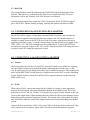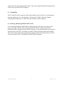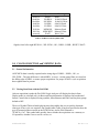
1
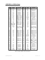
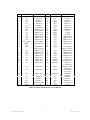
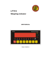
NEX-PCMCIA
PCMCIA Bus Adapter Users Manual
Including these Software Support packages:
PCMCIA
Copyright © 2008 Nexus Technology, Inc. All rights reserved.
Contents of this publication may not be reproduced in any form without the written permission
of Nexus Technology, Inc.
Brand and product names used throughout this manual are the trademarks of their respective
holders.
PCMCIA-MN-XXX
1
Doc. Rev. 1.10
Warranty Terms and License Agreement
For warranty terms, refer to the Terms and Conditions of Sale document that was included in the
product shipment. The Software License Agreement is displayed during installation. A hardcopy
of that agreement may be obtained from Nexus Technology.
All Nexus Technology products to which this manual refers are subject to the Terms and
Conditions of Sale document and the Software License Agreement, as appropriate.
Compliance with WEEE and RoHS Directives
This product is subject to European Union regulations on Waste Electrical and Electronics
Equipment. Return to Nexus Technology for recycle at end of life. Costs associated with the
return to Nexus Technology are the responsibility of the sender.
PCMCIA-MN-XXX
2
Doc. Rev. 1.10
TABLE OF CONTENTS
1.0 OVERVIEW ........................................................................................................................... 4
1.1 General Information............................................................................................................ 4
2.0 SOFTWARE INSTALLATION ............................................................................................. 4
2.1 TLA600/700........................................................................................................................ 4
2.2 DAS 9200............................................................................................................................ 5
3.0 CONFIGURING the NEX-PCMCIA BUS ADAPTER ......................................................... 5
4.0 CONNECTING to the NEX-PCMCIA ADAPTER ............................................................... 5
4.1 General................................................................................................................................ 5
4.2 92A96.................................................................................................................................. 5
4.3 TLA600/700........................................................................................................................ 6
4.4 Inserting / Removing PCMCIA DUT Cards....................................................................... 6
5.0 CLOCK SELECTION and VIEWING DATA....................................................................... 8
5.1 General Information............................................................................................................ 8
5.2 Viewing State Data with the DAS 9200 ............................................................................. 8
5.3 Viewing State Data with the TLA600/700 ......................................................................... 9
5.4 Viewing Timing Data with the DAS 9200 ......................................................................... 9
5.5 Viewing Timing Data with the TLA600/700...................................................................... 9
APPENDIX A - Necessary Signals for Clocking ......................................................................... 11
APPENDIX B - Considerations.................................................................................................... 12
B.1 PCMCIA Loading ............................................................................................................ 12
B.2 Pattern Generation............................................................................................................ 12
B.3 3.3V Support .................................................................................................................... 12
B.4 Inserting / Removing PCMCIA DUT Cards .................................................................... 12
APPENDIX C - PCMCIA Pinout ................................................................................................. 13
APPENDIX D - NEX-PCMCIA Silk Screen ............................................................................... 15
APPENDIX E - Support ............................................................................................................... 16
APPENDIX F - References .......................................................................................................... 17
TABLE OF TABLES
Table 1- PCMCIA 92A96 / TLA600/700 Wiring........................................................................... 7
Table 2- PCMCIA Control Symbol Table ...................................................................................... 8
Table 3- PCMCIA Memory Only Card Interface ......................................................................... 13
Table 4- PCMCIA I/O and Memory Card Interface..................................................................... 14
PCMCIA-MN-XXX
3
Doc. Rev. 1.10
1.0 OVERVIEW
1.1 General Information
The NEX-PCMCIA adapter has been designed to provide quick and easy connections to
interface a 68, 102, or 136 channel TLA600/700, a 92A96 or 92C96 acquisition module to a
PCMCIA card slot. (The PCMCIA designation refers to the Personal Computer Memory Card
Internal Association specification.) In addition, the method of connection permits the use of
other acquisition cards (such as the 92HS8 2GHz high-speed module), pattern generation cards
(such as the 92S32 50MHz Pattern Generator) or other measurement devices such as
oscilloscopes.
This manual assumes that the user is aware that the 92A96 and 92C96 modules from Tektronix
are essentially identical. This manual therefore refers to the 92A96 but the 92C96 could be
substituted in all cases. References to the TLA700 also apply to TLA600 and a TLA700 with a
TLA704 or TLA711 chassis with one or more 7L2/3/4 or 7M2/3/4 acquisition cards.
Appendix D is a silk-screen print of the NEX-PCMCIA Adapter board. Referring to this
drawing while reading the manual is suggested.
This manual assumes that the user is familiar with the PCMCIA Bus specification and the
Tektronix DAS 9200 or TLA600/700 Logic Analyzer. Also in the case of the TLA600/700, it is
expected that the user is familiar with Windows 95.
2.0 SOFTWARE INSTALLATION
Two 3½” diskettes have been included with the NEX-PCMCIA Bus Adapter. One is for use
with the TLA600/700 series, the other is to be used with a DAS9200 or TLA500.
2.1 TLA600/700
The PCMCIA support software is loaded in the same method as other Win95 programs. Place
the NEX-PCMCIA Install disk in the floppy drive of the TLA600/700. Select Control Panel
and run Add/Remove Programs, choose Install, Next, then Finish. Add/Remove will then run
SETUP.EXE on the floppy and install the support in its proper place on the hard disk.
To load a support into the TLA600/700, first select the desired Logic Analyzer card in the Setup
screen, select Load Support Package from the File pull-down, then choose PCMCIA and click
on Okay. Note that the Logic Analyzer card must be at least 68-channels in width.
PCMCIA-MN-XXX
4
Doc. Rev. 1.10
2.2 DAS 9200
The included diskette should be loaded onto the DAS 9200 using the Install Application
function. This function is available from the Disk Services menu of the DAS. For more
information, refer to the Tektronix DAS 9200 System User's Manual.
Load the desired support from within the 92A96 Config menu. Select "PCMCIA Support",
press <RETURN>, and the channel grouping, clocking and symbols will then be loaded.
3.0 CONFIGURING the NEX-PCMCIA BUS ADAPTER
The NEX-PCMCIA adapter is longer than a standard PCMCIA module, and is designed to
function both as signal break-out board and as an extender card. An external connector is
available to supply power to the DUT (Device Under Test) that is separate from the power
supplied by the target system. To use this feature simply wire the external power supply to the
VPP1, VPP2, VCC, and GND connections on the terminal block. To power the DUT from
external power move the jumpers at JP1, JP2, and JP3 from their default SYS setting (the lower
two pins) to the EXT setting (the upper pair of pins).
4.0 CONNECTING to the NEX-PCMCIA ADAPTER
4.1 General
When using either the 92A96 or TLA600/700, sections D2 and D3 are available for acquiring
any other signals of interest. By default the groups containing these sections (Aux_A and
Aux_B respectively) are not displayed, but they may be enabled at any time. These signals need
not be on the NEX-PCMCIA card but may be signals located on the DUT or on the controlling
system. Signals on these sections (D2 and D3) will be acquired and stored at the end of the
PCMCIA bus cycle.
4.2 92A96
When using a 92A96, connect the grouped pods (8 podlets to a group) to their appropriate
locations by following the silk-screen information printed on the adapter board. The 92A96
pods used are A0-A3, D0, D1, C0 and C2. Each pod has its proper location denoted on the silkscreen of the adapter board. When attaching the pods, follow the silk-screen information on the
board showing the ground and signal pin locations. The colored sides of the podlets, the signal
side, should face either the center of the adapter board or the board end that plugs into the host
system.
Connect the three clock leads (CLK0, CLK1, and CLK2) to their specified locations at J13 (the
only connector with 4 locations). Again, follow the silk-screened information to properly
PCMCIA-MN-XXX
5
Doc. Rev. 1.10
connect the clock input and its ground. Table 1 shows the wiring and Channel Grouping for the
92A96 when used with PCMCIA Support.
4.3 TLA600/700
The TLA600/700 will be connected in the same method as an A96. However, it's important to
note that signal group C3 is used in place of A96 group C0. Table 1 shows the Channel
Grouping and wiring for the TLA600/700 when used with PCMCIA Support.
4.4 Inserting / Removing PCMCIA DUT Cards
It is recommended that the NEX-PCMCIA adapter board be connected to the target system
prior to inserting a PCMCIA DUT. Because the NEX-PCMCIA card does not have the
mechanical guides typically found in PCMCIA designs, it is recommended that care be taken to
insert and remove the DUT as smoothly as possible. When used in this fashion and when the
DUT is powered from the target system (power jumpers in the SYS position) the power LEDs
will not be on until a DUT is installed in the NEX-PCMCIA adapter.
PCMCIA-MN-XXX
6
Doc. Rev. 1.10
Group
Name
Address
(HEX)
Control
(SYM)
Signal
Name
A25
A24
A23
A22
A21
A20
A19
A18
A17
A16
A15
A14
A13
A12
A11
A10
A9
A8
A7
A6
A5
A4
A3
A2
A1
A0
WP/IO16~
WE~/PGM~
OE~
IORD~
IOWR~
RESET
WAIT~
PCMCIA
Pin #
56
55
54
53
50
49
48
47
46
19
20
14
13
21
10
8
11
12
22
23
24
25
26
27
28
29
33
15
9
44
45
58
59
92A96
input
A3:1
A3:0
A2:7
A2:6
A2:5
A2:4
A2:3
A2:2
A2:1
A2:0
A1:7
A1:6
A1:5
A1:4
A1:3
A1:2
A1:1
A1:0
A0:7
A0:6
A0:5
A0:4
A0:3
A0:2
A0:1
A0:0
C2:0
C2:5
C2:4
C2:6
C2:7
C2:2
C2:3
TLA700
input
A3:1
A3:0
A2:7
A2:6
A2:5
A2:4
A2:3
A2:2
A2:1
A2:0
A1:7
A1:6
A1:5
A1:4
A1:3
A1:2
A1:1
A1:0
A0:7
A0:6
A0:5
A0:4
A0:3
A0:2
A0:1
A0:0
C2:0
C2:5
C2:4
C2:6
C2:7
C2:2
C2:3
Group
Name
Data
(HEX)
Misc
(OFF)
Clock:0
Clock:1
Clock:2
Clock:3
Signal
Name
D15
D14
D13
D12
D11
D10
D9
D8
D7
D6
D5
D4
D3
D2
D1
D0
D_CLK
RFU57
SPKR
STSCHG
RFSH
REG~
CD2~
CD1~
CE2~
CE1~
INPACK~
PCMCIA
Pin #
41
40
39
38
37
66
65
64
6
5
4
3
2
33
31
30
*
57
62
63
43
61
67
36
42
7
60
D_CLK
IORD~
RFSH
*
44
43
92A96
input
D1:7
D1:6
D1:5
D1:4
D1:3
D1:2
D1:1
D1:0
D0:7
D0:6
D0:5
D0:4
D0:3
D0:2
D0:1
D0:0
C0:4
C0:3
C0:1
C0:0
C0:2
A3:3
A3:7
A3:6
A3:5
A3:4
A3:2
TLA700
input
D1:7
D1:6
D1:5
D1:4
D1:3
D1:2
D1:1
D1:0
D0:7
D0:6
D0:5
D0:4
D0:3
D0:2
D0:1
D0:0
--C3:3
C3:1
C3:0
C3:2
A3:3
A3:7
A3:6
A3:5
A3:4
A3:2
Table 1- PCMCIA 92A96 / TLA600/700 Wiring
* Derived signal
~ Denotes a low true signal
PCMCIA-MN-XXX
7
Doc. Rev. 1.10
Pattern
xxxxx1x
0xx010x
0xx100x
1xx010x
1xx100x
110110x
101110x
xxxxxx0
Symbol
RESET
I/O RD16
I/O WR16
I/O RD8
I/O WR8
MEM RD
MEM WRT
WAIT
Meaning
Reset
16-bit I/O Read
16-bit I/O Write
8-bit I/O Read
8-bit I/O Write
Memory Read
Memory Write
Wait Cycle
Table 2- PCMCIA Control Symbol Table
Signals, from left to right:WP/IO16~, WE~/PGM~, OE~, IORD~, IOWR~, RESET, WAIT~
5.0 CLOCK SELECTION and VIEWING DATA
5.1 General Information
All PCMCIA data is usually acquired on the rising edge of IORD~, IOWR~, OE~, or
WE~/PGM~. The only difference is when IORD~ is active - certain control lines are stored on
the falling edge of IORD~ to ensure proper acquisition. For proper PCMCIA cycle acquisition
these signals must be present.
5.2 Viewing State Data with the DAS 9200
After an acquisition is made the DAS 9200 Logic Analyzer will display the data in State
Display mode (as a default only). Address and Data information is displayed in hexadecimal
format; Control data is displayed using symbols; Miscellaneous and both Auxiliary data groups
default to OFF.
The use of Symbol Tables when displaying state data enables the user to quickly determine
what type of bus cycle was acquired. One symbol table (Table 4) has been provided to show the
type of transaction that occurred on the PCMCIA bus, and its DAS filename is
"PCMCIA_Ctrl". This symbol table quickly shows whether the acquisition was a memory or
I/O operation, whether it was a read or a write, etc.
PCMCIA-MN-XXX
8
Doc. Rev. 1.10
It is important to note that changing the group, channel, or wiring of the Control group can
result in incorrect symbol information being displayed.
5.3 Viewing State Data with the TLA600/700
After making an initial acquisition, the TLA600/700 will display the data in the Listing (State)
format. Address and Data information is displayed in hexadecimal format; Transfer, Mode, and
Misc data is displayed using symbols; Interrupts (Intrpts) and Bus Master (BusMstr) data
groups default to Hexadecimal.
The use of Symbol Tables when displaying state data enables the user to quickly determine
what type of bus cycle was acquired. When using NEX-PCMCIA, a symbol table
(PCMCIA_CTRL) has been provided to show the type of transfer that occurred on the
PCMCIA bus. PCMCIA_CTRL has the same definition as the symbol table used in the DAS
(see Table 4).
Again, it must be noted that changing the group, channel, or wiring of the Control group can
result in incorrect symbol information being displayed.
5.4 Viewing Timing Data with the DAS 9200
It may be useful to display acquired information using the Timing Diagram display of the DAS
9200. (Note that, unlike some other logic analyzers, with the DAS 9200 there is no need to reacquire PCMCIA data when changing from one display mode to another. The same data can be
viewed in either format.) This method of data display can be particularly useful when an
asynchronous acquisition has been made (using the DAS 9200 internal acquisition clock) to
determine the relationships between signal edges.
The 92A96 is particularly well suited for this mode of operation because of its ability to acquire
data asynchronously at a 400MHz rate, providing 2.5ns of timing resolution.
Refer to the appropriate Tektronix DAS 92A96 Module User's Manual for more detailed
information on formatting the display of the acquired data.
5.5 Viewing Timing Data with the TLA600/700
By default, the TLA600/700 will display an acquisition in the Listing (State) mode. However,
the same data can be displayed in Timing form by adding a Waveform Display window. This is
done by clicking on the Window pull-down, selecting New Data Window, clicking on
Waveform Window Type, then choosing the Data Source. Two choices are presented:
PCMCIA and PCMCIA-MagniVu. The first (PCMCIA) will show the exact same data (same
acquisition mode) as that shown in the Listing window, except in Timing format. The second
selection, PCMCIA-MagniVu, will show all of the channels in 2GHz MagniVu mode, so that
edge relationships can be examined at the module’s trigger point. With either selection, all
PCMCIA-MN-XXX
9
Doc. Rev. 1.10
channels can be viewed by scrolling down the window. Refer to the TLA600/700 System
User’s Manual for additional information on formatting the Waveform display.
Like all Tektronix logic analyzers, the acquired data can be viewed in Timing format as well as
State format, without having to make another acquisition. Simply select "Timing" in the display
section of the Prism.
PCMCIA-MN-XXX
10
Doc. Rev. 1.10
APPENDIX A - Necessary Signals for Clocking
To properly acquire PCMCIA bus activity, the following signals must be provided: IORD~,
IOWR~, OE~, and WE~/PGM~. With the exception of IORD~ the rising edge of these signals
is used as the active clocking edge. When IORD~ is active both edges are used to acquire data.
PCMCIA-MN-XXX
11
Doc. Rev. 1.10
APPENDIX B - Considerations
B.1 PCMCIA Loading
It must be noted that the NEX-PCMCIA Bus Adapter does not provide any buffering of the
PCMCIA bus signals. This was a conscious design decision that was made by balancing the
tradeoffs of loading versus design simplicity and signal acquisition accuracy. By not
introducing signal buffers it is possible, using the NEX-PCMCIA adapter, to see the exact
timing relationships and signal waveforms from the system. It is also much easier to connect
pattern generators to the bus since buffer direction is not a concern. It is believed that the signal
loading of the 92A96 or TLA600/700 acquisition cards is low enough so that PCMCIA signal
degradation will not occur.
B.2 Pattern Generation
Because there is no buffer circuitry on the NEX-PCMCIA Adapter, it is well suited for use with
the 92S16 and 92S32 Pattern Generator modules available for the DAS 9200. By connecting
pattern generator probes to the A96 signal connectors on the Adapter, desired bus activity can
be simulated. This can be particularly effective when trying to debug interrupt or DMA
conflicts.
It should be noted that, because of the pin spacing of the A96 connectors, it is not recommended
that the Tektronix P6464 or P6465 pattern generator probes be used without providing adequate
cooling for their podlets. These probes use active podlets that can get very warm in use. A
better choice would be the P6463 pods which are passive and do not have such cooling
requirements.
B.3 3.3V Support
For support of 3.3V PCMCIA cards please contact Nexus Technology, Inc. for upgrade
information.
B.4 Inserting / Removing PCMCIA DUT Cards
It is recommended that the NEX-PCMCIA adapter board be connected to the target system
prior to inserting a PCMCIA DUT. Because the NEX-PCMCIA card does not have the
mechanical guides typically found in PCMCIA designs, it is recommended that care be taken to
insert and remove the DUT as smoothly as possible. When used in this fashion and when the
DUT is powered from the target system (power jumpers in the SYS position) the power LEDs
will not be on until a DUT is installed in the NEX-PCMCIA adapter.
PCMCIA-MN-XXX
12
Doc. Rev. 1.10
APPENDIX C - PCMCIA Pinout
Pin
1
2
3
4
5
6
7
8
9
10
11
12
13
14
15
16
17
18
Signal
GND
D3
D4
D5
D6
D7
CE1~
A10
OE~
A11
A9
A8
A13
A14
WE~/PGM~
RDY/BSY
Vcc
Vpp1
Function
Ground
Data bit 3
Data bit 4
Data bit 5
Data bit 6
Data bit 7
Card enable 1
Address bit 10
Output enable
Address bit 11
Address bit 9
Address bit 8
Address bit 13
Address bit 14
Write enable
Ready/Busy
Pin
35
36
37
38
39
40
41
42
43
44
45
46
47
48
49
50
51
52
Signal
GND
CD1~
D11
D12
D13
D14
D15
CE2~
RFSH
RFU
RFU
A17
A18
A19
A20
A21
Vcc
Vpp2
19
20
21
22
23
24
25
A16
A15
A12
A7
A6
A5
A4
Programming
Supply Voltage
1
Address bit 16
Address bit 15
Address bit 12
Address bit 7
Address bit 6
Address bit 5
Address bit 4
53
54
55
56
57
58
59
A22
A23
A24
A25
RFU
RESET
WAIT~
26
27
28
A3
A2
A1
Address bit 3
Address bit 2
Address bit 1
60
61
62
RFU
REG~
BVD2
29
A0
Address bit 0
63
BVD1
30
31
32
33
34
D0
D1
D2
WP
GND
Data bit 0
Data bit 1
Data bit 2
Write protect
Ground
64
65
66
67
68
D8
D9
D10
CD2~
GND
Function
Ground
Card detect 1
Data bit 11
Data bit 12
Data bit 13
Data bit 14
Data bit 15
Card enable 2
Refresh
Reserved
Reserved
Address bit 17
Address bit 18
Address bit 19
Address bit 20
Address bit 21
Programming
Supply Voltage
2
Address bit 22
Address bit 23
Address bit 24
Address bit 25
Reserved
Card Reset
Extend bus
cycle
Reserved
Register select
Battery voltage
detect 2
Battery voltage
detect 1
Data bit 8
Data bit 9
Data bit 10
Card detect 2
Ground
Table 3- PCMCIA Memory Only Card Interface
PCMCIA-MN-XXX
13
Doc. Rev. 1.10
Pin
1
2
3
4
5
6
7
8
9
10
11
12
13
14
15
16
17
18
Signal
GND
D3
D4
D5
D6
D7
CE1~
A10
OE~
A11
A9
A8
A13
A14
WE~/PGM~
IREQ~
Vcc
Vpp1
Function
Ground
Data bit 3
Data bit 4
Data bit 5
Data bit 6
Data bit 7
Card enable 1
Address bit 10
Output enable
Address bit 11
Address bit 9
Address bit 8
Address bit 13
Address bit 14
Write enable
Interrupt Request
Pin
35
36
37
38
39
40
41
42
43
44
45
46
47
48
49
50
51
52
Signal
GND
CD1~
D11
D12
D13
D14
D15
CE2~
RFSH
IORD~
IOWR~
A17
A18
A19
A20
A21
Vcc
Vpp2
19
20
21
22
23
24
25
26
A16
A15
A12
A7
A6
A5
A4
A3
Programming
Supply Voltage 1
Address bit 16
Address bit 15
Address bit 12
Address bit 7
Address bit 6
Address bit 5
Address bit 4
Address bit 3
53
54
55
56
57
58
59
60
A22
A23
A24
A25
RFU
RESET
WAIT~
INPACK~
27
A2
Address bit 2
61
REG~
28
A1
Address bit 1
62
SPKR~
29
A0
Address bit 0
63
STSCHG~
30
31
32
33
34
D0
D1
D2
IOIS16~
GND
Data bit 0
Data bit 1
Data bit 2
IO Port is 16-bit
Ground
64
65
66
67
68
D8
D9
D10
CD2~
GND
Function
Ground
Card detect 1
Data bit 11
Data bit 12
Data bit 13
Data bit 14
Data bit 15
Card enable 2
Refresh
IO Read
IO Write
Address bit 17
Address bit 18
Address bit 19
Address bit 20
Address bit 21
Programming
Supply Voltage 2
Address bit 22
Address bit 23
Address bit 24
Address bit 25
Reserved
Card Reset
Extend bus cycle
Input Port
Acknowledge
Register select &
IO Enable
Audio Digital
Waveform
Card Status
Changed
Data bit 8
Data bit 9
Data bit 10
Card detect 2
Ground
Table 4- PCMCIA I/O and Memory Card Interface
PCMCIA-MN-XXX
14
Doc. Rev. 1.10
APPENDIX D - NEX-PCMCIA Silk Screen
PCMCIA-MN-XXX
15
Doc. Rev. 1.10
APPENDIX E - Support
About Nexus Technology, Inc.
Established in 1991, Nexus Technology, Inc. is dedicated to developing, marketing, and
supporting Bus Analysis applications for Tektronix Logic Analyzers.
We can be reached at:
Nexus Technology, Inc.
78 Northeastern Blvd. #2
Nashua, NH 03062
TEL: 877-595-8116
FAX: 877-595-8118
Web site: http://www.nexustechnology.com
Support Contact Information
Technical Support
General Information
Quote Requests
[email protected]
[email protected]
[email protected]
We will try to respond within one business day.
If Problems Are Found
Document the problem and e-mail the information to us. If at all possible please forward
a Saved System Setup (with acquired data) that shows the problem. Do not send a text
listing alone as that does not contain enough data for analysis. To prevent corruption
during the mailing process it is strongly suggested that the Setup be zipped before
transmission.
PCMCIA-MN-XXX
16
Doc. Rev. 1.10
APPENDIX F - References
Tektronix DAS 9200 System User's Manual
Tektronix DAS 9200 92A96 User's Manual
Tektronix TLA600/700 System User's Manual
Tektronix TLA600/700 Logic Analyzer User's Manual
PCMCIA PC Card Standard, Release 2.1, July 1993
“PCMCIA Developer’s Guide, The” by Michael T. Mori
Published by Sycard Technology
PCMCIA-MN-XXX
17
Doc. Rev. 1.10