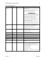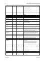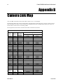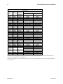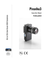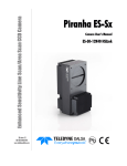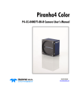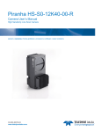
1
Piranha3 P3-S0-16K40-00-R P3-S0-16K20-00-R P3-80-16K40-00-R Camera User’s Manual 27-Feb-12 03-032-20099-00 www.teledynedalsa.com Piranha3 16K HSLink and Camera Link User Manual 2 © 2012 Teled yne DALSA. All inform ation provid ed in this m anual is believed to be accurate and reliable. No responsibility is assum ed by Teled yne DALSA for its use. Teled yne DALSA reserves the right to make changes to this inform ation w ithout notice. Reprod uction of this m anual in whole or in part, by any m eans, is prohibited w ithout prior perm ission having been obtained from Teled yne DALSA. About Teledyne Technologies and Teledyne D ALSA, Inc. Teled yne Technologies is a lead ing provid er of sophisticated electronic subsystem s, instrum entation and com m unication prod ucts, engineered system s, aerospace engines, and energy and pow er generation system s. Teled yne Technologies’ operations are prim arily located in the United States, the United Kingd om and Mexico. For more inform ation, visit Teled yne Technologies’ w ebsite at w ww .teled yne.com . Teled yne DALSA, a Teled yne Technologies com pany, is an international lead er in high performance digital im aging and sem icond uctors w ith approxim ately 1,000 em ployees world w id e, headquar tered in Waterloo, Ontario, Canada. Established in 1980, the com pany d esigns, d evelops, m anufactures and m arkets d igital im aging prod ucts and solutions, in ad d ition to provid ing MEMS prod ucts and services. For more inform ation, visit Teled yne DALSA’s w ebsite at w w w.teled ynedalsa.com. Support For further inform ation not included in this manual, or for inform ation on Teled yne DALSA’s extensive line of im age sensing prod ucts, please contact: N orth America Europe Asia Pacific 605 McMurray Rd Waterloo, ON N2V 2E9 Canada Breslauer Str. 34 Ikebukuro East 13F D-82194 Gröbenzell (Munich) 3-4-3 H igashi-Ikebukuro Germ any Toshim a-ku, Tokyo 170-0013 Tel: 519 886 6000 Fax: 519 886 8023 Tel: +49 - 8142 – 46770 Japan w w w.teled ynedalsa.com Fax: +49 - 8142 – 467746 Tel: 81 3 5960 6353 sales.am ericas@teled yned alsa.com support@teled yned alsa.com w w w.teled ynedalsa.com Fax: 81 3 5960 6354 (fax) sales.europe@teled ynedalsa.com support@teled yned alsa.com w w w.teled ynedalsa.com 03-032-20099-00 sales.asia@teled yned alsa.com support@teled yned alsa.com Teledyne DALSA Piranha3 16K HSLink and Camera Link User Manual 3 Contents Piranha3 16k CMOS Line Scan Camera _________________________________________________________ 5 1.1 Camera Highlights ....................................................................................................................................................... 5 1.2 Camera Performance Specifications ............................................................................................................................ 6 1.3 Responsivity ................................................................................................................................................................. 8 Camera Hardware Interface ________________________________________________________________ 9 2.1 Installation Overview ................................................................................................................................................... 9 2.2 Input/Output Connectors and LED ............................................................................................................................... 10 HSLink Pinout ................................................................................................................................................. 12 Input Signals ................................................................................................................................................... 12 Output Signals ................................................................................................................................................ 13 Frame Grabbers .............................................................................................................................................. 13 HSLINK and Frame Grabber Supplementary Information ............................................................................. 14 Camera Link Configuration ............................................................................................................................ 16 Input Signals, Camera Link ............................................................................................................................ 19 Output Signals, Camera Link .......................................................................................................................... 19 2.3 Camera Link Video Timing .......................................................................................................................................... 19 Software Interface: How to Control the Camera __________________________________________________ 21 Setting Baud Rate ........................................................................................................................................... 22 Camera Help Screen ....................................................................................................................................... 22 3.1 First Power Up Camera Settings .................................................................................................................................. 22 3.2 Exposure Mode and Line Rate ..................................................................................................................................... 23 How to Set Exposure Mode and Line Rate ...................................................................................................... 23 Setting the Exposure Mode ............................................................................................................................. 23 3.3 Data Processing ........................................................................................................................................................... 25 Processing Chain Overview and Description ................................................................................................... 25 Calibrating the Camera to Remove Non-Uniformity (Flat Field Correction) .................................................. 26 Digital Signal Processing for Processing......................................................................................................... 29 3.4 Saving and Restoring Settings ..................................................................................................................................... 31 3.5 Diagnostics ................................................................................................................................................................... 33 Returning a Single Line of Video .................................................................................................................... 34 Returning Averaged Lines of Video ................................................................................................................ 34 Returning All Camera Settings with the Camera Parameter Screen .............................................................. 36 Returning Camera Settings with Get Commands............................................................................................ 36 Optical and Mechanical ___________________________________________________________________ 37 4.1 Lens Mounts ................................................................................................................................................................. 39 4.2 High Temperature and Mounting ................................................................................................................................ 39 Troubleshooting ________________________________________________________________________ 40 Teledyne DALSA 03-032-20099-00 4 Piranha3 16K HSLink and Camera Link User Manual 5.1 Common Solutions ....................................................................................................................................................... 40 LED ................................................................................................................................................................. 40 Connections ..................................................................................................................................................... 40 Power Supply Voltages ................................................................................................................................... 40 EXSYNC ........................................................................................................................................................... 40 Data Clocking/Output Signals......................................................................................................................... 40 5.2 Troubleshooting Using the Serial Interface ................................................................................................................. 41 Communications.............................................................................................................................................. 41 Verify Parameters ........................................................................................................................................... 41 Verify Factory Calibrated Settings ................................................................................................................... 41 Verify Timing and Digital Video Path ............................................................................................................. 41 Generating Test Patterns ................................................................................................................................ 41 Verify Voltage ................................................................................................................................................. 41 Verify Temperature ......................................................................................................................................... 41 Verify Pixel Coefficients ................................................................................................................................... 42 5.3 Specific Solutions ......................................................................................................................................................... 42 No Output or Erratic Behavior ........................................................................................................................ 42 Line Dropout, Bright Lines, or Incorrect Frame Rate ..................................................................................... 42 Noisy Output ................................................................................................................................................... 42 Dark Patches ................................................................................................................................................... 42 Error Handling and Command List ____________________________________________________________ 43 A1 Error Handling ............................................................................................................................................................. 43 A2 Commands: Quick Reference ....................................................................................................................................... 44 Camera Link Map _______________________________________________________________________ 48 EMC Declaration ________________________________________________________________________ 51 Revision History ________________________________________________________________________ 52 Index________________________________________________________________________________ 53 03-032-20099-00 Teledyne DALSA Piranha3 16K HSLink and Camera Link User Manual 5 1 Piranha3 16k CMOS Line Scan Camera 1.1 Camera Highlights Features 16, 384 pixels, 3.5 µm x 3.5 µm pixel pitch, 100% fill factor. 1,179 MPix / s (H SLink) and 655 MPix/ s (Cam era Link) d ata rates. 72 kH z (P3-S0-16k40 H SLink) and 40 kH z (P3-S0-16k20 H SLink and P3-80-16K40 Cam era Link) line rates. Programmability H SLink and Cam eraLink control interface, 115200 fixed signal bau d rate. (Fu tu re m od els u pgrad ed to GenICam ). Program m able gain, line rate, trigger m od e, test pattern ou tpu t, and cam era d iagnostics. Flat-field correction—m inim izes lens vignetting, non-u niform lighting, and sensor FPN and PRN U. Description The Piranha3 16k CMOS line scan cam era raises resolu tion and speed to a new level. The 16k pixel resolu tion and u p to a speed y 72 kH z line rate is id eally su ited for the inspection of large -area flat-p anel d isplays and printed circu it board s. Applications Flat-p anel d isplay inspection Printed circu it board inspection Parcel sorting H igh perform ance d ocu m ent scanning H igh throu ghpu t ap plications Teledyne DALSA 03-032-20099-00 Piranha3 16K HSLink and Camera Link User Manual 6 Models Table 1: Piranha P3-S0, P3-80 Camera Models Overview Model Number Description P3-S0-16K40-00-R P3-S0-16K20-00-R P3-80-16K40-00-R 16k resolution, 72 kH z line rate, 1179 Mpix/ s throughput, H SLink interface. 16k resolution, 40 kH z line rate, 655 Mpix/ s throughput, H SLink interface. 16k resolution, 40 kH z line rate, 655 Mpix/ s throughput, Cam era Link interface. 1.2 Camera Performance Specifications Table 2: Camera Performance Specifications Feature / Specification Im ager Form at Resolution Pixel Fill Factor Pixel Size Antibloom ing CMOS line scan 16, 384 pixels 100 % 3.5 µm x 3.5 µm 100 x Optical Interface Back Focal Distance Sensor Alignm ent (aligned to sid es of cam era) Flatness y (parallelism ) x y z z Lens Mount 12 m m 25 µm 0.08° or 81 µm ± 50 µm ± 50 µm ± 250 µm ± 0.1° M72 x 0.75 Mechanical Interface Cam era Size Mass Connectors Pow er Control / Data Mounting H oles 80 m m (W) x 150 m m (L) x 77 m m (D) / 54 m m w ithout optional heatsink < 800 g H irose 12 V to 15 V DC H SLink, Cam eraLink M4x0.7, 7.0 d epth Electrical Interface Input Voltage Pow er Dissipation 1 Operating Tem perature Bit Depth Output Data Configuration 03-032-20099-00 12 V to 15 V DC (at cam era) 20 W 0 ºC to 50 °C 8 bit, 10 bit, 12 bit (H SLink m od els) 8 bit and 10 bit (Cam era Link m od el) H SLink, Cam eraLink Teledyne DALSA Piranha3 16K HSLink and Camera Link User Manual Operating Ranges P3-S0-16k40 P3-S0-16k20 and P3-80-16k40 1 Hz 72 KH z 1 Hz 40 KH z 1,179 Mpix/ s 0 d B to +20 d B 655 Mpix/ s 0 d B to +20 d B Minim um Line Rate Maxim um Line Rate Throughput Gain 7 Test conditions unless otherwise noted: Line Rate: 10 kH z. N om inal Gain setting 0 d B. Light Sou rce: Broad band Qu artz H alogen, 3250 k, w it h 700 nm IR cu toff filter installed . All specifications are m easu red at 25 °C (front plate m easu rem ent). 1. Measu red at the front plate. It is the u ser’s responsibility to insu re that the operating tem peratu re d oes not exceed this range. Performance* Gain 0 dB Min Typ Max Gain +10 dB Min Typ Max Gain +20 dB Min Typ Max Dynam ic Range Rand om N oise DN rm s 2 SEE nJ/ cm 500 160 50 0.5 2 N EE pJ/ cm Corrected Broad band Responsivity 2 (DN / nJ/ cm ) FPN DN p -p w ith correction FPN DN p -p w / o correction PRN U DN p -p w ith correction PRN U % w / o correction Saturation Outpu t Am plitud e DN 1.5 4.8 0.8 0.26 0.08 1.6 2.8 1.6 8.8 1.6 28 2 4 2 25 13 41 25 25 255 *Measu sed in 8-bit configu ration. Teledyne DALSA 03-032-20099-00 8 Piranha3 16K HSLink and Camera Link User Manual 1.3 Responsivity Responsivity vs. Wavelength: Measu red from the cam era . 03-032-20099-00 Teledyne DALSA Piranha3 16K HSLink and Camera Link User Manual 9 2 Camera Hardware Interface 2.1 Installation Overview (This installation overview assu m es you have not installed any system com ponents yet.) When installing you r cam era, you shou ld take these step s: 1. Pow er d ow n all equ ipm ent. 2. Follow the m anu factu rer’s instru ctions to install the fram egrabber (if ap plicable). Be su re to observe all static p recau tions. 3. Install any necessary im aging softw are. 4. Before connecting pow er to the cam era, test all pow er su p plies. Ensu re that all the correct voltages are present at the cam era end of the pow er cable. Pow er su pp lies m u st m eet the requ irem en ts d efined in the Pow er Connector section below . 5. Inspect all cables and connectors p rior to installation. Do not u se d am aged cables or connectors or the cam era m ay be d am aged . 6. Connect d ata and pow er cables. 7. After connecting cables, ap ply pow er to the cam era. 8. Use the verify voltage (vv) com m and to verify that the cam era is receiving a voltage of 12 to 15 DC. If the cam era is receiving less than the recom m end ed voltage, then you m ay have to u pgrad e and / or shorten the pow er cable you are u sing. 8. Check the d iagnostic LED. See LED Statu s Ind icator for an LED d escription. You m u st also set u p the other com ponents of you r system , inclu d ing light sou rces, cam era m ou nts *, host com pu ters, optics, encod ers, and so on. *Please see 4.2 H igh Tem peratu re and Mou nting for m ore inform ation on cam era m ou nting and heat d ispertion. Teledyne DALSA 03-032-20099-00 Piranha3 16K HSLink and Camera Link User Manual 10 2.2 Input/Output Connectors and LED The cam era u ses: A d iagnostic LED for m onitoring the cam era. See LED Statu s Ind icator in section LED Statu s Ind icator for d etails. A 6-pin H irose connector for pow er. Refer to the Pow er Connector section below for d etails. The H SLink m od les u se a SFF_8470 / CX4 (w ith thu m bscrew s) for control, d ata and serial com m u nication. The Cam era Link m od el u ses 2 high -d ensity 26-pin MDR26 connectors for control, d ata and serial com m u nication. Figure 1: Input and Output Connectors Power A + 12 V to + 15 V DC Hirose 6-pin HR10A-7P-6S Control & Data HSLink SFF_8470 or Cx4 with thumbscrews C Camera Link (Full Configuration) High-density 26-pin MDR26 connector Status C D B D Diagnostic LED D A P3-80-16K40-00-R Camera Link C B A ! P3-S0-16Kx0-00-R HSLink WARNING: It is extremely important that you supply the appropriate voltages to your camera. Incorrect voltages will damage the camera. LED Status Indicator The cam era is equ ipped w ith an LED u sed to d isplay the operational statu s of the cam era. The table below su m m arizes the operating states of the cam era and the correspond ing LED states. When m ore than one cond ition is active, the LED ind icates the cond ition w ith the highest priority. Er ror and w arning states are accom p anied by correspond ing m essages fu rther d escribing the cu rrent cam era statu s. Table 3: HSLink Diagnostic LED Color of Status LED Green solid Green blinking, fast Green blinking, slow Orange (red and green on together) solid 03-032-20099-00 Meaning Cam era is operational and functioning correctly. FG only - LVAL present but not grabbing (20 second tim e out) Waiting for LVAL/ Trigger Line Scan – 5 second tim eout Running on FPGA/ m icro backup Teledyne DALSA Piranha3 16K HSLink and Camera Link User Manual 11 Color of Status LED Meaning Orange blinking, slow Orange one pulse of 0.2 sec Red blinking, fast Red blinking, m edium Red blinking, slow Red / Green alternating, fast Red / Green alternating, m edium Red / Green alternating, slow Loss of functionality Rand om Error w ith H SLIN K Fatal Error- Loss of FPGA code and or m icro cod e Fatal Error- Loss of other hardw are w hich prevents operation Over tem perature (H SLIN K CMD channel still functional) Link Up , but id le not locked (held in Farend reset) Incom patilbe H SLIN K configu ration Looking for Link Power Connectors 2.2.2 Power Connector Figure 2: Hirose 6-pin Circular Male—Power Connector Hirose 6-pin Circular Male Table 4: Hirose Pin Description 6 1 Pin Description 5 2 1 Min +12 to Max +15V 4 3 Mating Part: HIROSE HR10A-7P-6S 2 3 Min +12 to Max +15V Min +12 to Max +15V Pin 4 5 6 Description GN D GN D GN D The cam era requ ires a single voltage inpu t (+12 V to +15 V DC). The cam era m eets all perform ance specifications u sing stand ard sw itching pow er su p plies, althou gh w ell-regu lated linear su p plies p rovid e optim u m perform ance. ! WARNING: When setting up the camera’s power supplies follow these guidelines: Ap ply the ap propriate, reliable voltages Protect the cam era w ith a slow-blow fuse between pow er su pply and cam era (2x nom inal cu rrent). Do not u se the shield on a m u lti-cond u ctor cable for grou nd . Keep lead s as short as p ossible to red u ce voltage d rop. Use high -qu ality linear su p plies to m inim ize noise. Use an isolated type p ow er su pply to prevent LVDS com m on m od e range violation. A stable su pply of pow er m u st be m aintained d u ring cod e u pgrad es. Cam era w ill fail if pow er is lost or u nstable w hile u pd ating cod e. The u ser can not recover from this failu re and the cam era w ill have to be retu rned to Teled yne DALSA for repair. Note: Camera performance specifications are not guaranteed if your power supply does not meet these requirements. Teledyne DALSA 03-032-20099-00 Piranha3 16K HSLink and Camera Link User Manual 12 Data Connectors HSLink Pinout SFF_8470 (or CX4) with thumbscrews Signal Camera Frame Grabber Input Frame Grabber Signal DataTx 2+ S16 S1 DataRx 2+ DataTx 2- S15 S2 DataRx 2- DataTx 1+ S14 S3 DataRx 1+ DataTx 1- S13 S4 DataRx 1- DataTx 0+ S12 S5 DataRx 0+ DataTx 0- S11 S6 DataRx 0- Cm d _T+ S10 S7 Cm d R+ Cm d _T- S9 S8 Cm d R- Cm d _R- S8 S9 Cm d _T- Cm d _R+ S7 S10 Cm d _T+ DataTx 5- S6 S11 DataRx 5- DataTx 5+ S5 S12 DataRx 5+ DataTx 4- S4 S13 DataRx 4- DataTx 4+ S3 S14 DataRx 4+ DataTx 3- S2 S15 DataRx 3- DataTx 3+ S1 S16 DataRx 3+ Signal Ground G1- G9 G1- G9 Signal Ground Signal Ground H 1-H 2 H 1-H 2 Signal Ground Input Signals The cam era accepts control inpu ts throu gh the H SLink connector. Table 5: Camera Control Configuration Signal Configuration CC1 EXSYN C The camera ships in internal sync, internal programmed integration. EXSYNC (Triggers Frame Readout) Fram e rate can be set internally u sing the serial interface. The external control signal EXSYN C is optional and enabled throu gh the serial interface. This cam era u ses the falling edge of EXSYN C to trigger pixel read ou t. See section Exp osu re Mod e and Line Rate for d etails on how to set fram e tim es, exposu re tim es, and cam era m od es. An Important N ote: Do not stop im aging w ith the ESYN C signal high . If the EXSYN C signal is high w hen im aging stops an im aging artifact w ill rem ain on the next line. 03-032-20099-00 Teledyne DALSA Piranha3 16K HSLink and Camera Link User Manual 13 Output Signals N ote that LVAL and FVAL are em bed d ed in d ata lanes. For ad d itional inform ation refer to the H SLink su pp lem entary inform ation below . Camera Rx Tx 5 serial lanes (8 or 10 bit) 6 serial lanes (12 bit) @ 312.5 Mb/sec Frame Grabber Frame Grabbers The cam eras (H SLink) are com patible w ith the Xcelera-H S PX8 fram egrabber. Teledyne DALSA 03-032-20099-00 Piranha3 16K HSLink and Camera Link User Manual 14 HSLINK and Frame Grabber Supplementary Information Teled yne DALSA d esigned and pioneered the H SLink as a com p rehensive cam era-fram e grabber com m u nication stand ard targeted at m achine vision ind u stry u se. The H SLink 12k and fram e grabber prod u ct are based on the fu nd am ental cap abilities of this new interface. We are w orking w ith ind u stry partners to im prove and to broad en the interface’s ap peal for the m achine vision ind u stry and as a resu lt expect that the original specification w ill change and be im proved . Prod u cts d elivered d u ring this d raft specification p hase w ill be field u pgrad eable so that cu stom ers can gain the benefit from an ind u stry ap proved interface. The table below su m m arizes the m ajor fu nctions su p ported . HSLINK Function Production Cable Disconnect Recovery Yes Data Forw ard ing Yes Com m unication Betw een FG No Vid eo Data Resend No LED functions GeniCam Trigger Control Yes No Yes 12 bit m od e Yes Missed Trigger Flag DATA CRC Error Flag H ead er Error Flag 8b/ 10B Error counter Test Patterns Data Lost Flag Cam era Data buffer overflow Id le Lock Lost Far end Reset Cm d Packet Failure Master/ Slave H SLIN K reset Yes Yes 03-032-20099-00 Yes Yes Yes No No Comment Cam eras w ill only properly lock to fram e grabber w hen the cam era is turned on before or after starting the d ata acquisition program . Tu rn off the cam era w hen exiting a program that uses the Fram e grabber. Custom er m ust id entify the Master/ Slave Fram e grabber d uring the system configuration step. There is no Master/ Slave com m unication channel support. This is the GMII com m and channel and w ill enable auto enum eration of slaves and d ata resend requests from the slaves. Master/ Slave com m and channel used for error com m unication from slave is not available at this tim e. Can be field upgrad ed . Use the ASCII serial com m and set. Data w ill be packed on the Link. This w ill exceed the PCIx 8 Gen 1 band w id th. CRC error counters available H ead er error counter available Enables BER calculation Good for system d ebug Ind icates m issing row s of inform ation No No No No Teledyne DALSA Piranha3 16K HSLink and Camera Link User Manual 15 Camera to Master Frame grabber Power On Discovery Notes The cam era and fram e grabber w ill correctly d iscover each other if either the cam era or the fram e grabber are tu rned on or off, regard less of ord er. Master to Slave Power On Discovery Notes Please N ote: The com m u nication channel betw een m aster and slave fram e grabbers is not fu nctional at this tim e and therefore m u st be configu red m anu ally, as show n below : Cam era Master Id 0 Slave 1 ID 1 Slave 2 ID 0 Slave 3 ID 1 The pow er on sequ ence for the cam eras to gu arantee fu nction ality is: 1. Cam era/ Master 2. Slave 1 3. Slave 2 4. Slave 3 5. Slave 4 6. Slave 5 The slave shou ld only be tu rned on once an im age is acqu ired by the preced ing slave. Teledyne DALSA 03-032-20099-00 Piranha3 16K HSLink and Camera Link User Manual 16 2.2.3 Camera Link Data Connector Camera Link information available from our Web site The Cam era Link Im plem entation Road Map, available from the Teled yne DALSA Web site, http:/ w w w .teled yned alsa.com / m v/ know led ge/ ap pnotes.aspx, contains d etailed inform ation on im plem enting Cam era Link, inclu d ing configu ration and signal inform ation. Figure 3: Camera Link MDR26 Connector **3M part 14X26-SZLB-XXX-0LC is a complete cable assembly, including connectors. Unused pairs should be terminated in 100 ohms at both ends of the cable. A note concerning the length of the Camera Link cables The length of the cables over w hich d ata can be transm itted w ithou t loss d epend s on the d ata rate and on the qu ality of the cables. The cam era is tested u sing a recognized brand of cable w it h a length of 5 m eters. Data transm ission is not gu aranteed if you are u sing a cable greater than 5 m eters in length. Camera Link Configuration The Cam era Link interface is im plem ented as a Med iu m or Fu ll Configu ration in the Piranha 3 cam eras. Table 6: Camera Link Hardware Configuration Summary Configuration 8 Bit Ports Serializer Supported Bit Width Full A, B, C, D, E, F, G, H 28 Number of Chips Number of MDR26 Connectors 3 2 Table 7: Camera Link Connector Pinout Full Configuration Camera Connector Right Angle Frame Grabber Channel Link Signal Cable Name 1 1 inner shield Inner Shield 14 14 inner shield Inner Shield 2 25 Y0- PAIR1- 15 12 Y0+ PAIR1+ 3 24 Y1- PAIR2- 16 11 Y1+ PAIR2+ 4 23 Y2- PAIR3- 17 10 Y2+ PAIR3+ 5 22 Yclk- PAIR4- 18 9 Yclk+ PAIR4+ 6 21 Y3- PAIR5- 19 8 Y3+ PAIR5+ 7 20 100 ohm PAIR6+ 20 7 term inated PAIR6- 8 19 Z0- PAIR7- 03-032-20099-00 Teledyne DALSA Piranha3 16K HSLink and Camera Link User Manual 17 Full Configuration Camera Connector Right Angle Frame Grabber Channel Link Signal Cable Name 21 6 Z0+ PAIR7+ 9 18 Z1- PAIR8- 22 5 Z1+ PAIR8+ 10 17 Z2- PAIR9+ 23 4 Z2+ PAIR9- 11 16 Zclk- PAIR10- 24 3 Zclk+ PAIR10+ 12 15 Z3- PAIR11+ 25 2 Z3+ PAIR11- 13 13 inner shield Inner Shield 26 26 inner shield Inner Shield Table 8: Camera Control Configuration Signal Configuration CC1 CC2 CC3 CC4 Teledyne DALSA EXSYN C PRIN Spare Spare 03-032-20099-00 Piranha3 16K HSLink and Camera Link User Manual 18 Table 9: Camera Link Pixel Readout Configurations: Full Camera Link Configuration and Bit Depth 8 Camera Link Mode Configuration (Controlled by clm command): Full and Bit Depth 8 Command Camera Link Taps Readout Direction (Controlled by Pixel Rate Configuration smm command) (Controlled by sot command) sdw 8 8 Cam era Link taps w here: 1 = Every 4th Od d Pixel 2 = Every 4th Even Pixel 3 = Every 4th Od d Pixel 4 = Every 4th Even Pixel 1 = Every 4th Od d Pixel 2 = Every 4th Even Pixel 3 = Every 4th Od d Pixel 4 = Every 4th Even Pixel sot 320 = N A smm 0 = CL tap 1(1, 9 to 16377) CL tap 2(2, 10 to 16378) CL tap 3(3, 11 to 16379) CL tap 4(4, 12 to 16380) CL tap 5(5, 13 to 16381) CL tap 6(6, 14 to 16382) CL tap 7(7, 15 to 16383) CL tap 8(8, 16 to 16384) smm 1 = CL tap 1(16384, 16376 to 8) CL tap 2(16383, 16375 to 7) CL tap 3(16382, 16374 to 6) CL tap 4(16381, 16373 to 5) CL tap 5(16380, 16372 to 4) CL tap 6(16379, 16371 to 3) CL tap 7(16378, 16370 to 2) CL tap 8(16377, 16369 to 1) Table 10: Camera Link Pixel Readout Configurations: Full Camera Link Configuration and Bit Depth 10 Camera Link Mode Configuration (Controlled by clm command): Full and Bit Depth 10 Command Camera Link Taps Readout Direction (Controlled by Pixel Rate Configuration smm command) (Controlled by sot command) sdw 10 8 Cam era Link taps w here: 1 = Every 4th Od d Pixel 2 = Every 4th Even Pixel 3 = Every 4th Od d Pixel 4 = Every 4th Even Pixel 1 = Every 4th Od d Pixel 2 = Every 4th Even Pixel 3 = Every 4th Od d Pixel 4 = Every 4th Even Pixel 03-032-20099-00 sot 320 = N A smm 0 = CL tap 1(1, 9 to 16377) CL tap 2(2, 10 to 16378) CL tap 3(3, 11 to 16379) CL tap 4(4, 12 to 16380) CL tap 5(5, 13 to 16381) CL tap 6(6, 14 to 16382) CL tap 7(7, 15 to 16383) CL tap 8(8, 16 to 16384) smm 1 = CL tap 1(16384, 16376 to 8) CL tap 2(16383, 16375 to 7) CL tap 3(16382, 16374 to 6) CL tap 4(16381, 16373 to 5) CL tap 5(16380, 16372 to 4) CL tap 6(16379, 16371 to 3) CL tap 7(16378, 16370 to 2) CL tap 8(16377, 16369 to 1) Teledyne DALSA Piranha3 16K HSLink and Camera Link User Manual 19 Input Signals, Camera Link The cam era accepts control inpu ts throu gh the Cam era Link MDR26F connector s. i The camera ships in internal sync, internal programmed integration (exposure mode 2). EXSYNC (Triggers Line Readout) Line rate can be set internally u sing the serial interface. The external control signal EXSYN C is optional and enabled throu gh the serial interface. This cam era u ses the falling edge of EXSYN C to trigger line read ou t. Section 3.2 Exposu re Mod e and Line Rate d etails how to set fram e tim es, exposu re tim es, and cam era m od es. Output Signals, Camera Link IMPORTANT: This camera’s data should be sampled on the rising edge of STROBE. These signals ind icate w hen d ata is valid , allow ing you to clock the d ata from the cam era to you r acqu isition system . These signals are p art of the Cam era Link configu ration and you shou ld refer to the Cam era Link Im plem entation Road Map, available here, for the stand ard location of these signals. Clocking Signal Indicates LVAL (high) DVAL (high) STROBE (rising ed ge) FVAL (high) Outputting valid line Valid d ata Valid d ata Outputting valid fram e The cam era internally d igitizes 12 bits and ou tpu ts 8 MSB or all 12 bits d epend ing on the cam era’s Cam era Link operating m od e. 2.3 Camera Link Video Timing Figure 4: Piranha 3 Overview Timing Showing Input and Output Relationships Teledyne DALSA 03-032-20099-00 Piranha3 16K HSLink and Camera Link User Manual 20 Figure 5: Piranha 3 Fixed (Programmed) Integration Timing with External EXSYNC Table 11: Piranha 3 Input and Output Symbol Definition tw SYN C tw SYN C (SMART)* tw SYN C_IN T tw SYN C_IN T (SMART) * tLIN E PERIOD (t LP) tTransfer tw Fixed Int. tREADOUT tOVERH EAD thPR tw PR_LOW tPR_SET 03-032-20099-00 The m inim um low w id th of the EXSYN C pulse w hen not in SMART EXSYN C m od e. The m inim um low w id th of the EXSYN C pulse w hen in SMART EXSYN C m od es to guarantee the photosites are reset. The m inim um w id th of the high pulse w hen the ―SMART EXSYN C‖ feature is turned off Is the integration tim e w hen the ―SMART EXSYN C‖ feature is available and turned on. N ote that the m inim um tim e is necessary to guarantee proper operation. The m inim um and m axim um line tim es m ad e up of tTransfer, tREADOUT plus tOVERH EAD to m eet specifications. Min (ns) 100 3,000 100 3,000 53,190 (12k) 106,382 (8k) The tim e from the reception of the falling ed ge of EXSYN C to the rising edge of LVAL w hen pretrigger is set to zero. Pretrigger red uces the num ber of clocks to the rising edge of LVAL but d oesn’t change the tim e to the first valid pixel. If the fixed integration tim e m od e of operation is available and selected then the integration tim e is ad d ed to the specified value. Fixed Integration Tim e m od e of operation for variable exsync frequency. Is the num ber of pixels per tap tim es the read out clock period . Pretrigger = 0. 3,725 ±25 Is the num ber of pixels that m ust elapse after the falling ed ge of LVAL before the EXSYN C signal can be asserted . This tim e is used to clam p the internal analog electronics Applies w hen the PRIN exposure control feature is enabled . The PRIN signal m ust be held a m inim um tim e after the EXSYN C falling ed ge to avoid losing the integrated charge Minim um Low tim e to assure com plete photosite reset The nom inal tim e that the photo sites are integrating. Clock synchronization w ill lead to integration tim e jitter, w hich is show n in the specification as +/ values. The user should comm and tim es greater than these to ensure proper charge transfer from the photosites. Failure to m eet this requirem ent m ay result in bloom ing in the H orizontal Shift Register. 425±25 800 38,400 (12k) 25,600 (8k) Don’t care 3,000 3,000 Teledyne DALSA Piranha3 16K HSLink and Camera Link User Manual 21 3 Software Interface: How to Control the Camera All cam era featu res can be controlled throu gh the serial interface. The cam era can also be u sed w ithou t the serial interface after it has been set u p correctly. Fu nctions available inclu d e: Controlling basic cam era fu nctions su ch as gain and sync signal sou rce Flat field correction Generating a test p attern for d ebu gging The serial interface u ses a sim ple ASCII-based protocol and the PC d oes not requ ire any cu stom softw are. Note: The com m and set m ay have changed from p reviou s cam era m od els. Do not assu m e that com m and s perform sim ilarly to old er cam eras. Serial Protocol Defaults 8 d ata bits 1 stop bit N o parity N o flow control 115,200 kbp s bau d rate Cam era d oes not echo characters i This chapter outlines the more commonly used commands. See section A2 Commands for a list of all available commands. Command Format When entering com m and s, rem em ber that: A carriage retu rn <CR> end s each com m and . A space or m u ltiple sp ace characters sep arate param eters. Tabs or com m as are invalid param eter sep arators. Up per and low ercase characters are accepted The backsp ace key is su pported The cam era w ill answ er each com m and w ith either <CR><LF> OK > or <CR><LF> Error xx: Error Message > or Warning xx: Warning Message >. The > is u sed exclu sively as the last character sent by the cam era. Teledyne DALSA 03-032-20099-00 Piranha3 16K HSLink and Camera Link User Manual 22 The follow ing p aram eter conventions are u sed in the m anu al: • • • • • • • i = integer valu e f = real nu m ber m = m em ber of a set s = string t = tap id x = pixel colu m n nu m ber y = pixel row nu m ber Example: to return the current camera settings gcp <CR> Setting Baud Rate Note on the camera and baud rate The cam eras em ploy a 115,200 fixed signal bau d rate. Camera Help Screen For qu ick help, the cam era can retu rn all available com m and s and p aram eters throu gh the serial interface. There are tw o d ifferent help screens available. One lists all of the available com m and s to configu re cam era operation. The other help screen lists all of the com m and s available for retrieving cam era p aram eters (these are called ―get‖ com m and s). To view the help screen listing all of the camera configuration commands, use the command: Syntax: h To view a help screen listing all of the “get” commands, use the command: Syntax: gh N otes: For m ore inform ation on the cam era’s ―get‖ com m and s, refer to section Returning Cam era Settings. The cam era configu ration com m and help screen lists all com m and s available. Param eter ranges d isplayed are the extrem e ranges available. Depend ing on the cu rrent cam era operating cond itions, you m ay not be able to obtain these valu es. If this occu rs, valu es are clip ped and the cam era retu rns a w arning m essage. Som e com m and s m ay not be available in you r cu rrent operating m od e. The help screen d isplays N A in this case. 3.1 First Power Up Camera Settings When the cam era is pow ered u p for the first tim e, it operates u sing the follow ing factory settings: Exposu re m od e 2 10 kH z line rate Factory gain + 10 d B Factory calibrated FPN and PRN U coefficients. N ote regard ing start-u p tim es: This cam era requ ires ap proxim ately 20 second s to p ow er u p. 03-032-20099-00 Teledyne DALSA Piranha3 16K HSLink and Camera Link User Manual 23 3.2 Exposure Mode and Line Rate How to Set Exposure Mode and Line Rate You have a choice of operating the cam era in one of fou r exposu re m od es. Depend ing on you r m od e of operation, the cam era’s line rate (synchronization) can be generated internally throu gh the softw are com m and ssf or set externally w ith an EXSYN C signal (CC1). To select how you want the camera’s line rate to be generated: 1. You m ust first set the cam era’s exposure m od e using the sem com m and . 2. N ext, if using m od e 2, use the com m and ssf to set the line rate. Refer to section Setting Fram e Rate for d etails. Setting the Exposure Mode Purpose: Sets the cam era’s exposure m od e allow ing you to con trol your sync and line rate generation. Syntax: sem m Syntax Elem ents: m Exposure m od e to use. Factory setting is 2. N otes: Refer to Table 12: Exposure Mod es for a quick list of available m od es or to the follow ing sections for a m ore d etailed explanation includ ing tim ing d iagram s. To obtain the current value of the exposure m od e, use the com m and gcp or get sem. When setting the cam era to external signal m od es, EXSYN C m ust be supplied . Related Com m and s: ssf Exam ple: sem 3 Table 12: Exposure Modes Programmable Line Rate Programmable Exposure Time Mode SYNC Description 2 3 4 6 Internal Internal External External Teledyne DALSA Yes No No No Yes Yes No Yes Maxim um exposure tim e. Exposure tim e equals EXSYN C high tim e. 03-032-20099-00 Piranha3 16K HSLink and Camera Link User Manual 24 Exposure Modes in Detail Figure 6: Timing Diagrams Setting Frame Rate and Exposure Time Setting the Frame Rate Purpose: Syntax: Sets the cam era’s fram e rate in H z. Cam era m ust be operating in exposure m od e 2. Syntax Elem ents: f ssf f Set the fram e rate to a value from : 1 to 72070 (P3-S0-16k40 H SLink) or 1 to 40000 (P3S0-16K20 H SLink and P3-80-16K40 Cam era Link. Value round ed up/ d ow n as required . N otes: If you enter an invalid fram e rate frequency the value, the cam era clip s the fram e rate to be w ithin the current operating range and a w arning m essage is returned . If you enter a fram e rate frequency out of the range d isplayed on the help screen, an error m essage is returned and the fram e rate rem ains unchanged . To return the cam era’s fram e rate, use the com m ad gcp or get ssf. Related Com m and s: sem Exam ple: ssf 10000 03-032-20099-00 Teledyne DALSA Piranha3 16K HSLink and Camera Link User Manual 25 Setting the Exposure Time Purpose: Sets the exposure tim e in µs. The cam era m ust be operating in m od e 2, 3 or 8 to use this feature. Syntax: set f Syntax Elem ents: f The exposure tim e value in a range from : 1 to 8888 µs. N otes: To read the current exposure tim e, use the gcp com m and . If you enter an invalid exposure tim e, an error m essage is returned . Related Com m and s: sem, ssf Exam ple: set 400.5 3.3 Data Processing Digital Signal Processing Chain Processing Chain Overview and Description The follow ing d iagram show s a sim plified block d iagram of the cam era’s d igital processing chain. The d igital processing chain contains the d igital gain, FPN correction (factory set), the PRN U correction, the backgrou nd su btract, and the system gain and offset. All of these elem ents are u ser program m able. Notes: FPN and PRN U coefficients are stored separately. To save the cu rrent PRN U coefficients, u se the com m and wpc. Figure 7: Signal Processing Chain Digital Processing 1. Fixed pattern noise (FPN ) calibration (calcu lated at the factory) is u sed to su btract aw ay ind ivid u al pixel d ark cu rrent. 2. Photo-Response N on-Uniform ity (PRN U) coefficients are u sed to correct the d ifference in responsivity of ind ivid u al p ixels (i.e. given the sam e am ou nt of light d ifferent pixels w ill charge u p at d ifferent rates) and the change in light intensity across the im age either becau se of the light sou rce or d u e to optical aberrations (e.g. there m any be m ore light in the center of the im age). PRN U coefficients are m u ltipliers and are d efined to be of a valu e greater than or equ al to 1. This ensu res that all pixels w ill satu rate Teledyne DALSA 03-032-20099-00 Piranha3 16K HSLink and Camera Link User Manual 26 together. When u sing PRN U correction, it is im p ortant that the A/ D offset and Fixed Pattern N oise (FPN ) or per pixel offsets are su btracted prior to the m u ltiplication by the PRN U coefficient. The su btraction of these 2 com p onents ensu re that the vid eo su p plied to the PRN U m u ltiplier is nom inally zero a nd zero m u ltiplied by anything is still zero resu lting in no PRN U coefficient ind u ced FPN . If the offset is not su btracted from the vid eo then there w ill be artifacts in the vid eo at low light cau sed by the m u ltiplication of the offset valu e by the PRN U coefficients. 3. Backgrou nd su btract (ssb com m and ), system gain (ssg com m and ), and backgrou nd ad d ition (sab) are u sed to increase im age contrast after FPN and PRN U calibration. It is u sefu l for system s that process 8-bit d ata bu t w ant to take ad vantage of the cam era’s 12-bit d igital processing chain. For exam ple, if you find that you r im age is consistently betw een 128 and 255 DN (8-bit), you can su btract off 128 (ssb 2048) and then m u ltiply by 2 (ssg 8192) to get an ou tpu t range from 0 to 255. Setting Gain Use the set gain (sg) com m and to set the gain on taps 0 to 32 and in a range of ± 24 d B. Com m and and param eter: sg tf, w here t is tap 0 to 32 and f is ± 24 d B. Calibrating the Camera to Remove Non-Uniformity (Flat Field Correction) Flat Field Correction Overview This cam era has the ability to calcu late correction coefficients in ord er to rem ove non -u niform ity in the im age. This vid eo correction operates on a pixel-by-pixel basis and im plem ents a tw o point correction for each pixel. This correction can red u ce or elim inate im age d istortion cau sed by th e follow ing factors: Fixed Pattern N oise (FPN ) Photo Response N on Uniform ity (PRN U) Lens and light sou rce non -u niform ity Correction is im plem ented su ch that for each p ixel: Voutput =[(Vinput - dark offset- FPN ( pixel )) * digital gain * PRNU (pixel)] w here Voutput = d igital ou tpu t pixel valu e Vinput = d igital inpu t pixel valu e from the CCD PRN U( pixel) = PRN U correction coefficient for this pixel FPN ( pixel ) = FPN correction coefficient for this pixel The algorithm is perform ed in tw o steps. The fixed offset (FPN ) is d eterm ined first by perform ing a calcu lation w ithou t any light. This calibration d eterm ines exactly how m u ch offset to su btract per pixel in ord er to obtain flat ou tpu t w hen the CCD is not exposed . The w hite light calibration is p erform ed next to d eterm ine the m u ltiplication factors requ ired to bring each pixel to the requ ired valu e (target) for flat, w hite ou tpu t. Vid eo ou tpu t is set slightly above the brightest pixel (d epend ing on offset su btracted ). 03-032-20099-00 Teledyne DALSA Piranha3 16K HSLink and Camera Link User Manual 27 Flat Field Correction Restrictions The FPN correction is d one in the factory. Resu lts of the FPN correction are u sed in the PRN U proced u re. We recom m end that you repeat the correction w hen a tem peratu re change greater than 10°C occu rs or if you change the integration tim e. PRN U correction requ ires a clean, w hite reference. The qu ality of this reference is im portant for proper calibration. White paper is often not su fficient becau se the grain in the w hite paper w ill d istort the correction. White plastic or w hite ceram ic w ill lead to better balancing. Note: If your illumination or white reference does not extend the full field of view of the camera, the camera will send a warning. For best resu lts, ensu re that: 1. 60 H z am bient light flicker is su fficiently low not to affect cam era perform ance and calibration resu lts. 2. The brightest pixel shou ld be slightly below the target ou tpu t. 3. When 6.25% (or m ore) of pixels from a single row w ithin the region of interest are clipped , flat field correction resu lts m ay be inaccu rate. Calibration Overview When a cam era im ages a u niform ly lit field , id eally, all of the pixels w ill have the sam e gray valu e. H ow ever, in practice, this is rarely the case (see exam ple below ) as a nu m ber of factors can contribu te to gray scale non u niform ity in an im age: Lighting non-u niform ities and lens d istortion, PRN U (pixel response non -u niform ity) in the im ager, FPN (fixed pattern noise) in the im ager , etc. Figure 8. Image with non-uniformities By calibrating the cam era you can elim inate the sm all gain d ifference betw een pixels and com pensate for light d istortion. This calibration em ploys a tw o-point correction that is applied to the raw valu e of each pixel so that non-u niform ities are flattened ou t. The resp onse of each pixel w ill ap pear to be virtu ally id entical to that of all the other pixels of the sensor for an equ al am ou nt of exp osu re. Teledyne DALSA 03-032-20099-00 Piranha3 16K HSLink and Camera Link User Manual 28 Calibration Steps Step 1: Preparing for Calibration If you d o not w ant to change the cu rrent cam era settings, bu t w ant to calibrate the cam era, skip this step and m ove to Step 2: PRN U Calibration. To check the cu rrent cam era settings, u se the get cam era param eters (gcp ) or the get com m and s. You can change som e or all of the follow ing settings before calibrating: Set exposu re m od e u sing the com m and sem m , w here m = 2/ 3/ 4/ / 6 For exam ple, sem 2 Set line sync frequ ency (line rate) u sing the com m and ssf f, w here f = - 72 kH z For exam ple, ssf 5000 Set exposu re tim e u sing the com m and set f, w here f = 1 - 8888 µs in an available m od e. For exam ple, set 100 Set gain u sing com m and sg t i, w here t are the taps 0 to 21 and i = ± 24 d b For exam ple, sg t 0 Save u ser settings u sing com m and wus. A N ote on FPN or D ark Calibration FPN calibration (also called d ark calibration) is d one in the factory. Step 2: PRN U or White Calibration 1. Rem ove the lens cap and p repare a w hite, u niform target. 2. Ad ju st the line rate so that the average ou tpu t is abou t 80% of the fu ll ou tpu t, or below the PRN U target valu e by: Ad ju sting the lighting, if you are u sing an internal exp osu re m od e. Or, Ad ju sting the line rate, if you are u sing the Sm art Exsync m od e. 3. Calibrate the PRN U u sing the com m and cpa 2 i, w here 2 is the PRN U calcu lated u sing the entered target valu e as show n in the form u la on p age 29 and i is the target valu e and the valu e of i is 1024 to 4055 DN . For exam ple: cp a 2 3300 4. Save the PRN U coefficients u sing the com m and w pc. For exam ple: w pc N ote: Both the FPN and PRN U coefficients are alw ays tu rned on. 03-032-20099-00 Teledyne DALSA Piranha3 16K HSLink and Camera Link User Manual 29 Digital Signal Processing for Processing Updating the Gain Reference To update the gain reference: Purpose: Sets the current gain setting to be the 0 d B point. This is useful after tap gain m atching to allow you to change the gain on all taps by the sam e am ount. Syntax: ugr FPN Correction N ote: FPN correction is d one in the factory. PRNU Correction Performing PRNU to a user entered value Purpose: Perform s PRN U calibration to user entered value and elim inates the d ifference in responsivity betw een the m ost and least sensitive pixel creating a uniform response to light. Using this com m and , you m ust provid e a calibration target. Executing these algorithm s causes the ssb com m and to be set to 0 (no background subtraction), the ssg com m and to 0 (unity d igital gain), and the sab com m and to 0 (no background ad d ition). The pixel coefficients are d isabled d uring the algorithm execution but returned to the state they w ere prior to com m and execution. Syntax: cpa m i Syntax Elem ents: m PRN U calibration algorithm to use: 2 = Calculates the PRN U coefficients using the entered target value as show n below : PRNU Coefficient = i Target (AVG Pixel Value ) - FPN i i The calculation is perform ed for all sensor pixels but w arnings are only applied to pixels in the region of interest. This algorithm is useful for achieving uniform output across m ultiple cam eras. Is is im portant that the target value (set w ith the next param eter) is set to be at least equal to the highest pixel across all cam eras so that all pixels can reach the highest pixel value d uring calibration. 4 = Calculates the PRN U coefficient in the sam e w ay as cpa 2 w ith the exception that this com m and only calculates PRN U for pixels w ith in the current Region of Interest (ROI). i Peak target value in a range from 1024 to 4055 DN . The target value m ust be greater than the current peak output value. N otes: The valu es for backgrou nd su btract (ssb), system gain (ssg) and backgrou nd ad d (sab) are set to 0, 1, and 0 respectively after u sing the cp a com m and . Exam ple: cpa 2 4000 Setting a Pixel’s PRNU Coefficient Purpose: Syntax: Sets an ind ivid ual pixel’s PRNU coefficient. Syntax Elem ents: x Teledyne DALSA spc x i 03-032-20099-00 Piranha3 16K HSLink and Camera Link User Manual 30 The pixel num ber from 1 to 16384. i Coefficient value in a range from 0 to 65535 w here: prnu coefficient = 1+ i 4096 Returning PRNU Coefficients Purpose: Syntax: Returns the current PRN U pixel coefficients for the range specified by x1 and x2. Syntax Elem ents: x1 dpc x1 x2 Start pixel to d isplay in a range from 1 to 16384. x2 End pixel to d isplay in a range from 1 to 16384. N otes: Exam ple: dpc 10 20 If x2<x1 then x2 is forced to be x1. Subtracting Background Purpse: Use the background subtract com m and after perform ing flat field correction if you w ant to im prove your im age in a low contrast scene. You should try to m ake your d arkest pixel in the scene equal to zero. Sytax ssb i Syntax Elem ents: i N otes: Related Com m and s ssg Exam ple ssb 500 Subtracted value in a range in DN from 0 to 1024 (12 bit LSB). See the follow ing section for details on the ssg com m and . Setting System Gain Purpose: Im proves signal output sw ing after a background subtract. When subtracting a d igital value from the d igital vid eo signal, using the ssb com m and , the output can no longer reach its m axim um . Use this com m and to correct for this w here: ssg value = Syntax: ssg i Syntax Elem ents: i max output value max output value - ssb value Gain setting. The gain ranges are 0 to 61438. The d igital vid eo values are m ultiplied by this value w here: System Gain= 1 + N otes: 03-032-20099-00 i 4096 Use this com m and in conjunction w ith the ssb com m and (d escribed above). Teledyne DALSA Piranha3 16K HSLink and Camera Link User Manual 31 We recom m end that i is never set below 4096. Setting i to 0 w ill result in only 0 output d ata. Digital offset is set to zero after sending the com m and Related Com m and s: ssb, sab Exam ple: ssg 4500 Adding Background Purpse: Use the background ad d com m and after perform ing flat field correction if you w ant to im prove your im age in a high contrast scene. Use this com m and to increase the true black above 0 DN . Sytax sab i Syntax Elem ents: i N otes: Related Com m and s ssg, ssb Exam ple sab 500 Ad d value in a range in DN from 0 to 4096 (12 bit LSB). See the follow ing section for details on the ssg com m and . 3.4 Saving and Restoring Settings Saving and Restoring Factory and User Settings Figure 9: Saving and Restoring Overview Factory Settings rus,lpc User Settings rfs Current Session wus,wpc,wfc Factory Settings You can restore the original factory settings, inclu d ing the factory calibrated pixel coefficient set, at any tim e u sing the com m and rfs. User Settings You can save or restore you r u ser settings to non -volatile m em ory u sing the follow ing com m and s. To save all cu rrent u ser settings to EEPROM for the cu rrent m od e u se the com m and wus. The cam era w ill au tom atically restore the saved u ser settings w hen pow ered u p. WARNING: While settings are being written to nonvolatile memory, do not power down camera or camera memory may be corrupted. Teledyne DALSA 03-032-20099-00 Piranha3 16K HSLink and Camera Link User Manual 32 To restore the last saved u ser settings, inclu d ing the last u sed pixel coefficient set, for the cu rrent m od e, u se the com m and rus. Current Session Settings These are the cu rrent operating settings of you r cam era. These settings are stored in the cam era’s volatile m em ory and w ill not be restored once you pow er d ow n you r cam era. To save these settings for reu se at pow er u p, u se the com m and wus. Saving and Restoring PRNU and Coefficients Selecting the Set Number Purpose: When saving and load ing cam era settings (e.g. PRN U coefficients), you have a choice of saving up to five d ifferent sets and load ing from six d ifferent sets (five user and one factory). This com m and d eterm ines the set num ber from w here these values are load ed and saved . Syntax: ssn Syntax Elem ents: i 0 = Factory set. Settings can only be load ed from this set. 1 - 5 = User sets. You can save, or load settings w ith these sets. N ote: The cam era pow ers up w ith the last set saved using this comm and . Exam ple: ssn 3 Related : rus, wpc Saving the Current PRNU Coefficients Purpose: Syntax: Saves the current PRN U coefficients for the current set. N otes: Use the ssn com m and first to select the set num ber to save to (1 – 5). wpc Loading a Saved Set of Coefficients Purpose: Syntax: Load s a saved set of pixel coefficients. A factory calibrated set of coefficients is available. N otes: Use the ssn com m and first to select the set num ber to save to (1 – 5). lpc Rebooting the Camera The com m and rc reboots the cam era. The cam era starts u p w ith the last saved settings and the bau d rate u sed before reboot. Previou sly saved pixel coefficients are also restored . 03-032-20099-00 Teledyne DALSA Piranha3 16K HSLink and Camera Link User Manual 33 3.5 Diagnostics Generating a Test Pattern Purpose: Generates a test pattern to aid in system d ebugging. The test patterns are useful for verifying proper tim ing and connections betw een the cam era and the fram e grabber. Syntax: svm i Syntax Elem ents: i 0 Vid eo. 1 - 4 As show n below . SVM 1, DCi = Integer ((i – 1) / 2048) * 24) + 24, Where i = 1 to 16384 SVM 2, H ORi = Mod ulus (DCi + Mod ulus (Mod ulus ((i – 1), 2048), 256), 256), Where i = 1 to 16384 SVM 3, VERi = Mod ulus (DCi + (i – 1), 256), Where i = 1 to 256 SVM 4, DIAGi = Mod ulus ((H ORi + VERi), 256), Where i = 1 to 16384 Figure 10. Test Image Patterns Teledyne DALSA 03-032-20099-00 Piranha3 16K HSLink and Camera Link User Manual 34 Returning Video Information The cam era’s m icrocontroller has the ability to read vid eo d ata . This fu nctionality can be u sed to verify cam era operation and to perform basic testing w ithou t having to connect the cam era to a fram e grabber. This inform ation is also u sed for collecting line statistics for calibrating the cam era. Returning a Single Line of Video Purpose: Returns a com plete line of video (w ithout pixel coefficients or test pattern) d isplaying one pixel value after another. It also d isplays the m inim um , m axim um , and m ean value of the line sam pled w ithin the region of interest. Use the gl com m and , or the follow ing gla com m and , to ensure the proper vid eo input range into the processing chain before executing any pixel calibration com m and s. Syntax: gl x1 x2 Syntax Elem ents: x1 Colum n start num ber. Must be less than the colum n end num ber in a range from 1 to 16384. x2 Colum n end num ber. Must be greater than the colum n start num ber in a range from 2 to 16384. N otes: If x2 Digital offset, background subtract, and d igital system gain are applied to the d ata. FPN and PRN U coefficients are not includ ed in the d ata. Values returned are in 12 bit DN . x1 then x2 is forced to be x1. Related Com m and s Exam ple: gl 10 20 Returning Averaged Lines of Video Setting the Number of Lines to Sample Purpose: Sets the num ber of lines to sam ple w hen using the gla com m and or for pixel coefficient calculations. Syntax: css m Syntax Elem ents: m N otes: To return the current setting, use the gcp com m and . gla N um ber of lines to sam ple. Allow able values are 1024, 2048, or 4096. Related Com m and s: Exam ple: 03-032-20099-00 css 1024 Teledyne DALSA Piranha3 16K HSLink and Camera Link User Manual 35 Returning the Average of Multiple Lines of Video Purpose: Returns the average for m ultiple lines of vid eo d ata (w ithout pixel coefficients or test pattern). The num ber of lines to sam ple is set and ad justed by the css com m and . The cam era d isplays the Min., Max., and Mean statistics for the pixels in the region of interest . Syntax: gla x1 x2 Syntax Elem ents: x1 Colum n start num ber. Must be less than the colum n end num ber in a range from 1 to 16383. x2 Colum n end num ber. Must be greater than the colum n start num ber in a range from 2 to 16384. N otes: Related Com m and s: Exam ple: If x2 Digital offset, background subtract, and d igital system gain are applied to the d ata. FPN and PRN U coefficients are not includ ed in the d ata. x1 then x2 is forced to be x1. Values returned are in 12 bit DN . css gla 10 20 Temperature Measurement The internal tem peratu re of the cam era can be d eterm ined by u sing the vt com m and . This com m and w ill retu rn the internal chip tem p eratu re in d egrees Celsiu s. For proper operation, this valu e shou ld not exceed 75 °C. Note: If the cam era’s internal tem peratu re reaches 75 °C, the cam era w ill shutdow n and the LED w ill flash red. If this occu rs, the cam era must be rebooted u sing the com m and , rc or can be pow ered d ow n m anu ally. You w ill have to correct the tem peratu re p roblem or the cam era w ill shu td ow n again. IMPORTAN T! Refer to the cam era m ou nting instru ctions below for m ore inform ation on m anaging the cam era tem peratu re. Voltage Measurement The com m and vv d isplays the cam era’s inpu t voltage. N ote that the voltage m easu rem ent featu re of the cam era provid es only ap proxim ate resu lts (typically w ithin 1%). The m easu rem ent shou ld not be u sed to set the applied voltage to the cam era bu t only u sed as a test to isolate gross problem s w ith the su pply voltage. Camera Frequency Measurement Purpose: Syntax: Returns the EXSYN C frequency (CC1). Exam ple: gsf Teledyne DALSA gsf 03-032-20099-00 Piranha3 16K HSLink and Camera Link User Manual 36 Returning Camera Settings Returning All Camera Settings with the Camera Parameter Screen The cam era p aram eter (GCP) screen retu rns all of the cam era’s cu rrent settings. To read all current camera settings, use the command: Syntax: gcp Returning Camera Settings with Get Commands You can also retu rn ind ivid u al cam era settings by inserting a ― get” in front of the com m and that you w ant to qu ery. If the com m and has a tap or pixel nu m ber param eter, you m u st also insert the tap nu m ber or pixel nu m ber that you w ant to qu ery. Refer to the Com m and section later in this m anu al for a list of available com m and s. To view a help screen listing the follow ing get com m and s, u se the com m and gh. 03-032-20099-00 Teledyne DALSA Piranha3 16K HSLink and Camera Link User Manual 37 4 Optical and Mechanical (80.0) 72.0 ±0.1 (2X) B C 40.0 ±0.05 IMAGING CENTER (FROM DATUM B) D D 12.0 ±0.1 CCD OPTICAL IMAGE DISTANCE (FROM CCD TOP TO DATUM A) DIE PIXEL 1 72.0 ±0.1 (2X ) 40.0 ±0.05 IMAGING CENTER (FROM DATUM C) M72-0.75 DEPTH 5.0 // 0.08 A M4x0.7 DEPTH 7.0 MAX TORQUE: 25 IN·LB (4X) D-D NOTES: 1) IMAGING AREA ALIGNED IN X-Y WITH RESPECT TO DATUM B & C. 2) ROTATION OF THE CCD IMAGING AREA IS ±0.6°. 3) LENS MOUNT POSITION WITH RESPECT TO IMAGING AREA: X-Y ±0.175 MM. Teledyne DALSA 03-032-20099-00 Piranha3 16K HSLink and Camera Link User Manual 38 A (12.0) (2X) M4x0.7 DEPTH 7.0 (BOTH SIDES) MAX TORQUE: 25 IN·LB (4X) (150.0) 56.0 ±0.1 (2X ) 4.0 ±0.1 (2X) RECOMMENDED AIRFLOW Camera Link Interface (47.1) (54.0) A (12.0) (2X) M4x0.7 • 7.0 (BOTH SIDES) MAX TORQUE: 25 IN·LB (4X) (41.9) (43.9) (150.0) 56.0 ± 0.1 (2X) 4.0 ± 0.1 (2X) RECOMMENDED AIRFLOW HSLink Interface (54.0) 03-032-20099-00 Teledyne DALSA Piranha3 16K HSLink and Camera Link User Manual 39 4.1 Lens Mounts Model Number Lens Mount Options All m od els M72x0.75 thread . 4.2 High Temperature and Mounting ! Warning! Depend ing on the m ou nting d esign and the op erating cond itions the cam era bod y cou ld becom e hot. You m u st take precau tions to ensu re you r safety and avoid tou ching the cam era d irectly d u ring operation. Mounting Instructions and Recommendations Proper cam era m ou nting ensu res that the heat generated by the cam era d issipates properly and that the cam era m aintains a safe tem peratu re. 1. The cam era shou ld be bolted tightly to a m ou nting plate m ad e of therm ally cond u ctive m aterial (e.g. Alu m inu m ). 2. Keep contact area betw een the cam era’s front su rface and the m ou nting plate su rface as large as possible. Do not u se ―stand -off‖ style m ou nting. 3. Design the cam era m ou nting plate so that there is enou gh su rface area to d issip ate heat. 4. Forced air flow to the fins is the m ost effective w ay to cool the cam era. If forced air flow is not available, then leave enou gh sp ace arou nd the fins so that heat can easily d issip ate into the air by natu ral convection. 5. The m ou nt setu p plu s the airflow m u st d issip ate 40 Watts or m ore of heat. 6. Proper therm al m ou nting of the cam era shou ld resu lt in an internal cam era tem peratu re < 65 ºC (verify u sing com m and vt) and a front plate tem peratu re < 50 ºC. N ote: To avoid internal d am age the cam era au tom atically shu ts d ow n w hen the internal tem peratu re reaches 75 ºC. The recommendations assume the following conditions: The cam era m ou nting plate is equ al to the fu ll cam era m ou nting su rface (as show n) and m axim u m natu ral convection su rface. N o im ped im ents to the natu ral convection sp ace arou nd the su rface of the m ou nting p late and the su rface of the cam era. An environm ent tem peratu re of ap proxim ately 25 ºC. Good contact betw een the m ou nting plate and the cam era su rface. Teledyne DALSA 03-032-20099-00 Piranha3 16K HSLink and Camera Link User Manual 40 5 Troubleshooting 5.1 Common Solutions The inform ation in this chapter can help you solve problem s that m ay occu r d u ring the setu p of you r cam era. Rem em ber that the cam era is part of the entire acqu isition system . You m ay have to trou bleshoot any or all of the follow ing: pow er su pplies fram e grabber hard w are & softw are light sou rces operating environm ent cabling host com pu ter optics encod er LED When the cam era is first pow ered u p, the LED w ill glow on the back of the cam era. Refer to section LED Statu s Ind icator for inform ation on the LED. Connections The first step in trou bleshooting is to verify that you r cam era has all the correct connections. Power Supply Voltages Check for the presence of all voltages at the cam era p ow er connector. Verify that all grou nd s are connected . Issu e the com m and , vv, to confirm correct voltages. EXSYNC When the cam era is received from the factory, it d efau lts (no external inpu t requ ired ) to exposu re m od e 2 (10 kH z line rate, internal Sync to trigger read ou t). After a u ser has saved settings, the cam era pow ers u p w ith the saved settings. Data Clocking/Output Signals To valid ate cable integrity, have the cam era send ou t a test pattern and verify it is being properly received . Refer to section Generating a Test Pattern for fu rther inform ation. 03-032-20099-00 Teledyne DALSA Piranha3 16K HSLink and Camera Link User Manual 41 5.2 Troubleshooting Using the Serial Interface The follow ing com m and s can aid in d ebu gging. (The com plete com m and protocol is d escribed in Ap pend ix B and C.) Communications To qu ickly verify serial com m u nications send the help com m and . The h com m and retu rns the online help m enu . If fu rther problem s persist, review Append ix C for m ore inform ation on com m u nications. Verify Parameters To verify the cam era p aram eters, send the gcp com m and . Verify Factory Calibrated Settings To restore the cam era’s factory settings and d isable the FPN and PRN U coefficients, send the rfs com m and . After execu ting this com m and send the gcp com m and to verify the factory settings. Verify Timing and Digital Video Path Use the test p attern featu re to verify the proper tim ing and connections betw een the cam era and the fram e grabber and verify the proper ou tpu t along the d igital processing chain. See below . Generating Test Patterns The cam era can generate a test pattern to aid in system d ebu gging. Use the com m and svm 1 to activate the test pattern. The test pattern is a ram p from 0 to 255DN , then starts at 0 again. Use the test pattern to verify the proper tim ing and connections betw een the cam era and the fram e grabber. N o test pattern or bad test pattern— May ind icate a problem w ith the cam era (e.g. m issing bit) or a system setu p problem (e.g. fram e grabber or tim ing). Verify the presence of the LVAL and STROBE signals. Test pattern successful— Ru n the svm 0 com m and to activate vid eo. Then ru n the gl com m and u nd er both d ark and light cond itions to retrieve a line of raw vid eo (no d igital processing). Verify Voltage To check the cam era’s inpu t voltage, u se the vv com m and . If it is w ithin the proper range, the cam era retu rns OK> and the voltage valu e. Otherw ise the cam era retu rns an error m essage. Verify Temperature To check the internal tem peratu re of the cam era, u se the vt com m and . For proper op eration, this valu e shou ld not exceed 75°C. Note: If the cam era reaches 75°C, the cam era w ill shutdow n and the LED w ill flash red. If this occu rs, the cam era must be rebooted u sing the com m and , rc or can be pow ered d ow n m anu ally. You w ill have to correct the tem peratu re problem or the cam era w ill shu td ow n again. If you enter any com m and other than vt or rc, the cam era respond s w ith: Error 09: The camera's temperature exceeds the specified operating range> Teledyne DALSA 03-032-20099-00 42 Piranha3 16K HSLink and Camera Link User Manual Verify Pixel Coefficients Use the dpc com m and to d isplay the PRN U pixel coefficients. 5.3 Specific Solutions No Output or Erratic Behavior If you r cam era provid es no ou tpu t or behaves erratically, it m ay be picking u p rand om noise from long cables acting as antennae. Do not attach w ires to u nu sed pins. Verify that the cam era is not receiving spu riou s inpu ts (e.g. EXSYN C if cam era is in exposu re m od e that requ ires external signals). Unu sed signals in the cable shou ld be term intated in 100Ω. Line Dropout, Bright Lines, or Incorrect Frame Rate Verify that the frequ ency of the internal sync is set correctly, or w hen the cam era is set to external sync that the EXSYN C signal su pplied to the cam era d oes not exceed the cam era’s u seable fram e rate u nd er the cu rrent operating cond itions. Noisy Output Check you r pow er su p ply voltage ou tpu ts for noise. N oise present on these lines can resu lt in poor vid eo qu ality. Dark Patches If d ark patches appear in you r ou tpu t the optics p ath m ay have becom e contam inated . Clean you r lenses and sensor w ind ow s w ith extrem e care. 1. Take stand ard ESD precau tions. 2. Wear latex gloves or finger cots 3. Blow off d u st u sing a filtered blow bottle or d ry, filtered com pressed air. 4. Fold a piece of optical lens cleaning tissu e (approx. 3" x 5") to m ake a squ are p ad that is appr oxim ately one finger-w id th 5. Moisten the pad on one ed ge w ith 2-3 d rop s of clean solvent—either alcohol or acetone. Do not satu rate the entire pad w ith solvent. 03-032-20099-00 Teledyne DALSA Piranha3 16K HSLink and Camera Link User Manual 43 Appendix A Error Handling and Command List A1 Error Handling The follow ing table lists w arning and error m essages and provid es a d escription and possible cau se. Warning m essages are retu rned w hen the cam era cannot m eet the fu ll valu e of the requ est; error m essages are retu rned w hen the cam era is u nable to com plete the requ est. Table 13: Warning and Error Messages Warning Messages Camera Response Comment OK> Warning 01: Outsid e of specification> Cam era executed com m and Param eter accepted w as outsid e of specified operating range (e.g. gain greater than ±10 d B of factory setting, or SSF below specification). Warning 02: Clipped to m in> Param eter w as clipped to the current operating range. Use GCP or GET to see value used . Warning 03: Clipped to m ax> Param eter w as clipped to the current operating range. Use GCP or GET to see value used . Warning 04: Related param eters Internal operating cond ition is ad justed to accom m od ate the entered ad justed > com m and . E.g. requesting exposure tim e longer than line tim e autom atically ad justs the line tim e to m eet the exposure tim e requirem ent. Warning 07: Coefficient m ay be In the region of interest (ROI) greater than 6.251% single or 1% of inaccurate A/ D clipping has occurred > averaged pixel values w ere zero or satur ated . Warning 08: Greater than 1% of Greater than 1% of FPN or PRN U coefficients have been calculated to be coefficients have been clipped greater than the m axim um allow able and so w ere clipped . Warning 09: Internal line rate inconsistent Changing this param eter has changed read out tim e and that is greater w ith read out tim e> than the internal SYN C Error Messages Camera Response Error 01: Internal error xx> Comment Where xx is a cod e list below . Only output d uring pow er up. Custom er should contact custom er support. Com m and is not valid . Too m any or too few param eters. Error 02: Unrecognized com m and > Error 03: Incorrect num ber of param eters> Error 04: Incorrect param eter value> This response returned for Teledyne DALSA 03-032-20099-00 Piranha3 16K HSLink and Camera Link User Manual 44 Error Messages Error 05: Com m and unavailable in this m od e> Error 06: Tim eout> Alpha received for nu m eric or vise-versa Float w here integer expected N ot an elem ent of the set of possible valu es. E.g., Bau d Rate Ou tsid e the range lim it E.g. SSF w hen in SEM 3 Com m and not com pleted in tim e. E.g. CCP in SEM 3 w hen no external EXSYN C is present. Error 07: Cam era settings not saved > Ind icates that user settings have been corrupted by turning off the pow er w hile executing the WUS com m and . Must build up new settings from factory and re-save w ith WUS. Error 08: Unable to calibrate - tap Cannot calibrate a tap that is not part of the end of line statistics. outsid e ROI> Error 09: The cam era's tem perature Ind icates that the cam era has shut itself d ow n to prevent d am age from exceed s the specified operating further overheating. (flashing red ) range> Shuts d ow n at internal tem perature of 75˚C and w ill not restart until below 65˚C (equivalent to 50˚C at front plate). Error 10: FPGA Flash Program Failed FCS failed either because of com m unication error or a bad file w a s sent. A2 Commands: Quick Reference As a qu ick reference, the follow ing table lists all of the cam era configu ration com m and s available to the cam era u ser. For d etailed inform ation on u sing these com m and s, refer to Chapter 3. N ote: This table d oes not list ―get‖ com m and s. Refer to section Retu rning Cam era Settings for a list of these com m and s. Parameters: t = tap id i = integer value f = float m = member of a set s = string x = pixel column number y = pixel row number 03-032-20099-00 Teledyne DALSA Piranha3 16K HSLink and Camera Link User Manual Table 14: Command Quick Reference Mnemonic Syntax calculate PRN U algorithm cpa 45 Parameters Description mi Perform s PRN U calibration accord ing to the selected algorithm . The first param eter is the algorithm w here m is: 2 = Calculates the PRN U coefficients using the entered target value as show n below : PRNU Coefficient = i Target (AVG Pixel Value ) - FPN i i The calculation is perform ed for all sensor pixels but w arnings are only applied to pixels in the region of interest. This algorithm is useful for achieving uniform output across m ultiple cam eras. 4 = This algorithm is the sam e as 2 w ith the exception that it only calculates PRN U for the pixels w ithin the current Region of Interest (ROI). The second param eter is the target value to use in a range from 1024 to 4055 DN . The values for background subtract (ssb), system gain (ssg) and background add (sab) are set to 0, 1, and 0 respectively after using the cpa com m and . correction set sam ple css m Set num ber of line sam ples averaged for pixel coefficient calculations or for output of gla com m and . Values: 1024, 2048, 4096. Refer to Returning Averaged Lines of Vid eo on page 34 for d etails. d isplay pixel coeffs d pc x1 x2 Displays the PRN U pixel coefficients. x1 = Pixel start num ber x 2= Pixel end num ber In a range from 1 to 16384. get com m and log gcl get cam era m od el gcm Read s the cam era m od el num ber. get cam era param eters gcp Read s all of the cam era param eters. get cam era serial gcs Read the cam era serial num ber. get cam era version gcv Read the firm w are version and FPGA version. get values get get help gh get line gl Teledyne DALSA Returns a help screen listing all of the ―get‖ com m and s. xx Gets a line of raw vid eo (no d igital processing or test pattern) d isplaying one pixel value after another and the m inim um , m axim um , and m ean value of the sam pled line. x = Pixel start num ber x = Pixel end num ber In a range from 1 to 16384. Refer to Returning a Single Line of Vid eo on page 34 for d etails. 03-032-20099-00 Piranha3 16K HSLink and Camera Link User Manual 46 Mnemonic Syntax Parameters Description get line average gla xx Read the average of line sam ples. x = Pixel start num ber x = Pixel end num ber in a range from 1 to 16384. Refer to Returning Averaged Lines of Vid eo on page 34 for d etails. get prnu coeff gpc x Read the PRN U coefficient. x = pixel num ber to read in a range from 1 to 16384 count. get signal frequency gsf help h help, single com m and ? load fpn coefficients lfc Load s the factory set fpn coefficients from non volatile m em ory. load pixel coefficients lpc Load s the previously saved pixel coefficients from non-volatile m em ory. read bit error counter rbc reset cam era rc restore factory coefficients rfc restore factory settings rfs reset stats counter rsc restore user settings rus set ad d background sab i 0 - 4096 set binning horizontal sbh m 1: no binning, every single pixel is the ind epend ent output unit. 2: every ad jacent od d and even tw o pixels are bound together becom e a single output unit, therefore, the sensor size becom es ½ of its m axim um size. set d ata w id th sd w i 8 10, or 12 bit operation . set exposure m od e sem m Set the exposure m od e: 2 = Internal SYN C, program m able line rate and exposure tim e. 3 = Internal SYN C, m axim um exposure tim e 4 = External SYN C 6 = External SYN C, program m able exposure tim e. Set exposure tim e set f Sets the exposure tim e in a range of 1 to 8888 µs. set gain sg tf t = 0-32 f = ± 24 d B 03-032-20099-00 Returns the EXSYN C frequency. Display the online help. Refer to section for d etails. s Reset the entire cam era (reboot). Baud rate is not reset and reboots w ith the value last used . i 0: load PRN U coefficients from factory set 1: load PRN U coefficients from one of user sets. The user set selected is d epend ent on the current selection m ad e using the ssn com m and . Restore the cam era’s factory settings. FPN and PRN U coefficients reset to 0. Refer to section 3.4 Saving and Restoring Settings for d etails. Restore the cam era's last saved user settings and FPN and PRN U coefficients. Refer to section 3.4 Saving and Restoring Settings for d etails. Teledyne DALSA Piranha3 16K HSLink and Camera Link User Manual Mnemonic Syntax set hslink m od e set m irror m od e 47 Parameters Description shm i 0 – 6 (H SLink m od el only). sm m i 0: All pixels are read out from left to right. 1: All pixels are read out from right to left. set prnu coeff spc xi Set the PRN U coefficient. x=pixel num ber w ithin the range 1 to 16384. i= PRN U value w ithin the range 0 to 65535 set prnu range spr x1 x2 i Sets the PRN U range. x1 = 1 to 16384 x2 = 1 to 16384 i = 0 to 65535 set subtract background ssb i Subtract the input value from the output signal. i = Subtracted value in a range from 0 to 1024 set sync frequency ssf f Set the fram e rate to a value from : -1 to 72070 (P3-S0-16k40 H SLink) -1 to 40000 (P3-S0-16K20 H SLink and P3-80-16K40 Cam era Link) Value round ed up/ d ow n as required . Refer to Setting Fram e Rate on page 24 for d etails. set system gain ssg i Set the d igital gain. i = Digital gain in a range from 0 to 61438. The d igital vid eo values are m ultiplied by this num ber. Refer to Setting System Gain on page 30 for d etails. set set num ber ssn i 0 – 5. 0 = factory settings. 1 – 5 = user sets. set vid eo m od e svm i Sw itch betw een norm al vid eo m od e and test patterns: svm 0 to 4 Refer to section Generating a Test Pattern for d etails. upd ate gain reference ugr Changes 0 d B gain to equal the current gain value. verify tem perature vt Check the internal tem perature of the cam era verify voltage vv Check the cam era’s input voltages and return OK or fail w rite PRN U coeffs w pc w rite user settings w us Teledyne DALSA i Write all current PRN U coefficients to EEROM . Refer to section Saving and Restoring PRN U and Coefficients for details. Write all of the user settings to EEROM. Refer to section Saving and Restoring Factory and User Settings for d etails. 03-032-20099-00 Piranha3 16K HSLink and Camera Link User Manual 48 Appendix B Camera Link Map N ote: The sdw com m and sets the d ata w id th to either 8, 10, or 12 bit d epths. The follow ing tables show show the assignm ent of pixel d ata bits to the inpu t pins on the X, Y and Z Cam era Link transm itters the cam era. They also show the assignm ents for the corresp ond ing ou tpu t pins on the X, Y and Z Cam era Link receivers in a fram e grabber. The assignm ents for the fram e valid bit and the line valid bit are also listed . Transmitter X Signal Port Camera Frame Grabber Port A0 Port A1 Port A2 Port A3 Port A4 Port A5 Port A6 Port A7 Port B0 Port B1 Port B2 Port B3 Port B4 Port B5 Port B6 Port B7 Port C0 Port C1 Port C2 Port C3 Port C4 Port C5 Port C6 Port C7 LVAL FVAL DVAL or Port I0 * TxIN0 TxIN1 TxIN2 TxIN3 TxIN4 TxIN6 TxIN27 TxIN5 TxIN7 TxIN8 TxIN9 TxIN12 TxIN13 TxIN14 TxIN10 TxIN11 TxIN15 TxIN18 TxIN19 TxIN20 TxIN21 TxIN22 TxIN16 TxIN17 TxIN24 TxIN25 TxIN26 RxOUT0 RxOUT1 RxOUT2 RxOUT3 RxOUT4 RxOUT6 RxOUT27 RxOUT5 RxOUT7 RxOUT8 RxOUT9 RxOUT12 RxOUT13 RxOUT14 RxOUT10 RxOUT11 RxOUT15 RxOUT18 RxOUT19 RxOUT20 RxOUT21 RxOUT22 RxOUT16 RxOUT17 RxOUT24 RxOUT25 RxOUT26 Port I1 Strobe TxIN23 TxINCLK RxOUT23 RxOUTCLK 03-032-20099-00 8 Tap 8 Bit 8 Tap 10 Bit D0 Bit 0 D0 Bit 1 D0 Bit 2 D0 Bit 3 D0 Bit 4 D0 Bit 5 D0 Bit 6 D0 Bit 7 (MSB) D1 Bit 0 D1 Bit 1 D1 Bit 2 D1 Bit 3 D1 Bit 4 D1 Bit 5 D1 Bit 6 D1 Bit 7 (MSB) D2 Bit 0 D2 Bit 1 D2 Bit 2 D2 Bit 3 D2 Bit 4 D2 Bit 5 D2 Bit 6 D2 Bit 7 (MSB) Line Valid Frame Valid Not Used Not Used Pixel Clock D0 Bit 2 D0 Bit 3 D0 Bit 4 D0 Bit 5 D0 Bit 6 D0 Bit 7 D0 Bit 8 D0 Bit 9 (MSB) D1 Bit 2 D1 Bit 3 D1 Bit 4 D1 Bit 5 D1 Bit 6 D1 Bit 7 D1 Bit 8 D1 Bit 9 (MSB) D2 Bit 2 D2 Bit 3 D2 Bit 4 D2 Bit 5 D2 Bit 6 D2 Bit 7 D2 Bit 8 D2 Bit 9 (MSB) Line Valid Frame Valid D0 Bit 0 D0 Bit 1 Pixel Clock Teledyne DALSA Piranha3 16K HSLink and Camera Link User Manual 49 * In 8 tap 8 bit m od e, this port is DVAL and is not u sed . In 8 tap 10 bit m od e, this p ort is Port I0 and D0 Bit 0 is assigned to it. Transmitter Y Signal Port Camera Frame Grabber Port D0 Port D1 Port D2 Port D3 Port D4 Port D5 Port D6 Port D7 Port E0 Port E1 Port E2 Port E3 Port E4 Port E5 Port E6 Port E7 Port F0 Port F1 Port F2 Port F3 Port F4 Port F5 Port F6 Port F7 LVAL FVAL or Port I2 * TxIN0 TxIN1 TxIN2 TxIN3 TxIN4 TxIN6 TxIN27 TxIN5 TxIN7 TxIN8 TxIN9 TxIN12 TxIN13 TxIN14 TxIN10 TxIN11 TxIN15 TxIN18 TxIN19 TxIN20 TxIN21 TxIN22 TxIN16 TxIN17 TxIN24 TxIN25 RxOUT0 RxOUT1 RxOUT2 RxOUT3 RxOUT4 RxOUT6 RxOUT27 RxOUT5 RxOUT7 RxOUT8 RxOUT9 RxOUT12 RxOUT13 RxOUT14 RxOUT10 RxOUT11 RxOUT15 RxOUT18 RxOUT19 RxOUT20 RxOUT21 RxOUT22 RxOUT16 RxOUT17 RxOUT24 RxOUT25 DVAL or Port I3 ** TxIN26 RxOUT26 Port I4 Strobe TxIN23 TxINCLK RxOUT23 RxOUTCLK 8 Tap 8 Bit 8 Tap 10 Bit D3 Bit 0 D3 Bit 1 D3 Bit 2 D3 Bit 3 D3 Bit 4 D3 Bit 5 D3 Bit 6 D3 Bit 7 (MSB) D4 Bit 0 D4 Bit 1 D4 Bit 2 D4 Bit 3 D4 Bit 4 D4 Bit 5 D4 Bit 6 D4 Bit 7 (MSB) D5 Bit 0 D5 Bit 1 D5 Bit 2 D5 Bit 3 D5 Bit 4 D5 Bit 5 D5 Bit 6 D5 Bit 7 (MSB) Line Valid Frame Valid Not Used Not Used Pixel Clock D3 Bit 2 D3 Bit 3 D3 Bit 4 D3 Bit 5 D3 Bit 6 D3 Bit 7 D3 Bit 8 D3 Bit 9 (MSB) D4 Bit 2 D4 Bit 3 D4 Bit 4 D4 Bit 5 D4 Bit 6 D4 Bit 7 D4 Bit 8 D4 Bit 9 (MSB) D5 Bit 2 D5 Bit 3 D5 Bit 4 D5 Bit 5 D5 Bit 6 D5 Bit 7 D5 Bit 8 D5 Bit 9 (MSB) Line Valid D1 Bit 0 D1 Bit 1 D2 Bit 0 Pixel Clock * In 8 tap 8 bit m od e, this port is FVAL and the fram e valid signal is assigned to it. In 8 tap 10 bit m od e, this port is Port I2 and D1 Bit 0 is assigned to it. ** In 8 tap 8 bit m od e, this port is DVAL and is not u sed . In 8 tap 10 bit m od e, this p ort is Port I3 and D1 Bit 1 is assigned to it. Teledyne DALSA 03-032-20099-00 Piranha3 16K HSLink and Camera Link User Manual 50 Transmitter Z Signal Port Camera Frame Grabber Port G0 Port G1 Port G2 Port G3 Port G4 Port G5 Port G6 Port G7 Port H0 Port H1 Port H2 Port H3 Port H4 Port H5 Port H6 Port H7 Port I5 Port I6 Port I7 Port K0 Port K1 Port K2 Port K3 Port K4 LVAL FVAL or Port K5 * TxIN0 TxIN1 TxIN2 TxIN3 TxIN4 TxIN6 TxIN27 TxIN5 TxIN7 TxIN8 TxIN9 TxIN12 TxIN13 TxIN14 TxIN10 TxIN11 TxIN15 TxIN18 TxIN19 TxIN20 TxIN21 TxIN22 TxIN16 TxIN17 TxIN24 TxIN25 RxOUT0 RxOUT1 RxOUT2 RxOUT3 RxOUT4 RxOUT6 RxOUT27 RxOUT5 RxOUT7 RxOUT8 RxOUT9 RxOUT12 RxOUT13 RxOUT14 RxOUT10 RxOUT11 RxOUT15 RxOUT18 RxOUT19 RxOUT20 RxOUT21 RxOUT22 RxOUT16 RxOUT17 RxOUT24 RxOUT25 DVAL or Port K6 ** TxIN26 RxOUT26 Port K7 Strobe TxIN23 TxINCLK RxOUT23 RxOUTCLK 8 Tap 8 Bit 8 Tap 10 Bit D6 Bit 0 D6 Bit 1 D6 Bit 2 D6 Bit 3 D6 Bit 4 D6 Bit 5 D6 Bit 6 D6 Bit 7 (MSB) D7 Bit 0 D7 Bit 1 D7 Bit 2 D7 Bit 3 D7 Bit 4 D7 Bit 5 D7 Bit 6 D7 Bit 7 (MSB) Not Used Not Used Not Used Not Used Not Used Not Used Not Used Not Used Line Valid Frame Valid Not Used Not Used Pixel Clock D6 Bit 2 D6 Bit 3 D6 Bit 4 D6 Bit 5 D6 Bit 6 D6 Bit 7 D6 Bit 8 D6 Bit 9 (MSB) D7 Bit 2 D7 Bit 3 D7 Bit 4 D7 Bit 5 D7 Bit 6 D7 Bit 7 D7 Bit 8 D7 Bit 9 (MSB) D2 Bit 1 D3 Bit 0 D3 Bit 1 D4 Bit 0 D4 Bit 1 D5 Bit 0 D5 Bit 1 D6 Bit 0 Line Valid D6 Bit 1 D7 Bit 0 D7 Bit 1 Pixel Clock * In 8 tap 8 bit m od e, this port is FVAL and the fram e valid signal is assigned to it. In 8 tap 10 bit m od e, this port is Port K5 and D6 Bit 1 is assigned to it. ** In 8 tap 8 bit m od e, this port is DVAL and is not u sed . In 8 tap 10 bit m od e, this p ort is Port K6 an d D7 Bit 0 is assigned to it. 03-032-20099-00 Teledyne DALSA Piranha3 16K HSLink and Camera Link User Manual 51 Appendix C EMC Declaration Teled yne DALSA's P3-S0-16Kx0 cam eras m eet the requ irem ents ou tlined below w hich satisfy the EMC requ irem ents for CE m arking, the FCC Part 15 requ irem ents, and the Ind u stry Canad a ICES-003 evalu ation. Model P3-x0-16Kx0-00-R Evalu tation Date: The CE Mark Evalu ation of the Teled yne DALSA P3-x0-16Kx0-00-R Cam era, w hich is m anu factu red by Teled yne DALSA Inc., m eets the follow ing requ irem ents: EN 55022, EN 55011, ICES-003, CISPR 22, CISPR 11, and FCC Part 15 Rad iated em issions requ irem ents. EN 61326-1, and EN 55024 Im m u nity to d istu rbances. Changes or m od ifications not expressly ap proved by Teled yne DALSA cou ld void the u ser's au thority to operate the equ ipm ent. N ame and Signature of authorized person H ank H elm ond Qu ality Manager, Teled yne DALSA Corp. Teledyne DALSA 03-032-20099-00 Piranha3 16K HSLink and Camera Link User Manual 52 Appendix D Revision History Revision Change Description Date 00 Prelim inary release. Febru ary 27, 2012 03-032-20099-00 Teledyne DALSA Piranha3 16K HSLink and Camera Link User Manual 53 Index A E applications, 5 EMC Declaration of Conform ity, 51 error m essages, 43 exposure m od es overview , 23 EXSYN C, 12, 19 troubleshooting, 40 external trigger, 12, 19 B bright lines, 42 C calibrating the cam era, 26 calibration errors, 30 overview , 26 results, 30 steps, 27 cam era control signals, 17, 18 m essages, 43 cam era control signals, 12 Cam era Link configuration pinout, 16 connector, 16 outputs, 13 cam era settings current, 31 factory, 31 restoring, 31 retrieving, 36 saving, 31 user, 31 clock signals, 19 com m and form at, 21 param eters, 22 com m and s list, 44 connectors, 10 Cam era Link, 16 H irose, 11 pow er, 11 F FPN , 7, 26 G gain, 5, 29 gain ranges, 7 H help, 22 H irose connector, 11 I incorrect line rate, 42 input/ outp ut, 10 inputs (user bus), 12, 19 installation, 9 interface optical, 6 L LED, 10 line d ropout, 42 line rate, 7 line statistics, 34 M D d ark patches, 42 d ata bus, 13 d ata rate, 7 d ebugging, 40 d igital signal processing, 29 MDR26. See Camera Link connector m od els, 6 N N EE, 7 Teledyne DALSA 03-032-20099-00 Piranha3 16K HSLink and Camera Link User Manual 54 noisy output, 42 settings factory, 22 signals input, 19 output, 19 statistics, 34 O online help, 22 operating m od es, 23 optical specs, 6 output signals, 13 T tem perature m easurem ent, 35 test patterns, 33 test patterns, 41 tim ing, 19 cam era, 19 Cam era Link, 19 trigger external, 12, 19 troubleshooting, 40 P perform ance specifications, 6 pixel statistics, 34 pow er connectors, 11 guid elines, 11 PRN U, 26 R rebooting, 32 resolution, 6 responsivity, 7 S SEE, 7 serial interface, 21 d efaults, 21 troubleshooting, 41 03-032-20099-00 V vid eo d ata, 35 voltage m easurem ent, 35 W w arning m essages, 43 Teledyne DALSA