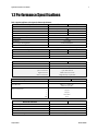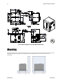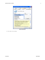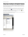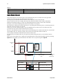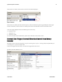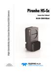
1
GigE Vision Bilinear Color Line Scan Camera 1-Feb-12 03-032-20124-00 www.teledynedalsa.com Spyder3 SG-34 User Manual SG-34-04k80-00-R SG-34-02k80-00-R 2 Spyder3 SG-34 GigE Vision Color Manual © 2012 Teled yne DALSA Inc. All inform ation provid ed in this m anual is believed to be accurate and reliable. No responsibility is assum ed by Teled yne DALSA for its use. Teled yne DALSA reserves the right to make changes to this inform ation w ithout notice. Reprod uction of this manual in whole or in part, by any m eans, is prohibited w ithout prior perm ission having been obtained fr om Teled yne DALSA. About Teledyne Technologies and Teledyne DALSA, Inc. Teled yne Technologies is a lead ing provid er of sophisticated electronic subsystem s, instrum entation and com m unication prod uct s, engineered system s, aerospace engines, and energy and pow er generation system s. Teled yne Technologies’ operations are prim arily located in the United States, the United Kingdom and Mexico. For more inform ation, visit Teled yne Technologies’ w ebsite at w w w.teled yne.com. Teled yne DALSA, a Teled yne Technologies com pany, is an international lead er in high performance d igital im aging and sem icond uctors w ith approxim ately 1,000 em ployees world w id e, headquartered in Waterloo, Ontario, Canad a. Established in 1980, the com pany d esigns, develops, manufactures and markets d igital im aging prod ucts and solution s, in add ition to provid ing MEMS prod ucts and services. For more inform ation, visit Teled yne DALSA’s w ebsite at ww w .teled ynedalsa.com . Support For further inform ation not includ ed in this manual, or for inform ation on Teled yne DALSA’s extensive line of im age sensing prod ucts, please contact: North America Europe Asia Pacific 605 McMurray Rd Waterloo, ON N2V 2E9 Canad a Tel: 519 886 6000 Fax: 519 886 8023 w w w.teled ynedalsa.com sales.am ericas@d alsa.com support@teled ynedalsa.com Breslauer Str. 34 D-82194 Gröbenzell (Munich) Germ any Tel: +49 - 8142 – 46770 Fax: +49 - 8142 – 467746 w w w. teled yned alsa.com sales.europe@teled ynedalsa.com support@teled ynedalsa.com Ikebukuro East 13F 3-4-3 H igashi-Ikebukuro Toshim a-ku, Tokyo 170-0013 Japan Tel: 81 3 5960 6353 Fax: 81 3 5960 6354 (fax) w w w.teled ynedalsa.com sales.asia@teled yned alsa.com support@teled ynedalsa.com Industry Standards Spyd er GEV cam eras are 100% com pliant w ith the GigE Vision 1.0 specification. This specification d efines the com m unication interface protocol used by GigE Vision d evices. For more information on these requirem ents refer to the follow ing site: http:/ / w w w.machinevisiononline.org/ public/ articles/ d etails.cfm ?id =2761 Spyd er GEV cam eras im plem ent a superset of the GenICam™ specification which defines d evice capabilities. This d escription tak es the form of an XML d evice d escription file respecting the syntax d efined by the GenApi m od ule of the GenICam specification. For m ore inform ation on these requirem ents refer to the follow ing site: w w w.genicam .org. 03-032-20124-00 Teledyne DALSA Spyder3 SG-34 GigE Vision Color Manual 3 Contents The Spyder3 SG-34 Cameras ________________________________________________________________ 5 Camera Highlights ............................................................................................................................................................. 5 1.2 Performance Specifications .......................................................................................................................................... 7 Certifications ...................................................................................................................................................................... 9 Image Sensor ..................................................................................................................................................................... 9 Responsivity ....................................................................................................................................................................... 10 Mechanicals........................................................................................................................................................................ 11 Mounting ........................................................................................................................................................................... 12 Software and Hardware Setup .......................................................................................................................................... 13 Setup Steps: Overview ....................................................................................................................................................... 13 Step 1. Ethernet Network Card: Install and Configure ...................................................................................................... 15 Step 2. Connect Power, Ethernet, and Trigger Cables ....................................................................................................... 18 Step 3. Establish Communication with the Camera ........................................................................................................... 22 Using Sapera CamExpert with Spyder3 Cameras .............................................................................................................. 23 Step 4. Camera Test Patterns ............................................................................................................................................ 25 Camera Operation ______________________________________________________________________ 26 Factory Settings ................................................................................................................................................................. 26 Check Camera and Sensor Information ............................................................................................................................. 26 Verify Temperature and Voltage ....................................................................................................................................... 27 Saving and Restoring Camera Settings ............................................................................................................................. 27 Timing: Exposure and Synchronization............................................................................................................................. 29 Exposure Controls .............................................................................................................................................................. 31 Line Rate ........................................................................................................................................................................... 33 Exposure Time ................................................................................................................................................................... 34 Triggers.............................................................................................................................................................................. 34 Input / Output Control ....................................................................................................................................................... 35 Gain, Black Level, and Background .................................................................................................................................. 36 Image Size ......................................................................................................................................................................... 38 Color .................................................................................................................................................................................. 38 Pixel Format ...................................................................................................................................................................... 39 Sensor Direction Control .................................................................................................................................................... 39 Resetting the Camera ........................................................................................................................................................ 40 Camera Calibration ______________________________________________________________________ 41 Calibrating the Camera to Remove Non-Uniformity (Flat Field Correction) ..................................................................... 42 Color Correction Matrix ...................................................................................................................................................... 48 Appendix A: Clear Dark Current _____________________________________________________________ 50 Appendix B: GPIO Control _________________________________________________________________ 57 GPIO Getting Started: Beginner Mode .............................................................................................................................. 57 Examples: Setting the Camera Modes ............................................................................................................................... 59 Outputs .............................................................................................................................................................................. 69 Trigger Settings: GURU Mode ........................................................................................................................................... 71 Teledyne DALSA 03-032-20124-00 4 Spyder3 SG-34 GigE Vision Color Manual PLC Control ........................................................................................................................................................................ 82 Signal Routing Block ......................................................................................................................................................... 87 Appendix C: EMC Declaration _______________________________________________________________ 91 Revision History ________________________________________________________________________ 92 Index________________________________________________________________________________ 93 03-032-20124-00 Teledyne DALSA Spyder3 SG-34 GigE Vision Color Manual 5 The Spyder3 SG-34 Cameras Camera Highlights The Sp yd er3 SG-34 GigE Vision (GEV) are high sensitivity, bilinear scan color cam eras. When op erating in high sensitivity (bilinear) m od e, the Sp yd er3 GEV cam era has 3x the resp onsivity of Teled yne DALSA’s Sp yd er2 line scan cam era. Plu s, the GigE Vision interface elim inates the need for a fram e grabber, resu lting in significant system cost savings. The Sp yd er3 cam eras are su p p orted by Teled yne DALSA Sap era™ softw are libraries featu ring Cam Exp ert for sim p lified cam era set-u p and configu ration. Features and Programmability Single color broad band resp onsivity u p to 79 DN (nJ/ cm 2) @ 20d B gain 2048 or 4096 p ixels, 14 µm x 14 µm (2k) and 10µm x 10µm (4k) p ixel p itch Fill factor 90% (2k) and 86% (4k) Up to 18 KH z (2k) and 9 KH z (4k) line rates Dynam ic range u p to 677 : 1 Data transm ission u p to 100 m ±50 µm x, y sensor alignm ent RoH S and CE com p liant GeniCam com p liant Easy-to-u se GUI Op tional serial interface (ASCII, 57600 bau d , ad ju stable to 19200, 57600, 115200), throu gh virtu al serial p ort throu gh Ethernet (not GeniCam com p liant) Program m able gain, offset, exp osu re tim e and line rate, trigger m od e, test p attern ou tp u t, and cam era d iagnostics Flat-field correction—m inim izes lens vignetting, non -u niform lighting, and sensor FPN and PRN U Description and Applications The Sp yd er3 GigE Vision (GEV) Color cam era is DALSA’s latest GigE Vision cam era. The GigE Vision interface elim inates the need for a fram e grabber, resu lting in significant system cost savings. The Sp yd er3 GEV Color is also DALSA’s first d u al line scan color cam era. The Sp yd er3 GEV Color cam era is id eal for: Cotton and textile insp ection Food , d ru g, and tobacco insp ection Wood , tile, and steel insp ection Postal sorting Recycling sorting 100% p rint insp ection (lottery tickets, stam p s, bank notes, p aychecks) General w eb insp ection Teledyne DALSA 03-032-20124-00 6 Spyder3 SG-34 GigE Vision Color Manual Models The Sp yd er3 GEV color cam era is available in the follow ing configu rations: Table 1: Spyder3 GigE Vision Color Camera Models Overview Model Number SG-34-02K80-00-R SG-34-04K80-00-R Description 2k resolution, 80 MH z d ata rate, 18 KH z line rate. 4k resolution, 80 MH z d ata rate, 9 KH z line rate. Table 2: Software Software Sapera LT, includ ing Cam Expert GUI application QuickCam Pleora Technologies Inc.’s Coyote Third party softw are. E.g. CVB and N I. 03-032-20124-00 Product Number / Version Number Version 7.1 or later. Tested and recom m end ed . Version 2.0. Com pliant. Com pliant. Com patible. Drivers need to be provid ed by the third party. Teledyne DALSA Spyder3 SG-34 GigE Vision Color Manual 7 1.2 Performance Specifications Table 3: Spyder3 GigE Vision Color Camera Performance Specifications Feature / Specification 2k 4k Im ager Form at Resolution Bilinear CCD 1 2048 pixels Pixel Fill Factor Pixel Size 4096 pixels 90 % 86 % 14 µm x 14 µm 10 µm x 10 µm Output Form at (# of taps) 2 Antibloom ing 100x Gain Range 0 to 20 d B Color Output/ Arrangem ent R/ G/ B and Mono Exposure Tim es 3 to 3,000 µs Speed 2k Maxim um Line Rate 4k 18 KH z Minim um Internal Line Rate 9 KH z 300 H z Data Rate 80 MH Z Mechanical Interface 2k Cam era Size 4k 72 m m x 60 m m x 65 m m Mass < 300 g Connectors pow er connector GigE connector GPI/ O connector 6 pin m ale H irose RJ45 w ith screw locks H igh d ensity 15-pin d sub Optical Interface Back Focal Distance 6.56 ± 0.25 m m Lens Mounts M42 x 1, C and F (2k) M58 x 0.75, F (4k) Sensor Alignm ent x y z z ±50 µm ±50 µm ±0.25 m m ±0.2° Electrical Interface Input Voltage +12 V to +15 V Pow er Dissipation < 10.5 W Operating Tem perature 0 to 50 °C Bit Wid th Output Data Configuration Teledyne DALSA 8 bit GigE Vision 03-032-20124-00 8 Spyder3 SG-34 GigE Vision Color Manual Notes 1. The interpolation proced u re d oes not w ork on the first and last pixels; as a resu lt, t he nu m ber of effective fu ll color (RGB) p ixels for the 2k and 4k cam eras is red u ced by 2 to 2046 or 4094 respectively. Table 4: Camera Operating Specifications (Single Color) Specifications Unit 0 dB Min Typ Broad band responsivity Max Min 10 dB Typ Max Min 20 dB Typ DN / (nJ/ cm ²) 2k 7.9 25 79 4k 4 12.6 40 Rand om noise rm s Max DN 2k 4k 0.75 Dynam ic range DN :DN FPN global DN p -p 335 677 106 0.788 1.56 2.5 5 1.19 2.38 3.75 7.5 214:1 33:1 67.7:1 Uncorrected 4 12.5 40 Corrected 2 2 4 PRN U ECD Uncorrected local % 8.5 Uncorrected global % 10 Corrected local DN p -p 5 Corrected global DN p -p 5 Uncorrected local % 8.5 Uncorrected global % 10 Corrected local DN p -p 5 Corrected global DN p -p 5 SEE (calculated ) nJ/ cm ² PRN U ECE 2k 32.2 10.1 3.21 4k 64.3 20.2 6.43 2k 31.7 31.7 31.7 4k 95 95 95 N EE (calculated ) pJ/ cm ² Saturation output am plitud e DN DC offset DN 255 2 5 5 5 Test conditions unless otherwise noted: 8-bit valu es, Flat Field Correction (FFC) enabled . CCD Pixel Rate: 40 MH z p er sensor tap Line Rate: 5000 H z N om inal Gain setting u nless otherw ise sp ecified 03-032-20124-00 Teledyne DALSA Spyder3 SG-34 GigE Vision Color Manual 9 Light Sou rce: Broad band Qu artz H alogen, 3250k, w ith 750 nm highp ass filter installed Am bient test tem p eratu re 25 °C Exp osu re m od e d isabled . Unless sp ecified , d u al line m od e. N otes: PRN U m easu red at 50% SAT. Certifications Table 5: EMC Compliance Standards Compliance The CE Mark, FCC Part 15, and Ind ustry Canad a ICES-003 Evaluation of the DALSA Spyd er GigE SG-34 cam eras m eet the follow ing requirem ents: EN 55022 Class A, and EN 61326 Em issions Requirem ents, EN 55024, and EN 61326 Im m unity to Disturbances Image Sensor This color bilinear cam era is based on DALSA’s bilinear CCD sensor. The first line of this tw o line sensor has red (R) and blu e (B) alternating p ixels, w hile the second line has all green (G) p ixels. There is no gap in betw een the tw o lines and this m inim izes any artifact d u e to sp atial correction. The G channel can be u sed as a m onochrom e ou tp u t. The sensor has a 2 tap ou tp u t. Figure 1: Bilinear sensor used in Spyder3 Color (block diagram) CCD Readout Shift Register N Pixels (14 µm x 14 µm or 10 µm x 10 µm) R G B G R G B G R G B G R G B G R G B G R G B G N Pixels (14 µm x 14 µm or 10 µm x 10 µm) CCD Readout Shift Register N= 2048, 4096 Pixel 1, 1 Please note that interp olation p roced u re d oes not w ork on the first and last p ixels; as a resu lt, the nu m ber of effective fu ll color (RGB) p ixels for the 2k and 4k cam eras is red u ced by 2 to 2046 or 4094 resp ectively. Teledyne DALSA 03-032-20124-00 10 Spyder3 SG-34 GigE Vision Color Manual Responsivity Figure 2: Spyder3 GigE Vision Responsivity Spyder3 2k GEV Color Responsivity [DN/(nj/cm2)] 100 Blue 90 Green 80 Red 70 60 50 40 30 20 10 0 400 450 500 550 600 650 700 750 800 850 900 950 1000 1050 1100 Wavelength [nm] Spyder3 4k GEV Color Responsivity [DN/(nj/cm2)] 40 Series1 35 Series2 Series3 30 25 20 15 10 5 0 400 450 500 550 600 650 700 750 800 850 900 950 1000 1050 1100 Wavelength [nm] 03-032-20124-00 Teledyne DALSA Spyder3 SG-34 GigE Vision Color Manual 11 Mechanicals Figure 3: Spyder3 2k GigE Vision Color Camera Mechanical Dimensions Teledyne DALSA 03-032-20124-00 12 Spyder3 SG-34 GigE Vision Color Manual Figure 4: Spyder3 4k GigE Vision Color Camera Mechanical Dimensions Mounting H eat generated by the cam era m u st be allow ed to m ove aw ay from the cam era. Mou nt the cam era on the frontp late (u sing the p rovid ed m ou nting holes) w ith m axim u m contact to the area for best heat d issip ation. Figure 5: Spyder3 Mounting Example 03-032-20124-00 Teledyne DALSA Spyder3 SG-34 GigE Vision Color Manual 13 Software and Hardware Setup Host System Requirements To achieve best system p erform ance, the follow ing m inim u m resqu irem ents are recom m end ed : Op erating system : Wind ow s XP Professional, Wind ow s Vista, Wind ow s 7 (either 32-bit or 64-bit for all) are su p p orted . Network Adapter Requirements GigE netw ork ad ap ter (either PCI card or LOM): For high p erform ance you m u st u se a Intel PRO/ 1000 MT ad ap ter. The Sp yd er3 GEV cam era w orks only w ith netw ork ad ap ters based on the Intel 82546, 82541, and 82540 netw ork chip s. The d river w ill also fu nction w ith ad ap ters based on the Intel 82544 chip , bu t these are not recom m end ed d u e to bu gs in the chip that can cau se control p ackets to be lost if sent w hile d ata is stream ing. Ethernet Switch Requirements When you requ ire m ore than one d evice on the sam e netw ork or a cam era -to-PC sep aration of m ore than 100 m etres, you can u se an Ethernet sw itch. Since the Sp yd er3 GEV cam era com p lies w ith the Internet Protocol, the cam era shou ld w ork w ith all stand ard Ethernet sw itches. H ow ever, sw itches offer a range of fu nctions and p erform ance grad es, so care m u st be taken to choose the right sw itch for a p articu lar ap p lication. Setup Steps: Overview Take the follow ing step s in ord er to setu p and ru n you r cam era system . They are d escribed briefly below and in m ore d etail in the follow ing sections. 1. Install and Configure Ethernet Network Card If you r host com p u ter d oes not have a Gigabit netw ork ad ap ter or equ ivalent (PCI bu s Gigabit N IC) alread y installed , then you need to install on e. For Gigabit p erform ance w e recom m end the Intel PRO/ 1000 MT ad ap ter, or equ ivalent. Follow the m anu factu rer’s installation instru ctions. A GigE Vision com p liant XML d evice d escrip tion file is em bed d ed w ithin the cam era’s firm w are allow ing GigE Vision com p liant ap p lications (e.g. Qu ickCam , Pleora`s Coyote, and Sap eraLT) to know the cam era’s cap abilities im m ed iately after connection. The Sp yd er3 cam era w as tested w ith and su p p orts Sap eraLT w hich gives you access to the Cam Exp ert GUI, a GigE Vision com p liant ap p lication. Software Installation Install Sapera LT w ith CamExpert to control the Sp yd er3. You can access Sap era d rivers, SDKs, and d em os from the follow ing link: http :/ / w w w .teled yned alsa.com / m v/ su p p ort/ d riverSDKlist.asp x Teledyne DALSA 03-032-20124-00 14 Spyder3 SG-34 GigE Vision Color Manual 2. Connect Power, Ethernet and I/O Cables Connect a p ow er cable from the cam era to a +12 VDC to +15 VDC p ow er su p p ly. Connect the Ethernet cable from the cam era to the com p u ter Ethernet jack. If u sing the external signals connect the external control cable to the cam era. 3. Establish communicating with the camera Start the GUI and establish com m u nication w ith the cam era. 4. Check camera LED, settings and test pattern Ensu re that the cam era is op erating p rop erly by checking the LED, the cu rrent settings, and by acqu iring a test p attern. 5. Operate the Camera At this p oint you w il be read y to op erate the cam era in ord er to acqu ire and retrieve im ages, set cam era fu nctions, and save settings. 03-032-20124-00 Teledyne DALSA Spyder3 SG-34 GigE Vision Color Manual 15 Step 1. Ethernet Network Card: Install and Configure Install Network Card The follow ing netw ork card has been tested and is recom m end ed for u se w ith this cam era: Intel Pro/ 1000 MT Desktop Ad ap ter (33-MH z, 32-bit PCI). Ord er Cod e: PWLA8391GT (single p acks). Follow the m anu factu rer’s recom m end ations to install this card in the host PC. Configure Network Card The configu ration show n here u ses the Wind ow s XP op erating system as the host p latform . The cam era com m u nicates u sing the Ethernet connection and em p loys the static IP ad d ress: 192.168.5.100 (d efau lt). A static ad d ress ensu res the fastest op eration. Alternatively, you can u se a d ynam ic IP ad d ress. To configu re the netw ork card from the host PC: 1. 2. 3. In the Start m enu u nd er ―Control Panel‖ select ―N etw ork Connections,‖ and configu re the netw ork card as follow s: Select the installed netw ork card and click on ―Change settings of this connection.‖ Enable the ―Internet Protocol (TCP/ IP)‖ op tion only. Figure 6. Internet Protocol Teledyne DALSA 03-032-20124-00 16 Spyder3 SG-34 GigE Vision Color Manual 4. 5. 6. With ―Internet Protocol (TCP/ IP)‖ selected , click on the ―Prop erties‖ bu tton. Select ―Use the follow ing IP ad d ress‖ and set the IP ad d ress to any ad d ress in this su bnet other than 192.168.5.100, w hich is u sed by the cam era. In the exam p le below , the ad d ress 192.168.5.50 is u sed . Alternatively, select ―Obtain an IP ad d ress au tom atica lly‖ to u se a d ynam ic ad d ress. Set su bnet to: 255.255.255.0 and click on ―OK.‖ Figure 7. IP Address 7. 8. 9. Click ―OK‖ to save settings Click on ―Configu re‖ bu tton and select ―Ad vanced ‖ tab Enable ―Ju m bo Fram es‖ to greater than 9000 bytes. If you r N IC d oes not su p p ort ju m bo p ackets the im age transfer sp eed w ill be slow er. 03-032-20124-00 Teledyne DALSA Spyder3 SG-34 GigE Vision Color Manual 17 Figure 8. Jumbo Frames 10. Click ―OK‖ to save settings Teledyne DALSA 03-032-20124-00 18 Spyder3 SG-34 GigE Vision Color Manual Step 2. Connect Power, Ethernet, and Trigger Cables WARN IN G! Grounding Instructions Static electricity can d am age electronic com p onents. Please d ischarge any static electrical charge by tou ching a grou nd ed su rface, su ch as the m etal com p u ter chassis, before p erform ing any hard w are installation. ! The u se of cables typ es and lengths other than those sp ecified m ay resu lt in increased em ission or d ecreased im m u nity and p erform ance of the cam era. Figure 9: Input and Output, trigger, and Power Connectors Power Connector ! WARN IN G: It is extrem ely im p ortant that you ap p ly the ap p rop riate voltages to you r cam era. Incorrect voltages m ay d am age the cam era. Inp u t voltage requ irem ent: +12 V to +15 V DC. Hirose 6-pin Circular Male 6 1 5 2 4 3 Pin Description 1, 2, 3 Supply voltage—Min +12 VDC to Max +15 VDC 4, 5, 6 Ground Mating Part: HIROSE HR10A-7P-6S Table 6. Hirose 6-Pin Power Pinout The cam era requ ires a single 6-p in H irosie connector w ith a single voltage inp u t +12 VDC to +15 VDC for p ow er. The cam era m eets all p erform ance sp ecifications u sing stand ard sw itching p ow er su p p lies, althou gh w ell-regu lated linear su p p lies p rovid e op tim u m p erform ance. 03-032-20124-00 Teledyne DALSA Spyder3 SG-34 GigE Vision Color Manual 19 WARNING: When setting up the camera’s power supplies follow these guidelines ! Ap p ly the ap p rop riate voltages. Protect the cam era w ith a 2 am p slow -blow fu se betw een the p ow er su p p ly and the cam era. Do not u se the shield on a m u lti-cond u ctor cable for grou nd . Keep lead s as short as p ossible in ord er to red u ce voltage d rop . Use high-qu ality linear su p p lies in ord er to m inim ize noise. Note: If your power supply does not meet these requirements, then the camera performance specifications are not guaranteed. Ethernet Connector and Ethernet LED The cam era u ses an RJ45 connector and a stand ard Cat 5 cable for Gigabit Ethernet signals and serial com m u nications. The d evice su p p orts 10/ 100/ 1000 Mbit/ s sp eed s. N ote: Rou ter connection not su p p orted . Connection to a netw ork sw itch for a single cam era is su p p orted . Data Transmission LED Ethernet Connection LED@ 1Gbps Ethernet Connection LED Stead y ON ind icates that an Ethernet connection is su ccessfu lly established at 1Gbp s. Data Transmission LED Stead y ON ind icates that the cam era is read y for d ata transm ission. Flashing ind icates that the cam era is transm itting or receiving d ata. EMC Compliance In ord er to achieve EMC com p liance, the Sp yd er3 cam era requ ires the u se of shield ed CAT5e or CAT6 Ethernet cables. Status LED The cam era is equ ip p ed w ith a red / green LED u sed to d isp lay the statu s of the cam era's op eration. The table below su m m arizes the op erating states of the cam era and the corresp ond ing LED states. When m ore than one cond ition is active, the LED ind icates the cond ition w ith the highest p riority. Error and w arning states are accom p anied by corresp ond ing m essages that fu rther d escribe the cu rrent cam era statu s. Priority Color of Status LED Meaning 1 Flashing Red 2 3 Flashing Green Solid Green Teledyne DALSA Fatal Error. For exam ple, cam era tem perature is too high and cam era therm al shutd ow n has occurred . Cam era initialization or executing a long com m and . Cam era is operational and functioning correctly. 03-032-20124-00 20 Spyder3 SG-34 GigE Vision Color Manual GPIO Connector: A single 15-p in general p u rp ose inp u t / ou tp u t (GPIO) connector is u sed to receive or control external signals. For exam p le, the GPIO connector can be u sed to receive EXSYN C, PRIN (p ixel reset), and d irection signals. External Inp u t The GPIO connector is p rogram m ed throu gh the GUI ap p lication. In Cam Exp ert the relevant p aram eters are located in the category Inp u ts Grou p . Figure 10: GPIO Connector and Pin Numbers 1 5 15 11 Table 7: GPIO Connector Pinout Pin 1 2 3 4 5 6 7 8 9 10 11 12 13 14 15 Signal INPUT_ 0+ INPUT_0INPUT_1+ INPUT_1GND INPUT_2+ INPUT_2INPUT_3 OUTPUT_3 OUTPUT_2+ OUTPUT_0+ OUTPUT_0OUTPUT_1+ OUTPUT_1OUTPUT_2- Description GenICam Default LVDS/TTL format (positive) LVDS (negative) LVDS/TTL format (positive) LVDS (negative) EXSYNC + EXSYNC FrameTrig + FrameTrig - LVDS/TTL format (positive) LVDS (negative) TTL auxiliary input TTL auxiliary output LVDS/TTL auxiliary output LVDS/TTL auxiliary output LVDS (negative) LVDS/TTL auxiliary output LVDS (negative) LVDS (negative) Direction + Direction - A schem atic of the TTL inpu t circu itry is show n below . The inpu t signals are fed into the engine from external sou rces via the GPIO connector. GPIO Isolation All of the GPIOs are isolated from the rest of the cam era and the cam era case. They are not isolated w ith resp ect to each other and share a com m on retu rn (grou nd ) throu gh p in 5 of the GPIO connector. N ote: The shell connection of the GPIO connector is not isolated and it shou ld not be u sed as a retu rn (grou nd ) for the GPIO signals. The shell connection is attached to the cam era case. GPIO Configuration Refer to Ap pend ix C: GPIO Control for a d etailed d escription of the GPIO u se-cases and configu ration options. 03-032-20124-00 Teledyne DALSA Spyder3 SG-34 GigE Vision Color Manual 21 TTL Inputs and Outputs Figure 11: TTL Input Schematic 3.3V 1000 3.3V TTL Term ination: 1000 Ω series Inp u t cu rrent: m inim u m 0 nA; m axim u m 2 m A Inp u t voltage: m axim u m of low 0.66 V; m inim u m of high 2.6 V TTL inp u ts are m axim u m 5 V and 3.3 V logic tolerant Figure 12: TTL Output Schematic 100 5V ESD Protection Term ination: 100 Ω series Ou tp u t cu rrent: sink 50 m A; sou rce 50 m A Ou tp u t voltage: m axim u m of low 0.55 V @ 32m A; m inim u m of high 3.8 V @ 32m A. LVDS Inputs and Outputs (LVDS compliant) Figure 13: LVDS Input 100 Figure 14Figure 15: LVDS Output Teledyne DALSA 03-032-20124-00 22 Spyder3 SG-34 GigE Vision Color Manual Step 3. Establish Communication with the Camera Power on the camera Tu rn on the cam era’s p ow er su p p ly. You m ay have to w ait u p to 60 second s w hile the cam era w arm s u p and p rep ares itself for op eration. Connect to the camera 1. Start a new Sap era Cam Exp ert ap p lication (or equ ivalent GigE Vision com p liant interface) by d ou ble clicking the d esktop icon created d u ring the softw are installation. 2. Cam Exp ert w ill search for installed Sap era d evices. In the Devices list area on the left sid e, the connected Sp yd er cam era w ill be show n. 3. Select the Sp yd er cam era d evice by clicking on the cam era u ser -d efined nam e. By d efau lt the cam era is id entified by its serial nu m ber. Check LED Status If the cam era is op erating correctly at this p oint, the d iagnostic LED w ill flash for 10 second s and then tu rn solid green. Software Interface All the cam era featu res can be controlled throu gh the Cam Exp ert interface. For exam p le, u nd er the Sensor Control m enu in the cam era w ind ow you can control the fram e rate and exp osu re tim es. 03-032-20124-00 Teledyne DALSA Spyder3 SG-34 GigE Vision Color Manual 23 Using Sapera CamExpert with Spyder3 Cameras Cam Exp ert is the cam era interfacing tool su p p orted by the Sap era library. When u sed w ith a Sp yd er3 cam era, Cam Exp ert allow s a u ser to test all Sp yd er3 op erating m od es. Ad d itionally Cam Exp ert saves the Sp yd er3 u ser settings configu ration to the cam era or saves m u ltip le configu rations as ind ivid u a l cam era p aram eter files on the host system (*.ccf). An im p ortant com p onent of Cam Exp ert is its live acqu isition d isp lay w ind ow w hich allow s im m ed iate verification of tim ing or control p aram eters w ithou t the need to ru n a sep arate acqu isition p rogram . For context sensitive help , click on the bu tton then click on a cam era configu ration p aram eter. A short d escrip tion of the configu ration p aram eter w ill be show n in a p op u p . Click on the op en the help file for m ore d escrip tive inform ation on Cam Exp ert. bu tton to The central section of Cam Exp ert p rovid es access to the Sp yd er3 p aram eters. N ote: The availability of the p aram eters is d ep end ent on the Cam Exp ert u ser setting. CamExpert Panes Figure 16: CamExpert Example Teledyne DALSA 03-032-20124-00 24 Spyder3 SG-34 GigE Vision Color Manual The Cam Exp ert ap p lication u ses 5 w ind ow s to sim p lify choosing and configu ring cam era files or acqu isition p aram eters for the installed d evice. D evice Selector pane: View and select from any installed Sap era acqu isition d evice. Once a d evice is selected Cam Exp ert w ill only p resent acqu isition p aram eters ap p licable to that d evice. Op tionally select a cam era file inclu d ed w ith the Sap era installation or saved by the u ser. Parameters pane: Allow s view ing or changing all acqu isition p aram eters su p p orted by the acqu isition d evice. Cam Exp ert d isp lays p aram eters only if those p aram eters are su p p orted by the installed d evice. This avoid s confu sion by elim inating p aram eter choices w hen they d o no t ap p ly to the hard w are in u se. D isplay pane: Provid es a live or single fram e acqu isition d isp lay. Fram e bu ffer p aram eters are show n in an inform ation bar above the im age w ind ow . Control Buttons: The Disp lay p ane inclu d es Cam Exp ert control bu ttons. These are: Acquisition control button: Click once to start live grab, click again to stop. Single frame grab: Click to acquire one frame from device. Software trigger button: With the I/O control parameters set to Trigger Enabled / Software Trigger type, click to send a single software trigger command. CamExpert display controls: (these do not modify the frame buffer data) Stretch image to fit, set image display to original size, or zoom the image to any size and ratio. Histogram / Profile tool: Select to view a histogram or line/column profile during live acquisition. Output Message pane: Disp lays m essages from Cam Exp ert or the d evice d river. 03-032-20124-00 Teledyne DALSA Spyder3 SG-34 GigE Vision Color Manual 25 Step 4. Camera Test Patterns Review a Test Pattern Image The cam era is now read y to retrieve a test p attern. The Sp yd er3 cam eras inclu d e a bu ilt -in test p attern generator that can be u sed to confirm cam era Ethernet connections w ithou t the need for a cam era lens or p rop er lighting. The test p atterns are u sefu l for verifying cam era tim ing and connections, and to aid in system trou ble shooting. Using Cam Exp ert, select Image Format Control > Test Image Selector and choose one of the available test im ages. Select live grab to see the p attern ou tp u t. The follow ing test p atterns are available: Figure 17. Grey horizontal step Figure 18. Grey horizontal ramp Teledyne DALSA 03-032-20124-00 26 Spyder3 SG-34 GigE Vision Color Manual At this p oint you are read y to start op erating the cam era in ord er to acqu ire im ages, set cam era fu nctions, and save settings. Camera Operation Factory Settings The cam era ship s and p ow ers u p for the first tim e w ith the follow ing factory settings: Forw ard CCD shift d irection 8 bit, 2 tap N o binning Exp osu re m od e: internal sync & m axim u m exp osu re tim e 5, 000 H z line rate Factory calibrated analog gain and offset Factory calibrated FPN and PRN U coefficients Check Camera and Sensor Information Camera and sensor information can be retrieved via a controlling application—in the examples shown here, CamExpert. Parameters such as camera model, firmware version, sensor characteristics, etc. are read to uniquely identify the connected device. The cam era inform ation p aram eters are grou p ed together as m em bers of the Cam era Inform ation set. GigE Vision Input Controls Camera Information Parameter Options Manufacturer N am e Mod el N am e Manufacturer Info Device Version Read Only Parameters Device ID Device User ID Define a cam era nam e up to 64 characters Serial num ber Read Voltage and Tem perature Click to read the voltage from the cam era. In general, the tem perature read is 15 C greater than the tem perature at the front plate. The tem perature should not exceed 80 °C. Input Voltage 03-032-20124-00 Teledyne DALSA Spyder3 SG-34 GigE Vision Color Manual 27 Verify Temperature and Voltage To d eterm ine the voltage and tem p eratu re at the cam era, u se the Read Voltage and Temperature featu re fou nd in the Camera Information set. The tem p eratu re retu rned is the internal chip case tem p eratu re in d egrees Celsiu s. For p rop er op eration, this valu e shou ld not exceed 80 °C. If the cam era exceed s the d esignated tem p eratu re it w ill shu t d ow n and w ill not tu rn on u ntil the cam era’s tem p eratu re is 73 ºC or less. Use the reset camera fu nction. The voltage d isp layed is the cam era’s inp u t voltage. N ote that the voltage m easu rem ent featu re of the cam era p rovid es only ap p roxim ate resu lts (typ ically w ithin 10%). The m easu rem ent shou ld not be u sed to set the ap p lied voltage to the cam era, bu t only u sed as a test to isolate gross p roblem s w ith the su p p ly voltage. Saving and Restoring Camera Settings The p aram eters u sed to select, load an d save u ser sets are grou p ed together u nd er the Cam era Inform ation set of featu res. GigE Vision Input Controls Camera Information Parameter User Set Selector / Device Configuration Selector User Set Load / Load Configuration User Set Save / Save Configuration Description Selects the cam era configuration set to load feature settings from or save current feature settings to: factory (d efault) or user sets. The Factory / Default set contains d efault cam era feature settings. User cam era configuration sets contain feature settings previously saved by the user. Load the set specified by User Set Selector to the cam era and m ake it the active / current set. Save the current set as selected user set. Description of the Camera Settings The cam era op erates in one of three settings: 1. 2. 3. Cu rrent session User setting Factory setting (Defau lt, read -only) The cu rrent settings can be saved (thereby becom ing the u ser setting) u sing the User Set Save p aram eter. A p reviou sly saved u ser setting (User Set 1) or the factory settings can be restored u sing the User Set Selector and User Set Load p aram eters. The relationship betw een these three settings is illu strated here and d escribed below : Teledyne DALSA 03-032-20124-00 28 Spyder3 SG-34 GigE Vision Color Manual Figure 19. Relationship between the Camera Settings Current Session Active Setting The active setting for the cu rrent session is the set of configu rations that are op erating w hile the cam era is cu rrently ru nning, inclu d ing all u nsaved changes you have m ad e to the settings before saving them . These active settings are stored in the cam era’s volatile m em ory and w ill be lost and cannot be restored if the cam era resets or if the cam era is p ow ered d ow n or loses p ow er. To save these settings for reu se the next tim e you p ow er u p or reset the cam era, or to p rotect agai nst losing them in the case of p ow er loss, you m u st save the cu rrent settings u sing the User Set Save p aram eter. Once saved , the cu rrent settings becom e you r User Set 1. User Setting The u ser setting is the saved set of cam era configu rations that you can cu stom ize, resave, and restore. By d efau lt the u ser settings are ship p ed w ith the sam e settings as the factory set. The com m and User Set Save saves the cu rrent settings to non -volatile m em ory as a User Set. The cam era au tom atically restores the last saved u ser settings w hen it resets and / or p ow ers u p . To restore the last saved u ser settings, select the User Set p aram eter you w ant to restore and then select the User Set Load p aram eter. Factory (Default) Settings The d efau lt settin g is the cam era settings that w ere ship p ed w ith the cam era and w hich load ed d u ring the cam era’s first p ow er-u p . To load or restore the original factory settings, at any tim e, select the D efault / Factory Setting p aram eter and then select the User Set Load p aram eter. Please note that the follow ing p aram eters are not reset w hen you load / restore the factory settings: 03-032-20124-00 Debou nce selector Calibrate White Balance Target PRN U Calibration Target Color Correction Inp u t Channel Color Correction Ou tp u t Channel Tap Teledyne DALSA Spyder3 SG-34 GigE Vision Color Manual 29 Color Also note: By d efau lt, the u ser settings are set to the factory settings. Timing: Exposure and Synchronization Im age exp osu res are initiated by an event. The trigger event is either the cam era's p rogram m able internal clock u sed in free ru nning m od e, an external inp u t u sed for synchronizing exp osu res to external triggers, or a p rogram m ed fu nction call m essage by the controlling com p u ter. Trigger com m and s are available as m em bers of the Line Trigger set. GigE Vision Input Controls Line Trigger Line Trigger Mod e Line Trigger Sou rce Line Trigger Activation External Line Trigger Frequ ency The state of the line trigger. If OFF, then the line trigger is internally generated . If ON , then triggered by an external signal. The external sou rce that cau ses a line trigger. The line trigger is from the GPIO_PIN 0. This featu re is available only w hen Line Trigger Mod e is set to ON . Determ ines the typ e of signal (high or low ) that w ill cau se a line trigger. Line Trigger Mod e m u st be ON . Read s the external line trigger frequ ency. N OTE: The cam era cannot d etect frequ ency less than 5 H z and w ill d isp lay 1 if it cannot d etect a signal. This featu re is available w hen the Line Trigger Mod e is set o ON and Sensor Direction Control is set to External. The three trigger m od es are d escribed here: Free running (trigger disabled): The cam era free-ru nning m od e has a p rogram m able internal tim er for line rate and a p rogram m able exp osu re p eriod . Line rate is 0.1 fp s to the m axim u m su p p orted by the sensor. Exp osu res range from the sensor m inim u m to a m axim u m also d ep end ent on the cu rren t line rate. This alw ays u ses Synchronou s m od e w here exp osu re is aligned to the sensor horizontal line tim ing. External trigger: Exp osu res are controlled by an external trigger signal. External signals are isolated by an op to-cou p ler inp u t w ith a tim e p rogram m able d ebou nce circu it. The follow ing section p rovid es inform ation on external trigger tim ing. Softw are trigger: An exp osu re trigger is sent as a control com m and via the netw ork connection. Softw are triggers can not be consid ered tim e accu rate d u e to netw ork latency and sequ ential com m and jitter. Bu t a softw are trigger is m ore resp onsive than calling a single -line acqu isition (Snap com m and ) since the latter m u st valid ate the acqu isition p aram eters and m od ify on -board bu ffer allocation if the bu ffer size has changed since the last acqu isition. Teledyne DALSA 03-032-20124-00 30 Spyder3 SG-34 GigE Vision Color Manual Timing tLine Period twSYNC twSYNC_INT EXSYNC tPR_INT tPR twPR_HIGH twPR_LOW PRIN tTRANSFER tREADOUT tOVERHEAD Internal Line Valid tEthernet Latency Valid Data From Diagramed ExSync Ethernet Latency to PC Memory Table 8: Timing Parameter Table Units tLine_Period μs tw Sync tw SYN C_IN T ns ns tPR ns tw PR_LOW ns tw PR_H IGH ns tPR_IN T ns Table 9: tReadout Values tREADOUT Sensor Size 1024 1 1024 2 2048 1 2048 2 4096 2 Table 10: tOverhead Values tOVERHEAD Sensor Size 1024 1024 2048 2048 03-032-20124-00 Min. 27.78 14.71 54.1 27.78 54.1 100 100 (3000*) 0 3000 3000 3000 Typ. Max. 1000 1000 1000 1000 1000 Notes 1K 1 Tap 1K 2 Tap 2K 1 Tap 2K 2 Tap 4k 2 Tap For exp osu re m od e 4 this valu e need s to be >3000ns other w ise >100ns # Taps Readout Time 25600ns 12800ns 51200ns 25600ns # Tap s 1 2 1 2 Read ou t Tim e 725ns 450ns 1400ns 725ns Teledyne DALSA Spyder3 SG-34 GigE Vision Color Manual 31 Overhead Delay Overhead _Delay can range from 5 to 6μs and d ep end s on the internal op erations of you r com p u ter. Exposure Controls The cam era can grab im ages in one of seven w ays. The cam era’s line rate (synchronization) can be generated internally throu gh the Acquisition Line Rate featu re (a m em ber of the Sensor Control set of featu res) or set externally w ith an EXSYN C signal, d ep end ing on you r m od e of op eration. To select how you w ant the cam era’s line rate to be generated : 1. 2. First set the cam era m od e using Exposure Mode and Line Trigger Mode com m and s. N ext, if using m od e 2, 6, or 7 (see below ) use the com m and s Acquisition Line Rate Abs and / or Exposure Time Abs to set the line rate and exposure tim e. GigE Vision Input Controls Sensor Control Exp osu re Mod e This featu re is u sed to set the op eration m od e of the Exp osu re (or shu tter): Off, Tim ed , Trigger Wid th. If Off is selected then the cam era u ses the m axim u m tim e accord ing to its line rate. Line Trigger Group Line Trigger Mod e The state of the line trigger. If the trigger is off, then the line trigger is internally generated . Otherw ise, the line trigger is cau sed by an external signal. Mod es: Off or On. Set the Exposure Mode Sets the cam era’s exp osu re m od e allow ing you to control you r sync, exp osu re tim e, and line rate generation. Programmable Line Rate Programmable Exposure Time Mode LineTriggerMode ExposureMode Description A Off (Internal) Tim ed (Internal) Yes Yes Internal line rate and exposure tim e. Exposure m od e enabled . B On (External) Off (Internal) No No Maxim um exposure tim e. Exposure m od e d isabled . C On (External) TriggerWid th (Internal) No No Sm art EXSYN C. Exposure m od e enabled . D On (External) Tim ed (Internal) No Yes Fixed integration tim e. Exposure m od e enabled . E Off (Internal) Off (Internal) Yes No Internal line rate, m axim um exposure tim e. Exposure m od e d isabled . N ote: When setting the cam era to external signal m od es EXSYN C m u st be su p p lied . Exposure Modes in Detail Mode A. Internally Programmable Line Rate and Exposure Time (Factory Setting): ExposureMode Timed and LineTriggerMode Off (Internal Teledyne DALSA 03-032-20124-00 32 Spyder3 SG-34 GigE Vision Color Manual Operates at a m axim u m line rate and exposu re tim e. ) When setting the line rate (u sing the AcquisitionLineRateAbs com m and ), exposu re tim e w ill be red u ced , if necessary, to accom m od ate the new line rate. The exposu re tim e w ill alw ays be set t o the m axim u m tim e (line period – line transfer tim e – pixel reset tim e) for that line rate w hen a new line rate requ iring red u ced exposu re tim e is entered . When setting the exposu re tim e (u sing the ExposureTimeAbs com m and ), line tim e w ill be increased , if necessary, to accom m od ate the exposu re tim e. Und er this cond ition, the line tim e w ill equ al the exposu re tim e + line transfer tim e. Example 1: Exposure Time less than Line Period Programmable Period (ExposureTimeAbs command) Waiting Readout CR Exposure Time Programmable Period Waiting Readout Line Period CR Exposure Time Line Period Programmable Period Programmable Period (AquisitionLineRateAbs command) CR=Charge Reset Mode B. External Trigger with Maximum Exposure: ExposureMode Off and LineTriggerMode On (External) Line rate is set by the period of the external trigger pu lses. The falling ed ge of the external trigger m arks the beginning of the exposu re. Example 2: Line Rate is set by External Trigger Pulses. Line Period Line Period Readout Readout Exposure Time Exposure Time EXSYNC Falling Edge Ignored During Readout Falling Edge Ignored During Readout Mode C. Smart EXSYNC, External Line Rate and Exposure Time: ExposureMode TriggerWidth and LineTriggerMode On (External) In this m od e, EXSYN C sets both the line period and the exposu re tim e. The rising ed ge of EXSYN C m arks the beginning of the exposu re and the falling ed ge initiates read ou t. Example 3: Trigger Period is Repetitive and Greater than Read Out Time. Line Period CR Exposure Time Line Period Readout Waiting CR Exposure Time Readout Waiting EXSYNC CR=Charge Reset 03-032-20124-00 EXSYNC falling edge ignored during readout EXSYNC falling edge ignored during readout Teledyne DALSA Spyder3 SG-34 GigE Vision Color Manual 33 Mode D. External Line Rate and Internally Programmable Exposure Time: ExposureMode Timed and LineTriggerMode On (External) Figure 20: EXSYNC controls Line Period with Internally controlled Exposure Time Line Period Exposure Time CR Line Period Readout Waiting Programmable period using ExposureTimeAbs command CR Exposure Time Readout Waiting Programmable period using ExposureTimeAbs command EXSYNC CR=Charge Reset Mode E. Internally Programmable Line Rate, Maximum Exposure Time: ExposureMode Off and LineTriggerMode Off (Internal) In this m od e, the line rate is set internally w ith a m axim u m exposu re tim e. Figure 21: Mode 7 Camera Timing Line Period Line Period Exposure Time Exposure Time Readout Readout Internal Sync set with AquisitionLineRateAbs command EXSYNC falling edge ignored during readout EXSYNC falling edge ignored during readout Line Rate To set the cam era’s line rate, u se the Line Rate featu re fou nd in the Sensor Control set. This featu re is only available w hile the cam era is op erating in Internal Imaging Mode (Trigger Mod e off). GigE Vision Input Controls Sensor Control Parameter Line Rate (H z) Description Cam era line rate, in H z. 300 H z m in., 68000 H z m ax. Only available w hen the cam era is in Internal Mod e—trigger is d isabled (Trigger Mod e off). Exp osu re Mod e is Tim ed and Line Trigger Mod e is ON . Line rates are in the following configurations: 2k 1 tap: 300-18500 Hz 2k 2 tap: 300-36000 Hz 4k 2 tap: 300-18500 Hz Teledyne DALSA 03-032-20124-00 34 Spyder3 SG-34 GigE Vision Color Manual Exposure Time To set the cam era’s exp osu re tim e, u se the Exposure Time featu re fou nd in the Sensor Control set. This featu re is u sed to set the exp osu re tim e in µs. This featu re is only available w hen the Timed Exposure Mode. The allow able range is from 3 µs to 3300 µs. GigE Vision Input Controls Sensor Control Parameter Exp osu re Mod e Exp osu re Tim e Description This featu re is u sed to set the op eration m od e of the Exp osu re (or shu tter): Timed, Trigger Wid th, Off (m axim u m , accord ing to line rate). This featu re is u sed to set the Exp osu re tim e (in m icrosecond s) w hen Exp osu re Mod e is set to Tim ed . m in 3, m ax 3300 u s. Triggers GigE Vision Input Controls Frame Trigger Function Group The Fram e Trigger Control section d escribes all featu res related to fram e acqu isition u sing trigger(s). One or m any Trigger(s) can be u sed to control the start of an Acqu isition, of a Fram e. It can also be u sed to control the exp osu re d u ration at the beginning of a fram e. Parameter Description Trigger Overlap Fram e Trigger Delayer Fram e Trigger Sou rce Fram e Trigger Softw are Toggle Sp ecify the typ e of trigger overlap p erm itted w ith the p reviou s fram e. This d efines w hen a valid trigger w ill be accep ted (or latched ) for a new fram e Sp ecifies the d elay in m icrosecond s (μs) to ap p ly after the trigger recep tion before activating it The d elay of the selected trigger in 1 µs increm ents. The line that triggers a fram e trigger w hen Fram e Start Trigger Mod e is On. Trigger Softw are is a com m and that can be u sed by an ap p lication to generate an internal trigger w hen Trigger Sou rce is set to Softw are. To generate a trigger, choose false first then choose tru e. Active Mode Fram e Active Trigger Activation Fram e Active Trigger Mod e Fram e Active Delay Sp ecifies w hat typ e of signal(i.e. high, or low ) cau ses a variable length fram e trigger. Sp ecifies w hether the external variable length fram e trigger is on or off. This trigger takes p reced ence over the Fram eStartTrigger. Enable the d elayer. Start Mode Fram e Start Trigger Mod e 03-032-20124-00 Sp ecifies w hether the external fixed length fram e trigger is on or off. If the Fram eTriggerActiveMod e is on then it takes p reced ence.To tu rn On, p lease DeviceScanTyp e to Linescan (Start Teledyne DALSA Spyder3 SG-34 GigE Vision Color Manual 35 Mod e). Fram e Start Trigger Activation Fram e Start Delay Sp ecifies w hat typ e of signal(i.e. high, or low ) cau ses a fixed length fram e trigger w hen Fram e Start Trigger Mod e is On. Enable the d elayer. GigE Vision Input Controls Line Trigger Function Group The Line Trigger Control section d escribes all featu res related to line acqu isition u sing trigger(s). One or m any Trigger(s) can be u sed to control the start of an Acqu isition, of a Line. It can also be u sed to control the exp osu re d u ration at the beginning of a line. Parameter Description Line Trigger Mod e Line Trigger Sou rce Line Trigger Activation External Line Trigger Frequ ency Read External Line Frequ ency The state of the line trigger. If the trigger is off, then the line trigger is internally generated otherw ise it is cau sed by an external signal The external line that cau ses a line trigger.The line trigger is from GPIO_PIN 0. This featu re is available only w hen Line Trigger Mod e in set to On. Sp ecifies w hat typ e of signal(i.e. high, or low ) cau ses a line trigger if Line Trigger Mod e is On. Read s the external line trigger frequ ency. N OTE: The cam era cannot d etect frequ ency less than 5 H z and w ill d isp lay 1 if it cannot d etect a signal. This featu er is available w hen the Line Trigger Mod e is se to ON and Sensor Direction Control is set to External Read the external line trigger frequ ency and u p d ates the ExternalLineTriggerFrequ ency register. This featu re is available w hen the Line Trigger Mod e is set to On. Input / Output Control CamExpert groups the camera I / O Controls Parameters in either the Inputs group or the Outputs. These parameters allow configuring the Spyder3 inputs and outputs for type of signal and signal polarity. GigE Vision Input Controls Inputs Group This grou p contains the featu res that allow the configu ration of the cam era p hysical inp u t lines (p ins) Parameter Line Selector Line Form at Line Connector Pin Teledyne DALSA Description This featu re selects w hich p hysical line (or p in) of the external d evice connector to configu re. When a Line is selected , all the other Line featu res w ill be ap p lied to its associated I/ O control block and w ill cond ition the resu lting inp u t or ou tp u t signal. Line0-- Line Trigger, Line1-- Fram e Trigger, Line2 -- Direction. If rotary encod er is u sed , Line0 -- Phase A , Line2 -- Phase B This featu re retu rns or sets (if p ossible) the cu rrent electrical form at of the selected p hysical inp u t Line: N o connect, TTL, LVDS Enu m eration of the p hysical line (or p in) on the d evice connector. This featu re is not available w hen Line Form at is set to N ot 03-032-20124-00 36 Spyder3 SG-34 GigE Vision Color Manual Line Fu nction Line Debou nce Factor Connected and w hen Line Selector in set to a line sm aller than Line2 Disp lays the line fu nction This featu re control the m inim u m p eriod of a inp u t line transition before d etecting a signal transition. Outputs Group Parameter Description Ou tp u t Selector This featu re selects w hich p hysical line (or p in) of the external d evice connector to configu re. When a Line is selected , all the other Line featu res w ill be ap p lied to its associated I / O control block and w ill cond ition the resu lting inp u t or ou tp u t signal. Ou tp u t Form at Line0 ou tp u ts signals at PLC_Q0; Line1 ou tp u ts signals at PLC_Q1; Line2 ou tp u ts signals at PLC_Q2; Line3 ou tp u ts signals at PLC_Q3. This featu re retu rns or sets (if p ossible) the cu rrent electrical form at of the selected p hysical ou tp u t Line: N o Connect, TTL, or LVDS Gain, Black Level, and Background The cameras p rovid e gain and black level ad ju stments in the d igital d om ain for the sensor. The gain and black level controls can m ake small com p ensations to the acqu isition in situ ations w here lighting varies and the lens iris cannot be easily ad ju sted . The u ser can evalu ate gain and black level u sing CamExp ert. The p aram eters that control gain, black level, and backgrou nd are grou p ed together in the Analog Controls set. N ote that calibrating the gain can take u p to 10 second s. Ad ju st the GUI’s tim eou t valu es (in the Ad vanced Processing set) accord ingly. A section d escribing cam era calibration in d etail is available later in this m anu al. GigE Vision Input Controls Analog Controls Parameter Light Sou rce Tap 03-032-20124-00 Description Sp ecifies the ad ju stm ent to the color gain valu es for a given light sou rce. Uncorrected White LED H alogen Flu orescent Tu ngsten Selects the tap to control. All Tap 1 Tap 2 Teledyne DALSA Spyder3 SG-34 GigE Vision Color Manual Color 37 Selects w hich color to control. All Red Green Blu e The gain, in d B, for a selected color and tap . Color Gain (DB) Color Gain Reference Up d ate Calibrate White Balance Calibrate White Balance Target Provid es a new baseline for the colou r gain. Sets the cu rrent colou r gain valu e to 0.0 d B Ad ju st the color gain so that each color's average is equ al to the CalibrateWhiteBalanceTarget. Alw ays set proper target before click this bu tton. The sensorScanDirection m u st not be set to External. *** WARN IN G: This com m and can take u p to 15 second s. The goal of the CalibrateWhiteBlance com m and (in DN ) Color Gain Reference (DB) Disp lays the com bination of the ColorGain, ColorGainReference and DigitalGainAbs in d B.This valu e ranges from -0.92 to 24.0 The color gain reference valu e Calibrate White Balance Resu lt The resu lt of the last calibrate w hite balance Total Color Gain (DB) Read Calibrate White Balance GigE Vision Input Controls Analog Controls Parameter Description Digital Gain (DN ) Sets the d igital system gain control. The gain is lim ited by the highest Color Gain. Total Color Gain (Digital Gain * Color Gain) m u st be betw een -0.92 and 24 d B. Digital gain am p lification in d B. Digital Gain (d B) Backgrou nd Su btract (DN ) Color Correction Valu e Used to increase im age contrast after FPN and PRN U calibration. Su btract a backgrou nd valu e from the d igitized im age d ata (in DN ). The color correction valu e for the given ind icies. Max 8191. Color Correction Inp u t Channel Color Correction Ou tp u t Channel Sp ecifies the color to correct u sing the color correction m atrix. Table 11: Gain Range by Camera Model Gain 1K /2K Cameras Color Gain Teledyne DALSA NA 4K Cameras -20.0 d B to +20.0 d B (0 d B d efau lt) 03-032-20124-00 38 Spyder3 SG-34 GigE Vision Color Manual Image Size To set the height of the im age, and therefore the nu m ber of lines to scan and transm it, u se the p aram eters grou p ed u nd er the Im age Form at Control set. GigE Vision Input Controls Image Format Control Parameter Maxim u m Im age Wid th Description This featu re rep resents the m axim u m w id th (in p ixels) of the im age after horizontal binning, d ecim ation or any other fu nction changing the horizontal d im ensions of the im age. Defau lt w id th: size of the sensor. Cu rrent w id th of the im age / area of interest (in p ixels). This valu e is d ep end ent on the horizontal binning and m axim u m w id th valu es. Im age Wid th Defau lt size w id th: size of the sensor. Actu al im age height in active im age p ixels. Im age H eight Im age Offset Im age Flip H orizontal Defau lt height: 480 p ixels. Maxim u m height: 16, 383 p ixels. Im age start p osition (in p ixels). The horizontal offset from the origin to the AOI (in p ixels). Defau lt offset: 0. This featu re is u sed to flip horizontally the im age sent by the d evice. Defau lt valu e: not flip p ed . Color GigE Vision Input Controls Sensor Control Parameter Pixel Color Filter Sensor Color Typ e 03-032-20124-00 Description This featu re ind icates the typ e of color filter that is ap p lied to the im age. Bayer RG Bayer GB Bayer GR Bayer BG Monochrom e or color. Color typ es are: Bayer, CYGM, CYYM, RGBW, RGBE, RBGG Teledyne DALSA Spyder3 SG-34 GigE Vision Color Manual 39 Pixel Format Use the Pixel Form at featu re fou nd in the Image Format Control set to select the form at of the p ixel to u se d u ring im age acqu isition as either Mono 8 or Mono 12 bit d ep th. GigE Vision Input Controls Image Format Control Parameter Pixel Form at Description Mono 8 RGB Sensor Direction Control Fou nd in the I / O Control > D irection Control set of featu res. GigE Vision Input Controls Direction Control Parameter Sensor Scan Direction Sensor Shift External Direction Read Sensor Shift Direction Teledyne DALSA Description Selects the forw ard or reverse CCD shift d irection or external d irection control. This accom m od ates object d irection change on a w eb and allow s you to m ou nt the cam era "u p sid e d ow n" The cu rrent sensor shift d irection w hen the d irection is externally controlled . This featu re is only available w ne sensorScanDirection is set to External. Read cu rrent d irection of the external signal that controls the sensor shift d irection. This featu re is available only w hen sensorScanDirection is set to External. 03-032-20124-00 40 Spyder3 SG-34 GigE Vision Color Manual Sensor Shift Direction You can select either forw ard or reverse CCD shift d irection. Selectable d irection accom m od ates object d irection change on a w eb and allow s you to m ou nt the cam era ―u p sid e d ow n‖. Figure 22: Object Movement and Camera Direction Example using an Inverting Lens Resetting the Camera The featu re Camera Reset, p art of the Camera Information set, resets the cam era. The cam era resets w ith the last saved settings and the bau d rate u sed before the reset. Previou sly saved p ixel coefficients are also restored . GigE Vision Input Controls Camera Information Parameter Cam era Reset 03-032-20124-00 Description Reset the cam era and p u t it in its p ow er -u p state (either w ith the d efau lt factory settings or w ith saved u ser settings) Teledyne DALSA Spyder3 SG-34 GigE Vision Color Manual 41 Camera Calibration Processing Chain Overview and Description The follow ing d iagram show s a sim p lified block d iagram of the cam era’s d igital p rocessing chain. The d igital p rocessing chain contains the FPN correction, the PRN U correction, the backgrou nd su btract, and the d igital gain and offset ad ju stm ents. These elem ents are u ser p rogram m able and m ost are m em bers of the Analog Controls and Advance Processing sets. Figure 23: Signal Processing Chain Digital Processing 1. Fixed p attern noise (FPN ) calibration (calcu lated u sing the FPN Calibrate p aram eter) is u sed to su btract aw ay ind ivid u al p ixel d ark cu rrent. 2. Photo-Resp onse N on-Uniform ity (PRN U) coefficients (calcu lated u sing the PRN U Target and Calibrate PRN U p aram eters in the Advance Processing fam ily) are u sed to correct the d ifference in resp onsivity of ind ivid u al p ixels (i.e. given the sam e am ou nt of light d ifferent p ixels w ill charge u p at d ifferent rates) and the change in light intensity across the im age either becau se of the light sou rce or d u e to op tical aberrations (e.g. there m ay be m ore light in the center of the im age). PRN U coefficients are m u ltip liers and are d efined to be of a valu e greater than or equ al to 1. This ensu res that all p ixels w ill satu rate together. 3. Calibrate White Balance calibrates ind ivid u al colou r gain settings so that the ou tp u ts are equ al betw een the colors. 4. The Color Gain (D B) sp ecifies the gain in d B for a given color and tap . 5. Backgrou nd su btract (Background Subtract (D N ) p aram eter) and system (d igital) gain (D igital Gain (D N ) p aram eter) are u sed to increase im age contrast after FPN and PRN U calibration. It is u sefu l for system s that p rocess 8-bit d ata bu t w ant to take ad vantage of the cam era’s 12 bit d igital p rocessing chain. For exam p le, if you find that you r im age is consistently betw een 128 and 255DN (8 Teledyne DALSA 03-032-20124-00 42 Spyder3 SG-34 GigE Vision Color Manual bit), you can su btract off 128 (Background Subtract (D N ) 2048) and then m u ltip ly by 2 (D igital Gain (D N ) 8192) to get an ou tp u t range from 0 to 255. 6. The Color Correction Value (as p art of the Color Matrix featu re, see p age 48.) ad d s color sp ace conversion fu nctionality to the cam era, allow ing you to im p rove the color resp onse. Calibrating the Camera to Remove NonUniformity (Flat Field Correction) Calibration Overview When a cam era im ages a u niform ly lit field , id eally, all of the p ixels w ill have the sam e gray valu e. H ow ever, in p ractice, this is rarely the case (see exam p le below ) as a nu m ber of factors can contribu te to gray scale non-u niform ity in an im age: Lighting non -u niform ities and lens d istortion, PRN U (p ixel resp onse non-u niform ity) in the im ager, FPN (fixed p attern noise) in the im ager, etc. Figure 24. Image with non-uniformities By calibrating the cam era you can elim inate the sm all gain d ifference betw een p ixels and com p ensate for light d istortion. This calibration em p loys a tw o-p oint correction that is ap p lied to the raw valu e of each p ixel so that non-u niform ities are flattened ou t. The resp onse of each p ixel w ill ap p ear to be virtu ally id entical to that of all the other p ixels of the sensor for an equ al am ou nt of exp osu re. Correction Overview This cam era has the ability to calcu late correction coefficients in ord er to rem ove non -u niform ity in the im age. This vid eo correction op erates on a p ixel-by-p ixel basis and im p lem ents a tw o p oint correction for each p ixel. This correction can red u ce or elim inate im age d istortion cau sed by the follow ing factors: Fixed Pattern N oise (FPN ) Photo Response N on Uniform ity (PRN U) Lens and light sou rce non -u niform ity Correction is im p lem ented su ch that for each p ixel: Voutput =[(Vinput - FPN( pixel ) - digital offset) * PRNU(pixel) – Background Subtract] x System Gain w here 03-032-20124-00 Voutput = d igital ou tpu t pixel valu e Vinput = d igital inpu t pixel valu e from the CCD PRN U( pixel) = PRN U correction coefficient for this pixel FPN ( pixel ) = FPN correction coefficient for this pixel Backgrou nd Su btract = backgrou nd su btract valu e System Gain = d igital gain valu e Teledyne DALSA Spyder3 SG-34 GigE Vision Color Manual 43 The algorithm is p erform ed in tw o step s. The fixed offset (FPN ) is d eterm ined first by p erform ing a calibration w ithou t any light. This calibration d eterm ines exactly how m u ch offset to su btract p er p ixel in ord er to obtain flat ou tp u t w hen the CCD is not exp osed . The w hite light calibration is p erform ed next to d eterm ine the m u ltip lication factors requ ired to bring each p ixel to the requ ired valu e (target) for flat, w hite ou tp u t. Vid eo ou tp u t is set slightly above the brightest p ixel (d ep end ing on offset su btracted ). Flat Field Correction Restrictions It is im p ortant to d o the FPN correction first. Resu lts of the FPN correction are u sed in the PRN U p roced u re. We recom m end that you rep eat the correction w hen a tem p eratu re change greater than 10°C occu rs or if you change the analog gain, integration tim e, or line rate. PRN U correction requ ires a clean, w hite reference. The qu ality of this reference is im p ortant for p rop er calibration. White p ap er is often not su fficient becau se the grain in the w hit e p ap er w ill d istort the correction. White p lastic or w hite ceram ic w ill lead to better balancing. For best resu lts, ensu re that: Note: If your illumination or white reference does not extend the full field of view of the camera, the camera will send a warning. 50 or 60 H z am bient light flicker is su fficiently low not to affect cam era perform ance and calibration resu lts. For best resu lts, the analog gain shou ld be ad ju sted for the expected operating cond itions and the ratio of the brightest to d arkest pixel in a tap shou ld be less than 3 to 1 w here: Brightest Pixel (per tap) 3> Darkest Pixel (per tap) Teledyne DALSA The cam era is cap able of operating u nd er a range of 8 to 1, bu t w ill clip valu es larger than this ratio. The brightest pixel shou ld be slightly below the target ou tpu t. When 6.25% of pixels from a single row w ithin the region of interest are clip ped , flat field correction resu lts m ay be inaccu rate. Correction resu lts are valid only for the cu rrent analog gain and offset valu es. If you change these valu es, it is recom m end ed that you recalcu lat e you r coefficients. 03-032-20124-00 44 Spyder3 SG-34 GigE Vision Color Manual Digital Signal Processing The FPN and PRN U calibration p aram eters are available as m em bers of the Ad vanced Processing set and are only available to Gu ru u sers. Figure 25. Advanced Processing / Calibration Parameters 03-032-20124-00 Teledyne DALSA Spyder3 SG-34 GigE Vision Color Manual 45 GigE Vision Input Controls Advanced Processing Parameter Description FFC Coefficient Set N o. Selects the p ixel set to load , save, or configu re. There are 8 u ser sets available. Load FFC Coefficient Load s the Flat Field Correction Coefficients (sp ecified by the Pixel Set Selector) from the cam eras non -volatile m em ory. Saves the PRN U Correction Coefficients (sp ecified by the Pixel Set Selector) to the cam era's non-volatile m em ory w hen Pixel Set Selector is not Defau lt . Saves the FPN Correction Coefficients (sp ecified by the Pixel Set Selector) to the cam era's non-volatile m em ory w hen Pixel Set Selector is not Defau lt . Calcu late the fixed p attern noise correction coeffients. This shou ld be p erform ed w ith a d ark sensor. This featu re is not available w hen Sensor Scan Direction is set to External. *** WARN IN G: This com m and can take u p to 3 second s. Please ad ju st the GUI's tim eou t valu es. The target valu e for the PRN U calibration algorithm Save PRN U Save FPN FPN Calibrate Target to Calibrate PRN U PRN U Calibrate Perform s a PRN U Calibration. To calibration PRN U, the d irection m u st not be External. Alw ays set p rop er target before click ing this bu tton. *** WARN IN G: This com m and can take u p to 15 second s. FPN Enable Id eally FPN calibration shou ld be d one before the PRN U calibration. The state of the fixed p attern noise correction PRN U Enable Enables and d isables the fixed p attern noise correction The state of the PRN U correction Reset Coefficients Enables and d isables the p hoto resp onse non -u niform ity correction Resets the Pixel Coefficients to effectively tu rn off flat field correction. Calibration Resu lt Restores the cam eras p ixel coefficients to 0 for FPN and a PRN U factor of 1. This com m and d oes not reset saved coefficients. Disp lays the resu lt from the flat field calibration. Read FFC Calibration Resu lt Teledyne DALSA Read FFC Calibrate Resu lt 03-032-20124-00 46 Spyder3 SG-34 GigE Vision Color Manual Prepare for Calibration For best resu lts, the cam era shou ld be setu p for calibration w ith sim ilar cond itions as to those in w hich it w ill be u sed . For exam p le, d ata m od e, exp osu re tim es and line rates, scan d irection, etc. For exam p le, set the color gain for the cu rrent color u sing the Color Gain com m and . Step 1: White Balance Calibration 1. 2. 3. Rem ove the lens cap and p rep are a w hite, u niform target. Ad ju st the line rate so that the average ou tp u t is abou t 80% of the fu ll ou tp u t by: ad ju sting the lighting, if you are u sing an internal exp osu re m od e. Or, ad ju st the line rate, if you are u sing the Sm art Exsync m od e. White balance calibrates ind ivid u al colou r gain settings so that the ou tp u ts are equ al betw een the colors. Calibrate the w hite balance u sing the com m and s Calibrate White Balance Target and Calibrate White Balance, w here the target valu e (alw ays cou nted as 12-bit) is 1024 to 4055 DN . For exam p le, if you w ant to set the target to 255 x 80% = 204 DN in 8-bit m od e, then the target valu e is (204/ 255) x 4096 = 3277 DN in 8-bit m od e. Therefore, you can set the target to 3300 DN . Calibration results from the Calibrate White Balance command: Su ccess Clip p ed to m in > Color gain set m iniu m , failu re to reach target Clip p ed to m ax > Color gain set m axim u m , failu re to reach target Tim eou t > FPGA d id not retu rn new end of line statistics or vid eo line Step 3: FPN Calibration N ote that you d o not need to tu rn off the FPN and PRN U coefficients before calibrating, the cam era w ill d o this au tom atically. 1. Stop all light from entering the cam era. The best w ay to d o this is to p u t on lens cap . 2. Calibrate FPN u sing the FPN Calibrate com m and . 3. Use the Read FFC Calibration Result p aram eter to d eterm ine if you r calibration w as a su ccess or not. 4. To save the calibrated FPN coefficients to the FFC coefficient set show n, u se the Set FPN Save p aram eter. Step 4: PRNU Calibration: White Calibration Perform s PRN U calibration to u ser entered valu e and elim inates the d ifference in resp onsivity betw een the m ost and least sensitive p ixel creating a u niform resp onse to light. Using this com m and , you m u st p rovid e a calibration target. Execu ting these algorithm s cau ses the Background Subtract (D N ) valu e to be set to 0 (no backgrou nd su btraction) and the D igital Gain (D N ) valu e to 4096 (u nity d igital gain). The p ixel coefficients are d isabled (Pixel Set Load 0) d u ring the algorithm execu tion bu t retu rned to the state they w ere p rior to com m and execu tion. 1. 2. 3. Rem ove the lens cap and p rep are a w hite, u niform target. Ad ju st the line rate so that the average ou tp u t is abou t 80% of the fu ll ou tp u t by: ad ju sting the lighting, if you are u sing an in ternal exp osu re m od e. Or, ad ju st the line rate, if you are u sing the Sm art Exsync m od e. Set the PRN U target valu e u sing the Target to Calibrate PRN U com m and . The target valu e (alw ays cou nted as 12-bit) and is 1024 to 4055 DN . For exam p le, if you w ant to se t the target to 255 x 80% = 03-032-20124-00 Teledyne DALSA Spyder3 SG-34 GigE Vision Color Manual 4. 5. 6. 7. 47 204 DN in 8-bit m od e, then the target valu e is (204/ 255) x 4096 = 3277 DN in 8-bit m od e. Therefore, you can set the target to 3300 DN : Target to Calibrate PRN U is 3300. Calibrate the PRN U u sing the PRN U Calibrate com m and . Use the Read FFC Calibration Result p aram eter to d eterm ine if you r calibration w as a su ccess or not. To save the calibrated PRN U coefficients to the FCC coefficient set show n, u se the Set PRN U Save p aram eter. After the above com m and is com p leted , both the FPN an d PRN U coefficients are au tom atically tu rned on. Calibration results from the PRNU Calibrate command: Su ccess Clip p ed to m in > Color gain set m iniu m , failu re to reach target Clip p ed to m ax > Color gain set m axim u m , failu re to reach target Tim eou t > FPGA d id not retu rn new end of line statistics or vid eo line W08: Greater than 1% of coefficients have been clip p ed > Greater than 1 % of PRN U coefficients have been calcu lated to be greater than the m axim u m allow able 8. Subtracting Background Use the Background Subtract featu res after p erform ing flat field correction if you w ant to im p rove you r im age in a low contrast scene. It is u sefu l for system s that p rocess 8 bit d ata bu t w ant to take ad vantage of the cam era’s 12 bit d igital p rocessing chain. You shou ld t ry to m ake you r d arkest p ixel in the scene equ al to zero. Background Subtract Selector to select taps and Background Subtract (D N ) to s u btract a valu e in a range from 0 to 4095 D N . Setting Digital System Gain Im p rove the signal ou tp u t sw ing after a backgrou nd su btract. When su btracting a d igital valu e from the d igital vid eo signal, u sing the Background Subtract (D N ) featu re, the ou tp u t can no longer reach its m axim u m . Use this com m and to correct for this w here: Digital Gain (DN) = max output value max output value - Background Subtract value Gain Selector: Tap selection. Digital Gain DN : Gain setting. The gain ranges are 0 to 65535. The d igital vid eo valu es are m u ltip lied by this valu e w here: Digital Gain (DN) = i 4096 Use this com m and in conju nction w ith the Background Subtract com m and . 4k m od el lim ited to 12953 (0 d B effective at factory set analog gain of -10 d B). Teledyne DALSA 03-032-20124-00 48 Spyder3 SG-34 GigE Vision Color Manual Color Correction Matrix The color m atrix ad d s color sp ace conversion fu nctionality to the cam era, allow ing you to im p rove the color resp onse. A color sp ace is a w ay to m anage the d isp lay of im age color u sing a three -d im ensional coord inate system . Different color sp aces are best for d ifferent d evices, su ch as RGB (red -green-blu e) for CRT m onitors or YCbCr (lu m inance-chrom inance) for d igital television. The color correction m atrix p rovid es a flexible and efficient m eans to convert im age d ata from on e color sp ace to another, u sing u ser-entered m u ltip liers. This p rocess is su itable for u se in a w id e variety of im age p rocessing and d isp lay ap p lications. The p rim ary p u rp ose of the color correction is to m ake color d isp lay better on the ou tp u t d evice (i.e CRT, LCD, Plasm a, etc.). In ord er to get the d ecim al equ ivalent m u ltip lication, every nu m ber in the table has to be d ivid ed by 4096 . The table shou ld be read as follow s: RED = 4096(/4096)*RED + 0*GREEN + 0*BLUE + Offset GREEN = 0*RED + 4096(/4096)*GREEN + 0*BLUE + Offset BLUE = 0*RED + 0*GREEN + 4096(/4096)*BLUE + Offset The d efau lt valu es in the color correction m atrix are: Color Correction: 03-032-20124-00 O r g b r 0 4096 g 0 0 0 0 4096 0 b 0 0 0 4096 Teledyne DALSA Spyder3 SG-34 GigE Vision Color Manual 49 An example on how to use the color matrix After calibrating the cam era and review ing the ou tp u t, you d eterm ine that you need to increase and ad d m ore green to you r red ou tp u t. The color m atrix com m and s are fou nd in the Analog Controls set of p aram eters. The registers Color Correction Input Channel (Red, Green, Blue) and Color Correction Output Channel (Red, Green, Blue) are u sed to choose locations in the table: Color CorrectionInp u t Channel sp ecifies the inp u t channel and Color Correction Ou tp u t Channel sp ecifies the ou tp u t channel. The Color Correction Value (in a range -32000 to 32000) p aram eter sp ecifies the correction coefficient. Starting w ith the d efau lt valu es: Color Correction: Input Channel Output Channel r g b r 4096 0 0 g 0 4096 0 b 0 0 4096 Default values 4096 OK>ColorCorrectionInputChannel Red OK>ColorCorrectionOutputChannel Red OK>ColorCorrectionValueRaw 8191 Color Correction: r g b r 8191 0 0 g 0 4096 0 b 0 0 4096 Increase Red input and output to 8191 OK>ColorCorrectionInputChannel Green OK>ColorCorrectionValueRaw 2048 Color Correction: r g b r 8191 2048 0 g 0 4096 0 b 0 0 4096 Increase Green Input to 2048 (maintaining Red output) End ing w ith an increase of red and green in the red ou tp u t. Teledyne DALSA 03-032-20124-00 50 Spyder3 SG-34 GigE Vision Color Manual Appendix A: Clear Dark Current Setting the Readout Mode Refer to the Clearing Dark Cu rrent section for m ore inform ation on this featu re. Use the Readout Mode featu re (from the Sensor Controls set) to clear ou t d ark cu rrent charge in the vertical transfer gates im m ed iately before the sensor is read ou t . The available read ou t m od es are Auto, D ark Current, and Immediate Readout. Auto: Clears d ark cu rrent below ~ 45% of the m axim u m line rate. (Defau lt m od e.) D ark Current Clear: Dark cu rrent clear. Alw ays clears d ark. Red u ces the m axim u m line rate. Immediate Readout: Im m ed iate read ou t. Does not clear d ark cu rrent. N otes: The vertical transfer gates collect d ark cu rrent d u ring the line p eriod . This collected cu rrent is ad d ed to the p ixel charge. This ad d itional charge is esp ecially noticeable at slow er line rates. This valu e is saved w ith the cam era settings. If the u ser is u sing internally p rogram m able line rate a nd exp osu re tim e, or internally programmable line rate and maximum exposure time, and immediate read out mode, w ith Acqu isition LineRate Abs at 45% of the m axim u m , and then Read ou tMod e 1 is selected , the follow ing w arning w ill be d isp layed , bu t the Acqu isitionLineRateAbs valu e w ill not be changed : Warning 09: Internal line rate inconsistent w ith read ou t tim e> The effect in both internal and external line rate m od es is that an EXSYN C is skip p ed and , therefore, the ou tp u t w ill be at least tw ice as bright. Gate Dark Current Clear Im age sensors accu m u late d ark cu rrent w hile they w ait for a trigger signal. If the read ou t is not triggered in a reasonable am ou nt of tim e, then this d ark cu rrent accu m u lation m ay increase to an excessive am ou nt. The resu lt of this hap p ening w ill be that the first row , and p ossibly ad d itional row s (lines), of the im age w ill be corru p t. The sensor u sed in the Sp yd er3 GEV cam era contains tw o sou rces of d ark cu rrent that w ill accu m u late w ith tim e: 1) in the p hoto sensitive area, and 2) in the gates u sed to clock -ou t the charge. The gate d ark cu rrent can accou nt for ap p roxim ately 20% of the total d ark cu rrent p resent. While th e exp osu re control has d irect control over the am ou nt of d ark cu rrent in the p hoto sensitive area, it has no control over the charge accu m u lated in the gates. Even w ith exp osu re control on, at low line rates, this gate charge can cau se the cam era to satu rate. Using the Readout Mode com m and , the cam era u ser can control the cam era's behavior in ord er to m inim ize the d ark cu rrent artifact. The m od es of op eration selected by the Read ou t Mod e com m and are: Au to, On, or Off. 03-032-20124-00 Teledyne DALSA Spyder3 SG-34 GigE Vision Color Manual 51 Dark Current Clear Dark Current Clear to Immediate Readout Transition Frequency Mode Immediate Readout 0Hz Immediate Readout to Dark Current Clear Transition Frequency Watchdog Frequency Max. Line Rate in Dark Current Clear Mode Increasing Line Rate Frequency Max. Line Rate in Immediate Readout Mode Figure 26: Gate Dark Current Clear Table 12. Model SG-34-02K80 SG-34-04K80 Transition Frequencies Dark Current Clear to Immediate Readout to Dark Immediate Readout Current Clear Transition Transition 6767 H z 3518 H z 8176 H z 4257 H z Immediate read out mode (Off) In this m od e the im age is read ou t, inclu d ing accu m u lated d ark cu rrent, im m ed iately follow ing the trigger or the EXSYN C falling ed ge. There are no line rate lim itations other than the am ou nt of gate d ark cu rrent that can be tolerated at low line rates. There are no tim ing or exp osu re anom alies other than situ ations w here EXSYN C is rem oved from cam era. In this case, the cam era w ill op erate in a "w atchd og" state. For inform ation on artifacts that m ay be exp erienced w hile u sing this m od e, see the Artifacts section below . Gate dark current clear mode (On) In this m od e the gate d ark cu rrent w ill be cleared continu ou sly. After the trigger (EXSYN C) is received , the d ark cu rrent is cleared from the im age sensor before the im age is acqu ired . The line rate is lim ited to ½ the m axim u m line rate available for that m od el of cam era. For inform ation on artifacts that m ay be exp erienced w hile u sing this m od e, see the Artifacts section below . Table 13. Max. Line Rate Model Immediate Readout Dark Current Clear Mode Mode SG-34-02K80 SG-34-04K80 18000 H z 9000 H z 9000 H z 4500 H z When op erating in the d ark cu rrent clear m od e, there w ill be a slight d elay, equ ivalent to one read ou t tim e, before the actu al exp osu re is im p lem ented . The actu al exp osu re tim e w ill not be altered . Teledyne DALSA 03-032-20124-00 52 Spyder3 SG-34 GigE Vision Color Manual Table 14. Model Exposure Delay and Max Exposure Time in Auto Mode SG-34-02K80 SG-34-04K80 55.5 µs 111 µs Auto Mode (Auto) In this m od e the line rate from the cam era w ill au tom atically cau se a sw itch betw een the gate d ark cu rrent clear m od e and non gate d ark cu rrent clear m od e. The frequ ency of w hen this m od e sw itchover occu rs d ep end s on the cam era m od el. In cases w here the line rate is rap id ly increased from below the Dark Cu rrent Clear to Im m ed iate Read ou t Transition Frequ ency to above the Im m ed iate Read ou t to Dark Cu rrent Clear Transition Frequ ency, the first line follow ing this transition w ill likely be corru p ted . The table below ou tlines the artifacts that m ay be seen d u ring this transition p eriod . All su bsequ ent lines after this occu rrence w ill be as exp ected . In the case of a slow transition (that is, w hen the EXSYN C line rate increases by less than 10% of the p reviou s line rate) a line read ou t w ill not becom e corru p t. There are also lim itations on the exp osu re tim e w hen op erating in a u to m od e: If the line rate exceed s half the m axim u m line rate, then the exp osu re tim e cannot exceed the tim e stated in Table 14. N ote: Teled yne DALSA recom m end s Au to m od e for m ost u sers. For inform ation on artifacts that m ay be exp erienced w hile u sing this m od e, see the Artifacts section below . Please note: The grap hic below exp lains the relationship betw een the follow ing tables and the p reced ing Figure 26. The op erating regions d escribed in the tables refer to a sp ecific region of Figure 26. Dark Current Clear Dark Current Clear to Immediate Readout Transition Frequency Mode Immediate Readout 0Hz Immediate Readout to Dark Current Clear Transition Frequency Watchdog Frequency Increasing Line Rate Frequency Max. Line Rate in Dark Current Clear Mode Max. Line Rate in Immediate Readout Mode ReadoutMode 0, Auto Mode. Time Period 03-032-20124-00 Operating Region Refer to the above figure Operating Mode T0 Dark Current Dump state T1 Immediate Readout state Teledyne DALSA Spyder3 SG-34 GigE Vision Color Manual 53 Dark Cu rrent Du m p to Im m ed iate Read ou t: Mu lti-Line Artifacts. Auto Mode. Operating Region Time Period Operating Mode Refer to Figure 26. T0 Dark Current Dum p state T1 Im m ed iate Read ou t state Time Period Auto Mode. Operating Region Refer to Figure 26. Operating Mode T0 Im m ed iate Read ou t state T1 Dark Current Dum p state T2 Im m ed iate Read ou t state Time Period Immediate Readout Mode. Operating Region Refer to Figure 26. Operating Mode T0 Dark Current Dum p state T1 Im m ed iate Read ou t state Dark Cu rrent Du m p to Im m ed iate Read ou t (T IN T < #) F DUMP F IMMEDIATE EXSYNC T DUMP T INT LVAL Valid Teledyne DALSA 03-032-20124-00 54 Spyder3 SG-34 GigE Vision Color Manual Dark Cu rrent Du m p to Im m ed iate Read ou t (T IN T > #) F DUMP F IMMEDIATE EXSYNC T DUMP T INT T VERT_TRANS LVAL Valid Dark Cu rrent Du m p to Im m ed iate Read ou t: Mu lti-Line Artifacts Auto Mode. Operating Region Time Period Operating Mode Refer to Figure 26. T0 Dark Current Dum p state T1 Im m ed iate Read ou t state Time Period Auto Mode. Operating Region Refer to Figure 26. Operating Mode T0 Im m ed iate Read ou t state T1 Dark Current Dum p state T2 Im m ed iate Read ou t state Time Period Immediate Readout Mode. Operating Region Refer to Figure 26. Operating Mode T0 Dark Current Dum p state T1 Im m ed iate Read ou t state 03-032-20124-00 Teledyne DALSA Spyder3 SG-34 GigE Vision Color Manual 55 Dark Cu rrent Du m p to Im m ed iate Read ou t (T IN T < #) F DUMP F > DUMP (MAX) EXSYNC T DUMP T INT T VERT_TRANS LVAL Dark Cu rrent Du m p to Im m ed iate Read ou t (T IN T > #) F DUMP F > DUMP (MAX) EXSYNC T DUMP T INT T VERT_TRANS LVAL Teledyne DALSA 03-032-20124-00 56 Spyder3 SG-34 GigE Vision Color Manual Im m ed iate Read ou t to Dark Cu rrent Du m p : H ysteresis Artifacts Auto Mode. Operating Region Time Period Operating Mode Refer to Figure 26. T0 Im m ed iate Read ou t state T1 Dark Current Dum p state Time Period Auto Mode. Operating Region Refer to Figure 26. Operating Mode T0 Dark Current Dum p state T1 Im m ed iate Read ou t state T2 Dark Current Dum p state EXSYNC T DUMP T INT T VERT_TRANS LVAL 03-032-20124-00 Teledyne DALSA Spyder3 SG-34 GigE Vision Color Manual 57 Appendix B: GPIO Control The cam era’s General Pu rpose Inpu t / Ou tpu t (GPIO) connector allow s the cam era to receive (and in som e cases ou tpu t) d irect, real-tim e control signals that are ind epend ent from the Ethernet com m u nications. For exam ple, the GPIO connector can be u sed to control EXSYN C, PRIN (pixel reset), and d irection signals. You m ay w ant to u se non -Ethernet control signals becau se Ethernet netw ork protocols introd u ce a sm all bu t m easu rable and u np red ictable lag that m ay not allow for extrem ely precise and reliable control of cam era behavior, su ch as line rate, integration tim e, and read ou t d irection. In general, to configu re the GPIO you need to accom plish three m ain tasks: 1. Assign a physical cam era pin and signal to a GPIO Inpu t nu m ber. 2. Map the GPIO Inpu t or Ou tp u t u sing the param eter com m and s located in the Line Trigger Fu nction, Inpu ts, Ou tpu ts, Direction Control, and Sensor Control grou ps in the GUI. (Please note that this step has alread y been perform ed for the Beginner level scenarios d escribed below .) 3. If you w ant to u se ap plications other than those provid ed in the Beginner level exam ples, you can u se the LUT p rogram m ing langu age to m ap the GPIO Inpu t Configu ration to the GPIO O u tpu t Configu ration in the Gu ru level. N ote: the screenshots p resented in this section are from the Cam Expert GUI. If you are u sing a d ifferent GUI the arrangem ent of the com m and s and param eters m ay be d ifferent. GPIO Getting Started: Beginner Mode N OTE: The follow ing instru ctions are based on the d efau lt settings of the cam era. Cam eras are shipped from the factory in a d efau lt setting. Defau lt settings are restored by load ing the factory d efau lt (see Trigger Settings (GURU) for d etails). The GPIO Connector The GPIO connector is u sed to interface external signals in and ou t of the cam era . The connector contains 15 pins that can configu re 4 inp u ts and 4 ou tpu ts (See Figu re 1 and Table 1). Three of the fou r inpu ts/ ou tpu ts (i.e. 0 to 2) can be configu red as Off, LVDS (Low Voltage Differential Signal), or TTL (Transistor/ Transistor Logic). The rem aining inpu t and ou tpu t (i.e. 3), can be configu red as either Off or TTL. Figure 27: GPIO Pinout Teledyne DALSA 03-032-20124-00 58 Spyder3 SG-34 GigE Vision Color Manual Pin Signal Description 1 IN PUT_ 0+ LVDS/ TTL form at (p ositive) 2 IN PUT_0- LVDS (negative) 3 IN PUT_1+ LVDS/ TTL form at (p ositive) 4 IN PUT_1- LVDS (negative) 5 GN D 6 IN PUT_2+ LVDS/ TTL form at (p ositive) 7 IN PUT_2- LVDS (negative) 8 IN PUT_3 TTL au xiliary inpu t 9 OUTPUT_3 TTL au xiliary ou tpu t 10 OUTPUT_2+ LVDS/ TTL au xiliary ou tpu t 11 OUTPUT_0+ LVDS/ TTL au xiliary ou tpu t 12 OUTPUT_0- LVDS (negative) 13 OUTPUT_1+ LVDS/ TTL au xiliary ou tpu t 14 OUTPUT_1- LVDS (negative) 15 OUTPUT_2- LVDS (negative) Table 15: GPIO Signals Configure GPIO Signal Levels Before u sing any external triggers, the inpu t lines m u st be set to a proper signal level: either TTL (transistortransistor logic) or LVDS (low -voltage d ifferential signaling). The Spyd er 3 GigE cam eras hard w ire 3 inpu t lines that requ ire signal level selection : Line0 – line trigger or rotary encod er phase A inpu t Line1 - Fram e trigger Line2 – Direction control or rotary encod er phase B inpu t 03-032-20124-00 Teledyne DALSA Spyder3 SG-34 GigE Vision Color Manual 59 Figure 28: Inputs Steps 1 Select the line: 0, 1, 2. Steps 2 Select the correspond ing signal form at: TTL or LVDS. This follow ing section d escribes the steps requ ired to ru n the cam era in the available trigger m od es. We start w ith free ru nning m od e. Examples: Setting the Camera Modes Free Run Mode: Internal Line Trigger, Internal Direction Control, Internal frame trigger In the Line Trigger Fu nction Grou p > set the p aram eter Line Trigger Mod e valu e to Off, Figure 29: Line Trigger In the Direction Control Grou p > set the param eter Sensor Scan Direction > to Forw ard or Reverse, d epend ing on you r ap plication. Teledyne DALSA 03-032-20124-00 60 Spyder3 SG-34 GigE Vision Color Manual Figure 30: Scan Direction In the Rotary Encod er Grou p > set the valu e to False. Figure 31: Rotary Encoder Group In the Start Mod e > set the Fram e Start Trigger valu e Off. Figure 32: Start Mode 03-032-20124-00 Teledyne DALSA Spyder3 SG-34 GigE Vision Color Manual 61 In the Active Mod e > set the Fram e Active Trigger valu e Off. Figure 33: Active Mode In the Sensor Control Grou p > set the d esired exposu re m od e, exposu re tim e and line rate. Figure 34: Exposure Mode, Time, and Line Rate Settings Teledyne DALSA 03-032-20124-00 62 Spyder3 SG-34 GigE Vision Color Manual Internal Line Trigger, External Direction Control, Internal frame trigger Set the Fram e Start Trigger and Fram e Active Trigger valu es to off, as d escribed above. Set the Line Trigger Mod e valu e to Off and the Exposu re Mod e, Exposu re Tim e and Line Rate as above. In the Direction Control Grou p > set the Sensor Scan Direction to External. Set the Inpu t Direction Signal to Line 2 (as d escribed at the start to this section). Figure 35: Scan Direction External Line Trigger, Internal Direction Control, Internal frame trigger In the Direction Control Grou p > set the param eter Sensor Scan Direction > to Forw ard or Reverse, d epend ing on you r ap plication. Set the Fram e Start Trigger and Fram e Active Trigger valu es to off, as d escribed above. In the Line Trigger Fu nction Grou p > Set the Line Trigger Mod e valu e to On. Figure 36: Line Trigger Mode Set the Inpu t Direction Signal to Line 0 (as d escribed at the start to this section). Verify the line frequ ency valu e by clicking the Read External Line Frequ ency param eter in the Line Trigger Fu nction Grou p, as show n in the figu re above. 03-032-20124-00 Teledyne DALSA Spyder3 SG-34 GigE Vision Color Manual 63 If the rescaler is need ed , set the rescaler as show n in the follow ing figu re: Figure 37: Rescaler If the rescaler is enabled , the external line frequ ency w ill be m od ified u sing the Trigger Mu ltiplier and Trigger Divid er com m and s, as show n above. For d etails, please refer to the Rescaler section in the GURU section. N ote: the Trigger Mu ltiplier takes the follow ing three valu es only: 0 = frequ ency x 256 1 = frequ ency x 16 2 = frequ ency x 4096 For m ore inform ation abou t the Rescaler, please refer to Rescaler in the GURU section. External Line Trigger, External Direction Control from Rotary Encoder Physically connect rotary Encod er phase A to pin1-5 if u sing TTL, or pin 1-2 if u sing LVDS, and phase B to pin 6-5 if u sing TTL, or pin6-7 if u sing LVDS. In the Line Trigger Fu nction Grou p > Set the Line Trigger Mod e valu e to On. Set Rotary Encod er Mod u le to Tru e. Figure 38: Rotary Encoder Module Teledyne DALSA 03-032-20124-00 64 Spyder3 SG-34 GigE Vision Color Manual Rescale the line trigger signal The rotary encod er has its ow n bu ilt-in rescaler. Setting Rotary Encod er Mu ltiply Factor to 0 prod u ces an ou tpu t frequ ency that is 4 tim es the rotary encod er ou tp u t. To set the ou tpu t to be the sam e as rotary encod er ou tpu t, set the Rotary Encod er Mu ltiply Factor to 1 and Rotary Encod er Drop Factor to 4. Figure 39: Rotary Encoder Multiply Factor The forw ard and reverse d irection is set by changing ―Rotary Encod er Direction Phase‖. Check the d irection show n in the Direction Control Grou p to confirm the d irection; Figure 40: Rotary Encoder Direction Phase In som e situ ations, it is d esirable to only resp ond to one d irection, either forw ard or reverse, yEnable the Encod er Backlash Control fu nction and the Scan Direction to d esired d irection. 03-032-20124-00 Teledyne DALSA Spyder3 SG-34 GigE Vision Color Manual 65 Figure 41: Encoder Backash Control If the Backlash Control is d isabled , the cam era w ill resp on d to both d irection s. This m ay cau se im age artefacts w hen the d irection changes. To avoid this, increase the Rotary Encod er Debou nce Factor, as show n in the follow ing figu re. Figure 42: Rotary Encoder Debounce Factor Figure 43: Shaft Encoder Module Teledyne DALSA 03-032-20124-00 66 Spyder3 SG-34 GigE Vision Color Manual External Frame Trigger: Frame Start Trigger mode In the Fram e Trigger Fu nction Grou p > set the Device Scan Type to Linescan. Figure 44: Device Scan Type In the Active Mod e grou p > ensu re that the Fram e Active Trigger Mod e valu e is Off. Figure 45: Frame Trigger Mode In the Start Mod e grou p > set the Fram e Start Trigger Mod e valu e to ON . Figure 46: Frame Start Trigger Mode 03-032-20124-00 Teledyne DALSA Spyder3 SG-34 GigE Vision Color Manual 67 Note on the Frame Start Trigger When the fram e trigger goes high the softw are grabs a pred efined nu m ber of lines , as d efined in w id th and height in Im age Form at Control. For a softw are trigger toggle Fram e softw are trigger from a False valu e to a Tru e valu e, or from Tru e to False d epend ing on the Fram e Active Trigger Mod e. Enable the d elayer in the Start Mod e grou p > set the Fram e Start Delay valu e to Tru e. Figure 47: Frame Start Delay In the Fram e Trigger Fu nction Grou p > set the Fram e Trigger Delayer valu e. Figure 48: Frame Trigger Delayer External Frame Trigger – Frame Active Trigger mode. In the Start Mod e grou p > Make su re Fram e Start Trigger Mod e is Off. Figure 49: Frame Start Trigger Mode: Off In the Fram e Trigger Fu nction Grou p > Set the Device Scan type to Areascan. Teledyne DALSA 03-032-20124-00 68 Spyder3 SG-34 GigE Vision Color Manual Figure 50: Frame Trigger Source In the Active Mod e grou p > set the Fram e Active Trigger Mod e valu e to ON . Figure 51: Frame Trigger Mode: On Note on the Frame Active Trigger When the fram e trigger goes high, the PC w ill collect d ata u ntil either, the signal goes low , or the fram e bu ffer is filled . The fram e height length w ill be d eterm ined by the length of the fram e trigger . At this point you can enable fram e d elayer as w ell. Figure 52: Frame Active Delay 03-032-20124-00 Teledyne DALSA Spyder3 SG-34 GigE Vision Color Manual 69 Outputs Ou tpu ts are u sed to control external d evices and m onitor internal signals. Step 1 Select the ou tpu t line. Step 2 Set the Signal Rou ting Block param eter. Refer to section ―PLC Inpu t Signal Rou ting Block‖ for m ore d etail abou t PLC settings. Important N ote: Signals PLC_10 to PLC_15 shou ld not be changed u nless you are very experienced w ith triggers and PLC settings. Step 3 Set the signal ou tpu t: Q0 to Q3. Use the looku p table to ou tpu t signals to one of 4 GPIO ou tpu ts. Figure 53: Output Selector The signal to ou tpu t can be selected from the Signal Rou ting Block p aram eters. For exam ple, the follow ing figu res w ill ou tpu t line 0. Please note that the fram e valid (PLC_A4) is alw ays high since Spyd er3 is a line scan cam era. Teledyne DALSA 03-032-20124-00 70 Spyder3 SG-34 GigE Vision Color Manual Figure 54: Signal Routing Block Figure 55: Signal Q0 linked to the value of parameter PLC_10 03-032-20124-00 Teledyne DALSA Spyder3 SG-34 GigE Vision Color Manual 71 Trigger Settings: GURU Mode In m ost u se-cases the cam era m od e settings d escribed in the Beginner section w ill su ffice. Using the com m and s and p aram eters available in the Gu ru level allow you to perform finer ad ju stm ents to the triggers or create d ifferent u se-cases from the ones pred efined in the Beginner level. The follow ing instru ctions are based on the d efau lt settings of the cam era. Cam eras are ship ped from the factory in a d efau lt setting. Defau lt settings are restored by load ing the factory d efau lt (see the figu re below ). N OTE: load ing the factory d efau lt w ill take 10 second s or m ore to com plete. If you are not u sing Cam Expert, it is recom m end ed that you set you r GUI tim eou t valu es to m axim u m setting. If you d o not ad ju st the GUI tim eou t, you r GUI w ill d isconnect d u ring factory load . After Factory d efau lt settings are load ed , param eters w ill be configu red as follow s; PLC_Q7_Variable0 is set to line0, w hich is line trigger inp u t : Teledyne DALSA 03-032-20124-00 72 Spyder3 SG-34 GigE Vision Color Manual PLC_Q7 is fed to a rescaler inpu t. So the rescaler w ill rescale line trigger signals: PLC_Q16 is set to Line1, w hich is fram e trigger: PLC_Q16 is fed into d elayer, so the fram e trigger signal can be d elayed : PLC_Q6 is d irection and is fed by line2: 03-032-20124-00 Teledyne DALSA Spyder3 SG-34 GigE Vision Color Manual 73 PLC_Q4_Variable0 can be PLC_I0 or PLC_I3, d epend ing on w hether or not the rescaler is enabled : PLC_Q12_Variable0 can be PLC_I1 or PLC_I4 d epend ing on w hether or not the d elayer is enabled : PLC_Q14_Variable0 can be PLC_I1 or PLC_I4 d epend ing on w hether or not the d elayer is enabled : Teledyne DALSA 03-032-20124-00 74 Spyder3 SG-34 GigE Vision Color Manual Pulse Generator The behavior of the Pu lse Generator is d efined by their d elay and w id th. The d elay is the am ou nt of tim e the pu lse is inactive prior to the pu lse, and the w id th is the am ou nt of tim e the pu lse is active. The Pu lse Generator signals can be set in either triggered or pe riod ic m od e. In triggered m od e, the pu lse generator is triggered by either the rising ed ge or high level of the inpu t signal. When triggered , the pu lse generator is inactive for the d u ration of the d elay, then active for the d u ration of the w id th. After th at, it w ill becom e inactive u ntil the next trigger occu rs. If a trigger occu rs w hile pu lse generator is alread y hand ling a previou s trigger, the new trigger is ignored . In period ic m od e, the trigger continu ou sly generates a signal that is based on the configu red d elay and w id th. The period of the pu lse is therefore the d elay tim e plu s the w id th tim e. Figure 56: Pulse Generator Pulse Generator 0 to 3 Selects w hich pu lse generator to configu re. To view the p u lse generator properties, op en the d irectory. Width Ind icates the nu m ber of cycles (also d eterm ined by the granu larity) that the pu lse rem ains at a high level before falling to a low level. Delay Ind icates the nu m ber of cycles (also d eterm in ed by the granu larity) that the pu lse rem ains at a low level before rising to a high level. 03-032-20124-00 Teledyne DALSA Spyder3 SG-34 GigE Vision Color Manual 75 Trigger Mode Ind icates how a triggered pu lse generator w ill hand le its triggers. The possible settings are: Triggered on rising edge: Ind icates if a triggered pu lse generator is triggered on the rising ed ge of an inpu t Triggered on high level: Ind icates is a triggered pu lse generator is triggered on the high level of an inpu t Triggered on falling edge: Ind icates if a triggered pu lse generator is triggered on the fa lling ed ge of an inpu t Triggered on rising AN D falling edges: Ind icates if a triggered pu lse generator is triggered on the rising ed ge of an inpu t and on the falling ed ge of an inpu t Triggered on low level: Ind icates if a triggered pu lse generator is trigg ered on the low level of an inpu t Pulse Period (ns) Disp lays the valu e of the param eter, in nanosecond s, of a com plete d elay -w id th cycle of the pu lse generator. This valu e is com pu ted every tim e the d elay, w id th or granu larity is m od ified and is available regard less of the period ic m od e. Pulse Frequency (Hz) Disp lays the frequ ency of the pu lse generator. This valu e is com pu ted every tim e the d elay, w id th or granu larity is m od ified and is available regard less of the period ic m od e. Pulse Generator Timing Positive Pulse Generated from a Rising Edge Trigger Trigger Pulse_Out pulse_delay pulse_width Negative Pulse Generated from a Level High Trigger Trigger Pulse_Out pulse_delay pulse_width The softw are can generate tw o internal signals u sing the interna l pu lse generators. The behavior of each of these tw o pu lse generators is d efined by a d elay and a w id th. As show n in the accom p anying d iagram s, the d elay is the tim e betw een the trigger and the pu lse transitions. The w id th is the tim e the pu lse stays at t he active level before transitioning. The period ic m od e, the d elay d eterm ines the low tim e of the pu lse. Each pu lse generator generates a signal that can be u sed as an inpu t to the GPIO Control Block. A triggered pu lse generator need s an inp u t signal that com es from an ou tpu t of the GPIO Control Block. Note: There is one clock cycle betw een the outpu t signal of a pu lse generator and the ou tpu ts of the GPIO Control Block. The labels for the inpu ts from the pu lse generators in the GPIO Control Block p rogram m ing langu ages are: I7, for pu lse generator 0 Teledyne DALSA 03-032-20124-00 76 Spyder3 SG-34 GigE Vision Color Manual I6, for pu lse generator 1 Rescaler The Rescaler lets you change the frequ ency of a period ic inpu t signal. You can u se the Rescaler to m u ltiply the period by u p to 4096 or d ivid e it by u p to 4095. Figure 57: Granularity The Rescaler is d efined by the follow ing settings: Granularity The granu larity is the nu m ber of clock cycles d u ring w hich the rescaler checks for activity on its inpu t. The valu e to u se d epend s on the period / frequ ency of the inp u t signal. If a frequ ency lies betw een tw o d ifferent granu larity settings, the low est setting w ill yield a better precision. The p ossible valu es are: Acceptable Line rate relative to Granularity (30 ns) Minimum Period (s) 0 1 0.00000006 0.00197 509 333,333 1 4 0.00000024 0.00786 127 83,333 2 16 0.00000096 0.03146 32 20,833 3 256 0.00001536 0.50332 2.0 1,302 Gran Precision (s) Min. Frequency (Hz) Max. Freq. (ER<1%) (Hz) Maximum Period The ―Min. Frequ ency‖ is a fixed m inim u m , otherw ise the incom ing signal period cou nter gets satu rated (reach the m axim u m cou nt). The ―Max. Freq.‖ is a recom m end ed m axim u m to get Error less than 1%. 03-032-20124-00 Teledyne DALSA Spyder3 SG-34 GigE Vision Color Manual 77 Multiplicator The m u ltiplier applied to the inpu t frequ ency. The possible valu es are: Frequ ency is m u ltiplied by 256 (PLC_rsI0_Mu ltiplier = Frequ encyX256) Frequ ency is m u ltiplied by 16 (PLC_rsI0_Mu ltiplier = Frequ encyX16) Frequ ency is m u ltiplied by 4096 (PLC_rsI0_Mu ltiplier = Frequ encyX4096) Divider The d ivid er ap plied to the inpu t frequ ency. The resu lting frequ ency is com pu ted as follow s: output _ frequency input _ frequencyx multiplica tor divider Input Selection Ind icates w hich label in the GPIO LUT w ill be associated w ith the rescaler. Make su re you select an inpu t label that is not being u sed for its d efau lt behavior. For exam ple, Q9 is u sed to send a trigger to pu lse generator 0. If pu lse generator 0 is u sed in triggered m od e, then it w ill be triggered by Q9 and cannot be u sed as the inpu t for the rescaler. The possible valu es are: Q3, Q7, Q8. Q9, Q10, Q11, Q16, and Q17. Backup Enabled Ind icates if the rescaler w ill u se a back-u p inpu t sou rce if its m ain sou rce stop s its activity. Backup Window Specifies the w ind ow of tim e d u ring w hich there can be n o activity from the m ain inp u t sou rce before the rescaler sw itches to the back-u p sou rce. As soon as activity is d etected , the rescaler retu rns to its m ain inpu t sou rce. Backup Input Sam e as the m ain inpu t sou rce Granularity Ind icates the nu m ber of PCI clock cycles that are u sed for each increm ent of the d elay and w id th. The am ou nt specified in the granu larity is m u ltiplied by 30 nanosecond s. Other Rescaler equ ations are: Granu larity_setting = [1, 4, 16, 256] Mu ltiplier_setting = [16, 256, 4096] Divid er_setting [15:0] = [0..65535] Granu larity = 30ns x Granu larity_setting sig_in_period _cou nter [15:0] = MIN ( IN T( Signal_In_Period / Granu larity ), 65535) m u ltiplier_ou t [31:0] = sig_in_period _cou nter[15:0] x Mu ltiplier_setting[15:0] d ivid er_ou t[27:0] = IN T ( m u ltiplier_ou t[31:0] / Divid er_setting ) Signal_Ou t_Period = MAX( d ivid er_ou t[27:0], 2 ) x Granu larity Teledyne DALSA 03-032-20124-00 78 Spyder3 SG-34 GigE Vision Color Manual Counter The cou nter m aintains a cou nt valu e that can be increased , d ecreased , or cleared based on inpu t signals. The cou nter ou tpu ts tw o signals (w hich are inpu ts to the GPIO LUT). Counter Incremental Source Specifies how the inpu t for increm enting the cou nt is hand led . The cou nter’s u p event u ses the Q17 label in the LUT. It can be one of the follow ing settings: Disabled On the rising ed ge On the falling ed ge On both ed ges On the high level On the low level Counter Decrement Event Source Sam e as above bu t for the d ow n event, bu t u ses the Q16 label in the GPIO LUT. Counter Reset Activation Sam e as above bu t for the clear event. The clear event inp u t of the cou nter d oes not have a pred efined label on the GPIO LUT. Counter Reset Source Ind icates w hich label from the GPIO LUT that w ill be associated w ith the clear event inpu t of the cou nter. Make su re you select an inp u t label that is not being u sed for its d efau lt behavior. The possible valu es are: Q3, Q7, Q8, Q9, Q10, Q11, Q16, and Q17. 03-032-20124-00 Teledyne DALSA Spyder3 SG-34 GigE Vision Color Manual 79 Current Counter Value Disp lays the cu rrent cou nter valu e Input Debouncing The Debou ncers tab is u sed to configu re the d ebou ncers of the cam era. The d ebou ncers are associated w ith the first and second PH YSICAL inpu ts of the softw are, u su ally Inpu t 1 and Inpu t 2. The d ebou ncers m ake su re that their correspond ing inpu ts filter ou t bou ncing effects. Bou ncing is w hen there are a few very short pu lses w hen the inpu t signal transitions from low to high. Withou t d ebou ncing, the controller m ay see these sm all pu lses as real signals. The d ebou ncers m ake su re that the signal is tru ly high for the specified am ou nt of tim e before it is d eclared as high. The sam e ap plies to the falling ed ge. Input 0 Value Ind icates the d ebou ncing valu e for inpu t 0. Each u nit is equ al to 16 clock cycles (30ns each), or 480ns. Input 1 Value Ind icates the d ebou ncing valu e for inpu t 1. Each u nit is equ al to 16 clock cycles (30ns each), or 480ns. Input 2 Value Ind icates the d ebou ncing valu e for inpu t 2. Each u nit is equ al to 16 clock cycles (30ns each), or 480ns. Input 3 Value Ind icates the d ebou ncing valu e for inp u t 3. Each u nit is equ al to 16 clock cycles (30ns each), or 480ns. Teledyne DALSA 03-032-20124-00 80 Spyder3 SG-34 GigE Vision Color Manual Timestamp Counter Counter Select Tim estam p Cou nter (d efau lt), General Pu rp ose Cou nter. Granularity Ind icates the valu e of each tim estam p u nit of the tim estam p cou nter. Available valu es are:480 nanosecond s, 1 m icrosecond , 100 m icrosecond s, 10 m illisecond s. Set Mode Ind icates how the tim estam p m od u le hand les the ―set event‖. Possible valu es are: Disabled On Ap ply-The specified valu e is set w hen the u ser clicks the Ap ply bu tton. Rising ed ge inpu t signal-When the signal on the ―set event‖ inpu t rises, the tim estam p m od u le applies the specified valu e. Set Input Ind icates w hich label from the GPIO LUT that is associated w ith the ―set even t‖ inpu t of the tim estam p m od u le. Make su re you select an inpu t label that is not being u sed for its d efau lt behavior. The possible valu es are: 0: Q3 1: Q7 03-032-20124-00 Teledyne DALSA Spyder3 SG-34 GigE Vision Color Manual 81 2: Q8 3: Q9 4: Q10 5: Q11 6: Q16 7: Q17 Clear Mode Ind icates how the tim estam p m od u le hand les the ―clear event‖. The possible valu es are: Disabled On Ap ply: The tim estam p cou nt is cleared w hen the u ser clicks the Apply bu tton Rising ed ge inpu t signal: Then the signal on the clear event inpu t rises, the tim estam p m od u le clears the tim estam p cou nter valu e Clear Input Ind icates w hich label from the GPIO LUT that is associated w ith the ―clear event‖ inpu t of the tim estam p m od u le. Make su re you select an inpu t that is not being u sed for its d efau lt behavior. The possible valu es are: 0: Q3 1: Q7 2: Q8 3: Q9 4: Q10 5: Q11 6: Q16 7: Q17 Broadcast When set to tru e, the operation is broad casted to all other d evices on the sam e netw ork as the cu rrent d evice. Set Value The valu e assigned is u sed w hen the ―set event‖ of the cou nter occu rs. Current Value Disp lays the tim estam p cou nter’s cu rrent valu e. Teledyne DALSA 03-032-20124-00 82 Spyder3 SG-34 GigE Vision Color Manual Delayer The d elayer is u sed to d elay an inpu t signal. The ou tpu t of the d elayer is the d elayed version of the inpu t signal. A d elayer is d efined by: D elay: The d elay is a valu e expressed in the nu m ber of rising ed ges from the reference signal. Reference Signal: A period ic inpu t signal that is u sed to generate the d elay from the inpu t sou rce. It is im portant that this reference signal be period ic. Also note that the pu lse w id th of the signal you w ant to d elay m u st be greater than the period of the reference signal. Input Sou rce Selection: The d elayer d oes not have a pre-assigned label in the GPIO Look-Up Table (Qn). This param eter is u sed to select a label that is not used by another GPIO m od u le. The ou tpu t of the d elayer is consid ered an inpu t for the GPIO Look -Up Table. The labels for the ou tpu t from the d elayer in the GPIO Control Block program m ing langu ages d epend on the LUT inpu t configu ration. Figure 58: Delayer The follow ing sections provid e d etails on the LUT control block, the LUT program m ing langu age and the ad vanced featu res of the GPIO. PLC Control PLC control allow s very p recise control of the cam era. Most u sers d o not need to access the PLC fu nctions as the Beginner level and Gu ru level fu nctions are ad equ ate for the m ajority of u se -cases. H ow ever, Spyd er provid es a PLC and LUT program m ing for u sers w ho requ ire highly specialized control of the cam era fu nctions. In general, to configu re the PLC, you need to accom plish three m ain tasks: Assign a physical camera pin and signal to a GPIO Input number. Map the GPIO Input or Output using the parameters located in the Line Trigger Function, Inputs, Outputs, Direction Control, and Sensor Control groups. (NOTE: This will override the factory default in beginner level. ) Use the LUT programming language to map the GPIO Input Configuration to the GPIO Output in Guru level. The follow ing sections provid e d etails on the LUT control block, the LUT program m ing langu age and the ad vanced featu res of the PLC. N ote: the screenshots in this section are from the Cam Exp ert GUI. Other GUI’s shou ld contain a sim ilar arrangem ent to w hat is show n. 03-032-20124-00 Teledyne DALSA Spyder3 SG-34 GigE Vision Color Manual 83 The PLC Control Block All signals pass throu gh the PLC Control Block. Depend ing on its program m ing, the PLC Control Block generates ou tpu t signals that can be red irected to variou s cam era ou tpu ts. The PLC control block u ses a look u p table (LUT) to generate the ou tpu ts. This LUT contains eight d ifferent inpu ts, each of w hich can generate 18 d ifferent ou tpu ts, resu lting in 256 entries of 18 bits. Teledyne DALSA 03-032-20124-00 84 Spyder3 SG-34 GigE Vision Color Manual N ote that all external inpu ts (from the cam era, TTL inpu ts, and PLC controls) are resynchronized . The ou tpu ts from the look-u p table are synchronou s. The LUT is program m ed u sing a sim ple langu age. This langu age allow s you to create logical equ ations that specify the cond itions that set particu lar ou tpu ts N ote: There is a d elay of tw o clock cycles betw een the inpu ts of the LUT and its ou tpu ts. A clock cycle has a period of 30 nanosecond s, so the d elay is 60 nanosecond s. The signals in the PLC Control Block are d efined in the tables below . Inpu ts to Cam Exp ert are labeled In (w here n is an integer from 0 to 7) and ou tpu ts are labeled Q n (w here n is an integer from 0 to 15). 03-032-20124-00 Teledyne DALSA Spyder3 SG-34 GigE Vision Color Manual 85 PLC Input Signal Routing Block The follow ing cod e sets the first entry in the PLC’s signal rou ting block: Setting the Signal Rou ting Block is com plicated by the fact that each entry in the table has a d ifferent set of enu m erated inpu ts. So for exam ple, a valu e of 0 for i0(i.e. GPIO Inpu t 0) m eans som ething d ifferent for i6 (i.e. Pu lse Generator 1 Ou tpu t). Below is a table of enu m erated v alu es w ith respect to each entry. For m ore inform ation on the Signal Rou ting Block, refer to the section below , Signal Rou ting Block on p age 87. GPIO Output Labels Signal GPIO OUTPUT 0 GPIO OUTPUT 1 GPIO OUTPUT 2 GPIO OUTPUT 3 EXSYN C PRIN DIRECTION CAM_CTRL (N OT USED_ PULSE_TRIG1 Teledyne DALSA Label Description Q0 Q1 Q2 Q3 Q4 Q5 Q6 GPIO ou tp u t 0 GPIO ou tp u t 1 GPIO ou tp u t 2 GPIO ou tp u t 3 EXSYN C PRIN Cam era forw ard and reverse control. Q7 Q8 Trigger for p u lse generator 1. Used only w hen the p u lse generator is in triggered m od e. If available, can be u sed by one of the follow ing m od u les: Rescaler 0 inpu t CC4 signal. N ot u sed . 03-032-20124-00 86 Spyder3 SG-34 GigE Vision Color Manual Signal Label PULSE_TRIG0 Q9 PULSE_TRIG3 Q10 PULSE_TRIG2 Q11 GPIO_FVAL Q12 GPIO_LVAL Q13 GPIO_TRIG Q14 GPIO_IRQ Q15 CN T_DOWN Q16 03-032-20124-00 Description Delayer 0 reference signal Cou nter 0 clear event inpu t Tim estam p cou nter set event inpu t Tim estam p cou nter clear event inpu t Trigger for p u lse generator 0. Used only w hen the p u lse generator is in triggered m od e. If available, can be u sed by one of the follow ing m od u les: Rescaler 0 inpu t Delayer 0 reference signal Cou nter 0 clear event inpu t Tim estam p cou nter set event inpu t Tim estam p cou nter clear event inp u t Trigger for p u lse generator 3. Used only w hen the p u lse generator is in triggered m od e. If available, can be u sed by one of the follow ing m od u les: Rescaler 0 inpu t Delayer 0 reference signal Cou nter 0 clear event inpu t Tim estam p cou nter set event inpu t Tim estam p cou nter clear event inp u t Trigger for p u lse generator 2. Used only w hen the p u lse generator is in triggered m od e. If available, can be u sed by one of the follow ing m od u les: Rescaler 0 inpu t Delayer 0 reference signal Cou nter 0 clear event inpu t Tim estam p cou nter set event inpu t Tim estam p cou nter clear event inp u t Ou tp u t to the internal grabber to rep lace or m ix w ith the cam era’s FVAL signal. Dep end ing on the cam era, the FVAL signal can be rep laced or com bined w ith the signal of this ou tp u t. Ou tp u t to the internal grabber to rep lace or m ix w ith the cam era’s LVAL signal. Dep end ing on the cam eral, the LVAL signal can be rep laced or com bined w ith the signal of this ou tp u t. Trigger of im age grabber w hen configu red to u se hard w are trigger. Trigger for an ap p lication callback. When the callback is invoked , it p rovid es the follow ing inform ation: A bit m ask of the 8 LUT inpu ts at the tim e the interru pt was generated . The tim estam p valu e at the tim e of the interru pt. Trigger for the d ow n event of cou nter 0. If available, can be u sed by one of the follow ing m od u les: Teledyne DALSA Spyder3 SG-34 GigE Vision Color Manual Signal CN T_UP 87 Label Q17 Description Rescaler 0 inpu t Delayer 0 references signal Cou nter 0 clear event inpu t Tim estam p cou nter set event inpu t Tim estam p cou nter clear event inpu t Trigger for the u p event of cou nter 0. If available, can be u sed by one of the follow ing m od u les: Rescaler 0 inpu t Delayer 0 references signal Cou nter 0 clear event inpu t Tim estam p cou nter set event inpu t Tim estam p cou nter clear event inpu t Signal Routing Block In its sim plest term s, the Signal Rou ting Block is a grou p of sw itches that let you rou te signals to the Looku p Table. You can d irect PLC inpu ts and feed back inpu ts to signals I0 throu gh I7. The Signal Rou ting Block lets you red irect signals from the IO Block, the Vid eo IO Block, Looku p Table, and the Enhanced Fu nction Block back into the Looku p Table for fu rther p rocessing. Becau se m ost of the other blocks in the PLC u se preconfigu red inpu ts and ou tpu ts, the Signal Rou ting Block is the prim ary m ethod of rou ting a signal from one block to another. Teledyne DALSA 03-032-20124-00 88 Spyder3 SG-34 GigE Vision Color Manual How the Signal Routing Block Works The Signal Routing Block has 8 outputs (I0 - I7). Each output uses a 16:1 multiplexer that connects to 16 inputs. The Signal Routing Block has more than 16 input signals, so not every input can be connected to every one of signals I0 I7. However, signals I0 - I7 are functionally identical, so connecting to a specific one isn’t important. If you can’t route the input with your first choice, simply choose another. The Lookup Table lets you connect any input signal I0-I7 to any Lookup Table output signal Q0-Q17 You can manipulate your inputs using simple or complex Boolean expressions. The following expressions are both valid: Q0 = I6 Q6 = !(I4 & I6) & ((I2 ^ I5) | I1) 03-032-20124-00 Teledyne DALSA Spyder3 SG-34 GigE Vision Color Manual Syntax Line Ou tp u t Inp u t Exp ression Com bined Exp ression Boolean Op erators 89 Correct Lookup Table Syntax Valid Construction Ou tp u t = Exp ression EOL (end of line) Q0, Q1, Q2, ..., Q16, Q17 I0, I1, I2, ..., I6, I7 Inp u t N ot Inp u t Boolean constant Exp ression Boolean op erator Exp ression N ot & (and ) | (or) ^ (xor) ! Delim iter () Boolean Constants 1, tru e, TRUE 0, false, FALSE \r \n \ r\ n \ n\ r EOL Rule The ou tp u t m u st be on the left hand sid e of the equ ation (the valu e is being assigned to Q4, not I5). Ou tp u ts m ay not be on the right hand sid e of the equ ation. Equ ations m u st be sep arated by a carriage retu rn or an EOL sym bol. Teledyne DALSA Sample Line Q1=I5 Q1=!I5 Q1=FALSE Q1=I5 & I3 Q16 = I8 | I6 Q14 = I4 & I6 Q15 = I3 | I5 Q9 = I1 ^ I8 Q0=!I0 Q10= !(I8 & I5) Q0 = !(I0) Q3 = !(I1 | (I7 ^ I5)) Q6 = (I3 | I5) ^ (I1 & I2) Q0 = 1 Q3 = TRUE Q6 = I3 ^ tru e (u sed only for SDK, not Coyote) Incorrect Lookup Table Usage Incorrect Syntax Correct Syntax I5 = Q4 Q4 = I5 Q1 = I7 & I8 Q2 = Q1 | I5 Q3 = I7,Q15=I8 Q1 = I7 & I8 Q2 = (I7 & I8) | I5 Q3 = I7 Q15 = I8 03-032-20124-00 90 Spyder3 SG-34 GigE Vision Color Manual How the Lookup Table Works The Looku p Table has 8 inpu ts (I0 - I7) cap able of tw o states each (tru e, false). Thu s, the ou tpu ts have a total nu m ber of 256 inpu t com binations. The resu lt of each com bination can be 1 or 0. When you m od ify the equ ations in the Looku p Table, the controller calcu lates the resu lts of all 256 inpu t com binations and stores the resu lt of each ou tpu t as a 256-bit looku p table (hence the nam e). There are 18 ou tpu ts (Q0 - Q17), so the controller calcu lates 18 d ifferent looku p tables. The controller then p asses the resu lting 18 looku p tables to the IP Engine. Know ing the valu e of the 8 inpu ts, the PLC need s only look u p the valu e of the resu lting ou tpu t (for each ou tpu t), rather than calcu late it. Thu s, the Looku p Table can achieve a propagation d elay of only one system clock cycle (30 ns), regard less of the com plexity or nu m ber of Boolean expressions. 03-032-20124-00 Teledyne DALSA Spyder3 SG-34 GigE Vision Color Manual 91 Appendix C: EMC Declaration Teled yne Dalsa's SG-34 cam eras m eet the requ irem ents ou tlined below w hich satisfy the EMC requ irem ents for CE m arking, the FCC Part 15 Class A requ irem ents, and the Ind u stry Canad a requ irem ents. Model SG-34-04K80 The CE Mark Evalu ation of the SG-34 Cam era, w hich is m anu factu red by Teled yne Dalsa Inc., m eets the follow ing requ irem ents: EN 55022 , EN 55011 , and FCC Part 15 Class A Em issions Requ irem ents EN 61326-1 and EN 55024 Im m u nity to Distu rbances Models SG-34-02k 40 and 80 The CE Mark, FCC Part 15, and Ind u stry Canad a ICES-003 Evalu ation of the SG-34 Cam era m eets the follow ing requ irem ents: EN 55022 Class A, and EN 61326 Em issions Requ irem ents EN 55024, and EN 61326 Im m u nity to Distu rbances This equ ip m ent has been tested and fou nd to com p ly w ith the lim its for a Class A d igital d evice, p u rsu ant to p art 15 of the FCC Ru les. These lim its are d esigned to p rovid e reasonable p rotection against harm fu l interference w hen the equ ip m ent is op erated in a com m ercial environm ent. This equ ip m ent generates, u ses, and can rad iate rad io frequ ency energy and , if not installed and u sed in accord ance w ith the instru ction m anu al, m ay cau se h arm fu l interference to rad io com m u nications. Op eration of this equ ip m ent in a resid ential area is likely to cau se harm fu l interference in w hich case the u ser w ill be requ ired to correct the interference at the u ser's ow n exp ense. Changes or m od ifications n ot exp ressly ap p roved by Teled yne DALSA cou ld void the u ser's au thority to op erate the equ ip m ent. N ame and Signature of authorized person H ank H elm ond Qu ality Manager, Teled ybe DALSA Inc. Teledyne DALSA 03-032-20124-00 92 Spyder3 SG-34 GigE Vision Color Manual Revision History Rev Number 00 03-032-20124-00 Change Description Prelim inary release. Date February 1, 2012 Teledyne DALSA Spyder3 SG-34 GigE Vision Color Manual 93 Index exposure tim e, 34 B background subtraction , 47 black level control, 36 F factory settings, 26 flat field correction restrictions, 43 fram e triggers, 34 C calibration, 41, 42 calibration steps, 46 cam era dimensions, 11 camera information, 26 cam era interfacing tool, 23 certifications, 9 color correction m atrix, 48 color param eters, 38 connectors, 18 ethernet, 19 I / O, 20 location, 18 control block, 83 counter, 78 G gain, 47 digital, 47 Gain control, 36 GenICam description of, 2 website, 2 GigE Vision description of, 2 website, 2 GPIO and camera modes, 59 connector, 57 Control, 57 control block, 83 counter, 78 debouncer, 79 delayer, 82 Output Labels, 85 outputs, 69 PLC control, 82 pulse generator, 74 rescaler, 76 signal routing block, 87 signals, 58 timestamp counter, 80 triggers, 71 GPIO isolation, 20 GUI overview, 22 D d ata rate, 7 d ebouncer, 79 d elayer, 82 d igital gain, 47 processing, 41 signal processing, 47 d irection sensor shift, 40 web movement, 40 d irection control, 39 E electrical specifications, 7 EMC Com pliance Stand ard s, 9 ethernet connector, 19 ethernet card installation, 13 exposure m od e timing, 32 Teledyne DALSA I I / O connector, 20 I/ O control, 35 I/ O cable installation, 14 03-032-20124-00 94 Spyder3 SG-34 GigE Vision Color Manual Input / Outp ut control, 35 input/ outp ut, 18 interface electrical, 7 mechanical, 7 optical, 7 default, 51 gate dark current clear, 51 immediate, 51 setting, 50 rebooting, 40 requirem ents Ethernet switch, 13 network adapter, 13 requirm ents PC, 13 rescaler, 76 resolution, 7 responsivity, 10 revision history, 92 routers, 19 L LED, 19 line rate, 7 lookup table, 90 M m echanical drawing, 11 specifications, 7 m od els, 6 m od es default, 33 S sensor, 9 settings current, 28 factory, 26, 29 loading, 27 saving, 27 user, 28 setup overview, 13 shift d irection, 40 signal routing block, 87 size image, 38 softw are required, 6, 37 stand ard s supported, 2 sw itch connection, 19 N netw ork ad apter, 13 netw ork card configuration, 15 recommendation, 15 O optical specs, 7 outputs TTL, 21 P perform ance specifications, 9 pixel form at, 39 PLC control, 82 pow er pinout, 18 pulse generator, 74 R T tim estam p counter, 80 tim ing mode 7, 33 Tim ing, 30 triggers, 34 TTL outputs, 21 read out m od e auto, 52 03-032-20124-00 Teledyne DALSA