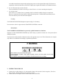
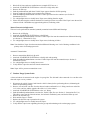
1
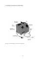
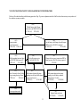
EELD105A USER MANUAL
LEAKCHECK SYSTEM
For Use By Qualified Automotive Technicians
LEAKCHECK MANUAL
P/N 200-8228
REV N/C 1999
NOTICE
Please note that the matters set out in this operating manual are intended only to provide information to
the user. This manual is not an exhaustive discussion, and does not constitute professional advice on the
matters in question. Please consult the manufacturer for further details and specific instructions or advice.
Although this operating manual has been prepared with the greatest care and attention to detail, the
manufacturer shall not be liable for damages or losses incurred due to any errors or omissions in this
operating manual.
1
TABLE OF CONTENTS
PAGE
1. PRODUCT OVERVIEW
A. Driveability Concerns
B. Present Detection Methods
C. Safety
D. Disclaimer
3
3
3
4
4
2. INSTRUCTIONS FOR USE
5
3. TEST METHODS
A. Air/Vacuum Leaks
B. Oil Leaks
C. Canister Purge System Leaks
D. Visual Engine Performance stability Test
E. Exhaust System/EGR Test
F. Under Dash Leak Test
G. Cooling System Leak Test
H. Brake Booster Test
5
5
6
6
7
7
8
8
8
4. TROUBLE SHOOTING
9
5. WARRANTY
9
6. LEAKCHECK COMPONENTS
10
7. FLOWCHART DIAGNOSIS FOR OPERATORS
11
8. TOXICOLOGY REPORT
13
9. AUTHORIZED SERVICE CENTER
13
10. FREQUENTLY ASKED QUESTIONS
14
11. PARTS LIST
15
2
1. PRODUCT OVERVIEW
Traditionally, in the automotive industry, engine oil leaks, transmission fluid leaks, manifold vacuum leaks, and
front and rear axle leaks have been detected using dyes with special lights and sound devices, even flammable
sprays. Technicians have spent countless hours detecting and locating leaks using these methods, with less than
desirable results.
In some industries, leak diagnosis has involved the use of Visible Vapor. This technology is effective but
expensive. The LEAKCHECK utilizes an affordable technology that uses Visible Vapor at specific pressure. It is
now cost effective for the professional automotive technician to use this reliable and efficient visual leak detection
technology.
Another key advantage to the LEAKCHECK visual diagnostic tool is that tests are performed with the engine
“off”. Automotive technicians are aware that while the vehicle’s engine is running, the computer is in control of
the engine, masking the Driveability problem. By testing with the engine off, the computer is taken out of the loop.
Therefore, with the LEAKCHECK, the computer is not compensating for, and hiding potential problems. Leaks
that previously went undetected are found literally in seconds.
LEAKCHECK SYSTEMS are engineered and manufactured to exceed accepted quality standards ensuring long
lasting durability for years to come.
A. Driveability Concerns
Driveability problems are difficult to detect. Reasons for this are include:
a. air evacuation leaks which are not visible to the naked eye;
b. modern, fuel-injected engines are controlled by a computer that will compensate for leaks and establish a
virtually correct idle speed that causes hesitation and defies electronic diagnosis;
c. The computer in a modern engine does not compensate for unfiltered air that is leaking into the intake without
passing through the mass air flow sensor;
d. Vehicles with carburetors will idle poorly because of an excessively lean mixture due to vacuum leaks;
e. Leaking vacuum hoses raise manifold pressure causing the emissions devices to malfunction, thus giving the
MAP sensor and fuel pressure regulator false readings, (this leaves the transaxle modulator, PVC system,
brake booster, and other vacuum powered items with insufficient vacuum to function properly).
The LEAKCHECK SYSTEM is the visual solution for identifying these difficult to detect problems.
B. Present Detection Methods
Automotive system leaks are detected through the time consuming process of elimination
Present detection methods include:
a. Manual inspection of the condition of all vacuum hoses:
Vacuum leaks may make a hissing noise when the engine is running. The noise may be altered by
manipulating the hose with the leak. This does not account for computer compensation, and is not a reliable
method;
b. Inspection of the engine’s mechanical condition:
A stethoscope may be used to inspect the engine’s mechanical condition. The sound drum and probe are
removed, then the stethoscope is inserted into the open end of the hose to detect the leak. False noises
occurring while the engine is running make it difficult to detect vacuum leaks.
c. Inspection of vacuum and air induction system connections:
3
Accessible connections are inspected by spraying soapy water over the suspected leak origin. The intent is to
temporarily seal the leak and cause an increase in engine speed. Again, this method is not considered accurate.
d. Use of a fluorescent dye to locate oil leaks:
This test method may be effective for this type of leak. However, it is time consuming and expensive.
e. Use of sonic testers:
Sonic testers were considered to be a potentially effective method for audibly testing for vacuum leaks.
However, extraneous noises may interfere with the detection process. Vacuum leaks located directly across
from each other may also cause inaccurate diagnosis.
C. Safety
The LEAKCHECK SYSTEM is designed to operate using a 12 volt battery.
Do not start the vehicle’s engine when the LEAKCHECK SYSTEM is connected.
D. Disclaimer
The LEAKCHECK SYSTEM must be operated by qualified automotive technicians.
Improper use of the LEAKCHECK SYSTEM may result in injury to yourself or someone else. It may also result in
damage to property.
The instructions in this manual are illustrations of how the apparatus may be used. These illustrations are examples
only and are not a substitute for training by a qualified representative.
/!\ WARNING
Some batteries may produce flammable gases.
Provide adequate ventilation. Keep lighted cigarettes, flames, and other ignition sources away
from the battery.
Do not start the vehicle with the LEAKCHECK SYSTEM attached to the car battery.
2. INSTRUCTION FOR USE
A. Connect the two cable clamps to a 12 volt automotive battery (red to positive, black to negative). The Green
light will glow, indicating that the battery polarity is correct.
B. Connect the hose to the quick connect on the LEAKCHECK SYSTEM.
4
C. Push the handheld pendant control button to produce Vapor.
D. Use a bright light source to locate Visible Vapor.
3. TEST METHODS
All tests are performed with the engine turned off. Battery clamps from the LEAKCHECK SYSTEM must be
attached to a 12 volt battery.
A. Air / Vacuum Leaks
This test encompasses intake manifold, unfiltered air, unmetered air leaks:
1. Attach the LEAKCHECK SYSTEM hose to any large intake manifold vacuum hose (i.e. brake booster of PVC
line).
2. Push the handheld pendant button to produce the Visible Vapor, (see Section 2. – Instructions For Use).
3. Use a bright light source to visibly locate the Vapor.
4. Leaking EGR valves can be detected during this procedure. Note that positive pressure EGR valves will leak.
Be sure not to condemn the EGR valve before checking to see if it is a positive or negative pressure EGR
valve.
5. Vapor sources indicating the need for a repair may be detected in the following areas:
Vapor Test Procedure
Throttle shafts/throttle body shafts
Throttle body gaskets
Injector O rings
Positive crank case vent hoses
Air valves
Exhaust gas recycle valves
Hoses and hose connection
Air cleaner assy.
Air cleaner duct hose assy.
Intake manifold gaskets
Vacuum advance modules
Charcoal canisters
Switches, one way valves
Choke pull off
Air flow meters/mass air flow sensors
MAP sensors
B. Oil Leaks
Carbureted Engine
X
X
X
X
X
X
X
X
X
X
X
X
X
PFI and TBI
Injected Engine
X
X
X
X
X
X
X
X
X
X
X
X
X
X
This test inspects the engine, transmission, and drive train components independently.
Engine:
5
1.
2.
3.
4.
5.
6.
Block off air from crankcase ventilation areas (example PCV hose etc.).
Attach the LEAKCHECK SYSTEM hose to the oil level (dip stick) tube.
Remove oil filler cap.
Push the pendant button until dense Visible Vapor appears from the oil filler opening.
Securely replace the oil filler cap to pressurize the crankcase.
Push the handheld pendant button to activate Visible vapor flow into the crankcase (see Section 2 –
Instructions For Use).
7. Use a bright light source to visually locate Vapor traces leaking from the engine.
8. Please note that an engine crankcase drained of oil could give better test results if the Vapor is not detected for
a known oil leak. Oil bubbles may appear during this test, indicating a leak.
Manual Transmission/Differential:
This test is to be performed on standard, (manual), transmissions and differential housings:
1. Remove the oil fill plug.
2. Attach the LEAKCHECK SYSTEM hose to the fill hole.
3. Push the handheld pendant button to activate Visible Vapor flow into the transmission or differential housing,
(see Section 2 – Instruction For Use).
4. Use a bright light source to visually locate Vapor traces, indicating oil leaks.
Note: You should see Vapor from the transmission/differential housing vent. Lack of housing ventilation is the
primary cause of oil leakage past seals.
Automatic Transmissions:
1. Remove transmission fluid level dip stick.
2. Attach the LEAKCHECK SYSTEM hose to the dip stick tube opening.
3. Push the handheld pendant button to activate Visible Vapor flow into the transmission (see Section 2 –
Instructions For use).
4. Use a bright light source to visually locate traces.
5. Verify that the Vapor does not leak from the transmission.
Note: Vapor will be present at transmission vents.
C. Canister Purge System Leaks
A charcoal canister is connected to the engine via a purge line. The fuel tank is also connected via a vent line to the
charcoals vapor recovery canister:
1. Disconnect the vehicle’s battery lead from the vehicle’s battery before performing this test, eliminating the
chance of spark during testing.
2. Remove one end of the vent line from the charcoal canister and install a “tee” fitting. Attach one end of the
“tee” to the vent line, and the opposite side of the “tee” to the canister.
3. Attach the LEAKCHECK SYSTEM hose to the “tee” fitting.
4. Push the handheld pendant button to activate the Visible Vapor flow (see Section 2 – Instructions For Use).
This allows you to test the charcoal canister, the fuel tank ventilation system, and the fuel filler cap seal.
5. Remove the fuel filler cap.
6. Wait until the Vapor is Visible.
7. Replace the fuel filler cap to pressurize the system.
8. Use a bright light source to visually locate the Vapor.
9. Verify that the Vapor is not originating from the gas cap and continuing to the canister purge system.
6
/!\ WARNING
During the test, the technician is pressurizing the fuel tank vent/fill system. Any leakage
will be accompanied by gas fumes. This test should be performed in a well ventilated area
that is void of any spark, ignition source, or heating device. Smoking is prohibited during
test.
D. Visual Engine Performance Stability Test
The LEAKCHECK SYSTEM may be used as a visual inspection tool prior to checking the condition of the
pistons, valves, and rings. It may also be used prior to a compression test or a cylinder down test:
1. Close both valves in the cylinder by bumping the engine or manually rotating the crankshaft or camshaft.
2. Remove the spark plugs and place the grommet supplied with your kit onto the tip of the LEAKCHECK
SYSTEM hose.
3. Insert the LEAKCHECK SYSTEM hose into the cylinder to be inspected.
4. Push the handheld pendant button to initiate Visual Vapor (see Section 2 – Instructions For Use).
5. Observe the Vapor:
a. If there is a leak in the intake valve you will see Vapor originating from the intake manifold, throttle body,
or carburetor.
b. If the head gasket is leaking you will see Vapor in an adjoining cylinder (look at spark plug opening).
c. If the piston or ring is leaking, Vapor will appear in the valve cover oil fill hole.
d. If the exhaust valve is leaking, vapor will appear at the tailpipe.
E. Exhaust System / EGR Test
The EGR system may be back tested for operation and flow by attaching the exhaust plug to the end of the exhaust
system.
1. Push the handheld pendant button to initiate Visible vapor (see Section 2 – Instructions For Use).
2. Fill the system with the Vapor.
3. Observe the exit points of the vapor. Please note that a small amount of Vapor will exit from the intake area
during this operation.
Note: If a large amount of Vapor is found to be leaking from the intake throttle area, an incorrectly seated EGR
pintle may be the cause. This test is valid for both positive and negative pressure EGR valves.
F. Under Dash Leak Test
1. Attach the LEAKCHECK SYSTEM hose to the vacuum supply line which is located near the fire wall under
the hood.
2. Push the handheld pendant button to activate Visible Vapor (see Section 2 – Instructions For Use).
3. Use a bright Light source to visually locate Vapor under the dash.
4. Check for Vapor leaks when operating the vacuum motors.
7
G. Cooling System Leak Test
This test detects hose leaks, leaks in the pump connections, leaks in the water pump seal, gasket installation leaks,
and coolant leaks into the combustion chamber. This test requires the purchase of an exhaust cone.
Note: This test will only be effective if there is no coolant present in the system:
1.
2.
3.
4.
5.
6.
7.
Drain coolant from the radiator
Insert the exhaust cone into the cooling system fill point.
Push the handheld pendant button to activate the Visible Vapor (see Section 2 – Instruction For Use).
Fill the system with Vapor.
Remove the exhaust cone.
Utilize conventional cooling system pressure testing to pressure the system to radiator cap rated pressure.
Use a bright light to visually locate Vapor traces indicating leaks.
Water Pump Installation Test (ensures accurate pump installation before complete assembly):
1.
2.
3.
4.
5.
Secure the water pump to the engine.
Insert the exhaust cone into one opening of the water pump while blocking off the other.
Push the handheld pendant button to activate the Visible Vapor (see Section 2 – Instructions For Use).
Fill the system with Vapor.
Use a bright light to visually locate Vapor traces indicating leaks.
H. Brake Booster Test
1.
2.
3.
4.
5.
6.
Remove one way check valve.
Insert the LEAKCHECK SYSTEM hose into the booster.
Push the handheld pendant button to activate the Visible Vapor (see Section 2 – Instructions For Use).
Fill the system with Vapor.
Slowly depress the brake pedal several times.
Use a bright light source to visually locate Vapor traces indicating vacuum leaks at the rear of the booster or
under the dash past the brake pedal to the master cylinder rod.
4. TROUBLE SHOOTING
If the LEAHCHECK SYSTEM fails to operate, do the following:
Check the battery
Ensure that the battery you are using is fully charged. If the battery is not fully charged it may cause slow
operation of the compressor and lack of Vapor.
Check the Connection
The LEAKCHECK SYSTEM operates on 12 volt DC power only. Ensure that the (2) connector clamps are
attached correctly and securely to positive (red) and negative (black) terminals respectively.
Check the temperature
If the LEAKCHECK SYSTEM operates best at room temperature. If it is cold, Vapor may not be produced; wait
until the machine reaches room temperature.
See Flowchart Diagnostics on Page 11 for trouble shooting guide.
8
5. WARRANTY
Limited Warranty
The manufacturer is not liable for any loss or damage whatsoever to person or property, however caused, including
consequential loss except to the extent of the Limited Warranty. The manufacturer does not warrant the
merchantability of the equipment or its fitness for any other purpose. In lieu of all other warranties whatsoever, the
manufacturer hereby limits its liability to the following:
Limited Warranty – The manufacturer shall, at its option, repair or replace the equipment or parts of it due
to defective material or workmanship within ONE YEAR from the date of purchase, upon proof of
purchase and delivery of the equipment to the manufacturer.
This warranty is null and void for damage caused due to accidents, tampering, misuse, corrosion, or failure
to follow operating instructions. (See Warranty Card for specific information).
9
7. LEAKCHECK SYSTEM AND COMPONENTS
(See Page 15 For Detailed Parts List Of External Components)
10
7.0 FLOWCHART DIAGNOSTICS FOR LEAKCHECK SYSTEM OPERATORS
Below is a flowchart describing troubleshooting procedures. Page 12 gives an explanation in detail of the flowchart, observations you may make, and
the conditions you may encounter.
(AA)
With the battery cable Clamps
connected is the GREEN LED on?
IF YES (A1)
IF NO (B1)
(A1)
Depress pendant,
does the pump run?
IF YES (A2) IF NO (A2)
(B1)
Are the battery cable clamps clean & clamped
RED to positive, BLACK to negative?
IF YES (A1)
IF NO (B3)
(A2)
With the pendant depressed, does
the RED LED flash on and off?
IF YES (A3)
IF NO (B2)
(B2)
Unit will require service
Call 1-800-225-5786
(B3)
Change cables to correct connection, RED to
battery positive, BLACK to battery negative?
YES (B4)
(A3)
After 60 seconds is there Visible
Vapor coming from tip of hose?
IF YES (A4
IF NO (B5
(b5)
With pendant depressed & pump
Running, does the pitch of the pump
Increase and decrease?
IF YES (A2)
IF NO (B2)
(B4)
With pendant depressed and pump
running, does the battery maintain
Voltage above 10 volts?
IF YES (B5)
IF NO (B6)
(A4)
System operation normal
(b6)
Replace battery and retest
IF YES (B5)
IF NO (B2)
11
CELL
AA
A1
A2
A3
B1
B2
B3
B4
CONDITION
OBSERVATION
Green LED ON
Green LED OFF
Pendant depressed
(with Green light
on)
Red LED Pulsing
(with Green light
on)
Red LED OFF
(with Green Light
on)
Indicates proper polarity. Battery voltage is over 10 volts
Battery cable clamps reversed. Battery voltage is below 10 volts/dead battery
Pulls in relay that powers the compressor and timer for Vapor Generator. Compressor
should run.
Red LED should flash on/off.
Indicates relay circuit, timer circuit, pendant, LED and load are ok.
Pendant
Depressed
Pendant running
Relay circuit OK
Pendant OK
Compressor OK
Timer module not operating.
No load from Vapor Generator
Defective Red LED
Pump NOT running
Battery voltage too LOW.
Pendant open circuit.
Relay circuit defective
Polly fuses open.
Compressor or wiring problems
Vapor visible
Compressor pressure/flow within range.
Relay, timing correct.
Vapor generator functioning.
Battery Conn.
System is polarity insensitive, however, for diagnostic purposes, it is preferred to be as
described.
Red clamp battery
Positive
Black clamp battery
Negative
Indicator LED’s are to aid in diagnostics ONLY
When Directed To This Screen You Should Have Completed All
Necessary Diagnostics And Be Ready To Answer Questions.
1-800-225-5786
Incorrect polarity on battery hookup cables as described in B1 so that
Diagnostic LED lights are visible.
Battery Condition
Using a volt meter, test to ensure battery voltage
Of over 10 volts DC is maintained during operation of the LEAKCHECK SYSTEM.
If a volt meter is not available, turn on the front headlights and observe the brightness.
When the LEAKCHECK SYSTEM is operated, if the head-lights dim dramatically,
charge or replace the battery before continuing testing.
B5
Pump Running
Red LED is pulsing. Is pitch of pump increasing and decreasing in volume (surging)?
B6
Replace Bad
Battery
If testing indicates bad battery, it must be replaced before further testing continues.
** If all conditions test OK and still no Vapor is produced, the unit will require canister replacement
by the three steps below.
1. Green LED
Red LED pulsating
2. Compressor running varying pitch (surging) sound from compressor.
3. But no Vapor coming from end of nozzle
12
8. TOXICOLOGY REPORT
Occutech Services (HSE) was contacted to undertake an Industrial Hygiene Survey of the LEAKCHECK
FOG (Visible Vapor) leak detecting machine at the University of Alberta Mechanical Engineering Lab.
Testing of the exposure of technician to vapor was performed during actual testing of the engine and a direct
sample of FOG was taken for comprehensive analysis. Ambient conditions were recorded immediately prior
to LEAKCHECK testing of the engine.
Personal sample results were less than ten percent of the lowest OEL, and components of the FOG would be
several one-hundredths of the appropriate OELs.
The conclusion reached from these tests is that occupational hygiene requirements will be met when the
LEAKCHECK equipment is used as designed and under normal conditions.
9. AUTHORIZED SERVICE CENTER
For further information on the LEAKCHECK SYSTEM, contact your SUN Representative.
13