Download Chapter 2 Spray Booth Description

Transcript
SPRAY BOOTH USER MANUAL
Contents
CHAPTER 1
1.1
GENERAL INTRODUCTION.................................................................................................................. - 1 -
GENERAL INTRODUCTION................................................................................................................................... - 1 -
CHAPTER 2
SPRAY BOOTH DESCRIPTION............................................................................................................. - 2 -
2.1 THE STRUCTION DESCRIPTION....................................................................................................................... - 2 2.1.1 THE MAIN ROOM...........................................................................................................................................- 3 2.1.2 GENERATOR PART.....................................................................................................................................- 6 2. 1.3 CONTROL PANEL......................................................................................................................................- 7 2. 1.4 SOME OPTIONAL PARTS........................................................................................................................... - 9 2.2 THE PRINCIPLE OF THE SPRAY BOOTH............................................................................................................. - 10 2.2. 1 SPRAY PAINTING PHASE.................................................................................................................................. - 10 2.2.2 DRYING PHASE............................................................................................................................................... - 11 2.3 TECHNICAL PARAMETER DIFFERENCE..............................................................................................................- 12 CHAPTER 3 THE INSTALLATION OF THE SPRAY BOOTH..........................................................................................- 13 3.1 THE INSTALLATION ENVIRONMENTAL CHARACTERISTICS............................................................................ - 13 3.2 SOME NECESSARY TOOLS............................................................................................................................ - 14 3.3 INSTALLATION METHODS AND STEPS........................................................................................................... - 15 3.3.1 Basement installation................................................................................................................................ - 15 3.3.2 Main room installation................................................................................................................................- 16 3.3.3 Ceiling Installation..................................................................................................................................... - 19 3.3.5 Generator Installation................................................................................................................................ - 23 3. 3.6 Control System Installation........................................................................................................................- 25 CHAPTER 4 TEST AND OPERATION......................................................................................................................... - 29 4.1 PREPARATION BEFORE................................................................................................................................. - 29 4.1.1 PREPARATION BEFORE TESTING AND OPERATION................................................................................ - 29 4.1.2 ATTENTION BEFORE TESTING AND OPERATION..................................................................................... - 29 4.1.3 TEST THE ROTATION OF THE BLOWER................................................................................................... - 29 4.1.4TEST THE DAMPER SYSTEM.................................................................................................................... - 29 4.2 ATTENTION NORMS....................................................................................................................................... - 29 4.3 OPERATION................................................................................................................................................ - 30 4.3.1 PAINTING STATION .................................................................................................................................. - 31 4.3.2 DRYING STATION .................................................................................................................................... - 31 4.3.3 MACHINE STOP...................................................................................................................................... - 32 I
SPRAY BOOTH USER MANUAL
CHAPTER 5
MAINTENANCE AND REPAIR............................................................................................................. - 33 -
5.1 ORDINARY MAINTENANCE.............................................................................................................................- 33 5.2 ORDINARY MAINTENANCE INSTRUCTION......................................................................................................- 33 5.3 SOME SPARE PARTS FOR MAINTENANCE..................................................................................................... - 34 CHAPTER 6
PACKING,SHIPPING AND STORAGE.................................................................................................. - 35 -
6.1 PACKING........................................................................................................................................................ - 35 6.2 SHIPPING.................................................................................................................................................... - 36 6.3 STORAGE.......................................................................................................................................................- 36 APPENDIX I : MALFUNCTION AND REMEDY.............................................................................................................- 37 APPENDIX Ⅱ : ELECTRICAL DRAWING(ATTACHED FILE)...................................................................................... - 38 APPENDIX Ⅲ : INSTALLATION DRAWING (ATTACHED FILE)...................................................................................- 38 -
II
SPRAY BOOTH USER MANUAL
Chapter 1 General Introduction
1.1 General Introduction
-
Read the manual carefully before proceeding to start the booth.
This manual has the aim of supplying the user all the necessary information so that,
besides a correct use of the booth, he is able to use it in the most auto and secure
possible way.
-
This manual is suitable for our different kinds of standard spraying/baking booth.Such as
EE-7501,EE-7503 and other similar nonstandard model. we sellect EE-7503
EE-7503as a sample to give
the instruction about the spraying/baking booth in this manual,also we will make some explaintion for
some special parts in the following chapter.
-
It is including the Technical aspect, Function, Machine stopper, Maintenance, Spare parts and Safety.
Before carrying out any operation on the Booth, the Operators and the Qualified Technicians have to
read the instructions contained in the present publication carefully.
If there is any doubt on the correct interpretation of the instructions, will consult our technical
department for the necessary explanations for you.
-
-
-
-
-
The manual is an integral part of the Booth, it has to be taken care of by the buyer, it
has to be positioned in the immediate vicinity of the Booth, inside a special container
and, above all, protected from liquids and anything that is liable to jeopardize its
legibility.
In the case of deterioration the construction firm will be happy to send another copy. in such a case it
is necessary to communicate to the technical office the characteristic data stamped on the special
identification nameplate. The manual has to stay with the machine in the event that it is sold..
The contents of the present manual conform to the directive 2006/42/EC and any consequent
modifications.Normanlly we make the spray booth with some electrical components without CE
certificate.And remark that if you need CE certificated make.
Data and drawings are only illustrative; the builder, having a pacific of constant development and
updating of the product, may make changes without any warming. It is forbidden for anyone to divulge,
modify or use this manual for personal reasons.
-1-
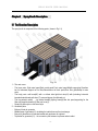
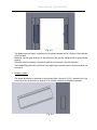
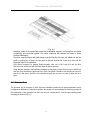
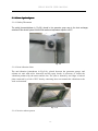
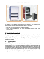
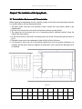
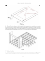
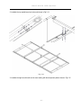
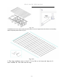
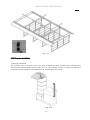
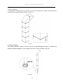
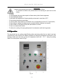
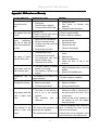
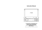
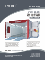
SPRAY BOOTH USER MANUAL
Chapter 2 Spray Booth Description
2.1 The Struction Description
The spray booth is composed of the following parts:( shown in Fig.2.1)
Fig. 2.1
1)The main room:
- The base parts: Side metal panel,Back metal panel,Front metal panel,Middle supporting,Strenthen
bar for basement,Support net for filter,Galvanization air block panel,Floor filter grids,Ramp for auto
enter.
- The body parts: wall board(20) with or without side light,front door(19) with (including horizontal
boardand stand board,safe door(17),surround pieces of wall board ect.
- The top parts(air cabint) : top sealed board(5),lighting frame(2),filter slot panel,supporting for the
filter,roof supporter beam(4,6),filter,roof cover(1).
- Ramp(18):grids style or vein board style.
2)Generator parts
- Bottom of heat-air generator
- Middle frame of generator(13) :including the intake fansr and heat exchanger
- Burner(14),diesel burn for standard model and gas burner for optional.
- Top-frame for generator(12)、the connection part between top frame and air cabint
-2-
SPRAY BOOTH USER MANUAL
- Damper(11) for change between painting and baking system.
- Exhaust system: exhaust fan with pre-filter(9),Active carbon environment system as option(11)
- Smoke tube(15):connect with heat-exchanger,take the heat out.
- Air duct(7):exhaust duct is necessary and intake duct as option.
3)Oil tank with frame.
4)Control system(16):control the motor,burner,light system ect.
2.1.1 The Main Room
The spray painting environment is the closed place when the spray painting and the drying process is
carried out. it is divided into the following parts:
1)Side walls
The side walls are necessary to isolate the spray painting environment from the outside,both from the
thermal and acoustic point of view, and above all so as not to disperse the paint and solvents residue into
the environment, it is formed by: (shown in Fig.2.2)
-
-
Fig 2.2
Side walls made of panels, with a thickness of 50 mm, modular types with tongue and groove
jointed,inserts with added seals. The thermic insulation of the spray painting environment is warranted
by the layer of expanded polyurethane or rock wool contained in the panels.
Back walls, panels made of the same type as the side walls.
Metal covers up the wall, are necessary for the up cover of the walls,which make each panel connect
together and easy to install the ceilling cover.
Back corners, that are necessary for the connection between the side walls and the back wall.
2)Front walls
The front wall of the booth is composed of : (shown in Fig.2.3)
-3-
SPRAY BOOTH USER MANUAL
-
Fig. 2.3
The header horrizontal panel, is necessary for the plenum chamber and as a closure of the head part
of the front wall.
Maid door with the glass windown, for the entry-exit of the operator, equipped with a spring release
opening.
Side erect panel,is necessary to support the maid door and connect to the side wall panel.
The installed fitting parts:such as the door lock,handle,hinges,connection bar for horrizontal panel and
erect panal.
3)Iumination system
-
The intemal illumination is warranted by the overhead lights ( shown in Fig.2.4 ) inserted into the top
of the side panels, positioned at an angle of 45°to warranty a sufficient and uniform illumination.
Fig. 2.4
-4-
SPRAY BOOTH USER MANUAL
-
-
The overhead lights are steel plates coated with paint ,in which four neon holders are positioned,
each of which fits four neons of 36 W, the neons are isolated from the spray painting environment by
panes of glass as the same type ot it used for the doors.
In order to reach the better illustration effect,we usually install the side light in the side wall, the neons
are isolated from the spray painting environment by panes
4) Ceiling
The ceiling acts as both a cover for the spray painting environment and supporting for the air filters at the
entrance, it is composed of: (shown in Fig.2.5)
-
Fig. 2.5
Top lights, including the neons of the illumination of the booth, they are the parts of the air cabin.
The filter frame, which are hanged with the top sealing panel.
Roofs, they are plates of zinced plate that are necessary for the cover of the booth.
The iron supporting beams, intercross by horrizontal beams and longitudinal beams,which are used
for supporting the ceiling.
Top sealing panel is installed on the supporting beams.And the top sealing pannel are necessary to
cover the ceiling and hold up the filter frame
5)basement
The basement serves as a plenum chamber which lead the exiting air from the booth. It is composed
of(shown in Fig.2.6)
-5-
SPRAY BOOTH USER MANUAL
-
-
-
Fig. 2.6
Basement, made of front panel,back panel,side panel,middle supportor and strengthen bar placed
longitudinally and connected together. The pieces composing the basement are made of zinced
pressure folded plates.
Floor filter supported frame and panel placed under the filter,the side rows and middle row with the
panel for keeping air off when all rows grids as optional. And the No 2 and No.4 rows with the
supported frame for air ventination.
Floor filter,is necessary for painting filtration.Usuallly cover row of No.2 and No.4 with the floor
filter.And cover all five rows with floor filter when all grids as optional.
Grids, that are inserted in the basement necessary for the flooring. There are five rows in total,Row 2
and Row Four should be the grids,and Row 1,Row 3 and Row 5 should be vein boards. but row No.2
and No.4 in the area in which the air is aspired the grids are only used, in order to allow the air to
pass.
2.1.2 Generator Part
The generator unit is necessary to start the forced ventilation needed for an optimal aerification and a
homogeneous distribution of the paint to produce the quantity of heat necessary for the drying process.All
the components of the generator unit are to be found in a closed booth . And the spray painting booth
consisting of (shown in Fig.2.7)
-6-
SPRAY BOOTH USER MANUAL
-
-
Fig. 2.7
Connector, for the connection between the generator unit booth and the spray painting
environment.Anti-vibration coupling in canvas is option so that the mechanical vibrations produced by
the motor are not transmitted to their booth.
Combustion room , equipped with a stainless steel heat changer and anti-exploding porthole as
optional.
Burner: Riello Diesel oil burner for standard.And the gas burner for option.
Centrifugal fan , action by an electric motor.
Enter filter frame, for pre-filtering incoming air.
Damper system, which is pneumatic drive.it is necessary to a partially recycle the air to be introduced
in the paintiing and drying process phase.
Air duct: take the exhaust out of the working area.
Chimney: take the exhaust heat out of the working area,is connect with flange.
Active carbon environmental system as option
2. 1.
1.33 Control panel
The control panel is composed of the following switches and indicators(Shown in Fig.2.8)
-7-
SPRAY BOOTH USER MANUAL
-
Fig. 2.8
Switch to block main doors
Drying process Timer(2), it is necessary in order to regulate the drying process.
Temperature meter(1), it is necessary to regulate the temperature of the air both for the spray painting
and drying process.
Burner indicator(3), it indicates the burner is opertation or not.
Burner Break down alarm(4), it alarms if there are something wrong about the burner.
Light switch(6),turn on or turn off the up and side light.
Emergence stop button (8),which can cut off the power when the emergence happen.
Selector switch of Painting and drying process(7), allows the passage from the spray painting phase
to the drying process and rise temperature painting.
Over load alarm(10), it alarms if the motor over-load or over-heat.
Start button(9), press it when you want to start the fans.
Power ON/OFF(11), turn the key when you want to start or close the power.
Power Indicator(13), it indicates the power is on or off.
Motor operation Indicator(12), it indicates the motor is on or off.
-8-
SPRAY BOOTH USER MANUAL
2. 1.
1.44 Some Optional parts
2.1.4.1 Safety Thermosta
The safety thermostat(shown in Fig.2.9), placed in the generator group near to the heat exchanger,
switches off the electric system if the air flow reaches a temperature superior to 90°C
Fig. 2.9
2.1.4.2 Anti-vibration Joint
The anti-vibration joint(shown in Fig.2.10), placed between the generator groups, and
exhaust air unit with active charcoals and the spray booth, is necessary to isolate the
vibrations produced by the motor and the fan. The joint is formed by two edges of zinced
plate connected by a belt of PVC that by contorting does not transmit the vibrations to the
work environment.
Fig. 2.10
2.1.4.3 Active carbon system
-9-
SPRAY BOOTH USER MANUAL
Fig. 2.11
The exhausting air unit with active charcoals shown in Fig.2.11,which the air from the spray painting
environment and to decrease the percentage of polluting agents. It is composed of:
-
Metal frame, there rock in the panel which can keep the temperature
Filtration group, composed of seven layer of active charcoal which remove the solvent fumes
(purification plant).
2.2 The principle of the spray booth
The spray booth is in a dustproof closed environment in which a flow of air of the capacity and
temperature necessary to make the booth function circulates. It works in two ways, one to carry out the
spray painting phase/flash period and one for the drying phase. The pressure inside the booth is kept
slightly greater than the atmospheric pressure (60mm H2O),so that it can prevent the dust get into the
booth during the operation.
2.2. 1 Spray Painting Phase
During the painting phase,both the intaker fan and exhaust fan are open,and the the damper shutter place
the position shown in Fig.2.12.The air capacity, aspirated from the outside by means of the generator fan
is precfiltered passing through the pocket filters, heated to the desired temperature (about 20°C), and
introduced into the plenum. Here an even distribution is obtained and a there is a second filtration through
the ceiling filter. After the filtration, the air crosses the booth from the top to the bottom part picking up the
paint pigments and the solvents left by the spray painting, it is then aspirated by the exhaust air unit
passing through the filters placed in the purification plant.(shown inf Fig.2.12)
- 10 -
SPRAY BOOTH USER MANUAL
Fig. 2.12
2.2.2 Drying Phase
During the dring phase,exhast fan will be turned off ,the intaker fan still operate,the damper change to the
posistion shown in Fig.2.13.At the same time the burner start to operate,and supper the heating for the
booth throught the heat-exchanger,and the enter into the internal cycle system.The ventination style is
similar the the painting phase,but the air throught the basement will be taken into the intake fan again and
form the internal cycly system. The temperature of the air has to be fixed according to the type of paint.
Usually the setted temperature should be 60°C
Fig. 2.13
- 11 -
SPRAY BOOTH USER MANUAL
2.3 Technical Parameter Difference
Sheet 2-1
Model
EE-7501
EE-7503
External Size(M)
7.0X5.3X3.5
7.0X5.3X3.5
Internal size(M)
6.9X3.9X2.7
6.9X3.9X2.7
Main Door size(M)
3X2.66 (WXH)
3X2.66 (WXH)
50mm(PE)
50mm(PE)
Fan capacity(M3/S)
24000
24000
Air velocity (m/s)
0.25-0.35
0.3-0.35
60℃-80℃
60℃-80℃
Power (KW)
9.5
16
Intake Fan(KW)
7.5
7.5
Exhausted Fan(KW)
--
5.5
Switch Damper
Pneumatic style
Pneumatic style
VCD adjust damper
No
No
Top Light Box
10×4×40W
10×4×40W
Side Light Box
No
8×2×40W
Ceiling frame
4 pcs
4 pcs
Two rows of grids,
Two rows of grids,
and three row of vein board
Ramp
2 pcs vein board style
Burner
Italy RIELLO G20
Italy RIELLO G20
Motor star method
Direct start connect
Pressure Meter
No
No
Auto Suitable
Saloon car
Saloon car
Remarks
Chinese Standard
Chinese Standard
Parameter
Filled material thickness
Drying Temperature
Floor
- 12 -
Direct start connect
SPRAY BOOTH USER MANUAL
Chapter 3 The Installation of the Spray Booth
3.1 The Installation Environmental Characteristics
Before beginning the assemblage work it is necessary to make sure that the environment where the booth
is to be kept conforms with the characteristics below:
1. The electric power circuit has to be measured in order to ensure the correct function based on the
installed power.
2. The face of the structure has to be smooth and leveled to warranty a perfect function
3. The support plan of the structure has to be of compacting material, sufficiently resistant to bear the
weight of the whole machine
4. For the correct function of the booth it is necessary that it has around it the minimum space as shown in
Fig.3.1.
5. The pipeline system has to be predisposed to allow the influx of fuel to the burner.
6. it is necessary to ensure the exit of the emission pipelines and of the air extraction furthermore it is
necessary that the ends of these two pipelines are positioned in such a way that the discharged air is
not aspirated.
Fig. 3.1
Model (mm)
A
B
C
D
E
F
G
H
I
J
EE-7501
7000
4000
2300
2950
1255
500
1100
2000
3500
500
EE-7503
7000
4000
2300
3150
1255
500
1100
2000
3500
500
- 13 -
SPRAY BOOTH USER MANUAL
3.2 Some Necessary Tools
We will not offer the installation tools for the user,so you should prepare some necessary tools as shown Fig.3.2
Fig.3.2
- 14 -
SPRAY BOOTH USER MANUAL
3.3 Installation Methods and Steps
3.3.1 Basement installation
The basement installed step shown as the following step(shown in Fig.3.3)
Fig. 3.3
1. Put the metal board(front,back,sides)and middle bracket in the right place,and connect them with bolt
M8*20 according to the demand of the installation chart.then screw down.Shown in Fig.3.4.
Fig. 3.4
- 15 -
SPRAY BOOTH USER MANUAL
2. Adjust the level of the connect point: find the highest point with the level measure apparatus,then
elevate other points with something.Shown in Fig.3.5
3. Adjust the uprightness: adust the side boards and middle bracket with beeline,and distribute the distant
between the rows,so that we can put the grids easily.Shown in Fig.3.5.
4. Check that all the longitudinal pieces have been mounted perfectly perpendicular to the end heads, to
do this measure the two diagonals between the corner of the anterior end head and the opposite corner of
the anterior end head, if they show the same values we are certain that it is assembled correctly. and the
error value should be less than 5mm (shown in Fig.3.5).
5. Installate the bottom of the heat-air generator: the air out mouth should be connect with the metal sides
board.(shown in Fig.3.5)
Fig. 3.5
3.3.
.3.22 Main room installation
1. Front door installation
Installate the front door frame(shown in Fig.3.6)
1) Put the left and right side panel (B01&B03)on the ground,connect the the horizontal panel(B02) with
the side panel.make sure that the gap should be smallest.
2) Measure the diagonal of the length and width,when they are suitable for the demand of the door
frame size (shown in Fig.3.6),L1=L2,fix the door frame with appoint connect board(B04).Pay attention to
that check the sizes of the door frame after fixing.
- 16 -
SPRAY BOOTH USER MANUAL
Fig. 3.6
3) Take the Front door frame on to the front panel of the basemenet by two workers,then one workers
hold the door frame and another worker take the safe door and one wall panel on aother side,connect
them to the door frame with nails . At last take four bolt M8*20 to connect the bottom of the door frame
and the front panel of the basement. shown in Fig.3.7. So the door frame can be stand steadily.
Fig. 3.7
2. Wall panel installation
1) connect the wall board in turn and fix the to the down U style slot with nail,make sure the gap should be
smallest.Check the whole length of two sides wall board should be suit for the demand.(shown in Fig3.8)
- 17 -
SPRAY BOOTH USER MANUAL
Fig. 3.8
2) Installate the edges inside and outside.(shown in Fig.3.9)
3) Installate the cover of the wall panel(shown in Fig.3.9)
4)Air enter connector installation
The air enter connector is necessay between the top frame of generator and air cabin.(shown in
Fig.3.9). Install the cover of the shorten panel,then connect to zinc panpel with nail and do
some sealing.
Fig. 3.25
- 18 -
SPRAY BOOTH USER MANUAL
4. Main door installation
Installate the door,including the lock,hinge,handle,plastic sealing bar and so on.(shown in Fig.3.10)
Fig. 3.10
5. Safety door installation
Safety door is necessary for pretecting the worker’s safety when they working inside the booth.When the pressure inside
the booth is over large,the pressure lock of safety door will be open automactic.Install it shown in Fig.3.11. The pressure
lock can be adjusted,not too tight and to loose is ok.
Fig. 3.11
3.3.
.3.33 Ceiling Installation
The ceiling shown in Fig.3.12
- 19 -
SPRAY BOOTH USER MANUAL
Fig. 3.12
1. Supporting beam installation(shown in Fig.3.13)
1) Installate the horizontal beam to the up rim of side wall panel with the bolt.
2) Installate the vertical beam to the front and back wall with nails.
3) Connect the horizontal and vertical beam together with the nails.
Fig. 3.13
- 20 -
SPRAY BOOTH USER MANUAL
2. Installate the top sealed board and cotton slot shown in Fig.3.14
Fig. 3.14
3. Installate the light box with nails and do some sealing with the transparent pastern shown in Fig.3.15
- 21 -
SPRAY BOOTH USER MANUAL
Fig. 3.15
4. Installate the roof cover ,connect one by one,then fix them on to the roof support beam with nails.And do some sealing
with the transparent pastern shown in Fig.3.16
Fig. 3.16
5. Filter frame installation shown in Fig.3.17. Fix the filter on the frame with frame slot fir
st,then installate the filter frame with the hinge.
- 22 -
SPRAY BOOTH USER MANUAL
Fig. 3.17
3.3.
.3.55 Generator Installation
1. Main part installation
The generator part is the main part of the spray booth,the sperative part had been installed before
delivery.Connect them together shown in Fig.3.18 is ok.. The generator is heavy, so please pay attention to
move them on to the basemen. Take with the Fox car would be better if you have.
Fig. 3.18
- 23 -
SPRAY BOOTH USER MANUAL
2. Duct installation.
Considering the shipping space,the duct have not been installated,user should assemble them by
yourself.The connection method shown in Fig3.19.
Fig.3.19
4. Chimney installation
The chimney should be connect to the fire outer of the heat-exchanger,and extent to outside.All the
chimney had been assembled . So you connect it one by one. That is ok.Shown in Fig.3.20
Fig. 3.20
- 24 -
SPRAY BOOTH USER MANUAL
3. 3.6 Control System Installation
1.Control damper installation
The damper is exchanger between painting and baking system.the installation and test shown in Fig.3.21.
Connect the air pile according to the following pictures,and the air compressor should be prepared by the user.The
pressure should be setted to 0.4~0.6Mpa as the pressure meter.Take the screw up and turn to adjust.
Fig.3.21
ATTENTION: There is a vane inside the damper shown in Fig.3.22.When the
vane in the position A,that is the painting system,and when the vane in the
position B,that is the baking system.You can test it when you operate it.If you find
the wrong position,change the air pipe Port C and Port D shown in Fig.3.23.That is ok.
Fig. 3.22
Fig.3.23
2. Burner installation
1)Install the burner to the connection mounth of the heat-exchanger,then fix it with bolts shown in Fig.3.24
- 25 -
SPRAY BOOTH USER MANUAL
Fig. 3.24
2)Connect the burner and oil tank with the oil pipe,and don’t forget to connet the oil cup.shown in Fig.3.25.
Fig. 3.25
3. Temperature testing system installtion
Installate the temperature explorer at the middle of the ceiling inside the booth,and the wire connect to G
port of the temperature meter directly through the ceiling air cabin shown in Fig.3.26
- 26 -
SPRAY BOOTH USER MANUAL
Fig. 3.26
4. Compressure meter testing system installtion
No loop for the pressure meter,just use one transparen air pipe insert one port of the meter,and another
port of the meter should be plug up.The other side of the air pipe should be put into the painting room
throught the ceiling air room. shown in Fig.3.27
Fig. 3.27
5. The control box installation and wire connecting
1)Install the control box into to wall panel near the generator shown in Fig.3.28,and install the installation
panel onto the wall with nail,then install the control box on to the panel.
Fig. 3.28
- 27 -
SPRAY BOOTH USER MANUAL
2) Wire connection
The main component have been connected before delivery,the connection to the control box. you should
do as follow in Fig.3.29:
Connect the power supply into the control box and conect the control box to the burner,motor,light and
control damper with electric wires according to the electrical chart we offer.
Fig. 3.29
Attention: You must connect the motor wire according to the electrical chart offered.And
you must be attention to the start method of the motor,Generally our spray booth have two
start methods: motor direct start connection and Y/△ start connection.When you
choose the direct start of motor ,The Up and Down ports of the motor should be
connected with the metal pad,and then connect three ports (Up or Down) to the
control box shown in fig.2.30.When choose Y/△ start connection,you must take
the metal pad out,and connect to the six connection ports in the motor.
Fig. 3.30
- 28 -
SPRAY BOOTH USER MANUAL
Chapter 4 Test and Operation
4.1 Preparation Before
4.1.1 Preparation before testing and operation
- Prepare three phase electric power supply which is suitable for the motor connection.
- Prepare the air compressor for the control damper.
- Check the control system connection of the damper,the testing method as the chpter 3 mention.
- Prepare enough diesel oil in the oil tank.
4.1.2 Attention before testing and operation
- Check the connection of the electric chart according to the chart we offer.Make
sure that you must ask someone who has the qualification of the electrical work.
- Check the connection of the diesel oil pile and the connector,the leakness
phnenomenon is forbidden.
- Keep to all the signaling of danger and safety posted on the booth.
- The qualification of the personnel, The personnel employed to work on the booth, before beginning
the work, has to have studied the "SAFETY " because during the work there will not be time. This is
important above all for the personnel who only work sporadically.
- During the painting process,it is forbidden for the personnel to go into the booth, with non-regulation
clothing ( including necklaces, bracelets, rings etc.).
4.1.3 Test the rotation of the blower
- Intake blower testing:Open the pre-filter cabin in the generator and check the rotation of the fan,make
sure the air can be taken in when the fan turn on.
- Exhaust blower testing:Take out the cover panel of the exhaust cabin,check the rotation of the
fan,make sure the air can be taken out when the fan turn on.
4.1.
.1.44Test the damper system
The main function of the damper is the transition between the painting system and baking system.the test
method shown in Chaper three.
4.2 Attention Norms
-
In the paragraphs below are listed all the regulations and prohibitions to be observed in
order to prevent possible accidents:
- Prepare and keep paints in a place outside of the spray painting environment.
- Clean the inside surfaces of the oven and the glass of the overhead lights from
possible paint residue or solvents.
Use the spray paint gun correctly: spray only in the direction of the surfaces to be to painted,in order
to keep the operator in clean air.
Make sure that inside the vehicle there are not dangerous objects or substances.
Make sure that the emergency exit is free of objects that may hinder the opening in emergency cases.
Make sure that all the discharge air and smoke ducts are protected by the appropriate grates and that
the air passage is not obstructed.
- 29 -
SPRAY BOOTH USER MANUAL
Inside the spray painting environment, it is FORBIDDEN as follows
- To introduce the vehicle to be painted without first removing the petrol tank and the
battery.
-
To smoke
To use equipment that can produce sparks or flames and any kind of electric apparatus.
To use incandescent objects.
To paint when the temperature of the spray painting environment is more than of 25℃.
To enter during the drying process phase.
To use more than 150 g of paint for 1000 Nm3/h of air ( corresponding to a max of 2. 7 Kg/h of paint)
To keep objects or dangerous substances such as aerosol bombs, containers and solvents,
To wear overalls or other garments dirty with paint residue or solvents.
To have or consume food or drinks
To climb on the roofing of the spray painting booth, the exhaust air runoff and the generator.
4.3 Operation
The spray booth has two working station:Painting station and drying station,the two station have been
connected each other and have the different operation.And during low temperature environment in the
winter,we should open the burner and rise the temperature about to20 ~ 25 ℃ during the painting
station.The control panel is shown if Fig.4.1
Fig. 4.1
- 30 -
SPRAY BOOTH USER MANUAL
4.3.1 Painting station
After having cleaned and prepared the vehicle, the operations functions for the painting phase
as following steps.
1.Turn on the key switch to open the power supper,and press the light switch to turn on the
lights
2. Drive the vehicle into be spray,and close the main door.
3. Check the setting value of temperature meter and dring timer,normally the value had been setted by the
manufacture.And the dring temperature should be 60 ℃ and the dring time should be about 30 ~
45minutes.
4.Check the shuff of the damper is in the right position
5. Press the motor button to open exhaust ,you can see the indictor of the motor turn on,and the intake
fan will start about 10 seconds later.
6.The worker get into the booth through the safety door and do the painting.If the temperature is low,turn
the dring/painting switch to left and open the burner and rise the paiting temperature(during the heating
painting system the burner will stop automatic when the temperature rise to 25 ℃ ,and when the
temperature go down to about 20℃,the burner will start again).
7.The worker get out from the booth throuth the safety door when finish the painting.Then change to
baking station.
4.3.2 Drying station
The operations to follow in the drying process phase are:
1. Make sure that all the spray painting functions are ended and that the operator has gone out of the
spray painting environment.
2. Check there is enough diesel oil in the oil tank and no leaking of the oil pipe.
3. Check the setting value of temperature meter and dring timer,normally the value had been setted by the
manufacture.And the dring temperature should be 60 ℃ and the dring time should be about 30 ~
45minutes.
4.Turn the dring/painting switch to right to open the burner.At the same time the damper will turn to
another position and the light will turn off automatic.And the exhaust fan will turn off,but the intake fan is
keeping operation.
5.The spray booth will be working automatic till the setting dring time finished.
6.When the setting dring time is finished,the burner will stop automatic first,then the motor will stop about
5 minutes later.
7.The light will be turn on again after the motor stopping.
Attention: Don’t do any setting for the temperature meter.We have resetted all the data for
the program.The setting you can do is only setting the drying temperature(Default data is
60℃) and the drying time(Default data is 30minutes)
- 31 -
SPRAY BOOTH USER MANUAL
4.3.3 Machine Stop
To stop the booth before the foreseen time it is necessary to:
1. Turn the burner switch onto the OFF position(Middle position).
2. Open the gate of the booth and let the vehicle out.
3. Switch off the lights if they are on
4. Turn the general switch onto the OFF position.
5. Wait for about 15 minutes in order to get the air condition inside the booth,then close the main doors.
ATTENTION: After drying,if there is more heating or exhaust air inside the booth,it is
necessary to start again from the spray painting cycle in order to allow the reinstatement of
the initial condition with an adequate ventilation.
- 32 -
SPRAY BOOTH USER MANUAL
Chapter 5 Maintenance and Repair
5.1 Ordinary Maintenance
Maintenance has to be a preventive and planned activity, seen as fundamental need to obtain safety, as a
presupposition that the machines and the apparatus are subject to wear which is apotential cause of
breakdowns.Therefore the safety of the booth depends also on a good preventive maintenance that
aflows the substitution of the objects subject to wear out before the verification of the technical faults.
Please carrying out the maintenance intervention /cleaning as the following ordinanry
maintenance and frequency verification instructions:
-
-
Keep the booth clean and keep the intake and exhaust duct be open.
Change the top filter after painting 200sets of auto or use more than one year,But in the more dust
situation,that should be shorten the filter changed period according to the actual condition.
Change the Pre-filter after painting 200sets of auto or use more than one year.
Change the flour filter after painting 200sets of auto or use more than one year.
Clean the filter oil cup and fire nozzle of the burner each week,keep the oil route be through.
Add the diesel oil is forbidden when the burner is working.
Make sure there are more than 5L oil in the oil tank,use Non diesel oil is forbidden.
Check the filter net of the activatied charcaod environmental cabinet after painting 20sets of auto or
use more then 1 mouth.If the painting adhibit to the filter net fulled,change the filter net in time and
keep the ventination be through.
Check the heat exchanger every two months,examine whether have the bad welded
phenomena,make sure saftey enough.
Clean the dust adhered to the fans and blades semiyearly
When you don’t operate the booth for a long periods,cut off the general power,and open the door for
ventination every three days,in case accumulate the moisture air inside the booth.
Change the heat exchanger and all of the electric wire when using more than 8 years.
Maintenance in time is necessary,but the appropriate maintenance is also very
important,you should abide to the following mainly maintenance method and attention
problem
5.2 Ordinary Maintenance Instruction
The procedures of ordinary maintenance as a rule are done by qualified and authorized
personal and however, before beginmng the maintenance, the following functions have to
be done.
-- Remove the motorvehicle from the spray painting environment.
- 33 -
SPRAY BOOTH USER MANUAL
-- Turn the main switch to be off..
-- Disconnect the control panel switching off by means of the switch place on top..
-- Close the general switch with the padlock and keep the key during the phases of maintenance.
ATTENT
ATTENTIION: All the used filters (pocket filters, ceiling filters, basement filters, synthetic
filters and bunker activates ) cannot be disposed of as normal urbanwaste, neither can
they be burnt, but they must be given to the appropnate authority for disposal.
5.3 Some Spare Parts for Maintenance
-- Ballast for the light tube.
-- Fuse for control box.
-- Light tube for lighting
-- Filter for dust prevent
- 34 -
SPRAY BOOTH USER MANUAL
Chapter 6 Packing,shipping and Storage
6.1 Packing
The spray booth is generally delivered in various sub components palletized and in different packaging.
The handling of the packages has to be done using the correct means of capacity transport for the weight
to be lifted.
In some cases the components are systematized loose in the loading bay ( container, truck, etc. )
in such cases it is necessary to unload and move the various individual parts and in such a way as to
warranty the maximum safety for working personnel.Some package shown as the following picture.
Fig.6.1
- 35 -
SPRAY BOOTH USER MANUAL
6.2 Shipping
During the handling operation it is forbidden for third persons to go near the lifted load.
- The points indicated with the arrows are those to used for lifting.
- In case a crane is used verify that the capacity of the hemp bands is enough for the weight to
be lift.
If the generator unit and exhaust air unit with active charcoal are supplied already assembled they are to
be moved with a dolly elevator of sufficient capacity ( see figure ) forking the unit as indicated.
Fig.6.2
6.3 Storage
Under the case of storage of the booth before unpacking, it is necessary to put it in a place protected from
bad weather, that is fresh and dry.
After having transported the booth package to the place destined for the installation, remove the wrapping
and verify that:
a. The content of the package corresponds to what was agreed upon in the order.
b. That there are not visibly damaged parts.
In both cases, in case problems are encountered, do not proceed with the assemblage of the
booth and warm the builder immediately of the damage and/or of the missing parts ascertained. on the
opening the wrapping.
The residue material of the packing is disposed of in accordance with the actual
normative in force with respects to waste disposal
- 36 -
SPRAY BOOTH USER MANUAL
Appendix I : Malfunction and Remedy
MALFUNCTIONING
PROBABLE CAUSE
The moter can not
Start
1. Fusing fault
2. Thermal relay in operation
3. The motor,wires circuit break
REMEDY
1. Change new fuse
2. Push button of thermal
reposition
3. Change the moter and wires
relay
1.Pre-filter Jam
The Capacity of the fan
1.Clean or change the filter
2.Damper have been right open or
is small
2.Open the damper completely
not open enough position
1. Use out of oil in the reservior
Burner
malfunction
2. Oil pipe connector leakage
light turn on after the
3. Too dirty in the filter net of the
burner have started 20
oil intake pipe
seconds
4. Electrical ege is too dirty
1.
2.
3.
4.
Add some diesel
Reconnect the pipe
Clean the fliter net
Clean the eletrical ege
1. Check and clean the pump of the
1. The pump strip is lock
burner
2. The setted time have finish
The pump of burner
2. Reset the time
3. The temperature valve have
does not start to work
3. Reset the temperature
reach the setted valve
4. Check the level of fuel in the
4. The burner is out of fuel
reservior
1. The open position of burner
1. Adjust the damper more to more big
Black smoke come out
damper is not enough
position
after the burner open
2. The pressure of pump is not
2. Reset to the standard valve
enough
Temperature rise is 1.The damper is not close or not
1.Closed the damper completely
slow
closed completely
1. The fuses have blown
1. Replace the light fuses
The lights do not work 2. Ballast is interrupted
2. Replace the ballast
3. Connection ports loose
3. Fix the connection ports
1. CheckThe exhaust air unit fuses
1. The motor of the exhaust ir
Ensure the cable is connectyed to
The pressure inside the
unit is off or not working
the motor and the the locks of the
booth is higher than
regularly.
control panel
usual
2. The extraction duct is 2. Check the filter of the basement or
obstructed
the exhaust air unit and replace
them if necessary.
1.Check the generator fuses. Ensure the
The pressure in the 1.The motor of the generator is off cable is connected the motor and the
booth is lower than or does not work regularly
locks of the control panel.
usual
2.The emission duct is obstructed 2.Check there are not obstacles at the
mouth of emission of the intake air unit.
- 37 -
SPRAY BOOTH USER MANUAL
Appendix Ⅱ : Electrical Drawing(Attached File)
Appendix Ⅲ : Installation Drawing (Attached File)
- 38 -