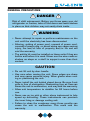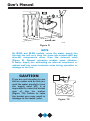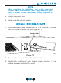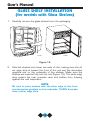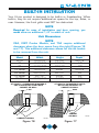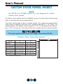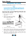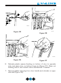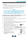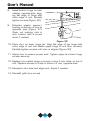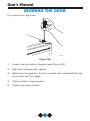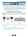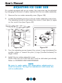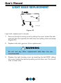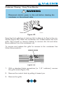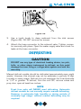
1
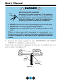
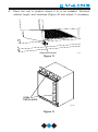
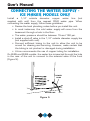
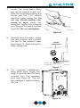
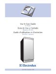
8/4/04
1:37 PM
Page 1
P.O. Box 245040
Milwaukee, WI 53224-9540
Phone 414.354.0300
FAX 414.354.7905
www.U-Line.com
Printed in U.S.A.
P/N 30035
R
R
R
User’s Manual
Bev Center Cover
ICE-MAKERS,
COMBOS,
REFRIGERATORS,
75 BEV BEVERAGE
CENTER
Bev Center Cover
8/4/04
1:37 PM
Page 2
U-LINE CORPORATION LIMITED WARRANTY
U-Line Corporation warrants each U-Line product to be free from defects in materials and
workmanship for a period of one year from the date of purchase; and warrants the sealed
system (consisting of the compressor, the condenser, the evaporator, the hot gas bypass
valve, the dryer and the connecting tubing) in each U-Line product to be free from defects
in materials and workmanship for a period of five years from the date of purchase. During
the initial one-year warranty period for all U-Line products U-Line shall: (1) at U-Line’s
option, repair any product or replace any part of a product that breaches this warranty; and
(2) for all Marine, RV and Domestic U-Line products sold and serviced in the United States
(including Alaska and Hawaii)and Canada, U-Line shall cover the labor costs incurred in
connection with the replacement of any defective part. During years two through five of the
warranty period for the sealed system, U-Line shall:. (1) repair or replace any part of the
sealed system that breaches this warranty; and (2) for all Marine, RV and Domestic U-Line
products sold and serviced in the United States (including Alaska and Hawaii)and Canada,
U-Line shall cover the labor costs incurred in connection with the replacement of any defective part of the sealed system. All other charges, including transportation charges for
replacements under this warranty and labor costs not specifically covered by this warranty, shall be borne by you. This warranty is extended only to the original purchaser of the
U-Line product. The Registration Card included with the product should be promptly
completed by you and mailed back to U-Line or you can register on-line at
www.U-LineService.com.
The following are excluded from this limited warranty: installation charges; damages
caused by disasters or acts of God, such as fire, floods, wind and lightening; damages
incurred or resulting from shipping, improper installation, unauthorized modification, or misuse/abuse of the product; customer education calls; food loss/spoilage; door and water
level adjustments (except during the first 90 days from the date of purchase); defrosting the
product; adjusting the controls; door reversal; or cleaning the condenser.
If a product defect is discovered during the applicable warranty period, you must promptly
notify either the dealer from whom you purchased the product or U-Line at P.O. Box 23220,
Milwaukee, Wisconsin 53223 or at 414-354-0300. In no event shall such notification be
received later than 30 days after the expiration of the applicable warranty period. U-Line
may require that defective parts be returned, at your expense, to U-Line’s factory in
Milwaukee, Wisconsin, for inspection. Any action by you for breach of warranty must be
commenced within one year after the expiration of the applicable warranty period.
This limited warranty is in lieu of any other warranty, express or implied, including,
but not limited to any implied warranty of merchantability or fitness for a particular
purpose; provided however, that to the extent required by law, implied warranties are
included but do not extend beyond the duration of the express warranty first set
forth above. U-Line’s sole liability and your exclusive remedy under this warranty is
set forth in the initial paragraph above. U-Line shall have no liability whatsoever for
any incidental, consequential or special damages arising from the sale, use or installation of the product or from any other cause whatsoever, whether based on warranty (express or implied) or otherwise based on contract, tort or any other theory
of liability.
Some states do not allow limitations on how long an implied warranty lasts or the exclusion
or limitation of incidental or consequential damages, so the above limitations may not apply
to you. This warranty gives you specific legal rights, and you may also have other rights
which vary from state to state.
INTRODUCTION
Congratulations on your purchase of your U-Line product. A pioneer in
the field for more than 40 years, U-Line is the world’s number one manufacturer of built-in, under-counter ice making and specialty refrigeration products. U-Line dedicates 100% of its research and development
to these products. The result: U-Line technology leads the market with
innovation, design, depth of product line and performance.
U-Line also backs customers with a strong dealer network.
U-Line’s commitment to quality even extends to environmentally safe
packaging. U-Line products are making life more convenient in homes,
businesses, and hotels around the world.
PLEASE READ all instructions completely before attempting
to install or operate the unit. All models of Ice Makers and
Combos require a connection to the water supply and
improper hook-up can result in substantial property damage! If you are unsure of your ability to safely connect the
water supply to the unit, consult a licensed plumber for
assistance.
Once you have your unit installed, we suggest you keep this manual in a
safe place for future reference. Should any problems occur, refer to the
TROUBLESHOOTING section of this manual. This information will help you
quickly identify a problem and get it remedied. In the event you require
assistance, please contact the dealer where you purchased your unit.
1
User’s Manual
PLEASE RECORD YOUR MODEL’S INFORMATION
Whenever you call to request information or service, you will need to
know your model number and serial number. You can find this information on the serial plate located on the inside wall of your unit and on
the product registration card.
PRODUCT REGISTRATION CARD
The package containing this manual also includes your product registration information. Warranty coverage begins at the time your unit
was purchased.
NOTE
Complete and mail the Product Registration Card as soon
as possible to validate the registration date. You may also
register the product online at www.U-LineService.com.
If you do not return your Product Registration Card, U-Line will use the
date of sale to the U-Line distributor as the first date of
warranty for your unit. Please also record the purchase date of your
U-Line unit and your dealer’s name, address and telephone number.
Model Number:
______________________________________
Serial Number:
______________________________________
Purchase Date:
______________________________________
Dealer Name:
______________________________________
Dealer Address:
______________________________________
Dealer Telephone: ______________________________________
Keep this manual and the sales receipt together in a safe place for further
reference.
2
TABLE OF CONTENTS
INTRODUCTION..........................................................................1
SAFETY PRECAUTIONS ...............................................................4
INSTALLATION ...........................................................................7
LEVELING THE UNIT .................................................................10
CONNECTING THE WATER SUPPLY – ICE MAKER MODELS ONLY ..12
GRILLE INSTALLATION ..............................................................15
GLASS SHELF INSTALLATION.....................................................18
BUILT-IN INSTALLATION.............................................................19
CUSTOM DOOR PANEL INSERT..................................................20
WINE RACK REMOVAL/INSTALLATION.......................................25
REVERSING THE DOOR .............................................................26
REVERSING A STAINLESS STEEL DOOR.......................................31
ALIGNING THE DOOR................................................................32
WINE RACKS – 75 BEV ............................................................33
INITIAL START-UP AND ADJUSTING THE
TEMPERATURE CONTROL.......................................................34
TEMPERATURE CONTROL .........................................................35
NORMAL OPERATION ...............................................................37
MARINE USE ...........................................................................39
ADJUSTING ICE CUBE SIZE .......................................................40
LIGHT SWITCH AND BULB........................................................41
LIGHT BULB REPLACEMENT .....................................................42
PROPER STORAGE AND STOCKING RECOMMENDATIONS .............43
THE RIGHT TEMPERATURE FOR WINE........................................43
CLEANING & MAINTENANCE.....................................................44
DEFROSTING ...........................................................................47
STORAGE ................................................................................48
TROUBLESHOOTING .................................................................49
IF SERVICE IS REQUIRED ...........................................................51
REPLACEMENT PARTS .............................................................51
SPECIFICATIONS.......................................................................52
3
User’s Manual
SAFETY PRECAUTIONS
Do not attempt to install or operate your unit until you have read the
safety precautions in this manual. Safety items throughout this manual
are labeled with a Danger, Warning or Caution based on the risk type.
DEFINITIONS
!
This is the safety alert symbol. It is used to alert you to
potential personal injury hazards. Obey all safety messages
that follow this symbol to avoid possible injury or death.
! DANGER !
DANGER indicates an imminently hazardous situation
which, if not avoided, will result in death or serious injury.
! WARNING
WARNING indicates a potentially hazardous situation
which, if not avoided, could result in death or serious injury.
! CAUTION
CAUTION indicates a potentially hazardous situation which,
if not avoided, may result in minor or moderate injury.
CAUTION
CAUTION used without the safety alert symbol indicates a
potentially hazardous situation which, if not avoided, may
result in property damage.
Indicates installation, operation or mainenance information
which is important but not hazard related.
4
GENERAL PRECAUTIONS
! DANGER !
Risk of child entrapment. Before you throw away your old
refrigerator or freezer, take off the doors and leave shelves
in place so that children may not easily climb inside.
! WARNING
• Never attempt to repair or perform maintenance on the
unit until the electricity has been disconnected.
• Altering, cutting of power cord, removal of power cord,
removal of power plug, or direct wiring can cause serious
injury, fire and/or loss of property and/or life and will
void the warranty.
• The anti-tip kit must be installed on these units if they are
built-in and before it is used. Never use the wine racks or
shelves as steps or a shelf to support more than their
content.
CAUTION
• Do not lift unit by door handle.
• Use care when moving the unit. Some edges are sharp
and may cause personal injury. Wear gloves when moving or positioning the unit.
• Never install the unit behind closed doors. Be sure front
grille is free of obstruction. Obstructing free air flow can
cause the unit to malfunction, and may void the warranty.
• Allow unit temperature to stabilize for 24 hours before
use.
• Never use an ice pick or other sharp instrument to help
speed up defrosting. These instruments can puncture
the inner lining or damage cooling unit.
• Failure to clean the condenser every three months can
cause the unit to malfunction. This could void the
warranty.
5
User’s Manual
GENERAL PRECAUTIONS (CONTINUED)
CAUTION
• Using a heater to speed up defrosting can damage the
inner lining. DO NOT use any type of electrical heater to
defrost.
• Use only genuine U-Line replacement parts. Imitation
parts can reduce ice rate, cause water to overflow from
ice maker mold, damage the unit, and may void the
warranty.
6
INSTALLATION
SITE PREPARATION
Your U-Line product is designed to be installed in a wall or under a
counter or freestanding.
NOTE
The 75 BEV must be ordered for right or left hand door. The
75 BEV doors are not reversible. Any reference to reversing the door, does not apply to the 75 BEV.
1.
Position the unit on a flat, level surface, capable of supporting the
entire weight of the unit. Remember the unit will be significantly
heavier once it is fully loaded.
It is extremely important that the unit is level. If it is not
level, the ice mold will not fill evenly. This can cause a reduction in ice rate, uneven sized cubes or water spilling into the
storage area which will cause the ice in the bin to melt prematurely. Remember that floors near drains have a tendency to slope towards the drain.
2.
The surrounding air temperature must be at least 50°F (10°C) but
must not exceed 110°F (40°C).
3.
The unit must not be located near heat-generating equipment or in
direct sunlight.
4.
The unit must be located to allow clearance for water, drain and
electrical connections in the rear when applicable.
5.
Connect the unit to its own grounded and polarized 115 VAC, 60
Hz, 15A circuit (normal household current).
6.
Avoid connecting the unit to a Ground Fault Interruptor (GFI). GFIs
are prone to nuisance tripping which will cause the unit to shut
down. GFIs are generally not used on circuits which power
equipment that must run unattended for long periods of time.
7.
The unit must be installed according to your local codes and
ordinances.
7
User’s Manual
! DANGER !
ELECTROCUTION HAZARD!
Electrical Grounding Required. This appliance
is equipped with a three prong (grounding)
polarized plug for your protection against possible shock hazards. It must be plugged into a
properly grounded three-prong receptacle.
• NEVER remove the round grounding prong from the plug.
• NEVER use a two-prong grounding adapter.
• NEVER use an extension cord to connect power to the
unit.
Where a two-prong wall receptacle is encountered or a
longer power cord is required, contact a qualified electrician
to have it replaced in accordance with applicable electrical
codes.
8.
Connect the water supply line. See CONNECTING THE WATER
SUPPLY for installation requirements.
These U-Line products are designed so they can be installed next to a
wall on either side (Figure 1).
CABINET
OR WALL
DOOR
SWING
0"
CLEARANCE
NEEDED
UL124
Figure 1
8
NOTE
Keep in mind that the door of the unit may be mounted on
either side of the cabinet (see REVERSING THE DOOR)
except for the 75 BEV. All U-Line units have a zero clearance for the door to open when the hinge is on the right,
except for Stainless Steel Doors.
Additional clearance is needed for the Combo Models 29A,
29FF, and 75A only when the door hinge is on the left. See
built-in installation for additional clearance requirements for
these models.
Allow extra clearance, on hinge side, for a 90° door opening
when installed against a wall on all Stainless Steel
models.
U-Line recommends you consider additional clearance in front of the
open door for convenience.
9.
Position the unit to allow free air flow through the front grille
(Figure 2).
UL005A
Figure 2
10. Carefully remove the grille, the glass shelves and the wine racks
from inside the unit and wipe inside of unit with a clean, water
dampened cloth only.
9
User’s Manual
LEVELING THE UNIT
It is important that these units, primarily the ice maker assembly and
75 BEV are level. All 75 and 15 Series units are equipped with
adjustable feet for leveling and height adjustment (Figure 3). All other
units have rubber feet.
To level units with adjustable feet:
1.
Adjust all four leveling feet evenly so that the top of the cabinet is
at the desired installation height and level.
2.
Using a level of at least two feet in length, measure the level of the
floor where the unit is to be installed. Measure back-to-front and
side-to-side and note the measurements.
3.
With the unit on a level surface, adjust the feet, as appropriate, to
compensate for the floor level measurements noted in Step 2.
10
4.
Place the unit in position where it is to be installed. Re-check
cabinet height and levelness (Figure 4) and adjust if necessary.
TURN FOOT TO ADJUST
UL105
Figure 3
LEVEL
TWO PLACES
UL135
Figure 4
11
User’s Manual
CONNECTING THE WATER SUPPLY ICE MAKER MODELS ONLY
Install a 1/4" outside diameter copper water line (not
supplied with unit) from the nearest COLD water pipe. When
connecting the water supply, follow these guidelines:
• Review the local plumbing codes before you install the unit.
• In most instances, the cold water supply will come from the
basement through a hole in the floor.
• The water pressure should be between 15 and 150 psi.
• Install a shut-off valve in the 1/4" outside diameter supply line
(not supplied with unit).
• Connect sufficient tubing to the unit to allow the unit to be
moved for cleaning and servicing. However, make certain that
the tubing is not pinched or damaged during installation.
• U-Line recommends the use of copper tubing for installation.
On BI-95 and BI-98 models, the water line is inserted through the hole
in the rear of the unit to connect to the solenoid valve in the front
(Figure 5).
POWER
CORD
WATER LINE
Figure 5
12
UL101
1.
Locate the compression fitting
and ferrule packed in the unit.
Slide the compression fitting and
ferrule over the 1/4" outside
diameter water supply line. Do
not use thread sealing compound or tape. Using two
wrenches, tighten the compression fitting on the supply line (see
Figure 6). Do not overtighten.
UL134_CO
Figure 6
2.
Carefully bend the water supply
line into position and connect
the line to the solenoid valve
(see Figure 7). Avoid kinking the
water supply line.
WATER
CONNECTION
UL103_CO
Figure 7
3.
For recessed installations,
allow extra water supply line
length to provide slack for easy
removal from the recessed
area (see Figure 8). This will
also safeguard against kinking
the line.
DWR033
Figure 8
13
User’s Manual
WATER LINE
UL104
Figure 9
NOTE
On BI-95 and BI-98 models, route the water supply line
through the unit so it does not come into contact with any
internal components other than the solenoid valve
(Figure 9). Normal operation creates some vibration.
A water supply line contacting an internal component or
cabinet wall can cause excessive noise during operation or
damage to the line.
CAUTION
If you are not intending to use
the ice maker and do not connect the water supply (or turn
the supply valve off), it is
imperative to raise the bucket
arm of the ice maker
(Figure 10). Failure to raise
the bucket arm may result in
damage to the water valve.
14
UL002A_CO
Figure 10
NOTE
After completing the installation, turn on the water and
recheck water connection for leaks. Apply additional tightening if needed. Do not use thread sealing compound or
tape.
4.
Plug in the power cord.
5.
Gently push the unit into position.
GRILLE INSTALLATION
1.
With a standard blade screwdriver (or 1/4” nutdriver), remove
the grille screw to attach the grille (Figure 11).
GRILLE SCREW
UL106
Figure 11
2.
Remove the control knob by pulling it toward you.
3.
Identify the small screw hole located toward the top of the
middle recessed section of the grille.
15
User’s Manual
4.
Place the two hook-hinges (located on the rear bottom side of the
grille) on the front lip of the unit base. Swing the grille up into position, aligning the grille and cabinet screw hole (Figure 12).
UL107
Figure 12
5.
Insert the screw. Do not to overtighten.
6.
Reinstall control knob.
16
95 AND 98 MODELS
1.
With a standard blade screwdriver (or 1/4" nutdriver), remove
the screw needed to attach the grille (see Figure 13).
2.
Carefully remove the grille from inside the
unit. Locate the screw hole at the top,
middle recessed section of the grille.
3.
Place the two hook-hinges (located on the
rear bottom side of the grille) on the front
lip of the unit base. Swing the grille up into
position, aligning the grille and cabinet
screw holes (see Figure 14).
UL501
Figure 13
GRILLE SCREW
UL502
Figure 14
4.
Insert the screw, being careful not to over tighten.
17
User’s Manual
GLASS SHELF INSTALLATION
(for models with Glass Shelves)
1.
Carefully remove the glass shelves from the packaging.
UL108a
75 BEV
Figure 15
2.
Slide the shelves onto lower two sets of ribs, making sure the silver edge strip is toward the front of the unit and the decorative
graphics are on the underside of the shelves. Make sure the
shelves are inserted fully into the unit (Figure 15). The white edge
strip toward the rear prevents cans and bottles from freezing
against the cold evaporator.
NOTE
Be sure to place shelves with the silver edge to the front
and decorative graphics on the underside. 75 BEV does not
have a silver edge strip.
18
BUILT-IN INSTALLATION
Your U-Line product is designed to be built-in or freestanding. When
built-in, they do not require additional air space for the top, sides, or
rear. However, the front grille must NOT be obstructed.
NOTE
Required for ease of installation and door opening, you
must allow an additional 1/4" to width of unit.
Unit Dimensions
NOTE
29A, 29FF Combo Models, and 75A require additional
clearance when the door opens from the right (Figures 16
and 17). This additional clearance allows for the ice bucket
to be removed from the unit.
Model
Width
Height
Depth*
SP18
13-15/16"
18-1/2"
25-1/4"
95
13-13/16"
24-3/4"
17"
98
14-13/16"
27-3/8"
20"
15 Series
14-15/16"
34-35"
23-3/4"
29 Series
20-13/16"
28-1/2"
24"
75 Series
23-7/8"
34-35"
24"
75 BEV
23-15/16"
34-35"
24"
AT LEAST 1" CLEARANCE REQUIRED IF
UNIT IS INSTALLED FLUSH WITH
CABINET OR WALL.
1.000
AT LEAST 9" REQUIRED IF UNIT IS
INSTALLED ADJACENT TO
CABINET OR WALL.
9.000
CABINET
OR WALL
CABINET OR WALL
UL126
Figure 16
Figure 17
19
UL125
User’s Manual
CUSTOM DOOR PANEL INSERT
NOTE
The SP18 and 75 BEV models are not designed to accept
custom door panels.
A custom door panel can be installed on your U-Line unit to harmonize
with or accent the surrounding decor.
The door will accept a flat or raised panel. The maximum panel thickness where inserted into the door reveal (channel) is 1/4” thick. For
raised panels, the depth of the reveal is 1/4” on the sides and bottom,
and 1/2” on the top. The size of the door panel insert is shown below:
The door panel insert must not weigh more than 20 lbs.
Custom Door Panel Dimensions
B
Model
A
B
BI-95
BI-98
75 Series
75 SS
29 Series
15 Series
15 SS
13–15/32”
15–15/16”
28–5/32”
29–13/32”
21–13/32”
28–5/32”
29–13/32”
12–15/16”
13–15/16”
22–15/16”
22–15/16”
19–13/16”
13–15/16”
13–15/16”
SS - Stainless steel units
20
A
Install the insert as follows:
!
Insert edges may be SHARP! Use care when installing.
1.
Remove top hinge screw pin (large Phillips head, Figure 18). Hold
door to keep it from falling.
2.
Remove door, being careful not to scratch top of door on hinge.
3.
Pull door gasket out of groove (top edge of door only). Start in the
middle and pull outward, moving toward the edge (Figure 19). This
may take some force.
Figure 19
UL131
Figure 18
4.
Remove two small screws
holding door handle. Slightly
separate door handle from
door (Figure 20).
5.
Pull handle up and off.
UL132
Figure 20
21
User’s Manual
NOTE
Use care not to bend light switch bracket (where installed),
located on door bottom when installing door insert. Do not
set door on bottom edge when pushing insert into place.
6.
Slide custom door panel insert into 1/4" channel in door front.
7.
Holding door gasket out of the way, replace handle on door making sure it is seated properly on insert and that screw holes line
up.
8.
Install two small screws removed in step 4.
9.
Starting at the corners and working inward, push door gasket into
place on door.
10. Place door on bottom hinge pin and install upper hinge screw
(Figure 19).
11. Reinspect door seal and alignment. Adjust if needed.
WOOD TRIM ON WINE RACKS
Your 75 BEV is equipped with a natural wood trim on the wine racks.
For appearance and durability, the wood trim has been coated at the
factory with a clear vinyl sealer, which will adequately protect the wood
in normal usage.
! WARNING
To prevent permanent damage to the inner liner of your
75 BEV, the wine rack wood trim MUST be removed from
the unit for staining and/or finishing. Allow stain/finish to
dry thoroughly (at least 24 hours per coat) in accordance
with the stain/finish manufacturer’s instructions prior to
re-installing the wood trim inside the cabinet of the 75 BEV.
Failure to do so may cause the inner liner of the unit to have
a permanent odor, which is not covered by the warranty.
You have three options regarding the wood trim on the wine racks.
(1) You can leave as is, (2) add a final finish coat or (3) you may stain
the wood trim. The final finish coat was not applied at the factory so
that the wood trim could be stained. YOU CANNOT STAIN THE
WOOD TRIM ONCE YOU APPLY THE FINAL FINISH. Review the
following guidelines when staining and or sealing the wood to ensure
proper adhesion and durability of the finish.
22
To add a final finish coat:
1.
Remove the top two racks. See WINE RACK REMOVAL/
INSTALLATION.
2.
Remove screws securing wood trim to the two racks attached at
the drawer slides so wood can be removed for treatment.
3.
Lightly scruff sand the wood trim with 280 grit 3M™ Tri-M-Ite™
sandpaper.
4.
Remove sanding dust with a clean, dry cloth.
5.
Apply a thin coat of a clear protective finish; the factory-applied seal
is compatible with virtually all finishes. A low odor, water clean up,
quick drying finish such as Minwax® Polycrylic® Protective Finish is
recommended. Follow container label for directions.
6.
Lightly sand and reapply if desired.
23
User’s Manual
To stain for a different wood color:
1.
Remove the top two racks. See WINE RACK REMOVAL/
INSTALLATION.
2.
Remove screws securing wood trim to the two racks attached at
the drawer slides so wood can be removed for treatment.
3.
Apply Minwax® Water-Based Wood Stain to wood with a synthetic
bristle brush or a foam applicator. Stain must penetrate approximately three minutes. After this period, while stain is still wet, take
a stain dampened rag and remove all excess stain. Wipe in the
direction of the grain with medium pressure to achieve the desired
stain color.
4.
After two hours, repeat step 3. This will even out the color of the
wood.
5.
Allow stain to dry for a minimum of three hours before finishing.
6.
If desired sand the wood with very fine sandpaper to smooth the
surface from the staining process.
7.
Remove all dust from the wood. Apply one coat of Minwax®
Polycrylic® Protective Finish with a synthetic bristle brush to the
wood. This finish should be applied in a thin coat following the direction of the grain. First apply the finish to the back and sides of the
wood. Allow this to dry for two hours. Next apply the finish to the
front side of the wood and allow to dry for two hours. Sand with
very fine sandpaper (220 grit). Reapply in the same manner three
times. After the third coat do not sand the surface.
8.
Allow the final coat to dry for 24 hours before installing the wood
to the racks.
Minwax® Polycrylic® is an ultra fast-drying water-based finish.
24
WINE RACK REMOVAL/INSTALLATION
To remove the wine racks for cleaning or refinishing:
UL302
Figure 21
1.
Grasp the end of the wine rack, sliding it out and up.
2.
Clean wine rack with a clean dampened cloth.
To insert the wine racks:
1.
Position the wine rack above the shelf channel where the rack is
to be inserted (Figure 21).
2.
Slide the rack on the channel at an angle until the rack is in the
channel.
3.
Continue sliding until the rack is all the way into the cabinet.
25
User’s Manual
REVERSING THE DOOR
Depending upon the location of the unit, it may be desirable to change
the side on which the door is mounted.
NOTE
On Combo Models 29A and 29FF (built-in installations only),
changing the door mounting to the left side may interfere
with ice bucket removal. See BUILT-IN INSTALLATION section for clearance requirements.
To reverse the door mounting on Models SP18, BI-95, BI-98, 15R,
29R, Combo 29A, and Combo 29FF (except Stainless Steel
models), perform the following:
1.
Remove grille (one screw)
(Figure 22).
2.
Remove top hinge from cabinet
(three screws) (Figure 23). Hold
door to keep it from falling.
REMOVE SCREW
UL116
UL109
Figure 22
Figure 23
3.
Lift the door off the bottom hinge.
4.
Remove bottom hinge from cabinet (two screws) (Figure 24).
Remove screws on opposite side of cabinet (Figure 25). Note that
there may be a nut behind one or both screws on either side.
5.
Install hinge on opposite side, bottom of cabinet (Figure 26).
Replace nut on back side where installed. Align hinge outer edge
with cabinet before tightening screws.
26
UL111
UL112
Figure 24
Figure 26
BUSHING
UL113
UL110
Figure 25
Figure 27
6.
Relocate plastic spacer/bushing on bottom of door to opposite
side, and place door on bottom hinge pin (Figure 27). Clean out
bushing hole in door bottom with a screwdriver if needed.
7.
Remove plastic hole plug from door handle and relocate on opposite side (Figure 28).
27
User’s Manual
8.
Remove pivot screw from top hinge, invert screw and reinstall
pivot screw in top hinge (Figure 28).
HINGE
RIGHT SIDE
DOOR SWING
LEFT SIDE
DOOR SWING
PLASTIC
PLUG
HOLE
PLASTIC
PLUG
HOLE
RIGHT SIDE
HINGE
SCREW
INVERT
SCREW
INVERT
HINGE
UL115
Figure 28
9.
Remove three plastic screw 11. Fasten upper hinge to unit
plugs in hinge holes, top of
(three screws). Partially tightcabinet, opposite side. Be
en screws until door is aligned
careful not to scratch cabinet
(Figure 30).
(Figure 29).
UL114A
Figure 29
10. Place door on lower hinge pin.
Invert and install upper hinge
on door.
28
UL119
Figure 30
12. Adjust door to assure proper seal. Tighten upper hinge screws
securely.
13. Replace three plastic plugs removed in step 8 into holes on top of
unit. Replace screws in holes in bottom of unit, opposite side.
14. Reinspect door seal and alignment. Adjust if needed.
15. Reinstall grille (one screw).
NOTE
On Combo Model 75A (built-in installations only), changing
the door mounting to the left side may interfere with ice
bucket removal. See BUILT-IN INSTALLATION section for
clearance requirements. The 75 BEV is not reversible. Any
reference to reversing the door does not apply.
To reverse the door mounting on Models Combo 75A and 75R
(except Stainless Steel models) perform the following:
1.
Remove grille (one screw) (Figure 22).
2.
Remove top hinge from cabinet (four screws) (Figure 23). Hold
door to keep it from falling.
3.
Lift the door off the bottom hinge.
4.
Remove four plastic plugs in hinge holes, top of cabinet, opposite
side (Figure 29). Be careful not to scratch cabinet.
5.
Remove pivot screw from top
hinge, invert screw and reinstall pivot screw in top hinge
(Figure 28). Do not install
hinge on cabinet at this time.
6.
Remove bottom hinge from
cabinet (four screws) and
screws on opposite side of
cabinet (Figure 31).
7.
Remove pivot screw from bottom hinge, invert screw and
reinstall pivot screw in hinge
(Figure 28).
UL128
Figure 31
29
User’s Manual
8.
Install bottom hinge on cabicabinet, opposite side, aligning flat edge of hinge with
outer edge of unit. Partially
tighten screws (Figure 32).
9.
Relocate plastic spacer/
bushing on bottom of door to
opposite side (Figure 27).
Clean out bushing hole in
door bottom with a screwdriver if needed.
UL129
Figure 32
10. Place door on lower hinge pin. Align flat edge of top hinge with
outer edge of unit and fasten upper hinge to unit (four screws).
Partially tighten screws until door is aligned (Figure 30).
11. Adjust door to assure proper seal. Tighten upper and lower hinge
screws securely.
12. Replace four plastic plugs removed in step 5 into holes on top of
unit. Replace screws in holes in bottom of unit, opposite side.
13. Reinspect door seal and alignment. Adjust if needed.
14. Reinstall grille (one screw).
30
REVERSING A STAINLESS STEEL DOOR
Stainless Steel models are field
reversible for left or right hand
opening. The door opening is easily
reversed by moving the hinge hardware to the opposite side (Figure 33)
as follows:
1.
Remove the bottom
(two screws) from door.
hinge
2.
Remove top hinge (two screws)
from door.
3.
Remove door.
4.
Remove top hinge (four screws)
from cabinet. Invert and install on
bottom, opposite side of cabinet.
5.
Remove bottom hinge (four
screws) from cabinet. Invert and
install on top, opposite side of
cabinet.
UL318C
Figure 33
6.
Attach top hinge to door.
7.
Attach bottom hinge to door.
8.
Align as required to assure proper door seal.
31
User’s Manual
ALIGNING THE DOOR
For proper door alignment:
UL109
Figure 34
1.
Loosen top and bottom hinge screws (Figure 34).
2.
Align door squarely with cabinet.
3.
Make sure the gasket is firmly in contact with cabinet all the way
around the door (no gaps).
4.
Tighten bottom hinge screws.
5.
Tighten top hinge screws.
32
UL130
Figure 35
NOTE
When inspecting door alignment, make sure the light
switch bracket makes contact with the light switch plunger
(Figure 35). Also, make sure the door gasket is not pinched
on the hinge side of the door.
WINE RACKS – 75 BEV
The two wine racks in the 75 BEV are designed for storage as well as
for display purposes. The racks hold up to eight bottles (750 ML size)
each.
When the Beverage Center door is opened, the wine racks can be slid
outward by pulling on the front of the racks. This feature
provides presentation and maximizes access to the bottles. This also
allows you to easily identify the bottles or labels.
Open and close the wine racks, with a slow and steady motion.
NOTE
Open and close the racks slow and steady.
33
User’s Manual
INITIAL START-UP AND ADJUSTING
THE TEMPERATURE CONTROL
U-Line recommends the unit be allowed to run overnight
and make ice on ice-maker models prior to loading with
product.
It is possible that dirt or scale will dislodge in the water line.
Always throw away all ice cubes made during the first two
to three hours of operation.
Once the installation is complete, the unit is ready for initial start-up and
operation.
NOTE
BI-95 and BI-98 models have the ON-OFF switch behind the
front grille. A small opening in the top of the grille is provided to access the switch (Figure 36).
ON
OFF
Some models may also turn off when the temperature control is turned
all the way toward warmer until it stops (clicks).
UL127A
Figure 36
1.
Wipe out inside of unit, again, with a clean, water-dampened cloth.
2.
Plug the appliance cord into a 115V polarized, grounded electrical
outlet.
3.
Check that the ON-OFF switch in the ON position. (All units are
shipped in the ON position.)
34
Allow unit temperature to stabilize for 24 hours before use.
4.
Open the water supply valve in the main water source. As soon as
the ice maker mold reaches the proper temperature, the ice
maker mechanism will fill the mold with water. The first cubes may
be small because of air in the water line. Subsequent cubes will be
of standard size. Approximate time for the first cycle is 45 minutes. Allow two hours for Frostfree models.
TEMPERATURE CONTROL
Models BI-95 and BI-98: Use a flat tip screwdriver to turn adjusting
screw, located behind front grille, clockwise for colder (slower ice
production) or counterclockwise for warmer (faster ice production)
(Figure 37).
CONTROL
5
3
4
1
7
R
2
6
C
OL
DE
UL504
UL012A
Figure 38
Figure 37
Series 15, 29 and 75: Adjust control setting by turning the numbered
dial (Figure 38).
NOTE
Model SP18 temperature control has been preset at the
factory for optimum ice production. Do not attempt to
make adjustments.
35
User’s Manual
Factors which affect the internal temperatures of the cabinet include:
1.
Temperature setting.
2.
Room temperature where used or installed.
3.
Number of times the door is opened and closed.
4.
Amount of time the internal light is illuminated. This affects
primarily wines on the top racks.
5.
Use or installation in direct sun light or near a heat source.
36
NORMAL OPERATION
On units with refrigerator sections, the unit has been designed to
achieve a fresh food temperature of approximately 38°F. Units with
with a freezer section (ice maker) are designed to have a freezer
temperature of approximately 15°F.
On units with ice makers, when the ice bucket is full, the ice
making mechanism will shut off. However, the refrigeration system will
continue to cool and maintain the cube supply. On frost free icemaker
units, ice production will be lower than on manual defrost units.
Ice production may be interrupted by raising the bin arm into an upright
and locked position (the unit will maintain temperature for ice storage,
Figure 10).
On Combo units, the refrigerator fresh food temperature may vary during the initial manufacture of ice. It is recommended that the ice bucket be allowed to fill before placing food in the refrigerator section. The
temperature control may then be adjusted as needed (allow 24 hours
for temperature stabilization).
Certain sounds are normal during the unit’s operation. You may hear
the compressor or fan motor, the water valve, sounds of defrost, or
ice dropping into the ice bucket.
CAUTION
NEVER use an ice pick, knife, or other sharp instrument to
separate cubes. Shake the bucket instead.
The ice bucket MUST be in place to avoid freezing products in the
refrigerator section of the Combo Series 29 and 75.
During periods of limited usage or high ambient temperatures, it is
common for cubes to fuse together. Break apart cubes as necessary
by shaking bucket.
NOTE
Control has been preset at the factory. Allow unit to run for
24 hours for temperature stabilization. This factory preset
allows for optimal temperature.
37
User’s Manual
If ice maker is not used regularly, the ice bucket should be emptied
periodically to ensure fresh cubes.
It is normal for cubes to appear cloudy. This is caused by air being
trapped in the water due to fast freezing. It has nothing to do with the
health, taste or chemical make-up of the water. It is the same air that
is in every glass of water you drink.
To provide for higher ice rate (production of more cubes), adjust the
temperature control to a warmer setting. If hollow cubes result, adjust
temperature somewhat colder. For less cube production, adjust to a
colder setting.
The ice bucket must be fully inserted in the freezer section.
The ice bin door must be fully closed.
For frost free models: Do not place any objects over air inlet or outlet
in freezer section.
For frost free models: Light frosting may occur in high humidity conditions or if the ice bucket is not pushed in completely.
38
MARINE USE
Many U-Line models are designed to operate in a harsh marine
environment. Special considerations include the following:
• For best performance, keep the unit out of direct sunlight.
• On Ice Maker models, turn the unit OFF and dispose of any ice cubes
if the unit will not be used for five days or more. Prop door open to
allow for air circulation and prevent mold and mildew. Do not use antifreeze in your icemaker.
• If the ambient temperature is expected to drop below 45°F, drain all
water from the unit to prevent freezing damage not covered by the
warranty.
• High ambient temperatures (110°F or higher) may reduce the unit’s
ability to reach low temperatures and may also reduce the ice production rate.
39
User’s Manual
ADJUSTING ICE CUBE SIZE
On models equipped with an ice maker, the cube size may be adjusted
by changing the amount of water injected into the ice maker assembly.
1.
Remove the ice maker assembly cover (Figure 39).
2.
Locate the adjusting screw on the ice maker assembly control box.
The adjusting screw is just below the minus (–) and plus (+) signs
on the control box (see Figure 40).
– +
automatic
ICE MAKER
UL122
UL133
Figure 39
Figure 40
3.
Turn the adjusting screw toward the minus (–) sign (clockwise) for
smaller cubes or toward the plus (+) sign (counterclockwise) for
larger cubes.
4.
Install the ice maker assembly cover.
Some units are not frost free and must be defrosted periodically.
Refer to CLEANING AND MAINTENANCE.
NOTE
Be sure to make water and temperature adjustments in
small increments. Too big of an adjustment could cause the
unit to malfunction.
40
CAUTION
Use only genuine U-Line replacement parts. U-Line ice
maker parts are not the same as standard FSP Whirlpool
parts. Using non U-Line parts can reduce ice rate, cause
water to overflow from ice maker mold, damage the unit,
and may void the warranty. Using non U-Line parts can
reduce ice rate, cause water to overflow from ice maker
mold, damage the unit, and may void the warranty.
LIGHT SWITCH AND BULB
All 75 Series units have interior lights, which are illuminated when the
door is opened. The 75 BEV allows you to display your wines for those
“special occasions” while the door is closed. Just depress the switch
located to the right of the control dial on the grille to the ON position.
NOTE
When the light is on for an extended period of time it will
increase the cabinet temperature, especially at the top.
41
User’s Manual
LIGHT BULB REPLACEMENT
1
TAB
2
3
UL305_BEV
Figure 41
Light bulb replacement is simple.
1.
Remove the light housing cover by sliding the cover toward the tab,
swinging the end opposite the tab down and pulling down and away
(Figure 41).
2.
Replace bulb with genuine ULine replacement.
! WARNING
Do not use any other replacement bulb than the one
recommended.
3.
Replace the light housing cover by inserting the tab FIRST, sliding
the cover toward the tab and pushing up the other end. You should
hear a snap/click.
42
PROPER STORAGE and STOCKING
RECOMMENDATIONS
Your Beverage Center will accommodate up to 16 bottles (750 ML
size) on the wine racks: up to eight bottles on each rack. Specially
designed wine racks allow for the proper horizontal storage and presentation of the wine. The cork remains moist, which keeps air from
entering the bottle.
UL138
Figure 42
The 75 BEV should be stocked beginning at the back of the bottom
rack and working forward. Stagger the bottles as shown in Figure 42.
The top rack should be stocked similarly, starting at the back and working forward.
THE RIGHT TEMPERATURE FOR WINE
The 75 BEV wine racks permit storage of your finest wines at approximately 45°F. The glass shelves are approximately 38°F. Temperatures
noted are product temperatures and not air temperatures.
43
User’s Manual
CLEANING & MAINTENANCE
Periodic cleaning and proper maintenance will ensure efficiency, top
performance, and long life. The maintenance intervals listed are based
on normal conditions. You may want to shorten the intervals if you have
pets, the unit is used outdoors, or other special considerations.
Exterior Cleaning – As Required
The door, grille and cabinet may be cleaned with a mild detergent and
warm water solution. Do not use solvent based or abrasive cleaners.
Use a soft sponge and rinse with clean water. Wipe with a soft, clean
towel to prevent water spotting.
Stainless steel models can discolor when exposed to chlorine gas and
should be cleaned with a mild detergent and warm water solution and
a damp cloth. Never use abrasive cleaning agents.
CAUTION
Stainless steel models exposed to chlorine gas and moisture, such as areas with spas or swimming pools, may have
some discoloration of the stainless steel. Discoloration
from chlorine gas is normal.
Interior Cleaning – As Required
1. Disconnect power to the unit.
2.
Remove all the inside racks and shelves. Wipe down the interior,
racks and shelves with a solution of mild detergent and warm
water. Do not use solvent based or abrasive cleaners. Do not place
any component in a dishwasher.
3.
Rinse thoroughly with clear water.
4.
Reconnect power to the unit.
! WARNING
DO NOT use solvent cleaning agents or abrasives on the
interior. These cleansers may damage or discolor the
interior.
44
Condenser Cleaning – Every Three Months
! WARNING
Disconnect electric power to the unit before cleaning the
condenser or the solenoid valve.
UL005A
Figure 43
Keep the front grille free of dust and lint to allow air to flow to the condenser (Figure 43). Clean the condenser coil, located behind the front
grille. Use a brush or vacuum cleaner to remove dirt, lint and other
accumulations from the condenser coil.
To remove and replace the grille for access to the condenser fins
follow this procedure:
REMOVE SCREW
UL116
Figure 44
1.
With a standard blade screwdriver (or 1/4” nutdriver), remove
the grille screw (Figure 44).
2.
Remove the control knob by pulling it toward you.
3.
Remove the grille.
45
User’s Manual
! WARNING
DO NOT touch the condenser fins. The condenser fins are
SHARP and can be easily damaged.
4.
Clean the condenser coil using a soft brush with a “combing” action
or vacuum cleaner. Do not touch the condenser coil. The condenser
coil may be located on either the right or left side of the base.
UL107
Figure 45
5.
Place the two hook-hinges (located on the rear bottom side of the
grille) on the front lip of the unit base. Swing the grille up into
position, aligning the grille and cabinet screw hole (Figure 45).
6.
Position the grille to align the screw holes with the cabinet.
7.
Insert the grille screw and tighten. Do not overtighten.
The solenoid valve inlet screen must be cleaned at least once each
year as follows:
1.
Shut off the water at the water supply valve.
2.
Remove the entire hose connector from the solenoid valve.
46
UL123
Figure 46
3.
Use a tooth brush to clean sediment from the inlet screen
(Figure 46). DO NOT remove the screen.
4.
Attach the hose connector to the solenoid valve. Tighten connector securely with pliers. Open the water supply valve and check for
leaks at the hose connector.
DEFROSTING
CAUTION
DO NOT use any type of electrical heating device, ice pick,
knife, or other sharp instrument to defrost, as this could
damage the inner lining or refrigeration system and void the
warranty.
Manual defrost models should be defrosted approximately every eight
weeks. However, this interval may not be adequate in periods of high
humidity or heavy usage. Defrost your unit whenever the frost thickness
is 1/4” or greater. To defrost, turn the unit OFF, remove cubes and
prop door open at least two inches.
NOTE
Frost free units will NEVER need defrosting. Automatic
defrost models do not normally require manual defrosting.
However, in extremely high humidity or during periods of
unusually high usage, minimal manual defrosting may be
required.
47
User’s Manual
STORAGE
If the unit is to be stored or not used for extended periods:
1.
Remove all contents from the unit.
2.
Shut off water supply at the main water source.
3.
Disconnect the water supply line from the solenoid valve.
4.
Disconnect the water line from the solenoid valve outlet and drain
the system of water.
5.
Allow the unit to run for one hour or more until all remaining ice
cubes have been ejected from the ice maker assembly.
6.
Remove all ice from the ice bucket.
7.
Dry out excess water from the ice maker assembly and ice
bucket.
8.
Prop the doors open at least 2" to allow for air circulation and
prevent mold and mildew.
9.
Disconnect unit from main electrical power source.
10. Leave water supply line and power cord disconnected until ready
to reuse.
NOTE
The use of anti-freeze or other products of this nature is not
necessary and is not recommended.
48
TROUBLESHOOTING
BEFORE CALLING FOR SERVICE
If the unit appears to be malfunctioning, read through NORMAL OPERATION first. If the problem persists, check the TROUBLESHOOTING
GUIDE. Locate the problem in the guide and refer to the cause and its
remedy before calling for service. The problem could be something very
simple which can be solved without a service call.
TROUBLESHOOTING GUIDE
! DANGER !
ELECTROCUTION HAZARD
NEVER attempt to repair or perform maintenance on the unit until the main electrical
power has been disconnected.
Troubleshooting — What to check when problems occur
Problem
No interior light
Possible Cause
Loose or burned out
bulb
Light won’t go out
when door is
closed.
The unit is not
cold enough
Light on/off switch is
turned to ON.
Light staying on
Door gasket not
sealing properly
Item(s) interfering with
door.
Dirty condenser coils
49
Remedy
Tighten or replace bulb.
See LIGHT BULB
REPLACEMENT.
Turn switch to OFF.
See LIGHT SWITCH AND
BULB.
Adjust door so light switch
bracket contacts switch
plunger. See ALIGNING
THE DOOR.
75 BEV - Make sure the
light switch is in the “OFF”
position.
Adjust door. See
ALIGNING THE DOOR.
Reposition or remove
item(s).
Clean condenser. See
CLEANING AND
MAINTENANCE.
User’s Manual
Problem
The unit is not
cold enough (cont.)
Possible Cause
Airflow to front grille
blocked
Temperature not set
cold enough
The unit is not cold
enough (Frost free
units only)
The unit frosts
up
Water is leaking
out the back
of the unit
Ice cubes
sticking together
Noise during
operation
The door was left open
causing the evaporator
behind the back wall to
fill with frost preventing
proper air flow and
cooling.
Unit is manual
defrost model
Door gasket not
sealing properly
High ambient
temperatures or
humidity
Water supply
connection leaking
Door gasket not
sealing properly
Infrequent use of cubes
Copper water supply
tubing contacting
internal components
Certain sounds are
normal.
Fan blade touching
obstruction (wiring,
foam insulation, etc.)
50
Remedy
Airflow must not be
obstructed to front grille.
See INSTALLATION or
CLEANING AND
MAINTENANCE.
Turn control knob
CLOCKWISE to set
temperature colder.
Allow 24 hours for
temperature to stabilize.
Turn off the unit to manually
defrost the evaporator.
See DEFROSTING.
Models SP18, 95, 98,
and Combo 29A and
75A are manual defrost.
Refer to DEFROSTING.
Adjust door. See
ALIGNING THE DOOR.
Defrost unit manually.
See DEFROSTING.
Tighten fitting. See
CONNECTING THE
WATER SUPPLY.
Adjust door. See
ALIGNING THE DOOR.
Break apart cubes.
Carefully bend tubing
away from cabinet and
components.
Soft sounds from the fan
and water/dropping
sounds from the ice maker
will be heard.
Remove obstruction.
Problem
No ice
Possible Cause
Bin arm locked in
upright position
No water to unit.
Remedy
Lower bin arm.
Water leaks into
ice bucket
Water level set too
high
Fresh food section
on Combo units
too cold
Ice bucket not fully
inserted
Turn on water or contact
plumber.
Adjust control to a
warmer setting
(COUNTERCLOCKWISE).
Set cube size smaller.
See ADJUSTING ICE
CUBE SIZE.
Clean condenser.
See CLEANING AND
MAINTENANCE.
Set cube size smaller.
See ADJUSTING ICE
CUBE SIZE.
Push ice bucket
into place.
Flap door not closed
correctly
Temperature control
set too cold
Be sure Flap door is
closed correctly.
Set control to warmer setting
(COUNTERCLOCKWISE).
Not enough ice
Control set too cold
Ice cube size too
large
Dirty condenser coils.
Unit too cold
IF SERVICE IS REQUIRED
If the need for service arises, contact the dealer from whom the unit
was purchased. State the Model Number and Serial Number and
explain the problem. The Model and Serial Number plate is located
inside unit at upper right hand corner, except for models 95, 98 and
SP18, which have the plate located behind the ice bucket. If you do not
know the name of the selling dealer or local service company, you can
check on-line at www.U-LineService.com.
REPLACEMENT PARTS
Use only genuine U-Line replacement parts. Genuine U-Line parts are
designed to work correctly with U-Line products and offer superior service life. The use of non-U-Line parts can damage the unit and may void
the warranty.
51
User’s Manual
SPECIFICATIONS
Unit Type
Ice
Makers
Model
Number
Ice Production
Capacity
(per day)
Cube
Storage
Capacity
SP18
18 lbs. (8 kg)
12 lbs. (5 kg)
Manual
BI-95
23 lbs. (10 kg)
12 lbs. (5 kg)
Manual
BI-98
25 lbs. (11 kg)
25 lbs. (11 kg)
Manual
75A
22.5 lbs. (10 kg)
13 lbs. (6 kg)
4.2 cu. ft.
(119 L)
Manual
29FF
8 lbs. (4 kg)
13 lbs. (6 kg)
2.1 cu. ft.
(60 L)
Frost Free
29A
22 lbs. (10 kg)
13 lbs. (6 kg)
2.1 cu. ft.
(60 L)
Manual
75R
6 cu. ft.
(170 L)
Automatic
Defrost
29R
3.5 cu. ft.
(99 L)
Automatic
Defrost
15R
3.5 cu. ft.
(99 L)
Automatic
Defrost
75 BEV
6 cu. ft.
(170 L)
Automatic
Defrost
Combos
Refrigerators
Beverage
Center
52
Fresh Food
(refrigerator)
Capacity
Freezer
Capacity
Defrost
Technology
Bev Center Cover
8/4/04
1:37 PM
Page 2
U-LINE CORPORATION LIMITED WARRANTY
U-Line Corporation warrants each U-Line product to be free from defects in materials and
workmanship for a period of one year from the date of purchase; and warrants the sealed
system (consisting of the compressor, the condenser, the evaporator, the hot gas bypass
valve, the dryer and the connecting tubing) in each U-Line product to be free from defects
in materials and workmanship for a period of five years from the date of purchase. During
the initial one-year warranty period for all U-Line products U-Line shall: (1) at U-Line’s
option, repair any product or replace any part of a product that breaches this warranty; and
(2) for all Marine, RV and Domestic U-Line products sold and serviced in the United States
(including Alaska and Hawaii)and Canada, U-Line shall cover the labor costs incurred in
connection with the replacement of any defective part. During years two through five of the
warranty period for the sealed system, U-Line shall:. (1) repair or replace any part of the
sealed system that breaches this warranty; and (2) for all Marine, RV and Domestic U-Line
products sold and serviced in the United States (including Alaska and Hawaii)and Canada,
U-Line shall cover the labor costs incurred in connection with the replacement of any defective part of the sealed system. All other charges, including transportation charges for
replacements under this warranty and labor costs not specifically covered by this warranty, shall be borne by you. This warranty is extended only to the original purchaser of the
U-Line product. The Registration Card included with the product should be promptly
completed by you and mailed back to U-Line or you can register on-line at
www.U-LineService.com.
The following are excluded from this limited warranty: installation charges; damages
caused by disasters or acts of God, such as fire, floods, wind and lightening; damages
incurred or resulting from shipping, improper installation, unauthorized modification, or misuse/abuse of the product; customer education calls; food loss/spoilage; door and water
level adjustments (except during the first 90 days from the date of purchase); defrosting the
product; adjusting the controls; door reversal; or cleaning the condenser.
If a product defect is discovered during the applicable warranty period, you must promptly
notify either the dealer from whom you purchased the product or U-Line at P.O. Box 23220,
Milwaukee, Wisconsin 53223 or at 414-354-0300. In no event shall such notification be
received later than 30 days after the expiration of the applicable warranty period. U-Line
may require that defective parts be returned, at your expense, to U-Line’s factory in
Milwaukee, Wisconsin, for inspection. Any action by you for breach of warranty must be
commenced within one year after the expiration of the applicable warranty period.
This limited warranty is in lieu of any other warranty, express or implied, including,
but not limited to any implied warranty of merchantability or fitness for a particular
purpose; provided however, that to the extent required by law, implied warranties are
included but do not extend beyond the duration of the express warranty first set
forth above. U-Line’s sole liability and your exclusive remedy under this warranty is
set forth in the initial paragraph above. U-Line shall have no liability whatsoever for
any incidental, consequential or special damages arising from the sale, use or installation of the product or from any other cause whatsoever, whether based on warranty (express or implied) or otherwise based on contract, tort or any other theory
of liability.
Some states do not allow limitations on how long an implied warranty lasts or the exclusion
or limitation of incidental or consequential damages, so the above limitations may not apply
to you. This warranty gives you specific legal rights, and you may also have other rights
which vary from state to state.
8/4/04
1:37 PM
Page 1
P.O. Box 245040
Milwaukee, WI 53224-9540
Phone 414.354.0300
FAX 414.354.7905
www.U-Line.com
Printed in U.S.A.
P/N 30035
R
R
R
User’s Manual
Bev Center Cover
ICE-MAKERS,
COMBOS,
REFRIGERATORS,
75 BEV BEVERAGE
CENTER