1
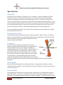
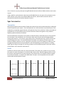
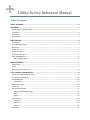
Utility Survey Reference Manual Table of Contents ABOUT THIS GUIDE ............................................................................................................................3 HARDWARE .......................................................................................................................................3 SERIAL INTERFACES (RS232, USB) ................................................................................................................... 3 I/O PINOUT .................................................................................................................................................. 4 BLUETOOTH .................................................................................................................................................. 4 OPTIONAL RTK ............................................................................................................................................. 4 SPAR FEATURES .................................................................................................................................4 ORIENTATION ............................................................................................................................................... 4 LOCAL REFERENCE FRAME............................................................................................................................... 5 FREQUENCY .................................................................................................................................................. 5 LOCATE SIGNALS ........................................................................................................................................... 5 LOCATE SOLUTION ......................................................................................................................................... 5 NAVIGATION SOLUTION .................................................................................................................................. 5 DUAL-SPAR OPERATION ................................................................................................................................. 6 Spar Synchronization............................................................................................................................. 6 SPAR ACCESSORIES ............................................................................................................................7 TRANSMITTER ............................................................................................................................................... 7 SONDE ......................................................................................................................................................... 7 DATA COLLECTOR CONNECTION ....................................................................................................................... 8 UTILITY SURVEY USER INTERFACE .......................................................................................................8 SURVEY STYLE (TRIMBLE ACCESS MENU) ........................................................................................................... 9 UTILITY SURVEY ROOT MENU ........................................................................................................................ 10 JOB MANAGEMENT ..................................................................................................................................... 10 Data Export ......................................................................................................................................... 11 GNSS STATUS CHECK................................................................................................................................... 12 SPAR STYLE................................................................................................................................................. 12 LINE AND SONDE PANELS .............................................................................................................................. 13 Measure and Attribute Forms ............................................................................................................. 15 Style ..................................................................................................................................................... 16 Offsets ................................................................................................................................................. 16 FIELDSENS VIEW ......................................................................................................................................... 18 Frequency ............................................................................................................................................ 19 Measure .............................................................................................................................................. 19 Signal ................................................................................................................................................... 20 MAP VIEW ................................................................................................................................................. 21 Utility Survey Reference Manual (Trimble Access Version) ADVANCED TOPICS .......................................................................................................................... 22 FEATURE AND ATTRIBUTE CODING ................................................................................................................. 22 FEATURE CODES AND CONFIDENCE ................................................................................................................. 24 MEASUREMENTS AND POINT NAMING ............................................................................................................ 26 Point Manager .................................................................................................................................... 29 TRIMBLE BUSINESS CENTER ........................................................................................................................... 31 LIMITS ....................................................................................................................................................... 32 INTERNAL RTK ............................................................................................................................................ 33 DISTORTED SITUATIONS ................................................................................................................................ 33 FIELD AVERAGING ........................................................................................................................................ 33 STATIC POINT POSITIONING........................................................................................................................... 34 DUAL-SPAR NETWORKING PARAMETERS ......................................................................................................... 34 2 | Optimal Ranging, Inc. January 30, 2013 Utility Survey Reference Manual (Trimble Access Version) About This Guide This document provides an overview of the Optimal Ranging Spar 300 system, and the complementary data collection software called Utility Survey for Trimble Access. This manual assumes that the user already has an understanding of the main functions and menu systems of Optimal Ranging single- and dual-spar modes, Trimble Access and Utility Survey. Included in the manual are specifications for the hardware and software capabilities of the spar and its accessories, a hierarchical explanation of each of the panels of Utility Survey, and an Advanced Topics section for experienced users who want to customize a survey project. Other resources: An out-of-the-box Quick Start guide will explain how to connect and set up a single spar, transmitter or sonde, and data collector. Step-by-step instructions, with process-oriented tips for all major utility mapping functions including Dual-Spar mode, can be found in the User Guide. Video tutorials on the ORI website demonstrate use of several more complicated functions. Hardware The Spar instrument is a NMEA compliant device that connects to either the TSC3 or Trimble Tablet data collectors over USB, Bluetooth, or RS-232. The Spar relies on conventional electromagnetic locating physics, i.e., that an underground metallic conductor such as a cable or pipeline (including plastic pipes with tracer wires) radiates a magnetic field based upon an impressed AC current. Though the physics are well known, Optimal Ranging employs a completely new algorithm called model-based optimization to derive the position of the targeted utility. The most important advancements are that the targeted utility can be positioned from arbitrary vantage points (not necessarily at the peak of the field), and that every result is stated with an expected error derived from the modeling process. Extensions of the model-based method pertain to sonde mapping. Non-metallic conduits, tunnels, sewers, and clay pipes can also be traced by introducing a battery operated magnetic antenna (called a sonde) into the targeted facility. The Spar tracks the sonde as it is pushed or pulled through the pipe from fixed arbitrary locations aboveground. In both sonde and traditional line tracking mode, two spars can be used to track utilities with greater range especially in more challenging terrain, such as when the utility is deeply buried. Serial Interfaces (RS232, USB) A 1.5 meter USB cable for connection between a PC host (USB-A plug) and Spar (10-pin JAE JN2FS10SL2R) is a standard accessory to the product. No hardware flow control (RTS, CTS) is supported. The baud rate is fixed at 115200, with 8 data bits, no parity, and 1 stop bit. 3 | Optimal Ranging, Inc. January 30, 2013 Utility Survey Reference Manual (Trimble Access Version) I/O Pinout The 10-pin I/O connector on the Spar front panel has this pinout: Pin 1 2 3 4 5 6 7 8 9 10 Function Jumper to pin 9 forces all I/O over the host interface cable, else Bluetooth is used Rx – Direct read access from Port B of optional MB100 RTK-GNSS board (115200-8-N-1) Jumper to pin 9 forces auto-network connection to the IEEE802.15.4 network coordinator Spar Tx – Direct write access to Port B of optional MB100 RTK-GNSS board (115200-8-N-1) Tx – NMEA write command and control messages to Spar (includes GNSS, 115200-8-N-1) Rx – NMEA read output data messages from Spar (including GNSS, 115200-8-N-1) Reserved Reserved +5VDC Digital Ground Bluetooth When there is no cable attached to the Spar’s 10-pin header, all I/O traffic is routed through a Bluetooth module (Roving Networks RN-41). This device is very common, and can be paired to virtually any Bluetooth controller using PIN code 1234. Spars with firmware version 12 and lower identify themselves as a Firefly-NNNN, with the 4-digit number representing the last four digits of the Bluetooth MAC address. Newer spars identify themselves as Spar-SSSSS:PPP, where SSSSS are the last 5 digits of the serial number and PPP is the product code. The baud rate of the bi-directional serial data transfer is fixed at 115200. Optional RTK Each Spar can optionally include an Ashtech MB100 professional GNSS board, capable of sub-centimeter RTK precision when provided with a compatible RTK correction stream. All Ashtech commands, queries, and broadcast messages are supported through the same serial or Bluetooth interface. Optimal Ranging’s FieldSens View software module handles all interactions with the Ashtech board, although it is possible to access the MB100 directly through NMEA commands. See the Ashtech user manual: ftp://ftp.ashtech.com/OEM, Sensor & ADU/MB100/. The Ashtech board is highly recommended for positioning using Navigation Solution Each spar includes a fully tilt-compensated 3-d digital compass, allowing quasi-stationary orientation measurements. The pitch and roll values are used by the firmware to compute the Locate Solution. The digital compass heading value permits rotation of the target utility offset value (part of the Locate Solution) to Easting and Northing values after correction by the local magnetic declination. This permits the host controller (e.g., FieldSens View and Trimble Access) to combine the utility offset with the current geospatial solution, so that the targeted utility is presented in a geospatial context. Dual-Spar Operation. 4 | Optimal Ranging, Inc. January 30, 2013 Utility Survey Reference Manual (Trimble Access Version) Spar Features Orientation Normally, the Spar is affixed to a range pole, cart, or mounted on a tripod. If handheld, the relative motion of the Spar is assumed to have low dynamics. In contrast to conventional utility locating methods, the mapping process does not require finding the “peak” or “null” points in the field, this occurs from any perspective or orientation, as long as the received signal has enough strength. In some cases the locate accuracy deteriorates as the Spar moves away from the peak of the signal, as indicated by increasing confidence bounds. In those cases the Spar should be kept within about a meter of the peak. The orientation of the Spar is measured and applied during the 3-d positioning process. The spar should be oriented within ±75° of vertical for accurate pitch and roll measurements. Heading has an absolute accuracy of ±2°. Local Reference Frame The black power button is always the forward, or positive X direction. Right is positive Y, and down is positive Z. It’s generally wise to view the display facing the positive X direction, so that the orientation of the FieldSens View map is aligned with the direction of travel and that the spar faces forward. Frequency For accurate utility mapping, it is preferred to use as low a frequency as possible to minimize distortion and signal bleedoff. The Spar hardware supports active and passive mapping at selected frequencies from 22 Hz to 9.82 kHz. When the utility is in poor condition (sheath or insulation faults), or when a reliable ground return path cannot be achieved (dry earth, or unknown far-end ground connection), a higher frequency may be selected. The Spar features a narrowband filtering engine that provides quadrature demodulated magnetic field strengths for six channels (two 3-axis magnetic sensors). All channels are optionally averaged with user selected smoothing parameters. Locate Signals The spar must be brought within an emanating field from an underground utility before a reliable Location Solution is achievable. The orientation of the Spar can be arbitrary as long as pitch and roll are within ±75° of vertical. Locate Solution The targeted utility can be either a Line (cable, pipeline, metallic duct), or a Sonde (battery operated dipole transmitter). If Line mode is selected, the utility must carry an actively applied current from a transmitter at a compatible frequency (by direct or inductive coupling), or is passively carrying a current 5 | Optimal Ranging, Inc. January 30, 2013 Utility Survey Reference Manual (Trimble Access Version) from an external source (like an AC power line that can be traced at 50 or 60 Hz, or the rectified AC signal at 100/120 Hz). Navigation Solution Each spar includes a fully tilt-compensated 3-d digital compass, allowing quasi-stationary orientation measurements. The pitch and roll values are used by the firmware to compute the Locate Solution. The digital compass heading value permits rotation of the target utility offset value (part of the Locate Solution) to Easting and Northing values after correction by the local magnetic declination. This permits the host controller (e.g., FieldSens View and Trimble Access) to combine the utility offset with the current geospatial solution, so that the targeted utility is presented in a geospatial context. Dual-Spar Operation A second rover spar (in addition to a base spar acting as the coordinator) can be set to collaborate in a dual-spar network, using the internal IEEE 802.15.4 wireless module. Collaborative measurements facilitate positioning deeper utilities (those running under rivers, for instance) without significant compromise in relative accuracy, using either a sonde or a transmitter. The presence of the RTK-GNSS hardware option is highly recommended for multi-spar measurements. This allows the 3-D baselines between spars to be autonomously computed. The baseline measurements are used in the processing of the multi-spar positioning of a utility line or sonde. Each collaborating spar must have the same PAN Id (set in the Trimble Access user interface) and an identical list of permitted channels to scan. The base spar (identified by a “B” on the end of the serial number) will have a cable or Bluetooth interface to the data collector, and the rover (end) spar must have an ORI-supplied dongle (or dongle-end of the cable) attached to the 10-pin I/O connector. In Moving Baseline mode, either spar can be moved during the measurement, although it will take a few seconds for the system to readjust tracking positions. The Ashtech RTK board is multi-constellation, employing both GPS and GLONASS satellites. This greatly improves the ability of the system to establish a relative position and time fix, even near buildings and under foliage cover. No external base station is required, and the system will track a sonde or position a deep pipeline from arbitrary vantage points. Placement of the spars can be optimized for GNSS coverage, even while the targeted utility is in a location that may not offer good satellite visibility. In the absence of the Ashtech RTK option, the two spars may be connected using a 4-meter synchronization cable (part number T3P-SPARSYNC). In this case, however, the spars will not automatically readjust tracking positions and the position of the end spar must always be calculated in relation to the base. For more information on spar separation methods, see the Spar Separation video tutorial. Spar Synchronization The presence of the RTK-GNSS function on each spar also permits synchronous measurement processing across the dual-spar network, since each spar independently synchronizes to the GPS time signal. As 6 | Optimal Ranging, Inc. January 30, 2013 Utility Survey Reference Manual (Trimble Access Version) such, to function correctly, two spars using RTK boards must each utilize a GNSS transceiver and receive a signal. Using a cable for synchronization rather than the RTK-GNSS function, the spars will synchronize via the cable. However, they cannot use individual GNSS transceivers, and the cable connection will not automatically calculate the baseline between the spars. Spar Accessories Transmitter ORI supports popular locate transmitter frequencies under 10 kHz, and provides optional pre-calibrated custom frequencies upon request. The Vivax-Metrotech Loc-10Tx transmitter is provided as part of the standard kit, and provides a good selection of frequencies from 32 Hz to 9.82 kHz. When connected to a compatible line, the VX5 clamp accessory to that transmitter allows tracing with a clamp-induced frequency (often 8.192 kHz or 8.44 kHz). The Vivax-Metrotech transmitter has a number of relevant features, about which more can be found in the transmitter’s User Handbook or the Transmitter video tutorial on the Optimal Ranging website. Among other features, it can transmit a signal along a line in three different ways, and can transmit up to two frequencies at once. This is useful because occasionally one frequency will work better than another at different points on the line. Setting the transmitter to omit two frequencies allows the user to toggle the frequencies that the spar detects in the field depending on which frequency is reading higher signal strength. Strategies for choosing a frequency and manipulating other transmitter options can be found in the Transmitter video tutorial. Sonde A sonde can often be used in place of a locate transmitter if the utility line is unable to carry a current. The system can track the progress of a sonde through a pipe or duct. Optimal Ranging sondes are ideal for the Spar, with frequencies for general purpose, non-metallic ducts, and metallic conduits (ranging from 32 Hz to 8.44 kHz) , as shown in the table below. The Spar is also compatible with many other sonde models operating below 10 kHz. Mechanical Dimensions Frequency Advantage Power Battery Life Max Range 180 mm x 53 mm 982 Hz Low Distortion 9V Alkaline 4 hours 25 ft. (8 m) Medium Range 9V Alkaline 4 hours 40 ft. (12 m) General Purpose 180 mm x 53 mm 8.44 kHz 152 mm x 22 mm 8.44 kHz Non-Metallic Duct 305 mm x 22 mm 8.44 kHz Small Size 3.7V Li-Ion 4 hours 40 ft. (12 m) Long Range 3.7V Li-Ion 4 hours 80 ft. (24 m) Low Distortion 3.7V Li-Ion 4 hours 60 ft. (18 m) 320 mm x 32 mm 512 Hz 320 mm x 32 mm 32 Hz Low Attenuation 3.7V Li-Ion 4 hours 25 ft. (8 m) 320 mm x 32 mm 32 Hz Low Attenuation 12V External Indefinite 35 ft. (11 m) Metallic Conduit 7 | Optimal Ranging, Inc. January 30, 2013 Utility Survey Reference Manual (Trimble Access Version) Pitch and yaw are physical parameters of the sonde, which creates a dipole magnetic field. The spar estimates not only the 3-D position but also the orientation of the sonde, which can sometimes be important, as to measure the slope (pitch) of a drain pipe or the direction in which a sonde is moving (yaw). The pitch and yaw are shown on the FieldSens View sonde model screen, and logged in note records for point management. Data Collector Connection Typically, the data collector will be either a Trimble Tablet running Microsoft Windows 7 or a TSC3 running Microsoft Windows Mobile 6.5. The Spar can be connected to either data collector via the provided USB cable or through a Bluetooth connection. The Tablet also offers a an RS-232 connector and can be connected via a normal serial cable (not provided). Since the Bluetooth connection may interfere slightly with the field measurements at some frequencies, one of the cable connections is preferred, especially in low signal or high noise situations. Driver installation for the USB cable is normally automatic. This is done through an internet connection on the Tablet, where Microsoft Windows will automatically locate and install the driver the first time the cable is plugged into one of the USB ports. If an internet connection is not available, the driver can also be downloaded from http://www.ftdichip.com/Drivers/VCP.htm and installed manually. Once the driver installation completes a virtual COM port for the cable is automatically designated in Windows. If the COM port is not displayed at the end of the installation it can be determined by locating an entry for “USB Serial Port” the Ports group in Windows Device Manager. The user should note the COM port number, since it will need to be entered later in the Spar Style dialog. The TSC3 does not require an internet connection to install the cable driver since it is installed along with the Utility Survey software. In rare cases this installation is not successful, in which case the TSC3 prompts for a driver name the first time the cable is plugged into the USB port. In this case, the user should enter the driver name as “ftdi_d2xx.dll” (without the quotes) or, if that does not work, as “\\Windows\\ftdi_d2xx.dll”. To use the cable connection, select “Cable” as the COM port in the Spar Style dialog. Alternatively, the Data Collector can pair with the Spar over Bluetooth, using a direct RFCOMM Profile. The Spar first needs to be paired with the device using the Windows Mobile Bluetooth settings. The Spar will appear as Firefly-NNNN, where NNNN is a 4-digit number representing the last four digits of the Bluetooth MAC address, or as Spar-SSSSS:PPP, where SSSSS are the last 5 digits of the serial number and PPP is the product code. The PIN code required to complete the connection is always 1234. Once paired, the Bluetooth identity can be selected in the Spar Style dialog. 8 | Optimal Ranging, Inc. January 30, 2013 Utility Survey Reference Manual (Trimble Access Version) Utility Survey User Interface Utility Survey is a software data collector for utility line points. Using ORI’s model-based optimization technology as embodied by the Spar, utility line coordinates are rapidly collected from arbitrary positions aboveground. Each collected point is georeferenced per the measured offset, range, and depth to target, and associated with horizontal and vertical RMS values that are a function of detected underground electromagnetic signal distortion. The standard Line and Sonde modes in the Utility Survey plugin are used to capture underground cable or pipe geospatial positions. A blue line is used to show the estimated position of the underground utility. An optional red line can also be activated (select “Spar Pt” on page 3 of the Line or Sonde panel) to show the aboveground GNSS position of the spar as it is moved down the lay of the line. In both cases, a lighter colored line indicates reduced confidence, as when the spar moves significantly away from the line (resulting in a lighter blue line), or when it is under foliage cover (resulting in a lighter red line). The operator need only maintain casual contact to the line when collecting positions – the system operates effectively from offset positions from the utility line. Once licensed, Utility Survey appears at the Trimble Access top level. Utility Survey leverages all Trimble Access settings, Survey Styles, Feature Libraries, Coordinate System selections, Base maps, GNSS receiver management, Point database management, etc. This document presumes that those features are understood by the user, and if not, Trimble documentation is used as a reference. Utility Survey uses the Trimble Access SDK to provide an integrated user experience. All aspects of the Spar measurement are controlled from the Trimble Access environment, as shown. Utility Survey is embedded within Trimble Access, and communicates with the Spar through an ORI software module called FieldSens View. The role of Utility Survey is to combine Spar hardware measurements with Survey Core functions to result in a Job database holding geospatial positions coupled with the expected accuracy of each point. 9 | Optimal Ranging, Inc. January 30, 2013 Utility Survey Reference Manual (Trimble Access Version) Although the Spar is a standard NMEA 0183 device, all the hardware details are hidden from the Trimble Access user, as will be exposed in the succeeding sections. Survey Style (Trimble Access menu) Utility Survey uses the GNSS receiver antenna height to determine the offset to the Spar center (exact center of the carbon-fiber handle). Positioning the underground utility is always relative to the center of the Spar, so the geospatial position of the spar must be known to present the utility position in geospatial coordinates. Since the Spar includes on-board pitch and roll orientation sensors, the offset of the GNSS antenna from that point can accommodate a non-vertical pole. It is sometimes convenient to set the antenna height in the Survey Style, as well as the height measurement method. If it is not set in the Survey Style, then it can be set by clicking on the Antenna icon in the Utility Survey main screen or in the Measure Point dialogs within Utility Survey. Note that when the automatic measure and store operations are enabled in Utility Survey the antenna height must be set before a measurement is attempted. Otherwise a warning will be displayed and the measurement will be aborted. Utility Survey Root Menu Upon entering Utility Survey from the Trimble Access menu a start page is displayed. The following operations are possible from the start page: 1. 2. 3. 4. 5. Create or Open a Job Check GNSS status Define Spar Style Enter Line mode a. Single-Spar line positioning b. Dual-Spar line positioning Enter Sonde mode a. Single-Spar sonde tracking b. Dual-Spar sonde tracking Line and Sonde modes have similar structures, but some key differences and inputs. When the functions are similar, they will be described simultaneously, but major differences will be highlighted. Job Management Before choosing a mode, create a new Job, choosing the correct coordinate system and units: 10 | Optimal Ranging, Inc. January 30, 2013 Utility Survey Reference Manual (Trimble Access Version) Notice that we’ve linked the “ORI.fxl” feature code library, which can be edited or replaced by an alternative as long as the utility and spar line codes are present (see Feature Codes). Once a Job is created and accepted, it will be the default until a new job is created or a previous job is opened. New Jobs are continuous from previous jobs in the sense that point numbers will automatically begin after the last-used number from the previous job. This number, however, can be changed by the user for facility of identification. Data Export Direct DXF export of the utility data can be invoked from the Job menu, or a softkey in the Line mode panel. ORI provides a modified Trimble style sheet to directly export the data to DXF, although a more common method is to move the data into Trimble Business Center for processing prior to exporting to a CAD format. All the relevant utility and spar position information can be exported to Excel-compatible CSV files using two buttons accessed from the Job icon at the top level Utility Survey panel: 11 | Optimal Ranging, Inc. January 30, 2013 Utility Survey Reference Manual (Trimble Access Version) GNSS Status Check The “Status” selection from the Utility Survey root menu will confirm the functionality of the GNSS rover, as defined in the Survey Style in Trimble Access. Status provides updates on how many satellites the rover sees, PDOPs, and metrics for the quality of the position. Spar Style Before any Utility Survey can begin, the correct frequency of the transmitter or sonde must be entered on page 1 of the Spar Style dialog. Page 1 also includes options for Internal RTK and Field Averaging. In addition, the “RMS Type Select” menu defines whether one or two distinct lines are saved at the measured utility positions. The lines are coded by the five confidence levels defined as part of the Feature Codes, and can be separately saved according to horizontal or vertical confidences. These end up as distinct layers in the resulting 12 | Optimal Ranging, Inc. January 30, 2013 Utility Survey Reference Manual (Trimble Access Version) data, so it doesn’t hurt to save both, unless there isn’t a need to resolve position errors both vertically and horizontally. The connection parameters to the Spar need to be setup on page 2. For Bluetooth connections, or USB cable connections on the Trimble Tablet, enter the COM port number obtained in the pairing (Bluetooth), or cable installation process (USB cable). For Bluetooth connections on the Trimble TSC3, select the Bluetooth ID discovered in the pairing process. The TSC3 USB cable is special. Utility Survey includes a special driver that needs no special installation. “Cable” is used in the Spar Style dialog to signify that the USB cable is being used on the TSC3. Note, on the TSC3, USB operation is recommended because the Trimble GNSS receiver is also connected via Bluetooth. Depending on data rates, the Bluetooth interface may be a little more sluggish than when the Spar is connected by cable. The number of spars in the network is also defined on page 2 of Spar Style. The Spar Style window is also accessible from the Line/Sonde panels using a softkey, but the second page (COM# and spars in network) will be read-only. Line and Sonde Panels The Line and Sonde Panels serve as the monitoring and control user interface for Line and Sonde modes. From here, the utility or sonde position (relative to the aboveground spar) can be monitored along with the observed measurement confidences. Together with the Map and the locating panel called FieldSens View, the Line/Sonde panels facilitate management of all setup and point/line measurement functions. Although the units shown here are metric (following the choice of UTM coordinates), positions can be displayed in feet as defined in the Job and the Offsets dialog. Note that when the Line or Sonde icon is clicked from the Utility Survey screen, the FieldSens visual representation of the spar and utility line is displayed before setting survey specifications or making any geospatial recordings. Hide FieldSens to manipulate Line/Sonde panel functions. 13 | Optimal Ranging, Inc. January 30, 2013 Utility Survey Reference Manual (Trimble Access Version) From the Line/Sonde mode panel, the user can enter FieldSens View, the Map, Continuous Topo mode, or End the Survey. In addition, access to other setup and status functions is provided through softkeys (over three pages). On the first page, a checkbox is present to use Limits, which are thresholds that control what utility position points are logged in the Job (defined on the second page). The third page of the Line/Sonde panel allows the user to set up a number of point and line options: 14 The Measure and Attribute forms can be turned on to appear when a Line, Point, or Peak is measured. The user may designate the starting point number, which will automatically increase as each point is collected, and is continuous even over different Jobs to ensure that point numbers are not duplicated. The “Repeat Pt” checkbox allows multiple measurements that will all have the same point name. | Optimal Ranging, Inc. January 30, 2013 Utility Survey Reference Manual (Trimble Access Version) The “Spar Pt” checkbox will direct the program to record the position of the spar aboveground, eventually displaying the positions of both the utility (blue line) and spar (red line). The “GNSS Fix” checkbox activates a function that requires a GNSS fix for all positions measured. The “Model Fix” checkbox can be used to determine whether distortion is present in the field The Utility Feature to be measured can be defined from a list of features as defined in the feature code library. Choosing a feature from the dropdown menu prompts entry of a number of different data, also as defined in the feature code library. Lastly, as a useful way to monitor the Spar battery, connection status, to display the serial number, and firmware update status, click the About button from page 1 of the Line panel: Measure and Attribute Forms While using Utility Survey, entry forms are presented during the data collection phase according to the feature library. The user can control which entry forms are presented on page 3 of the Line and Sonde setup panels. Checkboxes can be selected to use two forms for measurement (Measure or Attribute) when measuring a Line, Point, or Peak. 15 | Optimal Ranging, Inc. January 30, 2013 Utility Survey Reference Manual (Trimble Access Version) When MeasForm is checked for any of the three utility measurement methods (Line, Point, or Peak), the standard General Survey measurement form will pop up upon invoking that measurement. This permits maximum flexibility in controlling measurement times, quality levels, feature code choice, attribute entry, and precision tolerances. The AttrForm group of checkboxes defines the behavior of pop-up attribute entry on each point measurement. For each utility measurement type (Line, Point, or Peak), only one form type will pop-up (either the Measure Form or the Attribute Form). It is sometimes more convenient to select only the Attribute Form when the measurement parameters remain the same. At the bottom of page 3 of the Line mode setup is an entry called Utility AutoMeas feature. Any Feature code currently present in the selected feature library (FXL) can be selected by clicking on the entry box. Once selected, this code is prepended to every utility point. Most commonly, this code will signify the name and type of the tracked utility, e.g., Gas, Electric, Water, etc. When the selected code becomes active as an AutoMeas feature, a prompt appears so that attributes (if present in the FXL) of the line can be entered. Typical attributes of a feature are Owner and Diameter (if the utility is a pipeline). The entered attributes at the time of AutoMeas feature selection are stored be default on every subsequent point. The attributes can be modified from within the Measure Form or Attribute Form. If neither the Measure Form nor the Attribute Form is checked for a particular measurement type, the point is silently measured and stored in the Job database. The AutoMeas feature and default attributes are still stored with the point. For more information on feature coding and point measurements, see the Advanced Topics section. Style The Spar Style parameters, equal to the Spar Style window accessed from the root menu, may be entered by selecting the Style softkey from the Line/Sonde panel. The second page of those parameters is set to Read Only, as these values (COM port, and Dual-Spar networking parameters) can only be set outside of any measurement mode. Frequency is a fundamental parameter that must match what is selected at the transmitter, and can be set from the Style dialog, as well as directly from FieldSens View. This is useful for when two frequencies are emitted simultaneously down the line, meaning that the user can change the frequency the spar reads from within Utility Survey, without having to return to change the transmitter settings. The Spar Style dialog groups frequencies by commonly available sets offered by several manufacturers. 16 | Optimal Ranging, Inc. January 30, 2013 Utility Survey Reference Manual (Trimble Access Version) Offsets An offset must always be entered from the spar (center of the carbon fiber handle) to the antenna and to the ground. Offsets are always entered in “spar coordinates”, i.e., XYZ, where positive x is forward, positive y is right, and positive z is down. Thus for a spar that is mounted on the pole with the black switch facing outward away from the pole, the offset from spar to antenna is -10 cm (using the standard quick release brackets). “Spar height” is the z offset, and may be expressed without a +/- sign. The height of the antenna is also displayed as read-only, having been entered previously (see Survey Style). When using a GNSS rover in single-spar mode, the reference frame can be Relative because the system will compute the spar location based on the rover’s position. However, an Absolute reference frame may be used if the spar will remain in a fixed, known geospatial location. In this case, the location will be entered on the Line panel, where a “Base Spar” button will appear. For a visual explanation of offsets in single-spar mode, see the Offsets Tutorial. In the event that a different display unit (m, sft, in) from the chosen coordinate system is desired for FieldSens View values, this can be changed on page 1 of the Offsets dialog. For pipelines, since Utility Survey always measures depth to the center of the pipe, it is possible to offset that value by the radius of the pipe. Set the appropriate utility diameter, as well as whether the offset should be to the Top, Center, or Bottom of the pipe. The utility diameter is set when the reported depth of a pipeline should be to the top or bottom of pipe, rather than the center. Offsets in Dual Spar Mode When using two spars, the user must decide a mode of spar separation. Spar separation distance is normally computed automatically by the RTK moving baseline feature. When the system is used indoors, when GNSS signal coverage is poor, or in the case of using spars without Ashtech RTK boards, the offsets can be measured manually. Once again the measurements are performed in spar coordinates, relative to the center of the base spar handle. Dual-spar mode can be turned on by setting the number of spars to 2 from page 2 of the Spar Style dialog. From the dropdown menu “Spar separation” on the Offsets screen, you will need to select Relative, Absolute, or Moving Baseline. These three options are described below. Relative (XYZ) Spar Separation 17 The location of the End spar will be expressed in xyz coordinates relative to the position of the Base spar by manually measuring the distances. After choosing Relative spar separation, a “Base Spar” button should appear on the Line or Sonde panel, prompting for the geospatial | Optimal Ranging, Inc. January 30, 2013 Utility Survey Reference Manual (Trimble Access Version) location of the Base spar. Absolute (ENU) Spar Separation Absolute mode requires no measurement of the relative position of the end spar, but assumes you have access to geospatial coordinates for the positions of both the Base and End spars. The positions of the Base and End spars can be entered using the buttons that appear when Absolute mode is selected. Moving Baseline Spars with Ashtech RTK boards will automatically calculate their locations based on a GNSS rover and the connection between the spars. No input is needed from the user. For more practical information about how to calculate spar separation, see the Spar Separation video tutorial. FieldSens View FieldSens View is a Windows (XP/7/Mobile) application used for setting up the spar to make measurements, and for viewing the location results in the local reference frame. The Windows Mobile version of FieldSens varies slightly in form from the Windows XP/7 version, but this difference is minor and only the Mobile version is described here. 18 | Optimal Ranging, Inc. January 30, 2013 Utility Survey Reference Manual (Trimble Access Version) FieldSens View provides two perspectives of the utility, both of which are relative (not geospatial). On the left in the Top View, the current spar position is presented as a gold triangle, with the utility position shown as the solid blue line (Line mode) or a blue dot with a short line through it (Sonde mode). At the top left, the overall magnetic field signal strength is shown in dB (decibels). The right side of the FieldSens View display is a side view of the sonde or down the line, with the red box indicating the RMS confidence region of the measurement. The green “+” indicates the spar position above the ground. Signal strength (dB) and current (Amps) are different measurements. Signal strength will always indicate the strength of the 2-D magnetic field around the utility line as a function of where the spar is with respect to the line. Current, on the other hand, is a physical parameter—how much current is flowing through the line—and the reading can only be trusted when the blue model line or sonde icon is stable. FieldSens View has a number of softkeys. Frequency The frequency that the spar detects can be changed or toggled to the last used value using the softkey that displays the current frequency. This is useful in Line mode when the transmitter is set to output two simultaneous frequencies, as is possible with the Loc-10Tx from Vivax-Metrotech, or the Metrotech i5000 transmitter. Using two frequencies can help to validate system positioning accuracy in areas of distortion, when the RMS confidence is poor at one or both frequencies. Measure The Measure key initiates all five types of point measurement, with the “Measure Aboveground Point” function bringing up a form to permit modification of the point name and code. More information about making and customizing measurements (Utility Point, Utility Line, and Utility Peak), and using the Point Manager to view measured points, can be found in Advanced Topics. Continuous Topo Continuous Topo mode can be used very effectively for Utility Line surveys, and can be turned on by selecting “Measure” and then “Continuous Topo”. The measurement options are controlled by a 19 | Optimal Ranging, Inc. January 30, 2013 Utility Survey Reference Manual (Trimble Access Version) number of Survey Core measurement interval qualifiers. “Time and Distance” is a good way to control the number of recorded points while maintaining sufficient density to derive structure in the surveyed utility. Note that Continuous Topo is only available when Relative (XYZ) Reference Frame is selected in the Spar Style dialog since it requires an active GNSS connection. Both these dialogs permit modification of the Point Name and Code. For Continuous Topo measurements, it’s recommended to use a numerical point number from which all the automatic line coded points are derived by prepending a “V” to the number. Signal FieldSens View does not present conventional locating parameters like Peak and Null. There are times, however, that the model-based solution is invalid. This can happen when there is not enough AC current flowing on the utility line, or when the Spar is too far away from the line. In this situation, the blue bar (representing the underground utility), flashes at about a 1-second rate on and off. Rather than guiding the user to the line using Peak/Null indicators, FieldSens View employs a method called Spatial Locating. Using the fact that a GNSS position is always present (even if not fixed or has poor quality), the overall signal level (in dB) is mapped as the user traverses the environment. 20 | Optimal Ranging, Inc. January 30, 2013 Utility Survey Reference Manual (Trimble Access Version) Selecting the “Signal” softkey will turn on the Spatial Locating function. The color of the signal ranges from blue through yellow to red. Progressive movement in the direction of higher signal level causes the shade of the colored disk to move toward orange and red; movement away from the higher signal will cause the colored disk to turn more blue. Usually when the disk reaches orange or red, if the detected signal change is due to the target utility being detected, the model-based solution locks in, and the blue bar stops flashing. The user may specify the range of the signal differential, from 1dB to 10dB. Spatial Locating can easily be reset by tapping “Clear Screen.” Map View The map shows the geospatial view of the utility measurements you have made rather than the FieldSens relative model view of the utility. The user can zoom, pan, and manipulate the map using the bottom softkeys. “Filter” will allow a filter of certain types of points; “Options” will allow control of the code displayed for each point. The map will display a blue line of varying shades to represent the utility line. If you selected “Spar Pt” on page 3 of Line/Sonde, the map will also display a red line of varying shades to represent the spar’s changing position. Shading indicates confidence: darker colors mean greater confidence, while lighter colors mean lower confidence. Four of the five point measurement options (all except Continuous Topo) are present by holding down the cursor within the Map as long as the “hand” icon is not selected. 21 | Optimal Ranging, Inc. January 30, 2013 Utility Survey Reference Manual (Trimble Access Version) When in the Map, it is sometimes difficult to get back to FieldSens View. Notice that the context sensitive menu has a item “Open FieldSens View”, which can be used to switch back to the locating screen. Because of technical differences between the Trimble Access Survey Core functions, and FieldSens View, the “Switch to” list does not include FieldSens View. Advanced Topics Feature and Attribute Coding The feature and attribute coding capabilities employed in Trimble Access are useful for effective recordkeeping of field information and editable using the Feature Definition Manager in Trimble Business Center (TBC). Feature coding is the process of archiving relevant fieldbook information about the collected point data, and maintaining that information through the various workflow processes. Now, in version 1.4 of Utility Survey, the full power of feature and attribute coding fully supports these capabilities. 22 | Optimal Ranging, Inc. January 30, 2013 Utility Survey Reference Manual (Trimble Access Version) Optimal Ranging provides the “ORI.fxl” feature code library to allow automatic line construction during data collection. While the feature codes present in the provided library ORI.fxl are categorized as “Utility Survey”, the actual pneumonic code value must still be unique within an expanded list as is usually the case for typical application scenarios. The list can include many other codes that represent aboveground features, in addition to the underground utility line. It is also in this feature code that aspects of the Measure and Attribute forms are defined. With regards to attribute records, note that all the Line Util Vert n: and Point Util Vert n: codes are set up in the FXL by default to include three attributes called Depth, HSDV, and VSDV. Whenever these codes are assigned (levels 1-5 based on the measured RMS confidence of the point), Utility Survey will save the current value of depth (of cover), and the horizontal / vertical standard deviations of the point. These are just three of the ten values that can be written as attributes. Edit the FXL to include additional keys to save additional information. 23 | Optimal Ranging, Inc. January 30, 2013 Utility Survey Reference Manual (Trimble Access Version) In some cases, ORI.fxl sufficiently covers the application requirements as is, without modification. If not, feature codes may be augmented, changed or merged using TBC. For instructions on how to make these changes, refer to Application Note AN101. The ORI.fxl feature code may also be modified outside of TBC using Utility Survey’s Feature Library editor, accessed from the Settings icon at the Trimble Access top level. Feature Codes and Confidence The “ORI.fxl” feature code library allows automatic line construction during data collection, which is how the blue Utility position model line can be displayed live. These codes can be merged with existing tables as needed, and the .fxl file name changed (this is specified in the Job Settings). Any of the code names can be modified as necessary, as long as the description field remains unchanged, up to and including the “:”. 24 | Optimal Ranging, Inc. January 30, 2013 Utility Survey Reference Manual (Trimble Access Version) Field codes are also used to capture overall accuracy of the utility survey in five accuracy levels, by assigning lighter colors for the blue (utility) or optional red (spar) line positions to depict lower confidence in the result. The distances shown in the description field are the RMS error thresholds that define the separation between color coded layers for the coded utility and spar line positions. These can be changed as required. For example, the confidence levels VA-VE represent the 1-σ vertical RMS error of the utility line, over the range from a low of 10 cm (VA) to a maximum of 2 m (VE). Positions that have errors larger than 2 meters will be uncoded (they are above the highest threshold). For dual spar line mode measurements, a deep pipeline may result in some points that are outside that tolerance band. To accommodate this situation, the description fields can be modified to expand the range of allowable errors while still automatically coding the point as part of a utility line. This is the full list of codes: 25 | Optimal Ranging, Inc. January 30, 2013 Utility Survey Reference Manual (Trimble Access Version) Separate codes are used for Horizontal and Vertical confidences, which are not necessarily the same. There is an option available from the Style softkey that instructs the system to save lines representing the utility position, with the colors reflecting Horizontal, Vertical, or Both confidences. When the selection is Both, then two utility lines are saved to the job database. During export to a CAD file (like DXF), this permits both lines to be saved to a different layer so that they can be selectively viewed. The HA-HE codes indicate the relative horizontal confidence of the line, while the VA-VE codes reflect the vertical confidence. Keep in mind that point names for underground utilities are all prepended with a “V.” This “V” does not indicate a vertical confidence code, but rather the name of the point. NOTE: Don’t confuse the color of the utility line on the Trimble Access Map with what might be exported using a custom style sheet. The Map View is used only for viewing the data as it is acquired, and the colors are an easy way to detect areas of poor confidence. After data collection is complete, a custom style sheet can govern the color of the utility as written to a layer in the output file. For example a gas line might be colored yellow, and the two highest quality levels allocated to a solid yellow line, with the three lower quality levels shown as a dashed line. The ORI.fxl feature definitions are also used within the Feature Definition Manager in Trimble Business Center to process the feature codes of imported Utility Survey Jobs. Measurements and Point Naming A lot of points can be generated by Utility Survey, particularly in Continuous Topo mode. Utility Survey definitions of Point Measurements, Position Types, and Point Naming must be examined: Utility Survey permits making point measurements in five ways: Point Measurement Definition Measure Utility Point (UP) Make a single point measurement of a utility line (not line coded) Measure Utility Line (UL) Make a single point measurement of a utility line (line coded) Measure Aboveground Point Make a single point measurement of an aboveground point (manhole, valve, paint mark, etc.) Measure Continuous Topo Utility Line Make a series of point measurements of the utility line while walking (line coded, and subject to limit thresholds) Measure Utility Peak (UK) Make a point measurement of peak signal position at a specific point (using Model Fix mode if needed) 26 | Optimal Ranging, Inc. January 30, 2013 Utility Survey Reference Manual (Trimble Access Version) The software automatically merges measurements from the GNSS and Locating subsystems. To correctly document and provide an audit trail for each resulting merged position, multiple positions are recorded for each 3-D utility point measurement. The following table describes these positions: Position Type Reference Recorded Where Definition Antenna Height Relative Antenna Height of antenna base or center Record (both height and method are entered by user) (user entry) Spar Height Relative Offset form Height of Spar center (mid-handle) over ground when the Spar is (user entry) vertically oriented on the range pole Utility Relative Offset and Depth Utility Point Position of the underground line from the Spar to Ground point, in Note spar coordinates Record (computed by the software using model-based optimization) Antenna To Geospatial Ground Utility Point Projection of the antenna position onto the ground. Note, since the Reference range pole may not be vertical, this is not necessarily equal to with full QC Antenna Height (measured survey point) Spar To Ground (optional) Spar Point “keyed in” Geospatial Utility Line Geospatial The center of the Spar is the origin of the Spar coordinate system in ENU coordinates. The Spar to Ground point is generated from Antenna to Ground position, Spar pitch, roll, and heading, and the entered offsets of the spar to ground in spar coordinates. The recording of this point is optional and can be turned on using the “Spar Pt” checkbox on page 3 of the Line or Spar panel. The map will then display a line for the spar’s changing position over the ground. (computed by the software) Utility Point Geospatial utility position, after merge of Offset and Depth with the “keyed in” Spar to Ground point. (computed by the software) Measuring a point automatically records two measurements: the location of the Trimble antenna (Antenna-to-Ground) and the underground utility location (Utility Line). A third measurement, the location of the Spar (Spar-to-Ground), is optional and can be turned on from the checkbox on page 3 of 27 | Optimal Ranging, Inc. January 30, 2013 Utility Survey Reference Manual (Trimble Access Version) the Line or Sonde panel. The two default measurements will be precise even without the third, unless the utility pole is tilted, in which case only the antenna position could be altered. With the Spar position measurement turned on, the antenna data will be accurate even when the pole is tilted because the Spar’s pitch and yaw sensors will automatically correct the position reading of the antenna, which has no pitch and yaw sensors. In either case, the accuracy of the underground utility location will never be affected by whether the Spar position measurement is activated. The Spar To Ground position depends on the Antenna To Ground point, plus the entered spar and antenna heights, as well as the tilt of the pole. The Utility Line position depends on the Spar To Ground position, the measured Offset and Depth to the line, and the digital compass heading of the spar. The heading is used to translate offset (measured in the X-Y Spar frame) to Easting and Northing in the chosen coordinate system. The Antenna-To-Ground point is a native Trimble Access record point, with full QC metrics. For example, at right, point UL101 is an Antenna-To-Ground point. There was no Spar-toGround point recorded. Point VUL101 is an underground Utility Line point that does not have recorded quality control or antenna data, because it is referenced to UL101. So, there can be up to three points recorded in the Job database for every measured point (two are recorded by default). A user interface dialog (presented later) allows selection of the line coded points to generate layers for the horizontal confidence of the measurement (H1..Hn), the vertical confidence (V1..Vn), or (by default) layers representing both horizontal and vertical confidences. Position Type Antenna to Ground Spar To Ground (optional) 28 Point Measurement Point Base Name Measure Utility Point UP1..n (starting index chosen by user) Measure Utility Line UL1..n (starting index chosen by user) Measure Aboveground Point arbitrary name, e.g. “MH1” Measure Continuous Topo Utility Line arbitrary name, e.g., “1”, or “10000” Measure Utility Peak UK1…n (starting index chosen by user) Measure Utility Point SUP1..n (starting index chosen by user) Measure Utility Line SUL1..n (starting index chosen by user) Measure Aboveground Point Not recorded Measure Continuous Topo Utility Line “S”prefix, e.g., S1 Measure Utility Peak SUK1…n (starting index chosen by user) | Optimal Ranging, Inc. January 30, 2013 Utility Survey Reference Manual (Trimble Access Version) Utility Line Measure Utility Point VUP1..n (starting index slaved to UP1..n) Measure Utility Line VUL1..n (starting index slaved to UL1..n) Measure Aboveground Point Not recorded Measure Continuous Topo Utility Line “V”prefix, e.g., V1..n Measure Utility Peak VUK1…n (starting index slaved to UK1…n)* * In previous software versions, this measurement was contained in two points beginning with H and V. Arbitrary point base names are chosen by the user for the Continuous Topo Line, and Aboveground Point measurements (each of these have a dedicated Measure Form for arbitrary setting of the name). A chosen name should always end with a numeric digit, to allow intuitive point auto-incrementing. For Measure Utility Line, Measure Utility Point, and Measure Utility Peak, the starting index is set by the user to allow non-overlapping point names across multiple jobs. The table above shows the point base names chosen by the system for the various position types and point measurement modes. Point Manager The point manager displays all points, including metadata, that were recorded during the job, and can be accessed either from Favorites in the Line/Sonde panel or from the Job screen. All metadata points (limits, offsets, spar style, etc.) are recorded in the beginning of the job, and not recorded again until changed. Points are displayed with their custom names, all underground points having the prepended “V” in addition to the kind of point measured and the number assigned or chosen by the user. The code for the point (horizontal and vertical confidences, as well as a tag for a line begun or ended) and geospatial coordinates are included as well. 29 | Optimal Ranging, Inc. January 30, 2013 Utility Survey Reference Manual (Trimble Access Version) To generate a customized report, choose the Export button (Job screen), and select "Export Utility Attribute CSV". The points and all the attribute information are exported, as well as user comments that are attached to the point. User comments can be added from Favorites on the Line/Sonde panel. Note Records The Trimble Access Job database holds discreet points representing the Antenna-To-Ground, Spar-ToGround (optional), and Utility Line positions. The Antenna Height and Spar Heights are user-entered, and remembered as part of the restored last state of the Utility Survey application. The remaining Position Type (“Utility Offset and Depth”) represents the relative position of the utility line from the Spar-To-Ground point. These values, and their relative confidences, are recorded within a Utility Line (“V” prefix on the point name) Note Record in the Job database. Sometimes it is useful to look at the utility position in relative coordinates. For example, Depth is generally stated as relative to the ground, and the Note record can be viewed to see the depth value (and depth precision), rather than the utility elevation in geospatial coordinates. The Depth and Current values are also used within the Utility Survey product to create Profile views, i.e., a plot of the depth and current over linear distance down the line. Utility Survey offers standard .CSV export of the full results of the line survey, including the relative values as read from the Note Records. Alternatively, when directly importing the survey results 30 | Optimal Ranging, Inc. January 30, 2013 Utility Survey Reference Manual (Trimble Access Version) as a .JOB into Trimble Business Center, the Note Records survive the import and customized Style sheet export functions can parse the information contained in the Notes. Trimble Business Center The following figures show how after importing the Utility Survey job into TBC, the layers used for defining RMS confidence in the utility line position are all available for selection on or off. This supplements the color variation to allow a detailed understanding of the measurement results. 31 | Optimal Ranging, Inc. January 30, 2013 Utility Survey Reference Manual (Trimble Access Version) Limits The Limits checkbox on the first page of the Line/Sonde panel activates the Limits functions, which are thresholds that control what utility position points are logged in the Job. If activated, the user may define the thresholds on page 2 of Line/Sonde. If any of the measurement values exceed (or are less) than the corresponding limit, the point is rejected. All the values relate to locating subsystem values, except Max spar HSDV and Max spar VSDV. These are the horizontal and vertical standard deviations of the Spar position, which is directly derived from the GNSS subsystem. These limits are not normally exceeded if the “Fix required” is checked, but permit non-Fixed GNSS operation with appropriate use of these limits. Another useful limit threshold is the “Min signal (dB)”. By stating the signal level in decibels (dB), the useful measurement range remains fixed over a 120 dB range (-10 dB to 110 dB), independent of the active frequency. For those interested in the relationship between magnetic field signal level (h) and dB at frequency f, it is as follows: h f dB 20 log 10 x 200uA / m 491Hz 32 | Optimal Ranging, Inc. January 30, 2013 Utility Survey Reference Manual (Trimble Access Version) Internal RTK Users operating in Dual-Spar mode must choose a type of spar separation, as described above. Only spars with Ashtech boards can be synchronized without a cable, and only spars with the RTK function enabled on the Ashtech boards will be able to operate in Moving Baseline mode. Typically, Moving Baseline requires a GNSS fix using a rover. However, in the presence of wireless internet networks, ORI supports Network RTK. By checking the Internal RTK box on the Spar Style window, the base spar will accept a RTK correction stream passed from the data collector. In this way, the full Moving Baseline system, including both spars, will be geospatially positioned. Distorted Situations All electromagnetic based utility location measurements are negatively affected by distortion in the underground environment. The Spar’s ability to measure the RMS (root-mean-square) error and depth from an offset position can permit improved accuracy even in the face of significant distortion. In all conventional locating equipment, the utility centerline is estimated by finding the “peak” of the magnetic signal strength. Although that is not necessary for the Spar’s model-based methods to estimate depth, the peak signal strength is a useful parameter and can be used to aid the horizontal confidence estimate on a site. When the position of the peak differs from the Spar’s estimated centerline, the error expectation must expand to encompass this divergence. It is also very useful to annotate the peak position in the Job database for later review, since the peak value is often used as the geospatial X-Y position. When in Line mode Utility Survey includes a Point Measurement called “Utility Peak”. This can be used to create a special point in the Job that annotates the peak signal position. Prior to selecting this measurement, the Spar should be moved over ground to maximize the signal strength (dB value) at the top left of FieldSens View. When “Model Fix” (checkbox on page 3 of Line/Sonde) is on, any deviation between the peak value and the currently estimated centerline position is added to the horizontal RMS error for the measurement. This deviation is also logged in the Job for later review. Furthermore, in Model Fix mode, when a signal peak is marked, it’s possible to use the peak as a reference position as the Spar moves across the line. A video tutorial on how to use Model Fix is available on the website. For a full explanation of types of distortion, case studies, and a Model Fix test, see Application Note AN100. Field Averaging Field averaging on all six channels can be selected in Spar Style. For fast response time, use a short average time, or select average Off. For slower response time but improved performance in poor conditions (high noise), increase the average time. Linear averaging (“Avg Lin”) smooths the field over a selected time interval. Exponential averaging (“Avg Exp”) uses a smoothing time constant to determine the relative effect of older data on the new measurement. The default is set to not average. For statically measured points (spar is not moving), averaging will improve performance, especially in noisy environments. 33 | Optimal Ranging, Inc. January 30, 2013 Utility Survey Reference Manual (Trimble Access Version) Average Time means the time period of a single average; Update Rate means the frequency of display updates. Longer average times improve the detection performance of the system, with the tradeoff of increased latency in the system. Sometimes latency is not much of an issue, when the data collector (Trimble Access) is set to log single points after an occupation time of several seconds. In most cases, setting Average OFF (equivalent to setting the linear average time or exponential time constant to one scan) will provide reasonable system response times without sacrificing accuracy. Static Point Positioning When the “Repeat Pt” box is checked on page 3 of Line/Sonde, all measured point names will be the same. This allows a different form of averaging, allowing all point measurements to be averaged in export. A “Repeat Points” feature in the Export screen allows for this, averaging the values of all points that have the same name. This could be useful, for example, when mapping a static sonde experiencing distortion. With “Repeat Pt” selected, the spars can be moved around the sonde to make different measurements, such that all these measurements will be averaged to minimize the effect of distortion on the accuracy of the point measurement. Dual-Spar Networking Parameters Please contact ORI for instructions on how to download the Spar Networking Parameter Utility. This will allow you to change the PAN ID from the default setting to a unique ID for a dual-spar system, and perform channel scans to determine the appropriate channel to use in noisy wireless conditions. This is necessary when you have multiple dual-spar systems in the same area, or in an area with 2.4GHz noise. 34 | Optimal Ranging, Inc. January 30, 2013