1
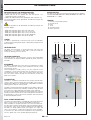
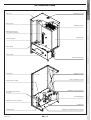
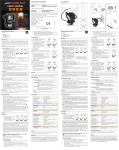
22kw ELECTRIC BOILER
USER MANUAL
All Seasons Hire ltd
Unit 4, Harewood Farm
London Road, Andover Down
Andover
SP11 6LJ
01264 387 370
[email protected]
WHO SHOULD READ THESE INSTRUCTIONS
APPLICABLE STANDARDS
These instructions should be read by:
- the specifying engineer
- the installer
- the user
- the service engineer
ENGLISH
WARNINGS
SYMBOLS
The installation must be in accordance with the current standards.
Essential instruction for
the correct operation
of the installation.
IMPORTANTS NOTES
These instructions are an integral part of the equipment to which
they relate and must be handed to the user.
Essential instruction for
the safety of persons
and the environment.
FRANCAIS
The Boilers have been manufactured to comply with
the following standards BS EN60335-2-35: 2002,
BS EN55014-1: 2001 and BS EN55014-2:1997.
Danger of electrocution.
The manufacturer reserves the right to change the
technical characteristics and specification of its
products without notice.
Danger of burns
The availability of certain versions and their accessoiries
can vary following the market.
RECOMMENDATIONS
Warning : Do not switch ON if there is a possibility that the
water in heater is frozen.
• These instructions are an integral part of the equipment to
which they refer and the user must be provided with a copy.
ESPAÑOL
The manufacturer declines all liability for any damage caused as a
result of incorrect installation or in the event of the use of appliances
or accessories that are not specified by the manufacturer.
NEDERLANDS
The product must be installed and serviced by qualified engineers
in accordance with the regulations in force.
• The manufacturer cannot accept liability for any damage
resulting from incorrect installation or from the use of
components or fittings not specified by the manufacturer.
• Any failure to follow instructions relating to tests and test
procedures may result in personal injury or risks of pollution.
ITALIANO
• The product must be installed and serviced by qualified
engineers, in compliance with current standards.
• It is important to switch the boiler off before carrying out
any work.
DEUTSCH
• There are no user parts inside the control panel.
664Y2700.D
EN • 1
ENGLISH
FRANCAIS
INTRODUCTION
DESCRIPTION OF THE SPECIFICATIONS:
CERTIFICATION
This wall hung electric boiler is available in 5 models:
• Models 09 and 15 are supplied with 400 Volt triphase + N,
convertible to 230 V single phase.
• Models 22, 28 and 36 are only supplied with 400 V triphase + N.
The maximum power can be adjusted for all models by acting on the
terminals bridges.
The boilers have been manufactured to comply with the following
standards BS EN60335-2-35: 1998, BS EN55014-2:1997 and
BS EN50081-1-1: 1992.
LEGEND
The maximum power can be adjusted for all models by acting on the
terminals bridges.
-
Model
Model
Model
Model
Model
09:
15:
22:
28:
36:
Adjustable
Adjustable
Adjustable
Adjustable
Adjustable
power
power
power
power
power
from
from
from
from
from
1.
2.
3.
4.
5.
6.
Base for relay of DWL priority
Control circuit
Relay
Timer
Control terminals
Power terminals
4.2 to 8.4 kW
7.2 to 14.4 kW
14.4 to 21.6 kW
21.6 to 28.8 kW
30 to 36 kW
NEDERLANDS
The boiler is protected by a steel lining that first of all undergoes
a degreasing and phosphation process before being lacquered and
burnt at 220°C.
ESPAÑOL
LINING
EQUIPMENT
1
2
3
4
3
HEATING BODY
The boiler heat exchanger is constructed from mild steel with
welded joints. It is hydraulic tested under a pressure of 4.5 bar
(maximum working pressure = 3 bar).
HEATING ELEMENTS
Immersion heaters, constructed from stainless steel Incoloy 800
and mounted in the top of the boiler, provide the power source for
the Boiler.
The boiler is equipped with all the necessary components to allow
direct connection to a heating system without the need for a feed
and expansion cistern.
These components include; primary 10 litre expansion vessel
(suitable for a system water content of up to 160 litres), pressure
and temperature gauge, safety valve, circulating pump, low water
pressure switch, control and high limit thermostats, on/off and
power level switches.
ITALIANO
CONNECTION
The boiler is suitable for connection to most heating and hot water
systems, with a maximum working pressure of 3bar and a maximum
temperature of 85°C. It can also be used in multiple boiler installations
allowing greater outputs to be achieved.
The boiler, and connection glands for both the main power supply and
optional external controls are provided, suitable for single or three
phase electrical supply depending upon boiler output required.
An internal 3 amp MCB is linked to the incoming electrical supply to
provide the internal control circuit, from which optional controls can
be connected e.g. internal or external timeclock, room thermostat
or Honeywell Sundial controls.
DEUTSCH
DUAL STAGE THERMOSTAT
The temperature of the boiler is controlled by a dual stage thermostat
which is set by the user to give the desired boiler temperature.
When the boiler has heated up to within 7°C of the set temperature,
the thermostat switches off one power stage and therefore reduces
the heat input. Thanks to this simple but effective form of modulation,
the boiler has longer working cycles and requires less stops and
starts, thus resulting in a more even temperature across the boiler.
It also means less wear and tear on components and, importantly it
uses less power once it has reached working temperature.
664Y2700.D
EN • 2
5
6
Brass pocket
Heating elements
Minimum thermostat
(only with direct DHW kit)
ENGLISH
Automatic air vent
Top cover
FRANCAIS
INTRODUCTION
Control panel
Pressure safety valve
Expansion vessel
Rear panel
ESPAÑOL
Cable gland
NEDERLANDS
Heating body
Hand side panel
Valve of expansion vessel
Expansion vessel connection
Direct ESC kit connection
(in option)
ITALIANO
Water pressure switch
Circulating pump
Heating out
Manual reset high limit pressure gauge
Heating return
664Y2700.D
EN • 3
DEUTSCH
Expansion vessel connection
ENGLISH
FRANCAIS
NEDERLANDS
ESPAÑOL
INSTRUCTIONS
• As with most boilers and heating appliances the casing and pipework
can get hot during normal running so the boiler must not be
covered and the surrounding area must be kept clear.
USER DATA
All user controls are situated on the front panel of the boiler, there
are no user controls inside the boiler casing.
The following instructions assume that the boiler has been
commissioned, and that the system is filled with water and has
been fully vented.
OPTIONAL INTERNAL TIMECLOCK
• This operates on a 24-hour sequence. Around- the outside of the
clock there are a number of white tabs - these allow 15 minute
switching times.To set a boiler cycle simply push outwards the
number of tabs required for your heating period.
SETTING UP
• Before switching on any electrical supplies to the boiler ensure
that the combined temperature and pressure gauge reads at
least 1 bar and the control thermostat is set to the desired
temperature.
• If an internal time clock is fitted ensure that this is switched
on (see “Optional Internal Time Clock”) and if any other auxiliary
controls are fitted e.g. programmer, room thermostats, cylinder
thermostats etc, consult appropriate manufacturers’ instructions
to switch these on.
• Switch on any local means of isolation to boiler.
• Switch the boiler on using the ON/OFF switch (the neon light on
the switch should now glow).
• Turn on both power level switches - after a short period of time
the boiler temperature should start to rise, indicated by the
combined temperature and pressure gauge. If the boiler fails to
operate, the overheat safety thermostat should be checked.
Access to the thermostat reset button is obtained by unscrewing
(anti-clockwise) the domed button cover on the front panel
(a screwdriver is not required).The reset button can then be seen
- press the button, a click should be heard and the button is
reset. If no click was heard the device is not at fault and further
investigation is required by a suitably qualified engineer.
• The internal clock or external programmer can now be set to
allow on/off periods as desired. The ON/OFF switch and 2
power level switches should be left in the ON position during
normal use.
Remember : tab OUT = BOILER ON
tab IN
= BOILER OFF
The time of day is marked by an arrow on the inner part of the clock - set
the outer time to coincide with this arrow.
On the centre part of the clock there is a switch.
This has three positions :
• Switch down - timeclock off
• Switch middle - timeclock timed (normal position)
• Switch up - timeclock on constant.
PRESSURE IN THE HEATING SYSTEM
The CH pressure must be a minimum of 1 bar and must be checked
by the end user on a regular basis. If the pressure drops under 0.5
bar, the integrated water pressure switch blocks the appliance until
the pressure in the system returns to a level above 0.8 bar.
The installer fits the system with a separate fill valve underneath the
appliance. Make sure that the appliance is powered off when filling
the system. To do this, turn the on/off switch.
For more information, please ask your installer when the system
is delivered.
A safety valve is provided underneath the appliance. If the system
pressure exceeds 3 bars, this valve opens and drains the water
from the system. In this case, please contact your installer.
The power level switches will automatically switch on and
off during normal boiler operation, depending on boiler
temperature.
• If the boiler is not in regular daily use during cold periods, it is
recommended that it be fitted with a frost sensing thermostat to
override the timeclock and prevent the system from freezing.
LEGEND
1. ON/OFF switch
ITALIANO
2. Power levels switch
3. Summer/Winter switch
4. Optional internal
clock or controler
5. Combined temperature
and pressure gauge
6. Boiler shutdown
indicator light
DEUTSCH
7. Manual reset high
limit thermostat
1
664Y2700.D
2
3
4
5
EN • 4
6
7
8
8. Control thermostat :
1 = 40°C
2 = 50°C
3 = 60°C
4 = 70°C
5 = 80°C
36
Power
4.2 to
8.4 kW
7.2 to
14.4 kW
14.4 to
21.6 kW
21.6 to
28.8 kW
30 to
36 kW
1 x 230 V
or
3 x 400 V + N
1 x 230 V
or
3 x 400 V + N
3 x 400 V + N
3 x 400 V + N
3 x 400 V + N
Heating element type
2 x 1.4 kW
2 x 2.4 kW
2 x 2.4 kW
2 x 2.4 kW
3 x 2 kW
Number of elements
3
3
5
6
6
Water capacity
(Litres)
13
13
13
13
13
Expansion vessel capacity
(Litres)
10
10
10
10
10
Max. working pressure
(bars)
3
3
3
3
3
Min. working pressure
(bars)
0.8
0.8
0.8
0.8
0.8
Max. working temperature
(°C)
85
85
85
85
85
Hydraulic pressure drop
(mbar)
10
20
45
85
125
Heating connection
3/4”
3/4”
3/4”
3/4”
3/4”
Height (mm)
763
763
763
763
763
Width (mm)
442
442
442
442
442
Depth (mm)
332
332
332
332
332
Weight empty (kg)
45
45
45
45
45
Nominal supply voltage
664Y2700.D
EN • 5
ENGLISH
28
FRANCAIS
22
NEDERLANDS
15
ESPAÑOL
09
ITALIANO
*
Model
DEUTSCH
TECHNICAL CHARACTERISTICS
ENGLISH
FRANCAIS
NEDERLANDS
Electrical data of model 22
Tri phase 21.6 kW (*)
Terminals 3 and 4 shunted
Terminals 5 and 6 shunted
Relay K4 activated
Tri phase 19.2 kW
Terminals 3 and 4 shunted
Relay K4 activated
Tri phase 16.8 kW
Relay K4 activated
Tri phase 14.4 kW
Terminals 3 and 4 shunted
Terminals 5 and 6 shunted
Relay K4 disactivated (**)
STAGE 1
STAGE 2
TOTAL
POWER TERMINALS
Terminal
Terminal
Terminal
Terminal
Power
2
3
5
1
L1
L2
L3
N
(A)
(A)
(A)
(A)
(kW)
20.8
20.8
20.8
0
14.4
10.4
10.4
10.4
0
7.2
31.2
31.2
31.2
0
21.6
1 2 3
N L1 L2
4
5
L3
6
Terminal
Terminal
Terminal
Terminal
Power
2
3
5
1
L1
L2
L3
N
(A)
(A)
(A)
(A)
(kW)
20.8
20.8
10.4
10.4
12
10.4
10.4
10.4
0
7.2
31.2
31.2
20.8
10.4
19.2
1 2 3
N L1 L2
4
5
L3
6
Terminal
Terminal
Terminal
Terminal
Power
2
3
5
1
L1
L2
L3
N
(A)
(A)
(A)
(A)
(kW)
20.8
10.4
10.4
10.4
9.6
10.4
10.4
10.4
0
7.2
31.2
20.8
20.8
10.4
16.8
1 2 3
N L1 L2
4
5
L3
6
Terminal
Terminal
Terminal
Terminal
Power
2
3
5
1
L1
L2
L3
N
(A)
(A)
(A)
(A)
(kW)
10.4
10.4
10.4
0
7.2
10.4
10.4
10.4
0
7.2
20.8
20.8
20.8
0
14.4
1 2 3
N L1 L2
4
5
L3
6
This values are based on standard supply voltage in Europe, that is 1 x 230V for single phase and 3 x 400V + N for tri phase.
(*) Factory configuration / (**) Remove the shunt 21 and 22 in order to deactivate the relay.
DEUTSCH
ITALIANO
ESPAÑOL
TECHNICAL CHARACTERISTICS
664Y2700.D
EN • 6
43
17
18 19
21 22
1 2
3
4
23
24
31 32
11 12
15
25
14
26
13
27
8 9
28 29
7
33
6
34
5
35
38 39
NEDERLANDS
16
24
37
19 20
36
19 20
With DWL kit
60 - 85°C
16
The 3 ways valve is normally open
towards the tank circuit
17
18 19
21 22
23
38 39
1 2
3
4
24
15
25
14
26
13
DEUTSCH
31 32
11 12
27
8 9
28 29
7
33
6
34
5
35
37
19 20
36
11 12 13 14 15 16 17 18
With DWL kit
60 - 85°C
19 20
Limiting the maximum
adjustable temperature
11 12 13 14 15 16 17 18
HEATING CONNECTION + DWL
(2 Circulatings pumps)
ESPAÑOL
23
Limiting the maximum
adjustable temperature
11 12 13 14 15 16 17 18
11 12 13 14 15 16 17 18
HEATING CONNECTION + DWL
(Circulating pump + 3-way valve)
ITALIANO
21 22
28
27
33
3
31 32
29
26
5
5
25
41
41
13
1
13
1
28
27
11 12
31 32
8 9
11 12
29
8 9
18 19
43
4
7
33
3
1 2
3
6
7
26
38 39
5
6
25
37
5
36
5
5
4
17
1 2
3
16
38 39
19 20
37
11 12 13 14 15 16 17 18
36
Floor heating
30 - 50°C
19 20
Factory setting
30 - 85°C
11 12 13 14 15 16 17 18
Limiting the maximum adjustable temperature
ENGLISH
HEATING CONNECTION
FRANCAIS
INSTALLATION
16
17
18 19
21 22
23
24
664Y2700.D
EN • 7
ENGLISH
INSTALLATION
ELECTRIC CONNECTION / MODELS : 22 - 28 - 36
L3
Power supply
230 V mono
1
L3 L2 L1
N
1
2
3
4
5
6
7
8
1
2
3
4
5
6
7
8
2
3
4
N L1 L2
Power supply
3 x 400 V + Neutral +
Safety contactor
1
2
3
5
6
L3
4
5
6
SIZING OF SUPPLY WIRES
The supply wires are sized depending of the type and current of the MCB. This last firstly sized depending of the nominal current of the boiler.
The admissible current of the supply xires depends of the ambient temperature, the section and length of the wires, the wires insulation, the
wires canalisation, the mounting and the environment.
The following values are given for information for an ambient temperature of 30°C and a maximal length of 5 meters. In all the cases, the
installation must be in accordance with the current IEE Wiring Regulations.
664Y2700.D
Nominal section
(mm)
Nominal current of the MCB
(A)
1.5
16
2.5
25
4
32
6
40
10
63
16
80
EN • 8
NEDERLANDS
N L1 L2
ESPAÑOL
N
ITALIANO
L3 L2 L1
FRANCAIS
This appliance must be permanently connected to fixed wiring and must be earthed.
The wiring must be carried out by a competent person and in accordance with the current IEE Wiring Regulations.
Isolation device must be provided with a minimum contact clearance of 3 mm.
The MCB must be readily accessible and adjacent to the appliance.
DEUTSCH
•
•
•
•
664Y2700.D
EN • 9
A
B
C
D
E
F
G
H
I
J
K2
K3
K4
L
N
L1
b
bk
br
g
or
pk
r
v
w
y
b
br
4
2
b
br
3 amp
MCB
b
b
br
b
6
5
br
A
b
bk
b
bk
C
t
B
1
2
g
r
b
r
C
D
p
C
ITALIANO
ON/OFF switch
Manual reset high limit thermostat
Water pressure switch
Alarm indicator
DHW priority relay (optional)
Minimum thermostat (with direct DHW kit)
Summer / Winter switch
Boiler thermostat 60 - 85°C
Boiler thermostat 78 - 53°C
Power level switch
Power relay 1 - level 1
Power relay 1 - level 2
Power relay 2 - level 1
Timer
3
1
Blue
Black
Brown
Grey
Orange
Pink
Red
Violet
White
Yellow
DEUTSCH
b
2
NEDERLANDS
FRANCAIS
ENGLISH
1
or
b
or
8
7
9
y
10
b
y
y
11
y
y
y
or
t
12
1-2:
3-4:
5-6:
7-8:
9-10:
11-12:
13-14:
15-16:
17-18:
19-20:
21-22:
or
13
G
pk
g
1.1.
g
2.1.
g
y
I
t
H
g
pk
or
1.2.
pk
2.2.
F
L
J
y
r
g
w
y
J
14
pk
11
31
32
b
21
E
24
pk
Life (230V ~ 50Hz)
Neutral
Time clock (optional)
Master Relay (optional)
Stop Bridge
Room thermostat (optional)
Domestic hot water thermostat (optional)
Domestic hot water pump
3 ways valve (optional)
Boiler pump
Relay K4 disactivated
or
14
pk
r
or
23
21
g
g
w
19
17
15
22
pk
pk
r
w
r
M
b
b
b
b
b
20
18
16
b
b
b
K3
K4
K2
WIRING DIAGRAMS / MODELS : 09 - 15 - 22
ESPAÑOL
INSTALLATION
K2
bk
Bk
or
Or
3xb
EN • 10
b
b
2 x bk
K3
or
or
r
r
b
b
r
r
bk
bk
or
or
K4
ESPAÑOL
bk
bk
ITALIANO
1 x bk
r
r
664Y2700.D
b
b
DEUTSCH
1xr
3 x or
FRANCAIS
ENGLISH
TRI
PHASE
Type 22
1 2 3
N L1 L2
4
5
L3
21.6 kW
6
1 2 3
N L1 L2
4
5
L3
19.2 kW
6
1 2 3
N L1 L2
4
5
L3
16.8 kW
6
1 2 3
N L1 L2
4
5
L3
14.4 kW
6
POWERS WIRING / MODEL : 22
NEDERLANDS
INSTALLATION
21 22
21 22
21 22
21 22
21 22
21 22
21 22
21 22
2xr
1.
2.
3.
4.
5.
Once these procedures have been followed the system can be left
to operate normally by the following method.
The Electrical installation supplying this boiler must conform to the
current IEE Regulations.
1. Remove the front panel and check all electrical connections for
tightness.
2. Ensure all internal relays, contactors etc are secure on the
DIN rails.
3. Set all panel control switches to off.
4. Check the power stage delay timer settings - Adjuster (A) is
factory set to the 1 to 10 minute position which is the optimum
setting for the boiler and should be verified during commissioning.
- Adjuster (B) is used to set the DELAY ON time of the following
stage contactors, the available settings are in 1 minute increments
if A is set to 1 to 10 minutes.
This function is particularly useful in areas where gradual
switching of electrical load is required and the resulting
maximum demand kept to a minimum.The timers add to the
flexibility of the installation but must be optimised by a qualified
engineer.The normal setting is 1.
5. Set internal MCB to off position.
6. Set the control thermostat to desired temperature.
A
1.
2.
3.
4.
5.
Ensure that boiler thermostat is set to the desired temperature
Turn the boiler on using the ON/OFF switch
Turn on power level switch 1
Turn on power level switch 2
Set timeclock (if fitted) and/or external controls to desired
boiler operating on/off times.
After one week of operation all electrical
connections should be re-checked for tightness and
the boiler water system checked for leaks and air
and rectified if necessary.
MAINTENANCE
For safety reasons it is recommended that the boiler is serviced
annually and that servicing is carried out by a qualified service
engineer.
Before carrying out any work on the system ensure that
the boiler is cool and all electrical supplies are isolated.
1. After removing front cover undo the four screws retaining the
front control panel and gently let the panel suspend on the
wiring to the rear of the panel. Undertake a visual inspection
of the boiler looking out for signs of water leakage from joints,
expansion vessel, and the area around the elements on top of
the boiler.
2. Undertake a visual inspection of all cabling in the boiler casing
checking for signs of overheating or burning.
3. Check all push-on electrical connectors for tightness and good
connection to the relative components.
4. Using a correct fitting screwdriver check all electrical terminals
on DIN rails and on all components for tightness.
5. Check the settings on the internal timers in accordance with
the “Commissioning - Electrical” section.
6. Replace the control panel and the boiler front cover and refit
screws.
7. Reinstate the electrical supply and follow the procedures set
out in the commissioning section.
ESPAÑOL
COMMISSIONING - ELECTRICAL
ITALIANO
2. Fill and pressurise the boiler and system to 1.5 bar, making
sure to vent the boiler via the automatic air vent on top of the
boiler. Note that the black dust cap on the air vent should be
left loose to allow the auto vent to function.
Switch on the internal or external timeclock (if fitted)
Switch on internal MCB
Switch on local isolator to boiler
Turn the boiler on using the ON/OFF switch
Switch on the power levels switch stage 1, the first stage
contactors will energise
6. Switch on the power levels switch stage 2, after a short delay
the second stage contactors will energise. Note: the power
stage delay timer settings should be verified as shown in item
4 under Commissioning - Electrical
7. The boiler temperature will now rise as indicated by the combined
temperature and pressure gauge
8. The temperature will continue to rise until the control thermostat
temperature setting is reached then the boiler will switch off.
ENGLISH
STARTING THE BOILER
1. The system must be thoroughly cleansed prior to connection
of the boiler. The system water should be treated to prevent
general corrosion and deposition of scale or sludge in the
boiler, please refer to BS7593. If installing the boiler onto an
existing system, HOTMOBIL recommend that an approved
system cleaner is used.
FRANCAIS
COMMISSIONING - WATER
NEDERLANDS
COMMISSIONING AND MAINTENANCE
DEUTSCH
B
664Y2700.D
EN • 11
ENGLISH
REMOVAL THE HEATING ELEMENTS
FRANCAIS
1
NEDERLANDS
3
DEUTSCH
ITALIANO
ESPAÑOL
2
664Y2700.D
EN • 12
EN: Base for relay
ES: Basa para relé
FR: Base pour relais
IT: Base per relè
NL: Relaisvoet
DE: Relais-Sockel
EN: Control circuit “Siemens”
ES: Disyuntor “Siemens”
FR: Disjoncteur “Siemens”
IT: Interruttore ON/OFF “Siemens”
NL: ON/OFF-schakelaar “Siemens”
DE: Siemens- Schutzschalter
EN: Relay “Siemens” [3TG]
ES: Relé “Siemens” [3TG]
FR: Relais “Siemens” [3TG]
IT: Relè “Siemens” [3TG]
NL: Relais [3TG] “Siemens”
DE: Siemens-Relais [3TG]
EN: Timer “Crouzet”
ES: Temporizador “Crouzet”
FR: Temporisateur “Crouzet”
IT: Temporizzatore “Crouzet”
NL: Timer “Crouzet”
DE: Crouzet-Zeitrelais
EN: Blocking
ES: Tope de bloqueo
FR: Butée de blocage
IT: Blocco di arresto
NL: Bevestigingsklem
DE: Sperranschlag
EN: Terminal WKN 16/U blue
ES: Borne WKN 16/U azul
FR: Borne WKN 16/U bleu
IT: Morsetto WKN 16/U blue
NL: Klem WKN 16/U blauw
DE: Klemme WKN 16/U bleu
EN: Terminal 16 mm2 WKN 16/U
ES: Borne 16 mm2 WKN 16/U
FR: Borne 16 mm2 WKN 16/U
IT: Morsetto 16 mm2 WKN 16/U
NL: Klem 16 mm2 WKN 16/U
DE: Klemme 16 mm2 WKN 16/U
EN: Terminal end APN 16 mm2
ES: Cubrebornes APN 16 mm2
FR: Cache borne APN 16 mm2
IT: Coprimorsetto APN 16 mm2
NL: Klemafdekplaatje APN 16 mm2
DE: Klemmenabdeckung APN 16 mm2
EN: Terminal WKN10 sl/u
ES: Borne WKN10 sl/u
FR: Borne WKN10 sl/u
IT: Morsetto WKN10 sl/u
NL: Klem WKN10 sl/u
DE: Klemme WKN10 sl/u
54428278 [2]
EN: Shunt IVBWKN
ES: Derivación IVBWKN
54428279 [3]
FR: Pontage IVBWKN
IT: Ponticello IVBWKN
54428280 [4]
NL: Overbrugging IVBWKN
DE: Überbrückung IVBWKN
54428195
54766015
54452082
54428192
54452092
54767014
54428179
54428091
54428155
664Y2700.D
1
54767015
54766016
54766017
54763012
54766001
54764017
54764021
54764009
54428113
63438003
664Y2700.D
EN: Control terminal block
ES: Repleta de 28 bornes
FR: Bornier 28 pôles complet
IT: Morsettiera 28 poli completa
NL: Klemmenblok 28-polig, compleet
DE: Klemmenleiste, 28-polig, komplett
EN: Green switch
ES: Interruptor verde
FR: Interrupteur vert
IT: Interruttore verde
NL: Schakelaar groen
DE: Schalter grün
EN: Yellow switch
ES: Interruptor amarillo
FR: Interrupteur jaune
IT: Interruttore giallo
NL: Schakelaar geel
DE: Schalter gelb
EN: Combined T° and pressure gauge Ø 40 mm
ES: Termomanómetro Ø 40 mm
FR: Thermonanomètre Ø 40 mm
IT: Termomanometro Ø 40 mm
NL: Manothermometer Ø 40 mm
DE: Thermomanometer Ø 40 mm
EN: Red alarm indicator Ø 10 mm / 240 V
ES: Luz indicadora roja de Ø 10 mm / 240 V
FR: Lampe témoin rouge Ø 10 mm / 240 V
IT: Spia rossa Ø 10 mm / 240 V
NL: Controlelampje rood Ø 10 mm / 240 V
DE: Kontollleuchte rot Ø 10 mm / 240 V
EN: Control themostat 2 stages
ES: Termostato de ajuste de 2 niveles
FR: Thermostat de réglage 2 étages
IT: Termostato di regolazione 2 stadi
NL: Regelthermostaat, 2-traps
DE: Einstellthermostat 2 Stufen
EN: Button thermostat
ES: Botón del termostato
FR: Bouton thermostat
IT: Manopola termostato
NL: Thermostaatknop
DE: Thermostatknopf
EN: Manual reset high limit thermostat 103°C
ES: Termostato de rearme manual 103°C
FR: Thermostat réarmement manuel 103°C
IT: Termostato a riarmo manuale 103°C
NL: Thermostaat met handmatige
herinschakeling 103°C
DE: Manuell entriegelbarer Sicherheitsthermostat
103°C
EN: Cable gland [PG29]
ES: Prensaestopa [PG29]
FR: Presse-étoupe [PG29]
IT: Pressacavi [PG29]
NL: Kabelfitting [PG29]
DE: Stopfbuchse [PG29]
EN: Brass pocket
ES: Vaina
FR: Doigt de gant
IT: Pozzetto portasonda
NL: Voelerhuls
DE: Tauchhülse
2
54428183
54428182
54428204
557D3011
EN: Heating element 2 x 1,4 kW
ES: Elemento calefactor 2 x 1,4 kW
FR: Elément chauffant 2 x 1,4 kW
IT: Resistenza elettrica 2 x 1,4 kW
NL: Verwarmingselement 2 x 1,4 kW
DE: Heizelement 2 x 1,4 kW
EN: Heating element 2 x 2,4 kW
ES: Elemento calefactor 2 x 2,4 kW
FR: Elément chauffant 2 x 2,4 kW
IT: Resistenza elettrica 2 x 2,4 kW
NL: Verwarmingselement 2 x 2,4 kW
DE: Heizelement 2 x 2,4 kW
EN: Heating element 3 x 2 kW
ES: Elemento celefactor 3 x 2 kW
FR: Elément chauffant 3 x 2 kW
IT: Resistenza elettrica 3 x 2 kW
NL: Verwarmingselement 3 x 2 kW
DE: Heizelement 3 x 2 kW
EN: Water pressure switch
ES: Presostato de seguridad en
caso de falta de agua
FR: Pressostat de sécurité manque d’eau
NL: Waterdrukschakelaar
557A4009
55426017
55445007
557A2012
557A7006
24614142
664Y2700.D
IT: Pressostato di sicurezza mancanza acqua
DE: Wassermangel-Sicherheitsdruckschalter
EN: Circulating pump
ES: Circulador
FR: Circulateur
IT: Circolatore
NL: Circulatiepomp
DE: Pumpe
EN: Pressure safety valve 3 bars Ø 1/2”
ES: Válvula de seguridad 3 bares Ø 1/2”
FR: Soupape de sécurité 3 bars Ø 1/2”
IT: Valvola di sicurezza 3 bar Ø 1/2”
NL: Veiligheidsklep 3 bar Ø 1/2”
DE: Sicherheitsventil 3 bar Ø 1/2”
EN: Automatic air vent
ES: Purgador automático
FR: Purgeur automatique
IT: Valvola di spurgo aria automatica
NL: Automatische ontluchter
DE: Automatische Entlüftung
EN: Flexible tube
ES: Tubo flexible hidráulico
FR: Flexible hydraulique
IT: Flessibile di collegamento idraulico
NL: Flexibele hydraulische leiding
DE: Hydraulikschlauch
EN: Expansion vessel 10 litres
ES: Vaso de espansión de 10 litros
FR: Vase d’expansion 10 litres
IT: Vaso di espansione 10 litri
NL: Expansievat 10 liter
DE: Ausdehnungsgefäß 10 Liter
EN: Complete control panel
ES: Panel de mandos completo
FR: Tableau de commande complet
IT: Pannello di comando completo
NL: Volledig bedieningspaneel
DE: Schaltfeld komplett
3
N°
EN
FR
NL
ES
IT
DE
A01
Side panel
Latérale
Zijkanten
Lateral
Pannello laterale
Seitenteil
A02
Front panel
Face avant
Frontstuk
Parte delantera
Mantello anteriore
Vorderteil
A03
Top cover
Couvercle supérieur
Bovenkap
Tapa superior
Mantello superiore
Obere Abdeckung
A04
Rear panel
Panneau arrière
Achterpaneel
Panel posterior
Pannello posteriore
Hintere Blende
A05
Control panel
[ABS]
Tableau
[ABS]
Paneel
[ABS]
Panel
[ABS]
Pannello
[ABS]
ABS-Tafel
A06
Wall mounting
Fixation murale
Wandbevestiging
Fijación mural
Staffa murale
Wandhalterung
A07
Body heating
Corps de chauffe
Ketellichaam
Cuerpo de
calefacción
Corpo caldaia
Kesselkörper
A08
Control panel
Tableau de
commande
Bedieningspaneel
Panel de mandos
Pannello di comando
Schaltfeld
A09
Electric support
Support électrique
Verwarmingscompartiment
Soporte elétrico
Supporto componenti
elettrici
Sockel für die
Elektrik
A03 : 21475421
A01 : 21471421
A04 : 21474421
A09 : 21479421
A06 : 21480069
A07 : 30537482
A02 : 21473421
A08 : 21477421
A01 : 21471421
A05 : 497B1025
664Y2700.D
4