1
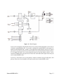
ACCES I/O PRODUCTS INC
10623 Roselle Street, San Diego, CA 92121
TEL (858)550-9559
FAX (858)550-7322
MODEL ROB-8A
USER MANUAL
FILE: MROB-8A.D1
Notice
The information in this document is provided for reference only. ACCES does not assume any liability
arising out of the application or use of the information or products described herein. This document may
contain or reference information and products protected by copyrights or patents and does not convey any
license under the patent rights of ACCES, nor the rights of others.
IBM PC, PC/XT, and PC/AT are registered trademarks of the International Business Machines Corporation.
Printed in USA. Copyright 2000 by ACCES I/O Products Inc, 10623 Roselle Street, San Diego, CA 92121.
All rights reserved.
Page iii
Warranty
Prior to shipment, ACCES equipment is thoroughly inspected and tested to applicable specifications.
However, should equipment failure occur, ACCES assures its customers that prompt service and support
will be available. All equipment originally manufactured by ACCES which is found to be defective will be
repaired or replaced subject to the following considerations.
Terms and Conditions
If a unit is suspected of failure, contact ACCES' Customer Service department. Be prepared to give the unit
model number, serial number, and a description of the failure symptom(s). We may suggest some simple
tests to confirm the failure. We will assign a Return Material Authorization (RMA) number which must
appear on the outer label of the return package. All units/components should be properly packed for handling
and returned with freight prepaid to the ACCES designated Service Center, and will be returned to the
customer's/user's site freight prepaid and invoiced.
Coverage
First Three Years: Returned unit/part will be repaired and/or replaced at ACCES option with no charge for
labor or parts not excluded by warranty. Warranty commences with equipment shipment.
Following Years: Throughout your equipment's lifetime, ACCES stands ready to provide on-site or in-plant
service at reasonable rates similar to those of other manufacturers in the industry.
Equipment Not Manufactured by ACCES
Equipment provided but not manufactured by ACCES is warranted and will be repaired according to the
terms and conditions of the respective equipment manufacturer's warranty.
General
Under this Warranty, liability of ACCES is limited to replacing, repairing or issuing credit (at ACCES
discretion) for any products which are proved to be defective during the warranty period. In no case is
ACCES liable for consequential or special damage arriving from use or misuse of our product. The
customer is responsible for all charges caused by modifications or additions to ACCES equipment not
approved in writing by ACCES or, if in ACCES opinion the equipment has been subjected to abnormal use.
"Abnormal use" for purposes of this warranty is defined as any use to which the equipment is exposed other
than that use specified or intended as evidenced by purchase or sales representation. Other than the above,
no other warranty, expressed or implied, shall apply to any and all such equipment furnished or sold by
ACCES.
Page iv
Table of Contents
Notice.. . . . . . . . . . . . . . . . . . . . . . . . . . . . . . . . . . . . . . . . . . . . . . . . . . . . . . . . . . . . . .
Warranty. . . . . . . . . . . . . . . . . . . . . . . . . . . . . . . . . . . . . . . . . . . . . . . . . . . . . . . . . . . .
FOREWORD. . . . . . . . . . . . . . . . . . . . . . . . . . . . . . . . . . . . . . . . . . . . . . . . . . . . . . . . .
Guarantee. . . . . . . . . . . . . . . . . . . . . . . . . . . . . . . . . . . . . . . . . . . . . . . . . . . . . . . . . . .
Limited Warranty. . . . . . . . . . . . . . . . . . . . . . . . . . . . . . . . . . . . . . . . . . . . . . . . . . . . .
Return Procedure. . . . . . . . . . . . . . . . . . . . . . . . . . . . . . . . . . . . . . . . . . . . . . . . . . . . .
Limitation of Liability. . . . . . . . . . . . . . . . . . . . . . . . . . . . . . . . . . . . . . . . . . . . . . . . . .
Advisories. . . . . . . . . . . . . . . . . . . . . . . . . . . . . . . . . . . . . . . . . . . . . . . . . . . . . . . . . . .
iii
iv
iii
iv
iv
v
v
vi
Chapter 1: Introduction. . . . . . . . . . . . . . . . . . . . . . . . . . . . . . . . . . . . . . . . . . . . . . . 1-1
Specifications. . . . . . . . . . . . . . . . . . . . . . . . . . . . . . . . . . . . . . . . . . . . . . . . . . . . . . . . . . 1-2
Chapter 2: Installation . . . . . . . . . . . . . . . . . . . . . . . . . . . . . . . . . . . . . . . . . . . . . . . 2-1
CD Installation.. . . . . . . . . . . . . . . . . . . . . . . . . . . . . . . . . . . . . . . . . . . . . . . . . . . . . . . . .
3.5-Inch Diskette Installation. . . . . . . . . . . . . . . . . . . . . . . . . . . . . . . . . . . . . . . . . . . . . . .
Directories Created on the Hard Disk. . . . . . . . . . . . . . . . . . . . . . . . . . . . . . . . . . . . . . . .
Installing the ROB-8A. . . . . . . . . . . . . . . . . . . . . . . . . . . . . . . . . . . . . . . . . . . . . . . . . . . .
2-1
2-1
2-2
2-4
Chapter 3: Connector Pin Assignments. . . . . . . . . . . . . . . . . . . . . . . . . . . . . . . . . 3-1
Appendix A: Demonstration Program. . . . . . . . . . . . . . . . . . . . . . . . . . . . . . . . . . A-1
Page v
List of Figures
Figure 1-1: Block Diagram. . . . . . . . . . . . . . . . . . . . . . . . . . . . . . . . . . . . . . . . . . . . . . . . . . . 1-3
Figure 2-1: ROB-8A Layout. . . . . . . . . . . . . . . . . . . . . . . . . . . . . . . . . . . . . . . . . . . . . . . . . . 2-6
List of Tables
Table 3-1: Connector Pin Assignments. . . . . . . . . . . . . . . . . . . . . . . . . . . . . . . . . . . . . . . . . 3-1
Table 3-2: External Power Connections . . . . . . . . . . . . . . . . . . . . . . . . . . . . . . . . . . . . . . . . 3-2
Page vi
Chapter 1: Introduction
ROB-8A is an eight-channel electromechanical relay output accessory card that accepts inputs from
parallel digital I/O cards. As many as four ROB-8As can be connected to one 24-bit I/O port.
Provide +5 VDC from an external power supply via screw terminals at TB9 or from the computer’s
hard disk drive power cable Molex connector.
The card can receive inputs from Port A of any 24-bit group of any ACCES digital I/O card via a
CAB50F-xx ribbon cable. A read-back capability is provided for Port B of that same 24-bit group.
The lower nybble Port C bits PC0 and PC1 are used for card address decoding when multiple
ROB-8As are used and Port C high nybble bits are coupled to screw terminals (TB10) on the card
for general purpose use.
ROB-8A contains eight Form C relays (SPDT). Dual Form C relays (DPDT) are an optional
configuration. Relay connections are brought out to eight sets of labeled screw terminals. Two
LEDs, one green and one red, are associated with each relay. The green LED is illuminated when
the relay is de-energized and the red LED glows when the relay is energized. A Polarity Select
switch on the card provides means to energize the relays from either high or low logic levels.
The relays used are UL-recognized, non-latching, polarized units designed to FCC Part 68 isolation
requirements and can switch up to two amperes current into a resistive load.
Manual MROB-8A.D1
Page 1-1
ROB-8A Manual
Specifications
Logic Inputs (8 Lines)
•
•
•
•
Logic High:
Logic Low:
Input Load (Hi):
Input Load (Lo):
2.0 to 5.0 VDC
-0.5 to 0.8 VDC
70 microamperes
600 microamperes
Logic Outputs (4 Lines)
•
•
Logic High:
Logic Low:
2.5 VDC min., load drive depends on signal source
0.5 VDC max., load drive depends on signal source
Relay Outputs
•
•
•
•
•
•
•
•
•
•
Contacts:
Form C, SPDT, non-latching (DPDT optional)
Contact Material:
Gold overlay silver
Contact Rating:
28 V DC at 1 A; 120 V AC at 0.5 A
Max. Switched Current:
2 A DC or 1.25 A AC
Max. Carry Current:
2 A, AC or DC
Max. Switched Voltage:
125V DC or 220 V AC
Max. Switched Power:
30 VA DC or 60 VA AC (resistive)
Operate Time @ nominal voltage:
8 milliseconds max. (including bounce)
Release Time @ nominal voltage:
8 milliseconds max.
Life Expectancy:
2 x 10⁷ operations at 18,000 ops/hr.
•
Power Required:
•
Size:
+5 VDC at 0.15A (all relays OFF) and 0.9A (all relays ON) each
ROB-8A.
4.5" x 6.125" (114 mm x 156 mm)
Environmental
•
•
•
Operating Temperature Range: 0 EC. to 60 EC.
Storage Temperature Range:
-30 EC. to 105 EC.
Humidity:
45% to 90% RH, non-condensing
Page 1-2
Manual MROB-8A.D1
Figure 1-1: Block Diagram
If your card is configured with optional sockets for easy removal and replacement of your relays, it
is marked as model ROB-8A-S01. If your card is configured for optional DPDT relay outputs, it is
marked as model ROB-8A-S02. Further, if your application requires that the relays be in a known
state at power-up, pull-up or pull-down resistors may have been specified when the card was ordered.
If, for example, all relays are to be de-actuated at power up and the polarity switch is set for
actuation on HIGH inputs, then pull-down resistors have been added at the input circuits and your
card is marked ROB-8A-S04.
Conversely, if the intent was to set the polarity switch for actuation on logic LOW inputs, then
pull-up resistors have been installed at the inputs and the unit is marked ROB-8A-S03.
Manual MROB-8A.D1
Page 1-3
ROB-8A Manual
Page 1-4
Manual MROB-8A.D1
Chapter 2: Installation
The software provided with this card is contained on either one CD or multiple diskettes and must
be installed onto your hard disk prior to use. To do this, perform the following steps as appropriate
for your software format and operating system. Substitute the appropriate drive letter for your
CD-ROM or disk drive where you see d: or a: respectively in the examples below.
CD Installation
DOS/WIN3.x
1.
2.
3.
4.
Place the CD into your CD-ROM drive.
Type d:K to change the active drive to the CD-ROM drive.
Type installK to run the install program.
Follow the on-screen prompts to install the software for this card.
WIN95/98/NT/2000
A.
B.
C.
Place the CD into your CD-ROM drive.
The CD should automatically run the install program after 30 seconds. If the install program
does not run, click START | RUN and type d:install, click OK or press K.
Follow the on-screen prompts to install the software for this card.
3.5-Inch Diskette Installation
As with any software package, you should make backup copies for everyday use and store your
original master diskettes in a safe location. The easiest way to make a backup copy is to use the DOS
DISKCOPY utility.
In a single-drive system, the command is:
diskcopy a: a:K
You will need to swap disks as requested by the system.
In a two-disk system, the command is:
diskcopy a: b:K
This will copy the contents of the master disk in drive A to the backup disk in drive B.
Manual MROB-8A.D1
Page 2-1
ROB-8A Manual
To copy the files on the master diskette to your hard disk, perform the following steps.
a.
Place the master diskette into a floppy drive.
b.
Change the active drive to the drive that has the diskette installed. For example, if the
diskette is in drive A, type a:K.
c.
Type installK and follow the on-screen prompts.
Directories Created on the Hard Disk
The installation process will create several directories on your hard disk. If you accept the
installation defaults, the following structure will exist.
[CARDNAME]
Root or base directory containing the SETUP.EXE setup program used to help you configure
jumpers and calibrate the card.
DOS\PSAMPLES:
DOS\CSAMPLES:
Win32\language:
A subdirectory of [CARDNAME] that contains Pascal samples.
A subdirectory of [CARDNAME] that contains "C" samples.
Subdirectories containing samples for Win95/98 and NT.
WinRISC.exe
A Windows dumb-terminal type communication program designed for RS422/485 operation.
Used primarily with Remote Data Acquisition Pods and our RS422/485 serial communication
product line. Can be used to say hello to an installed modem.
ACCES32
This directory contains the Windows 95/98/NT driver used to provide access to the hardware
registers when writing 32-bit Windows software. Several samples are provided in a variety of
languages to demonstrate how to use this driver. The DLL provides four functions (InPortB,
OutPortB, InPort, and OutPort) to access the hardware.
This directory also contains the device driver for Windows NT, ACCESNT.SYS. This device driver
provides register-level hardware access in Windows NT. Two methods of using the driver are
available, through ACCES32.DLL (recommended) and through the DeviceIOControl handles
provided by ACCESNT.SYS (slightly faster).
Page 2-2
Manual MROB-8A.D1
SAMPLES
Samples for using ACCES32.DLL are provided in this directory. Using this DLL not only
makes the hardware programming easier (MUCH easier), but also one source file can be used
for both Windows 95/98 and WindowsNT. One executable can run under both operating
systems and still have full access to the hardware registers. The DLL is used exactly like any
other DLL, so it is compatible with any language capable of using 32-bit DLLs. Consult the
manuals provided with your language's compiler for information on using DLLs in your specific
environment.
VBACCES
This directory contains sixteen-bit DLL drivers for use with VisualBASIC 3.0 and Windows 3.1
only. These drivers provide four functions, similar to the ACCES32.DLL. However, this DLL is
only compatible with 16-bit executables. Migration from 16-bit to 32-bit is simplified because of
the similarity between VBACCES and ACCES32.
PCI
This directory contains PCI-bus specific programs and information. If you are not using a PCI card,
this directory will not be installed.
SOURCE
A utility program is provided with source code you can use to determine allocated resources at
run-time from your own programs in DOS.
PCIFind.exe
A utility for DOS and Windows to determine what base addresses and IRQs are allocated to
installed PCI cards. This program runs two versions, depending on the operating system. Windows
95/98/NT displays a GUI interface, and modifies the registry. When run from DOS or Windows3.x,
a text interface is used. For information about the format of the registry key, consult the
card-specific samples provided with the hardware. In Windows NT, NTioPCI.SYS runs each time
the computer is booted, thereby refreshing the registry as PCI hardware is added or removed. In
Windows 95/98/NT PCIFind.EXE places itself in the boot-sequence of the OS to refresh the registry
on each power-up.
This program also provides some COM configuration when used with PCI COM ports. Specifically,
it will configure compatible COM cards for IRQ sharing and multiple port issues.
WIN32IRQ
This directory provides a generic interface for IRQ handling in Windows 95/98/NT. Source code
is provided for the driver, greatly simplifying the creation of custom drivers for specific needs.
Samples are provided to demonstrate the use of the generic driver. Note that the use of IRQs in
near-real-time data acquisition programs requires multi-threaded application programming
techniques and must be considered an intermediate to advanced programming topic. Delphi, C++
Builder, and Visual C++ samples are provided.
Manual MROB-8A.D1
Page 2-3
ROB-8A Manual
Findbase.exe
DOS utility to determine an available base address for ISA bus , non-Plug-n-Play cards. Run this
program once, before the hardware is installed in the computer, to determine an available address
to give the card. Once the address has been determined, run the setup program provided with the
hardware to see instructions on setting the address switch and various option selections.
Poly.exe
A generic utility to convert a table of data into an nth order polynomial. Useful for calculating
linearization polynomial coefficients for thermocouples and other non-linear sensors.
Risc.bat
A batch file demonstrating the command line parameters of RISCTerm.exe.
RISCTerm.exe
A dumb-terminal type communication program designed for RS422/485 operation. Used primarily
with Remote Data Acquisition Pods and our RS422/485 serial communication product line. Can be
used to say hello to an installed modem. RISCTerm stands for Really Incredibly Simple
Communications TERMinal.
Installing the ROB-8A
The ROB-8A is installed external to the host computer. The card is supplied with four 0.375"
stand-offs and may be installed in either T-Box enclosures from ACCES or on user-supplied
panels/chassis. To install the card without the box in your own enclosure, see Figure 2-2 for the hole
spacing. ROB-8A provides two 50-pin headers for 50-conductor ribbon cable connection to the host
computer and to another ROB-8A when more than one ROB-8A is in use. Screw terminals are
provided for the relay outputs. The screw terminals used can accommodate wire sizes as large as #14
AWG. Silk-screen labels on the card identify the relay elements and other related functions. As you
read the following descriptions, refer to the layout drawing on the next page for the locations of
switches, jumpers, and terminal strips.
Page 2-4
Manual MROB-8A.D1
DIP switch S1 sets various modes of operation as follows:
Switches #1 through #4 set the card address in multiple ROB-8A applications.
Switch #5 must be set to ON for multiple card operation.
This switch is set to OFF when only one ROB-8A is to be used. (The card will respond to
requests from any of the four addresses.)
Card No.
Address
S1
S2
S3
S4
S5
1
0
ON
Off
Off
Off
ON
2
1
Off
ON
Off
Off
ON
3
2
Off
Off
ON
Off
ON
4
3
Off
Off
Off
ON
ON
Switch #6 is set ON if a logic 1 is to actuate the relays and set to OFF if a logic 0 is to actuate the
relays.
TB9's screw terminals (AWG 14 max size, AWG 16 minimum recommended size) or the Molex
quick connect are used for external +5 VDC power input to the ROB-8A.
Manual MROB-8A.D1
Page 2-5
ROB-8A Manual
Figure 2-1: ROB-8A Layout
Page 2-6
Manual MROB-8A.D1
Chapter 3: Connector Pin Assignments
A 50-pin ribbon cable header is used to interface to the digital output card in the host computer.
The mating connector is a type AMP 1-746285-0 or equivalent.
Pin
Assignment
Pin
Assignment
1
Bit PC7 to Screw Terminal
2
Ground
3
Bit PC6
"
"
4
"
5
Bit PC5
"
"
6
"
7
Bit PC4
"
"
8
"
9
Bit PC3 Unused
10
"
11
Bit PC2 Read/W rite
12
"
13
Bit PC1 Address Select
14
"
15
Bit PC0 Address Select
16
"
17
Bit PB7 Relay 7 Readback
18
"
19
Bit PB6 Relay 6
"
20
"
21
Bit PB5 Relay 5
"
22
"
23
Bit PB4 Relay 4
"
24
"
25
Bit PB3 Relay 3
"
26
"
27
Bit PB2 Relay 2
"
28
"
29
Bit PB1 Relay 1
"
30
"
31
Bit PB0 Relay 0
"
32
"
33
Bit PA7 to Relay 7
34
"
35
Bit PA6 to Relay 6
36
"
37
Bit PA5 to Relay 5
38
"
39
Bit PA4 to Relay 4
40
"
41
Bit PA3 to Relay 3
42
"
43
Bit PA2 to Relay 2
44
"
45
Bit PA1 to Relay 1
46
"
47
Bit PA0 to Relay 0
48
"
49
Not Connected
50
"
Table 3-1: Connector Pin Assignments
Manual MROB-8A.D1
Page 3-1
ROB-8A Manual
TB9
J3
Pin
Assignment
Pin
Assignment
1
+5VDC
1
Open
2
Gnd
2
Gnd
3
Gnd
4
+5VDC
Table 3-2: External Power Connections
Page 3-2
Manual MROB-8A.D1
Appendix A: Demonstration Program
The following program, written in BASIC, illustrates how easy it is to interface the ROB-8A to'
digital input/output cards. This example was written for the IOD-24E or IOD-24 but, with minor
variations could be used with any of the IOD-Series cards.
This program allows any relay to be turned on or off
This program expects an ACCES IOD-xx board to be connected' to a ROB-8A relay board, with the
base address of the IOD-xx ' card set to hex 300.
‘Set up the variables
DIM RELAYS%(8) ' mask for each relay
RELSTATE% = 255 ' start all HI which is off
RELAYS%(1) = 1 ' first relay mask
FOR I = 1 TO 7 ' set up the relay masks
RELAYS%(I + 1) = RELAYS%(I) * 2 ' shift prev one left
NEXT I
‘Now initialize the board
CWORD% = &H8A
WSTATE% = &H4
PORTA% = &H300
PORTC% = &H302
CADDR% = &H303
' port A and C-lo are OUT, others are IN
' Use board #1, write function
' port address, also port A
' port C
' address for control word
OUT CADDR%, CWORD% ' program the ports
OUT PORTC%, WSTATE% ' program port C for board number and write function
OUT PORTA%, RELSTATE% ' turn off all relays
‘Do menu selection here
MENU:
CLS
PRINT
PRINT
PRINT "
RELAY DEMONSTRATION PROGRAM"
PRINT "
COPYRIGHT ACCES"
PRINT
PRINT
PRINT "
1 Toggle any relay"
PRINT "
2 RUN a simple sequence"
PRINT "
3 Quit"
PRINT
PRINT "
ROB-8A must have ADDR0 and REVB ON for sample to work."
Manual MROB-8A.D1
Page A-1
ROB-8A Manual
PRINT "
All other switches must be off. The IOD-24(E) must be at"
PRINT "
base address 300 HEX."
PRINT
SELCT:
INPUT " Your selection"; PICK
PRINT ""
IF PICK >= 1 AND PICK <= 3 THEN GOTO CONT
PRINT " OUT OF RANGE, TRY AGAIN."
GOTO SELCT
CONT:
ON PICK GOSUB TOGGLE, SEQUENCE, QUIT
GOTO MENU
‘This section will toggle a relay
TOGGLE:
CLS
PRINT
PRINT
RETRY:
INPUT "Enter relay number to toggle:"; REL
IF REL >= 1 AND REL <= 8 THEN GOTO DOIT
PRINT "Invalid relay number, try again."
GOTO RETRY
DOIT:
TEMP% = NOT RELSTATE%
RELSTATE% = NOT (TEMP% XOR RELAYS%(REL))
OUT PORTA%, RELSTATE%
RETURN
WALKIT:
RELSTATE% = NOT (RELAYS%(REL))
OUT PORTA%, RELSTATE%
RETURN
SEQUENCE:
‘Performs a simple sequence by turning all relays off, then
‘turning them on, one by one, then turning them off one by one
RELSTATE% = 255
' turn off the relays
OUT PORTA%, RELSTATE%
FOR REL = 1 TO 8
GOSUB WALKIT ' turn on the relay
GOSUB DELAY
NEXT REL
Page A-2
Manual MROB-8A.D1
RELSTATE% = 0
OUT PORTA%, RELSTATE%
GOSUB DELAY
FOR REL = 8 TO 1 STEP -1
GOSUB DOIT ' turn off the relay
GOSUB DELAY ' one second delay
NEXT REL
RETURN
DELAY:
FOR OURDELAY = 1 TO 5000: NEXT
RETURN
QUIT:
‘Program exit
END
Manual MROB-8A.D1
Page A-3
ROB-8A Manual
Page A-4
Manual MROB-8A.D1
Customer Comments
If you experience any problems with this manual or just want to give us some feedback, please email
us at: [email protected].. Please detail any errors you find and include your mailing address
so that we can send you any manual updates.
10623 Roselle Street, San Diego CA 92121
Tel. (858)550-9559 FAX (858)550-7322
www.accesioproducts.com