1
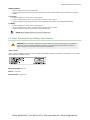
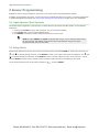
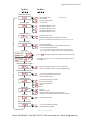
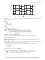
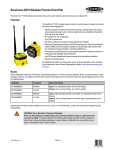
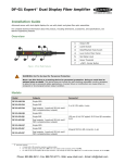
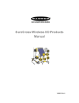
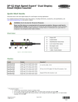
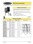
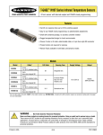
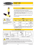
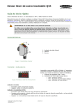
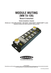
Q4X Stainless Steel Laser Sensor
Instruction Manual
Original Instructions
181483 Rev. E
9 March 2015
Phone: 800.894.0412 - Fax: 888.723.4773 - Web: www.clrwtr.com - Email: [email protected]
Q4X Stainless Steel Laser Sensor
Contents
1 Product Description
........................................................................................................ 3
....................................................................................................................................3
1.1 Models
1.2 Overview
................................................................................................................................ 3
1.3 Features
................................................................................................................................. 4
1.3.1 Display and Indicators
......................................................................................................4
1.3.2 Buttons
......................................................................................................................... 4
1.4 Laser Description and Safety Information
.................................................................................... 5
2 Installation
2.1
2.2
2.3
2.4
2.5
..................................................................................................................... 6
Install the Safety Label
............................................................................................................. 6
Sensor Orientation
................................................................................................................... 6
Sensor Mounting
...................................................................................................................... 7
Wiring Diagram
........................................................................................................................7
Cleaning and Maintenance
.........................................................................................................7
3 Sensor Programming
..................................................................................................... 8
3.1 Light Operate/Dark Operate
...................................................................................................... 8
3.2 Setup Mode
.............................................................................................................................8
3.2.1 TEACH Menu
................................................................................................................ 10
3.2.2 Response Speed
........................................................................................................... 10
3.2.3 Output Timing Delays
....................................................................................................10
3.2.4 Zero Reference Location
................................................................................................ 11
3.2.5 Shift the Zero Reference Location after a TEACH
............................................................... 12
3.2.6 Input Wire Function
...................................................................................................... 12
3.2.7 Display View
................................................................................................................ 12
3.2.8 Exit Setup Mode
........................................................................................................... 12
3.2.9 Reset to Factory Defaults
...............................................................................................12
3.3 Manual Adjustments
............................................................................................................... 13
3.4 Remote Input
......................................................................................................................... 13
3.4.1 Select the TEACH Mode Using the Remote Input
............................................................... 14
3.4.2 Reset to Factory Defaults Using the Remote Input
.............................................................15
3.5 Locking and Unlocking the Sensor Buttons
.................................................................................. 15
3.6 TEACH Procedures
.................................................................................................................. 15
3.6.1 Two-Point Static Background Suppression TEACH
..............................................................15
3.6.2 Dynamic Background Suppression TEACH
........................................................................ 17
3.6.3 One-Point Window (Foreground Suppression)
................................................................... 18
3.6.4 One-Point Background Suppression
................................................................................. 20
3.7 Sync Master/Slave
..................................................................................................................21
4 Specifications
.............................................................................................................. 22
4.1 Dimensions
........................................................................................................................... 23
4.2 Performance Curves
............................................................................................................... 23
5 Abbreviations
.............................................................................................................. 24
6 Troubleshooting
...........................................................................................................26
7 Accessories
...................................................................................................................27
7.1 Cordsets
............................................................................................................................... 27
7.2 Brackets
............................................................................................................................... 28
7.3 Aperture Kits
......................................................................................................................... 28
8 Contact Us
................................................................................................................... 29
9 Banner Engineering Corp Limited Warranty
................................................................. 30
Phone: 800.894.0412 - Fax: 888.723.4773 - Web: www.clrwtr.com - Email: [email protected]
Q4X Stainless Steel Laser Sensor
1 Product Description
Class 1 laser CMOS sensor with a bipolar (1 PNP & 1 NPN) output. Patent pending.
•
•
•
•
•
•
•
•
•
•
The ultimate problem solver: reduce sensor inventory with a reliable, durable
sensor that solves the most challenging applications
Solves difficult distance‐based applications regardless of target surface reflectivity,
including black foam on black plastic, black rubber in front of metal, multicolor
packaging and targets of all colors
Reliable sensing range of 25 mm (0.98 in) to 300 mm (11.81 in) with best in class
excess gain
Angled four‐digit display with submillimeter resolution is easily viewed from
multiple vantage points
Display provides clear user feedback for easy setup, and bright output indicator
provides high visibility of sensor operation
Intuitive setup utilizing three tactile buttons conveniently located below the display
Durable and robust construction resists mechanical impact, over tightening and
extreme vibration
FDA grade stainless steel, chemically‐resistant material and laser marked sensor
information withstands aggressive cleaning procedures
Superior resistance to ambient light interference prevents nuisance output trips
under changing lighting conditions
Temperature-compensated design ensures reliable detection during changing
temperature conditions
WARNING: Not To Be Used for Personnel Protection
Never use this device as a sensing device for personnel protection. Doing so could lead to
serious injury or death. This device does not include the self-checking redundant circuitry necessary
to allow its use in personnel safety applications. A sensor failure or malfunction can cause either an
energized or de-energized sensor output condition.
1.1 Models
Model
Sensing Range
Output
Cable
Q4XTBLAF300-Q8
25 mm (0.98 in) to 300 mm (11.81 in)
Bipolar: 1 NPN; 1 PNP
5-pin Euro M12 Integral Connector
1.2 Overview
The Q4X Sensor is a Class 1 laser CMOS sensor with a bipolar output. The normal sensor state is Run mode. From Run
mode, the switch point value and LO/DO selection can be changed and the selected TEACH method can be performed. The
secondary sensor state is Setup mode. From Setup mode, the TEACH mode can be selected, all standard operating
parameters can be adjusted, and a factory reset can be done.
Phone: 800.894.0412 - Fax: 888.723.4773 - Web: www.clrwtr.com - Email: [email protected]
Q4X Stainless Steel Laser Sensor
1.3 Features
1
2
3
1. Output Indicator (Amber)
2. Display
3. Buttons
Figure 1. Sensor Features
1.3.1 Display and Indicators
1
2
Figure 2. Display in Run Mode
The display is a 4-digit, 7-segment LED. The main screen is
the Run Mode screen, which shows the current distance to
the target in millimeters.
1. Stability Indicator (STB = Green)
2. Active TEACH Indicators
• DYN = Dynamic (Amber)
• FGS = Foreground Suppression (Amber)
• BGS = Background Suppression (Amber)
Output Indicator
•
•
On—Outputs conducting (closed)
Off—Outputs not conducting (open)
Stability Indicator (STB)
•
•
•
On—Stable signal within the specified sensing range
Flashing—Marginal signal, the target is outside the limits of the specified sensing range, or a multiple peak
condition exists
Off—No target detected within the specified sensing range
Active TEACH Indicators (DYN, FGS, and BGS)
•
•
•
•
DYN, FGS, and BGS all off = Two-point TEACH mode selected (default)
DYN on = Dynamic TEACH mode selected
FGS on = Foreground suppression TEACH mode selected
BGS on = Background suppression TEACH mode selected
1.3.2 Buttons
Use the sensor buttons (SELECT)(TEACH), (+)(LO/DO), and (-)(MODE) to program the sensor.
Phone: 800.894.0412 - Fax: 888.723.4773 - Web: www.clrwtr.com - Email: [email protected]
Q4X Stainless Steel Laser Sensor
(SELECT)(TEACH)
• Press to select menu items in Setup mode
• Press and hold for longer than 2 seconds to start the currently selected TEACH mode (the default is two-point
TEACH)
(+)(LO/DO)
• Press to navigate the sensor menu in Setup mode
• Press to change setting values; press and hold to increase numeric values
• Press and hold for longer than 2 seconds to switch between light operate (LO) and dark operate (DO)
(-)(MODE)
• Press to navigate the sensor menu in Setup mode
• Press to change setting values; press and hold to decrease numeric values
• Press and hold for longer than 2 seconds to enter Setup mode
NOTE: When navigating the menu, the menu items loop.
1.4 Laser Description and Safety Information
CAUTION: Use of controls or adjustments or performance of procedures other than those specified
herein may result in hazardous radiation exposure. Do not attempt to disassemble this sensor for
repair. A defective unit must be returned to the manufacturer.
Class 1 Lasers
Class 1 lasers are lasers that are safe under reasonably foreseeable conditions of operation, including the use of optical
instruments for intrabeam viewing.
Laser wavelength: 655 nm
Output: < 0.20 mW
Pulse Duration: 7 µs to 2 ms
Phone: 800.894.0412 - Fax: 888.723.4773 - Web: www.clrwtr.com - Email: [email protected]
Q4X Stainless Steel Laser Sensor
2 Installation
CLASS 1
LASER PRODUCT
The safety label must be installed on Q4X sensors that are used in the
United States.
NOTE: Position the label on the cable in a location that
has minimal chemical exposure.
1. Remove the protective cover from the adhesive on the label.
2. Wrap the label around the Q4X cable, as shown.
3. Press the two halves of the label together.
COMPLIES WITH IEC 60825-1:2007
2.1 Install the Safety Label
COMPLIES WITH 21 CFR 1040.10 AND 1040.11
EXCEPT FOR DEVIATIONS PURSUANT TO
LASER NOTICE No. 50, DATED JUNE 24, 2007.
BANNER ENGINEERING CORP.
9714 10TH AVENUE NORTH
MINNEAPOLIS, MN 55441
CLASS 1
LASER PRODUCT
COMPLIES WITH IEC 60825-1:2007
Figure 3. Safety Label Installation
2.2 Sensor Orientation
Optimize detection reliability and minimum object separation performance with correct sensor-to-target orientation. To
ensure reliable detection, orient the sensor as shown in relation to the target to be detected.
Figure 4. Optimal Orientation of Target to Sensor
See the following figures for examples of correct and incorrect sensor-to-target orientation as certain placements may
pose problems for sensing some targets. The Q4X can be used in the less preferred orientation and provide reliable
detection performance; see Figure 16 on page 23 for the minimum object separation distance required for each case.
Correct
Incorrect
Figure 5. Orientation by a wall
Correct
Incorrect
Figure 6. Orientation for a turning object
(Optimal)
Correct
Incorrect
Figure 7. Orientation for a height difference
Horizontal
Orientation
Vertical
Orientation
Figure 8. Orientation for a color or luster difference
Phone: 800.894.0412 - Fax: 888.723.4773 - Web: www.clrwtr.com - Email: [email protected]
Q4X Stainless Steel Laser Sensor
2.3 Sensor Mounting
1. If a bracket is needed, mount the sensor onto the bracket.
2. Mount the sensor (or the sensor and the bracket) to the machine or equipment at the desired location. Do not
tighten at this time.
3. Check the sensor alignment.
4. Tighten the screws to secure the sensor (or the sensor and the bracket) in the aligned position.
2.4 Wiring Diagram
1
+
10-30V dc
–
3
2
4
5
1
2
4
5
3
Load
Load
Key
Remote
Teach
NOTE: Open lead wires must be connected to a terminal block.
1
2
3
4
5
=
=
=
=
=
Brown
White
Blue
Black
Gray
NOTE: The input wire function is user-selectable. The default for the input wire function is off
(disabled).
2.5 Cleaning and Maintenance
Handle the sensor with care during installation and operation. Sensor windows soiled by fingerprints, dust, water, oil, etc.
may create stray light that may degrade the peak performance of the sensor. Blow the window clear using filtered,
compressed air, then clean as necessary using water and a lint-free cloth.
Phone: 800.894.0412 - Fax: 888.723.4773 - Web: www.clrwtr.com - Email: [email protected]
Q4X Stainless Steel Laser Sensor
3 Sensor Programming
Program the sensor using the buttons on the sensor or the remote input (limited programming options).
In addition to programming the sensor, use the remote input to disable the buttons for security, preventing unauthorized
or accidental programming changes. See Locking and Unlocking the Sensor Buttons on page 15 for more information.
3.1 Light Operate/Dark Operate
The default output configuration is light operate. To switch between light operate and dark operate, use the following
instructions:
1. Press and hold LO/DO for longer than 2 seconds. The current selection displays.
2. Press LO/DO again. The new selection flashes slowly.
3. Press SELECT to change the output configuration and return to Run mode.
NOTE: If neither SELECT nor LO/DO are pressed after step 2, the new selection flashes slowly
for a few seconds, then flashes quickly and the sensor automatically changes the output
configuration and returns to Run mode.
3.2 Setup Mode
Access Setup mode and the sensor menu from Run mode by pressing and holding MODE for longer than 2 seconds. Use
and
to navigate through the menu. Press SELECT to select a menu option and access the submenus. Use
and
to navigate through the submenus. Press SELECT to select a submenu option and return to the top menu, or press
and hold SELECT for longer than 2 seconds to select a submenu option and return immediately to Run mode.
To exit Setup mode and return to Run mode, navigate to
and press SELECT.
Phone: 800.894.0412 - Fax: 888.723.4773 - Web: www.clrwtr.com - Email: [email protected]
Q4X Stainless Steel Laser Sensor
Top Menu
Sub Menus
Teach Process Selection
Response Speed
Gain and Sensitivity*
two-point static BGS
dynamic BGS
one-point Window (FGS)
one-point BGS
(
default setting)
set Response Speed to 1.5 ms
set Response Speed to 3 ms
set Response Speed to 10 ms
set Response Speed to 25 ms
set Response Speed to 50 ms
high excess gain mode
standard excess gain with increased noise immunity
Gain menu is available when Response Speed is set to 10, 25 or 50 ms
Output Timing Delays
off: no delays enabled
enable on and/or off delay (set value in Delay Timer menu)
1 Shot, fixed output pulse duration
LO = On pulse when a target is detected inside of the switch point(s)
DO = On pulse when a target is detected outside of the switch point(s)
Delay Timer
Available when
selected
ms to
Available when
selected
when
is selected,1 to 9 ms is range available when Response Speed is
set to 1.5 or 3 ms
sec range, set Delay Timer value (seconds have decimal)
Select Zero Reference Location
near: set zero displayed value to end of 18 mm barrel
far: set zero displayed value to maximum detection range
Shift Zero Reference after Teach
Input Wire Function
Display Read
Exit Setup
on: move the zero point after each teach
off: zero point is either at end of barrel or
maximum detection range
off: remote teach input is not active
set: Remote Teach input
laser off when pulled low
master
slave
display on
display on, inverted
display off (enters sleep mode after 60 seconds)
display off, inverted (enters sleep mode after 60 seconds)
end: select to exit setup
Reset to Factory Defaults
no: do not reset to factory defaults
yes: reset to factory defaults
Figure 9. Sensor Menu Map
Phone: 800.894.0412 - Fax: 888.723.4773 - Web: www.clrwtr.com - Email: [email protected]
Q4X Stainless Steel Laser Sensor
3.2.1 TEACH Menu
Use this menu to select the TEACH mode. The default is two-point TEACH.
•
—Two-point static background suppression
•
—Dynamic background suppression
•
—One-point window (foreground suppression)
•
—One-point background suppression
After the TEACH mode is selected, from Run mode, press and hold TEACH for longer than 2 seconds to start the TEACH
mode and program the sensor. See TEACH Procedures on page 15 for additional information and remote input TEACH
instructions.
3.2.2 Response Speed
Use this menu to select the response speed. The default is 10 milliseconds.
•
—1.5 milliseconds
•
—3 milliseconds
•
—10 milliseconds
•
—25 milliseconds
•
—50 milliseconds
Table 1: Tradeoffs
Response Speed
Response Speed in
Sync Mode
Repeatability
Ambient Light
Rejection
1.5 ms
3 ms
500 µs
Disabled
3 ms
6 ms
500 µs
Enabled
10 ms
20 ms
2 ms
Enabled
25 ms
50 ms
5 ms
Enabled
50 ms
100 ms
10 ms
Enabled
Excess Gain
See Table 7 on page 22
Gain and Sensitivity
Use this menu to set the excess gain mode. This menu is only available when a 10, 25, or 50 millisecond response speed is
selected. It is not available for 1.5 or 3 millisecond response speeds.
•
—High excess gain mode
•
—Standard excess gain mode with increased noise immunity
3.2.3 Output Timing Delays
Use this menu to select the output timing delay to be set. On and off delay timers can be used together. The default is no
delay.
•
—No delay
•
—Delay—enables the selection of on and off delay timers
•
—One-shot—enables a one-shot, fixed output pulse duration
Phone: 800.894.0412 - Fax: 888.723.4773 - Web: www.clrwtr.com - Email: [email protected]
Q4X Stainless Steel Laser Sensor
ON
Output
OFF
D
OFF Delay
D
ON Delay
D
D
1-Shot
D
D
Time
(D = 1 - 9999 ms)
Figure 10. Output Timing Delays
When either
set the timer(s):
or
is chosen, the sensor returns to the Setup menu and additional options become available to
•
—On delay
•
—Off delay
•
—One-shot delay timer
NOTE: For the one-shot delay timer:
• LO = On pulse when a target is detected inside of the switch point(s)
• DO = On pulse when a target is detected outside of the switch point(s)
Delay Timers
,
,
Use these menus to set the delay timers. These menus are available only if an output timing delay is selected.
For
and
, the default is 0.
For
, the default is 10 milliseconds for 10, 25, and 50 millisecond response speeds and 1 millisecond for 1.5 and 3
milliseconds response speeds.
Use
and
to scroll through the values. Values greater than 10 increase or decrease by increments of 10. Millisecond
values do not include the decimal point; seconds values include the decimal point.
•
•
•
•
1 to 9 ms (when
10 to 90 ms
100 to 900 ms
1.0 to 90.0 s
is selected, the 1 to 9 ms range is available for 1.5 and 3 ms response times)
3.2.4 Zero Reference Location
Use this menu to select the zero reference location. The default is
, 0 = the end of the sensor barrel.
•
—0 = the end of the sensor barrel; the measurement increases further from the sensor
•
—0 = maximum range; the measurement increases closer to the sensor
Phone: 800.894.0412 - Fax: 888.723.4773 - Web: www.clrwtr.com - Email: [email protected]
Q4X Stainless Steel Laser Sensor
3.2.5 Shift the Zero Reference Location after a TEACH
Use this menu to select whether the sensor shifts the zero reference location to the last taught distance. The default is
, 0 = the end of barrel or the maximum range.
•
—Shift the zero reference location to one of the taught positions with each TEACH
•
—0 = the end of barrel or the maximum range, depending on the
setting
3.2.6 Input Wire Function
Use this menu to select the input wire function. The default is off, ignore all remote input pulses.
•
—Ignore all remote input pulses
•
—Remote TEACH input
•
—Laser off when pulled low
•
—Master sync line output for two-sensor cross-talk avoidance
•
—Slave sync line input for two-sensor cross-talk avoidance
To configure sensors for master-slave operation, see Sync Master/Slave on page 21.
3.2.7 Display View
Use this menu to select the display view. The default is right-reading.
•
—Right-reading
•
—Inverted
•
—Right-reading and the display enters sleep mode after 60 seconds
•
—Inverted and the display enters sleep mode after 60 seconds
When the sensor is in sleep mode, the display wakes with the first button press.
3.2.8 Exit Setup Mode
Navigate to
and press SELECT to exit Setup mode and return to Run mode.
3.2.9 Reset to Factory Defaults
Use this menu to restore the sensor to the factory default settings. See Factory Default Settings on page 12.
Select
to return to the sensor menu without restoring the defaults. Select
return to Run mode.
to apply the factory defaults and
Factory Default Settings
Setting
Display view (
Factory Default
)
Gain and sensitivity (
Input wire function (
—Right-reading, no sleep mode
)
)
—High excess gain mode
—Ignore all remote input pulses
If the sensor was reset using the remote input, the sensor
remains in
Output configuration
mode to allow use of the remote input.
LO—Light Operate
Phone: 800.894.0412 - Fax: 888.723.4773 - Web: www.clrwtr.com - Email: [email protected]
Q4X Stainless Steel Laser Sensor
Setting
Factory Default
Output timing delays (
Response speed (
)
—No delay
10 ms
)
Shift the Zero Reference Location after a TEACH (
TEACH process selection (
Zero reference location (
)
)
—0 = the end of barrel
—Two-point TEACH
)
—Measurement increases further from sensor
3.3 Manual Adjustments
Manually adjust the sensor switch point using the
1. From Run mode, press either
or
and
buttons.
one time. The current switch point value flashes slowly.
to move the switch point up or
to move the switch point down. After 1 second of inactivity, the new
2. Press
switch point value flashes rapidly, the new setting is accepted, and the sensor returns to Run mode.
NOTE: When FGS mode is selected (the FGS indicator is on), manual adjustment moves both sides of
the symmetrical threshold window simultaneously, expanding and collapsing the window size. Manual
adjustment does not move the center point of the window.
3.4 Remote Input
Use the remote input to program the sensor remotely. The remote input provides limited programming options and is
Active Low. For Active Low, connect the gray input wire to ground (0 V dc), with a remote switch connected between the
wire and ground. Pulse the remote input according to the diagram and the instructions provided in this manual.
The length of the individual programming pulses is equal to the value T: 0.04 seconds ≤ T ≤ 0.8 seconds.
Exit remote programming modes by setting the remote input low for longer than 2 seconds.
Phone: 800.894.0412 - Fax: 888.723.4773 - Web: www.clrwtr.com - Email: [email protected]
Q4X Stainless Steel Laser Sensor
Remote
Input
Input = Set
Gray wire is remote teach input
Pulse Timing (T)
0.04 seconds < T < 0.8 seconds
Timing between Pulse groups > 1 second
Starts selected Teach (same function as pressing Teach Button for > 2 sec)
1x
Second pulse completes Teach (Two-point and Dynamic Teach only)
1x
Teach Selection
2x
3x
Two-point static background suppression
Dynamic background suppression
One-point window (foreground suppression)
4x
One-point background suppression
1x
2x
Button Lock
4x
1x
Button Unlock (uloc)
2x
Button Lock (loc)
Reset to Factory Defaults (maintain remote input = SET)
8x
Figure 11. Remote Input Map
3.4.1 Select the TEACH Mode Using the Remote Input
1. Access the TEACH selection.
Action
Result
T
Double-pulse the remote input.
T
displays.
T
2. Select the desired TEACH mode.
Action
Result
Pulses
1
2
3
4
TEACH Mode
T
Two-point static background
suppression
T
T
Dynamic background suppression
T
T
T
T
T
T
T
T
One-point window (foreground
suppression)
T
T
T
T
T
The selected TEACH method displays for a
few seconds and the sensor returns to Run
mode.
One-point background suppression
Phone: 800.894.0412 - Fax: 888.723.4773 - Web: www.clrwtr.com - Email: [email protected]
Q4X Stainless Steel Laser Sensor
3.4.2 Reset to Factory Defaults Using the Remote Input
Eight-pulse the remote input to apply the factory defaults and return to Run mode.
T
T
T
T
T
T
T
T
T
T
T
T
T
T
T
NOTE: The input wire function remains at remote teach input (
).
3.5 Locking and Unlocking the Sensor Buttons
Use the lock and unlock feature to prevent unauthorized or accidental programming changes. When locked,
displays when the (SELECT)(TEACH) button is pressed. The switch point displays when (+)(LO/DO) or (-)(MODE) are
pressed, but
displays if the buttons are pressed and held.
Button Instructions
To lock or unlock the sensor using the buttons, press and hold
depending on the previous status.
and press
four times.
or
flashes,
Remote Input Instructions
1. Access the remote input.
Action
Result
Four-pulse the remote input.
T
T
T
T
T
T
T
The sensor is ready to have the button
state defined and
displays.
2. Lock or unlock the sensor buttons.
Action
Result
Single-pulse the remote input to unlock the sensor.
Double-pulse the remote input to lock the sensor.
T
displays and the sensor returns to
Run mode.
T
T
T
displays and the sensor returns to
Run mode.
3.6 TEACH Procedures
Use the following procedures to teach the sensor.
To cancel a TEACH procedure, press TEACH for longer than 2 seconds, or hold the remote input low for longer than 2
seconds.
momentarily displays when a TEACH procedure is canceled.
3.6.1 Two-Point Static Background Suppression TEACH
Two-point TEACH sets a single switch point. The sensor sets the switch point between two taught target distances, relative
to the shifted origin location.
Phone: 800.894.0412 - Fax: 888.723.4773 - Web: www.clrwtr.com - Email: [email protected]
Q4X Stainless Steel Laser Sensor
5
3
2
Press and Hold
> 2s
Press again
Press again
Switch
Point
Value
1
4
Figure 12. Two-Point Static Background Suppression (Light Operate shown)
NOTE: The sensor must be set to
=
to use the following instructions.
NOTE: To program the sensor using remote input, remote input must be enabled (
=
).
1. Present the target.
Method
Action
Result
Push Button
Present the first target. The sensor-to-target distance must be within
the sensor's range.
The target's measurement value
displays.
Remote Input
2. Start the TEACH mode.
Method
Action
Result
Push Button
Press and hold TEACH for longer than 2 seconds.
and
flash alternately
on the display. The DYN, FGS, and
BGS indicators flash.
Remote Input
No action required.
N/A
3. Teach the sensor.
Method
Action
Result
Push Button
Press TEACH to teach the target.
The sensor is taught the first target.
Remote Input
Single-pulse the remote input.
T
,
, and the current
distance measurement flash
alternately on the display. The DYN,
FGS, and BGS indicators flash.
4. Present the target.
Method
Action
Result
Present the second target. The sensor-to-target distance must be
within the sensor's range.
,
, and the distance
measurement flash alternately on the
display. The DYN, FGS, and BGS
indicators flash.
Push Button
Remote Input
5. Teach the sensor.
Method
Action
Push Button
Press TEACH to teach the target.
Remote Input
Single-pulse the remote input.
Result
T
The new switch point flashes rapidly
and the sensor returns to Run mode.
Phone: 800.894.0412 - Fax: 888.723.4773 - Web: www.clrwtr.com - Email: [email protected]
Q4X Stainless Steel Laser Sensor
Table 2: Expected TEACH Behavior for Two-Point Static Background Suppression
See Figure 16 on page 23 for the minimum object separation.
Condition
TEACH Result
Display
Two valid distances that are greater
than or equal to the horizontal
minimum object separation
Sets a switch point between the two
taught distances
The switch point distance flashes on
the display
Two valid distances that are less than
the horizontal minimum object
separation
Sets a switch point in front of the
furthest taught distance by the
horizontal minimum object separation
and the switch point distance
flash alternately on the display
One valid distance with one invalid
TEACH point
Sets a switch point between the one
taught distance and 300 mm
Two invalid TEACH points
Sets a switch point at 290 mm
and the switch point distance
flash alternately on the display
and the switch point distance
flash alternately on the display
3.6.2 Dynamic Background Suppression TEACH
Dynamic TEACH sets a single switch point during machine run conditions. Dynamic TEACH is recommended for applications
where a machine or process may not be stopped for teaching. The sensor takes multiple samples and the switch point is
set between the minimum and the maximum sampled distances.
3
2
Press and Hold
> 2s
5
Press to start
sampling
Press to stop
sampling
Switch
Point
Value
4
1
Figure 13. Dynamic Background Suppression
NOTE: The sensor must be set to
=
is amber to indicate Dynamic TEACH mode.
to use the following instructions. The DYN indicator
NOTE: To program the sensor using remote input, remote input must be enabled (
=
).
1. Present the target.
Method
Action
Result
Push Button
Present the first target. The sensor-to-target distance must be within
the sensor's range.
The target's measurement value
displays.
Remote Input
2. Start the TEACH mode.
Method
Action
Result
Push Button
Press and hold TEACH for longer than 2 seconds.
and
flash alternately
on the display. The DYN indicator
flashes.
Phone: 800.894.0412 - Fax: 888.723.4773 - Web: www.clrwtr.com - Email: [email protected]
Q4X Stainless Steel Laser Sensor
Method
Action
Result
Remote Input
No action required.
N/A
3. Teach the sensor.
Method
Action
Result
Push Button
Press TEACH to teach the target.
The sensor begins sampling target
Remote Input
Single-pulse the remote input.
T
distance information and
and
flash alternately on the
display. The DYN indicator flashes.
4. Present the targets.
Method
Action
Result
Push Button
Remote Input
Present additional targets. The sensor-to-target distance must be
within the sensor's range.
The sensor continues to sample
target distance information and
and
flash alternately
on the display. The DYN indicator
flashes.
5. Teach the sensor.
Method
Action
Result
Push Button
Press TEACH to stop teaching the sensor.
Remote Input
Single-pulse the remote input.
T
The new switch point flashes rapidly
and the sensor returns to Run mode.
Table 3: Expected TEACH Behavior for Dynamic Background Suppression
See Figure 16 on page 23 for the minimum object separation.
Condition
TEACH Result
Display
Two valid distances that are greater
than or equal to the horizontal
minimum object separation
Sets a switch point between the two
taught distances
The switch point distance flashes on
the display
Two valid distances that are less than
the horizontal minimum object
separation
Sets a switch point in front of the
furthest taught distance by the
horizontal minimum object separation
and the switch point distance
flash alternately on the display
One valid distance with one invalid
TEACH point
Sets a switch point between the one
taught distance and 300 mm
Two invalid TEACH points
Sets a switch point at 200 mm
and the switch point distance
flash alternately on the display
and the switch point distance
flash alternately on the display
3.6.3 One-Point Window (Foreground Suppression)
One-point window sets a window (two switch points) centered around the taught target distance. Loss of signal is treated
as a detection in One-Point Window mode. The size of the taught window is the vertical minimum object separation. See
Figure 16 on page 23.
Manually adjust the window size from Run mode using
and
.
Phone: 800.894.0412 - Fax: 888.723.4773 - Web: www.clrwtr.com - Email: [email protected]
Q4X Stainless Steel Laser Sensor
3
2
Press and Hold
> 2s
Press again
Switch
Point
Value A
1
Switch
Point
Value -A
Figure 14. One-Point Window (Foreground Suppression)
NOTE: The sensor must be set to
=
to use the following instructions. The FGS indicator
is amber to indicate One-Point Window (Foreground Suppression) mode.
NOTE: To program the sensor using remote input, remote input must be enabled (
=
).
1. Present the target.
Method
Action
Result
Push Button
Present the target. The sensor-to-target distance must be within the
sensor's range.
The target's measurement value
displays.
Remote Input
2. Start the TEACH mode.
Method
Action
Result
Light Operate
Push Button
and
flash alternately
on the display. The FGS indicator
flashes.
Press and hold TEACH for longer than 2 seconds.
Dark Operate
and
flash alternately
on the display. The FGS indicator
flashes.
Remote Input
No action required.
N/A
3. Teach the sensor.
Method
Action
Push Button
Press TEACH to teach the target.
Remote Input
Single-pulse the remote input.
Result
T
The ± window size flashes rapidly
and the sensor returns to Run mode.
Table 4: Expected TEACH Behavior for One-Point Window (Foreground Suppression)
See Figure 16 on page 23 for the minimum object separation.
Phone: 800.894.0412 - Fax: 888.723.4773 - Web: www.clrwtr.com - Email: [email protected]
Q4X Stainless Steel Laser Sensor
Condition
TEACH Result
Display
One valid distance
Sets a window (two switch points)
centered around the taught distance.
The ± window size is the vertical
minimum object separation. The two
switch points always stay within the
specified sensing range.
The ± window size flashes on the
display.
One invalid TEACH Point
Sets a window (two switch points)
centered around 250 mm. The window
size is ± 25 mm.
and the window center point
distance flash alternately on the
display.
3.6.4 One-Point Background Suppression
One-point background suppression sets a single switch point in front of the taught target distance. Objects beyond the
taught switch point are ignored. The switch point is set in front of the taught target distance by the vertical minimum
object separation. See Figure 16 on page 23.
3
2
Press and Hold
> 2s
Press again
Switch
Point
Value A
1
Figure 15. One-Point Background Suppression
NOTE: The sensor must be set to
=
to use the following instructions. The BGS indicator
is amber to indicate Background Suppression mode.
NOTE: To program the sensor using remote input, remote input must be enabled (
=
).
1. Present the target.
Method
Action
Result
Push Button
Present the target. The sensor-to-target distance must be within the
sensor's range.
The target's measurement value
displays.
Remote Input
2. Start the TEACH mode.
Phone: 800.894.0412 - Fax: 888.723.4773 - Web: www.clrwtr.com - Email: [email protected]
Q4X Stainless Steel Laser Sensor
Method
Action
Result
Light Operate
Push Button
and
flash alternately
on the display. The BGS indicator
flashes.
Press and hold TEACH for longer than 2 seconds.
Dark Operate
and
flash alternately
on the display. The BGS indicator
flashes.
Remote Input
No action required.
N/A
3. Teach the sensor.
Method
Action
Result
Push Button
Press TEACH to teach the target.
Remote Input
Single-pulse the remote input.
The new switch point flashes rapidly
and the sensor returns to Run mode.
T
Table 5: Expected TEACH Behavior for One-Point Background Suppression
See Figure 16 on page 23 for the minimum object separation.
Condition
TEACH Result
Display
One valid distance
Sets a switch point in front of the
taught distance by the vertical
minimum object separation.
The switch point distance flashes on
the display.
One invalid TEACH point
Sets a switch point at 200 mm.
and the switch point distance
flash alternately on the display.
3.7 Sync Master/Slave
Two Q4X sensors may be used together in a single sensing application. To eliminate crosstalk between the two sensors,
configure one sensor to be the master and one to be the slave. In this mode, the sensors alternate taking measurements
and the response speed doubles.
Important: The Master sensor and the Slave sensor must be programmed for the same Response
Speed and Gain mode settings. The Master sensor and Slave sensor must share a common power
source.
1. Configure the first sensor as the master; navigate:
>
>
2. Configure the second sensor as the slave; navigate:
3. Connect the gray (input) wires of the two sensors together.
.
.
Phone: 800.894.0412 - Fax: 888.723.4773 - Web: www.clrwtr.com - Email: [email protected]
Q4X Stainless Steel Laser Sensor
4 Specifications
Response Speed
User selectable:
Sensing Beam
Visible red Class 1 laser, 655 nm
Supply Voltage (Vcc)
10 to 30 V dc
•
—1.5 milliseconds
Power and Current Consumption, exclusive of load
< 675 mW
•
—3 milliseconds
•
—10 milliseconds
•
—25 milliseconds
•
—50 milliseconds
Sensing Range
25 mm (0.98 in) to 300 mm (11.81 in)
Output Configuration
Bipolar (1 PNP & 1 NPN) output
Output Rating
Off-state leakage current: < 5 µA at 30 V dc
PNP On-state saturation voltage: < 1.5 V dc at 100 mA load
NPN On-state saturation voltage: < 1.0 V dc at 100 mA load
Remote Input
Allowable Input Voltage Range: 0 to Vcc
Active Low (internal weak pullup—sinking current): Low
State < 2.0 V at 1 mA max.
Supply Protection Circuitry
Protected against reverse polarity and transient over-voltages
Beam Spot Size
Distance (mm)
Size (Horizontal × Vertical)
25
2.6 mm × 1.0 mm
150
2.3 mm × 0.9 mm
300
2.0 mm × 0.8 mm
Temperature Effect
0.05 mm/°C at 125 mm
0.35 mm/°C at 300 mm
Excess Gain (
Excess Gain1)
Excess Gain (90%
White Card at 25
mm)
Excess Gain (90%
White Card at 300
mm)
1.5
200
20
3
200
20
10
1000 (500)
100 (50)
25
2500 (1000)
250 (100)
50
5000 (2500)
500 (250)
Connector
5-pin Euro M12 Integral Connector
Construction
Housing: 316 L stainless steel
Lens cover: PMMA acrylic
Lightpipe and display window: polysulfone
1
Maximum Torque
Side mounting: 1 N·m (9 in·lbs)
Nose mounting: 20 N·m (177 in·lbs)
Vibration
MIL-STD-202G, Method 201A (10 to 60 Hz, 0.06 in (1.52
mm) double amplitude, 2 hours each along X, Y and Z
axes), with sensor operating
Environmental Rating
IEC IP67 per IEC60529
IEC IP68 per IEC60529
IEC IP69K per DIN40050-9
Chemical Compatibility
Compatible with commonly used acidic or caustic cleaning
and disinfecting chemicals used in equipment cleaning and
sanitation.
Compatible with typical cutting fluids and lubricating fluids
used in machining centers
Operating Conditions
−10 °C to +50 °C (+14 °F to +122 °F)
35% to 95% relative humidity
Excess Gain
Response
Speed (ms)
Ambient Light Immunity
> 5,000 lux
Shock
MIL-STD-202G, Method 213B, Condition I (100G 6x along X,
Y and Z axes, 18 total shocks), with sensor operating
Table 6: Beam Spot Size
Table 7:
Delay at Power Up
< 750 ms
Storage Temperature
–25 °C to +75 °C (−13 °F to +167 °F)
Application Note
For optimum performance, allow 10 minutes for the sensor
to warm up
Certifications
UL Environmental Rating: Type 1
Class 2 power
Ind. Cont. Eq.
3TJJ
Class 2 Power supply/source to be
provided with 1A overcurrent
protection device. Power supply could
be current limiting or an 1A external
fuse is required on the power output.
ECOLAB® chemical compatibility pending on some
models; contact Banner Engineering for details.
•
excess gain available in 10 ms, 25 ms, and 50 ms response speeds only
•
excess gain provides increased noise immunity
Phone: 800.894.0412 - Fax: 888.723.4773 - Web: www.clrwtr.com - Email: [email protected]
Q4X Stainless Steel Laser Sensor
4.1 Dimensions
All measurements are listed in millimeters (inches), unless noted otherwise.
4.2 Performance Curves
Minimum Separation Target to Background (mm)
Dimension Y
Minimum Separation Distance Between Target and Background for: Uniform and Non-Uniform Targets
22
20
Matte targets with a non-uniform
reflectivity: 6% to 90%
18
Background
Target
16
14
X
12
Y
10
8
6
Matte targets with uniform
reflectivity: 6% to 90%
4
2
0
Switch Point
Distance
0
25
50
75
100
125
150
175
200
225
250
275
300
325
Distance to Target (mm)
Dimension X
Figure 16. Minimum Object Separation Distance (90% to 6% reflectance)
Phone: 800.894.0412 - Fax: 888.723.4773 - Web: www.clrwtr.com - Email: [email protected]
Q4X Stainless Steel Laser Sensor
5 Abbreviations
The following table describes the abbreviations used on the sensor display and in this manual.
Abbreviation
Description
No valid signal in range
One-shot
First
Second
Two-point TEACH (static background suppression)
One-point background suppression
Button
Cancel
Display read
Output timing delay
Delay
Delay timer for one-shot
Dynamic background suppression
End—exit the sensor menu
Far zero reference location—the maximum range is 0 and the measurement increase as the target
moves closer to the sensor
One-point window (foreground suppression)
Full range
Excess gain
High excess gain mode
Input wire function
Lock/locked
Laser off
Master
Near zero reference location—the end of the barrel is 0 and the measurement increase as the target
moves further away from the sensor
Object
Off delay timer
On delay timer
Reset to factory defaults
Input wire = remote teach function
Phone: 800.894.0412 - Fax: 888.723.4773 - Web: www.clrwtr.com - Email: [email protected]
Q4X Stainless Steel Laser Sensor
Abbreviation
Description
Shift the Zero Reference Location after a TEACH
Slave
Response speed
Standard excess gain mode
Start
Stop
TEACH process selection
Unlock/unlocked
Saturated signal (too much light)
Zero—select the zero reference location
Phone: 800.894.0412 - Fax: 888.723.4773 - Web: www.clrwtr.com - Email: [email protected]
Q4X Stainless Steel Laser Sensor
6 Troubleshooting
Table 8: Error Codes
Error Code
Description
Resolution
No valid signal in range
Reposition the sensor or the target
The signal is saturated (too much light) Reposition the sensor or the target to
increase the detection distance, or
increase the angle of incidence
between the sensor and the target
EEPROM fault
Contact Banner Engineering to resolve
Laser fault
Contact Banner Engineering to resolve
Output short-circuited
Check the wiring for an electrical short
circuit and to ensure that the wiring is
correct
System fault
Contact Banner Engineering to resolve
Phone: 800.894.0412 - Fax: 888.723.4773 - Web: www.clrwtr.com - Email: [email protected]
Q4X Stainless Steel Laser Sensor
7 Accessories
7.1 Cordsets
All measurements are listed in millimeters, unless noted otherwise.
5-Pin Threaded M12/Euro-Style Cordsets (Single Ended)
Model
Length
MQDC1-501.5
1.83 m (6 ft)
MQDC1-515
4.57 m (15 ft)
MQDC1-530
9.14 m (30 ft)
MQDC1-515RA
Dimensions
0.50 m (1.5 ft)
MQDC1-506
MQDC1-506RA
Style
44 Typ.
Straight
M12 x 1
ø 14.5
2
1
3
1.83 m (6 ft)
4
32 Typ.
[1.26"]
4.57 m (15 ft)
5
1 = Brown
2 = White
3 = Blue
4 = Black
5 = Gray
30 Typ.
[1.18"]
Right-Angle
MQDC1-530RA
Pinout (Female)
9.14 m (30 ft)
M12 x 1
ø 14.5 [0.57"]
5-Pin Threaded M12/Euro-Style Cordsets—Washdown Stainless Steel
Cable: PVC jacket and over-mold, EPDM o-ring, 316L coupling nut
Environmental Rating: IEC IP69K
5-Pin Threaded M12/Euro-Style Cordsets—Washdown Stainless Steel
Model
Length
MQDC-WDSS-0506
1.83 m (6 ft)
MQDC-WDSS-0515
4.57 m (15 ft)
Style
Dimensions
Pinout (Female)
2
1
3
Straight
MQDC-WDSS-0530
4
Ø15.5 mm
Ø4.8 mm
9.14 m (30 ft)
43.5 mm
5
1 = Brown
2 = White
3 = Blue
4 = Black
5 = Gray
Phone: 800.894.0412 - Fax: 888.723.4773 - Web: www.clrwtr.com - Email: [email protected]
Q4X Stainless Steel Laser Sensor
7.2 Brackets
All measurements are listed in millimeters, unless noted
otherwise.
SMBQ4X..
•
Swivel bracket with tilt
and pan movement for
precision adjustment
•
Easy sensor mounting to
extruded rail T-slots
Metric and inch size bolts
•
available
•
Side mounting of some
sensors with the 3 mm
screws included with the
sensor
40
43
B
A
SMB18FA..
•
Swivel bracket with tilt and
pan movement for precision
adjustment
•
Easy sensor mounting to
extruded rail T-slots
Metric and inch size bolts
•
available
•
18 mm sensor mounting
hole
66
B
69
A
Hole size: B=ø 18.1
Model
Bolt Thread (A)
SMB18FA
3/8 - 16 × 2 in
Bolt Thread (A)
SMB18FAM10
M10 - 1.5 × 50
SMBQ4XFA
3/8 - 16 × 2¼ in
SMB18FAM12
n/a; no bolt included. Mounts
directly to 12 mm (½ in) rods
SMBQ4XFAM10
M10 - 1.5 × 50
SMBQ4XFAM12
n/a; no bolt included. Mounts
directly to 12 mm (½ in) rods
B = 7 × M3 × 0.5
Model
SMB18A
•
Right-angle mounting
bracket with a curved
slot for versatile
orientation
•
12-ga. stainless steel
•
18 mm sensor mounting
hole
•
Clearance for M4 (#8)
hardware
30
C
A
41
B
46
Hole center spacing: A to B = 24.2
Hole size: A = ø 4.6, B = 17.0 × 4.6, C = ø 18.5
7.3 Aperture Kits
APG18S
Kit with glass lens to protect plastic sensor lens
from chemical environments and weld splatter
damage.
Used with S18, M18, T18, TM18, and Q4X
O-ring
Lens
Housing
Ø 22.4 mm
12.7 mm
Additional Information
•
•
•
Borosilicate glass window protects the PMMA window from weld splatter and chemicals
Adds 4.8 mm to the length of the threaded barrel
Reduces excess gain by 30%; increase the response time to restore excess gain
Phone: 800.894.0412 - Fax: 888.723.4773 - Web: www.clrwtr.com - Email: [email protected]
Q4X Stainless Steel Laser Sensor
9 Banner Engineering Corp Limited Warranty
Banner Engineering Corp. warrants its products to be free from defects in material and workmanship for one year following
the date of shipment. Banner Engineering Corp. will repair or replace, free of charge, any product of its manufacture
which, at the time it is returned to the factory, is found to have been defective during the warranty period. This warranty
does not cover damage or liability for misuse, abuse, or the improper application or installation of the Banner product.
THIS LIMITED WARRANTY IS EXCLUSIVE AND IN LIEU OF ALL OTHER WARRANTIES WHETHER EXPRESS OR
IMPLIED (INCLUDING, WITHOUT LIMITATION, ANY WARRANTY OF MERCHANTABILITY OR FITNESS FOR A
PARTICULAR PURPOSE), AND WHETHER ARISING UNDER COURSE OF PERFORMANCE, COURSE OF DEALING OR
TRADE USAGE.
This Warranty is exclusive and limited to repair or, at the discretion of Banner Engineering Corp., replacement. IN NO
EVENT SHALL BANNER ENGINEERING CORP. BE LIABLE TO BUYER OR ANY OTHER PERSON OR ENTITY FOR
ANY EXTRA COSTS, EXPENSES, LOSSES, LOSS OF PROFITS, OR ANY INCIDENTAL, CONSEQUENTIAL OR
SPECIAL DAMAGES RESULTING FROM ANY PRODUCT DEFECT OR FROM THE USE OR INABILITY TO USE THE
PRODUCT, WHETHER ARISING IN CONTRACT OR WARRANTY, STATUTE, TORT, STRICT LIABILITY,
NEGLIGENCE, OR OTHERWISE.
Banner Engineering Corp. reserves the right to change, modify or improve the design of the product without assuming any
obligations or liabilities relating to any product previously manufactured by Banner Engineering Corp.
Phone: 800.894.0412 - Fax: 888.723.4773 - Web: www.clrwtr.com - Email: [email protected]