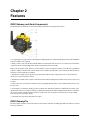
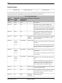
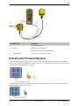
1
SureCross Wireless I/O Products
Manual
132607 Rev. G
Contents
Part I: Introduction.......................................................................................1
Chapter 1: Introducing SureCross........................................................3
The SureCross Wireless Network............................................................................3
SureCross Gateways and Nodes.............................................................................3
GatewayPro and Ethernet Bridge............................................................................3
Host Systems...........................................................................................................3
What is FlexPower?..................................................................................................4
Chapter 2: Features................................................................................5
DX80 Gateway and Node Components...................................................................5
DX80 GatewayPro....................................................................................................5
DX83 Ethernet Bridge..............................................................................................6
DX80 Gateway and Node Wiring Chamber..............................................................7
Pinouts.....................................................................................................................7
DX80 Menu Structure...............................................................................................8
Chapter 3: Dimensions........................................................................13
DX80 Gateway and Node.......................................................................................13
DX80 GatewayPro..................................................................................................13
DX83 Ethernet Bridge............................................................................................14
Part II: Using the SureCross Wireless Network.......................................17
Chapter 4: Setting Up Your Wireless Network....................................19
Applying Power to the Gateway or Node................................................................19
Forming Networks and Assigning Node Addresses Using Extended Address Mode.19
Verify Communications on the Gateway................................................................20
Verify Communications on the Node......................................................................21
Conducting a Site Survey.......................................................................................21
Chapter 5: Installing Your SureCross™ Radios ................................25
Ideal Mounting Conditions......................................................................................25
Watertight Side Holes............................................................................................26
Rotary Switch Access Cover..................................................................................26
Watertight NPT Ports.............................................................................................26
Installation Quick Tips ...........................................................................................27
Basic Remote Antenna Installation........................................................................28
Chapter 6: Advanced Setup.................................................................31
Web-based Configuration.......................................................................................31
What is Extended Address Mode?.........................................................................34
Setting the Maximum System Nodes.....................................................................37
Modbus Communication Parameters.....................................................................37
Default Output Conditions......................................................................................39
Part III: Host Configuration........................................................................43
SureCross DX80 Modbus Register Definitions.............................................................44
Modbus Holding Registers.....................................................................................44
Special Modbus Registers.....................................................................................45
Supported Modbus Function Codes.......................................................................46
Modbus RTU and Modbus/TCP Register Map.......................................................46
Web-based Configuration..............................................................................................48
Banner Engineering Corp.
Minneapolis, MN USA
iii
SureCross Wireless I/O Products Manual
7/2010
Accessing the Web-based Configuration Pages....................................................50
Saving the System Configuration...........................................................................50
Enabling EtherNet/IP Communication Protocol.....................................................51
Message Registers (I/O 7 and 8)..................................................................................55
Error Handling Message Codes.............................................................................55
Informational Message Codes...............................................................................56
Control Registers (I/O 15).............................................................................................56
Control Codes........................................................................................................57
Extended Control Registers (I/O 15 and 16).................................................................59
Extended Control Codes........................................................................................59
Parameter Numbers...............................................................................................60
Host Configuration Examples........................................................................................64
Clearing Error Conditions Using Register Commands...........................................64
Setting the Sample Rate........................................................................................64
Setting the Counter Preset using Register Commands.........................................65
Conducting a Site Survey Using Modbus Commands...........................................65
Part IV: System Layouts.............................................................................67
Stand-Alone Systems....................................................................................................68
Mapped Pairs (DX70).............................................................................................68
Gateway with Multiple Nodes (DX80).....................................................................68
Gateway Configured as a Modbus Master.............................................................69
Modbus RTU.................................................................................................................70
Modbus RTU Host Controlled Operation................................................................70
Modbus RTU with Multiple Slave Devices..............................................................70
Modbus RTU with Multiple Slave Devices - Layout 2.............................................71
Modbus/TCP and EtherNet/IP.......................................................................................72
Host Connected - DX80 GatewayPro.....................................................................72
Data Radios...................................................................................................................73
Data Radios...........................................................................................................73
Data Radios with DX85 Modbus RTU Remote I/O Devices...................................74
Data Radios with a Gateway as the Modbus Master.............................................74
Part V: Sensor Connections......................................................................77
Discrete Inputs..............................................................................................................78
Discrete Inputs, Sinking, Powered using DX80 Terminals......................................78
Discrete Inputs, Sourcing, Powered Externally......................................................78
Discrete Inputs, Sinking, Powered using DX80 Terminals......................................78
Discrete Inputs, Sinking, Powered Externally.........................................................79
Discrete Inputs, MINI-BEAM..................................................................................79
Discrete Outputs............................................................................................................79
Discrete Outputs, Sourcing, Powered using DX80 Terminals................................79
Discrete Outputs, Sourcing, Powered Externally...................................................80
Discrete Outputs, Sinking, Powered using DX80 Terminals...................................80
Discrete Outputs, Sinking, Powered Externally......................................................80
Analog Inputs................................................................................................................81
Analog Inputs, Powered using DX80 Terminals.....................................................81
Analog Inputs, Powered from Switch Power...........................................................81
Analog Inputs, Powered Externally........................................................................82
Analog Inputs, Temperature Sensors.....................................................................82
Analog Inputs, QT50U Long-Range Ultrasonic Sensor.........................................83
Analog Inputs, Proximity Sensors..........................................................................83
Analog Inputs, Pressure Sensors...........................................................................83
Analog Outputs..............................................................................................................84
Analog Outputs, Three-Wire Sensors....................................................................84
Analog Outputs, Drive Motor Controllers...............................................................84
Part VI: Antenna Basics.............................................................................85
What Do Antennas Do?.................................................................................................86
Anatomy of an Antenna..........................................................................................86
Antenna Gain.........................................................................................................87
Line of Sight...........................................................................................................88
Omni-Directional Antennas...........................................................................................89
Directional (Yagi) Antennas...........................................................................................90
Path Loss, or Link Loss, Calculations............................................................................92
iv
Minneapolis, MN USA
Banner Engineering Corp.
7/2010
SureCross Wireless I/O Products Manual
Antenna Installation Warning.........................................................................................94
Weatherproofing Remote Antenna Installations.....................................................94
Mounting an RP-SMA Antenna Directly to the Cabinet..........................................95
Mounting an RP-SMA Antenna Remotely..............................................................96
Mounting N-Type Antennas Remotely....................................................................97
Part VII: SureCross Power Solutions........................................................99
10 to 30V dc Power.....................................................................................................100
What is FlexPower?.....................................................................................................100
Switch Power (with FlexPower)............................................................................101
FlexPower with Integrated Battery........................................................................101
FlexPower Solar Supply.......................................................................................101
Battery Life Calculations..............................................................................................102
Analog Configuration............................................................................................102
Discrete Configuration..........................................................................................103
Temperature and Humidity Sensor.......................................................................104
Calculating Battery Life........................................................................................105
Example Solar Powered Systems...............................................................................106
Parallel Solar Systems.........................................................................................108
Battery Backup Feature.......................................................................................108
Autonomous Process Monitoring with Continuous Sensor Operation..................108
Wireless Network Range Extension.....................................................................109
Part VIII: Maintenance and Troubleshooting..........................................111
Chapter 7: Maintenance.....................................................................113
Replacing the Main Body Gasket.........................................................................113
Replacing the Rotary Switch Access Cover O-Ring............................................113
Battery Replacement...........................................................................................113
Chapter 8: Troubleshooting...............................................................119
Radio Link Time-Out and Recovery (Non-Host Connected Systems).................119
Modbus Error Codes............................................................................................120
LCD Message Codes...........................................................................................121
LED Message Codes...........................................................................................121
Power Problems...................................................................................................123
Site Survey Troubleshooting.................................................................................123
Host Systems.......................................................................................................123
Inputs and Outputs...............................................................................................123
Web Page Configuration......................................................................................124
Restoring Factory Default Settings.......................................................................124
Serial Communication Configuration....................................................................125
Chapter 9: Accessories.....................................................................127
Antennas..............................................................................................................127
DX85 Modbus RTU Remote I/O Devices.............................................................128
FlexPower Supplies and Replacement Batteries.................................................128
FlexPower Sensors..............................................................................................130
Surge Suppressors..............................................................................................131
Cables..................................................................................................................131
Enclosures and Relay Boxes...............................................................................134
Replacement Parts...............................................................................................134
Part IX: Certifications and Additional Information................................137
Chapter 10: Agency Certifications....................................................139
FCC Certification, 900MHz..................................................................................139
FCC Certification, 900 MHz, 1 Watt Radios.........................................................140
FCC Certification, 2.4GHz...................................................................................141
Certified For Use in the Following Countries........................................................142
Exporting SureCross Devices..............................................................................144
Chapter 11: Additional Information..................................................145
Banner Engineering Corp.
Minneapolis, MN USA
v
Units Defined........................................................................................................145
What is Extended Address Mode?.......................................................................148
Setting up the Wireless Network Using the Rotary Dials.....................................149
Host System Software Configuration...................................................................153
Glossary....................................................................................................161
Part 1
Introduction
Topics:
•
•
•
Introducing SureCross
Features
Dimensions
Banner Engineering Corp.
Minneapolis, MN USA
1
7/2010
2
Minneapolis, MN USA
Banner Engineering Corp.
Chapter 1
Introducing SureCross
The SureCross Wireless Network
The SureCross™ DX80 wireless I/O network provides reliable monitoring without the burden of wiring or conduit
installation and can operate independently or in conjunction with a PLC and/or PC software.
The SureCross DX80 network is a deterministic system—the network identifies when the radio signal is lost and drives
relevant outputs to user-defined conditions. Once the radio signal is reacquired, the network returns to normal operation.
Each wireless network system consists of one Gateway and one or more Nodes that ship with factory defined inputs
and outputs. Devices may be all discrete I/O, all analog I/O, mixed discrete and analog I/O, and FlexPower™.
SureCross Gateways and Nodes
A SureCross Gateway device acts as the master device within each radio network, initiates communication and reporting
with the Nodes, and controls the timing for the entire network.
The Gateway also holds the configuration for the network. Every wireless network must have one Gateway that
schedules communication traffic and controls the I/O configuration for the network. A radio network contains only
one Gateway, but can contain many Nodes. Similar to how a gateway device on a wired network acts as a “portal”
between networks, the SureCross Gateway acts as the portal between the wireless network and the central control
process.
Generally, a node is any point within a network. A SureCross Node is a wireless network slave device used to provide
sensing capability in a remote area or factory. The Node collects sensor data from sensors and communicates the data
back to the SureCross Gateway.
SureCross Nodes are available in a wide variety of power or input/output options. Each Node device can be connected
to sensors or output devices and reports I/O status to the Gateway. Devices may be all discrete I/O, mixed discrete and
analog I/O, or FlexPower™.
GatewayPro and Ethernet Bridge
The DX80 GatewayPro combines, in one DX80 unit, the function of a standard Gateway with the ability to interface
to Ethernet using Modbus/TCP or EtherNet/IP™ protocols. The GatewayPro has a serial port as well as an industrial
Ethernet port.
To achieve the same functionality with a standard Gateway, add a DX83 Ethernet Bridge to any standard DX80 Gateway
device. The DX83 Ethernet Bridge adds the Web page configuration ability to your system as well as the ability to
interface to Ethernet using Modbus/TCP or EtherNet/IP protocols. A DX83 Ethernet Bridge connected to a DX80
Gateway functions as a DX80 GatewayPro while allowing the Gateway to have I/O points.
Host Systems
Host-connected systems collect I/O data for logging, controlling other devices, or performing calculations.
Host-connected systems can contain up to 15 Nodes (Rotary Switch addressing) or 56 Nodes (extended addressing
mode) within a single network and may be all discrete, all analog, or a mix of discrete and analog I/O. Inputs from
Nodes within the network are transmitted to the Gateway, which communicates the information to a host device for
processing. While the Gateway is the master device within the radio network, the Gateway may be a slave to the
Modbus network.
Banner Engineering Corp.
Minneapolis, MN USA
3
What is FlexPower?
Banner’s FlexPower technology allows for a true wireless solution by allowing the device to operate using either
10-30V dc, 3.6V lithium D cell batteries, or solar power.
This unique power management system can operate a FlexPower Node and an optimized sensing device for up to five
years on a single lithium D cell.
• The FlexPower Node may be powered from 10 to 30V dc and use an external battery supply module to provide a
battery back-up solution.
• When a FlexPower Node receives 10 to 30V dc, it operates like a standard 10 to 30V dc Node.
• Good applications for FlexPower devices operating from batteries include sensors that require no or very little power,
including dry contacts, RTDs, and thermocouples.
The following FlexPower options are available:
• DX81, a single battery supply module;
• DX81P6, a 6-pack of lithium batteries;
• DX81H, a single battery supply module designed specifically to power the DX99 Intrinsically Safe devices with
polycarbonate housings; and
• BWA-SOLAR-001, a solar power assembly that includes the solar panel, rechargeable batteries, and solar power
controller.
DX81: Single battery supply module DX81P6: Six-pack battery supply
module
DX81H: Single battery supply module
designed specifically to power the
DX99 Intrinsically Safe devices with
polycarbonate housings
BWA-SOLAR-001: Solar supply;
includes solar panel, rechargeable
batteries, and controller.
Chapter 2
Features
DX80 Gateway and Node Components
The DX80 Gateway and Node use the same housing and include the same physical features.
1. Port, NPT gland, or plug. If unused, install the provided plug into the 1/2 NPT threaded port. Refer to the Installation
section if an IP67 seal is required.
2. Rotary switch 1 (left). Sets the Network ID (NID) to a hexidecimal value from 0 to F, for a total of 16 Network IDs.
A Gateway and its corresponding Nodes must be assigned the same Network ID.
Rotary switch 2 (right). On the Gateway, sets the Gateway’s LCD viewing device address. The Gateway is predefined
as Device Address 0. On the Node, sets the Node’s Device Address (hexidecimal 1 to F). Each Node within a network
must have a unique Node Device Address.
3. Push button 1. Single-click to advance across all top-level DX80 menus. Single-click to move down interactive
menus, once a top-level menu is chosen.
4. Push button 2. Double-click to select a menu and to enter manual scrolling mode. Double-click to move up one level
at a time.
5. LED 1 and 2. Provide real-time feedback to the user regarding RF link status, serial communications activity, and
the error state.
6. LCD Display. Six-character display provides run mode user information and shows enabled I/O point status. This
display allows the user to conduct a Site Survey (RSSI) and modify other DX80 configuration parameters without the
use of a PC or other external software interfaces. On the Node, after 15 minutes of inactivity, the LCD goes blank.
Press any button to refresh the display.
7. 5-Pin M12 Euro-style quick-disconnect serial port
DX80 GatewayPro
The GatewayPro has many of the same features as the Gateway and Node, including the LEDs, the buttons, LCD, and
Euro-style connector.
Banner Engineering Corp.
Minneapolis, MN USA
5
Features
7/2010
1. Industrial ethernet port, female.
2. Rotary switch 1 (left). Sets the Network ID (NID) to a hexidecimal value from 0 to F, for a total of 16 Network IDs.
A Gateway and its corresponding Nodes must be assigned the same Network ID.
Rotary switch 2 (right). On the Gateway, sets the Gateway’s LCD viewing device address. The Gateway is predefined
as Device Address 0. On the Node, sets the Node’s Device Address (hexidecimal 1 to F). Each Node within a network
must have a unique Node Device Address.
3. Push button 1. Single-click to advance across all top-level DX80 menus. Single-click to move down interactive
menus, once a top-level menu is chosen.
4. Push button 2. Double-click to select a menu and to enter manual scrolling mode. Double-click to move up one level
at a time.
5. LED 1 and 2. Provide real-time feedback to the user regarding RF link status, serial communications activity, and
the error state.
6. LCD Display. Six-character display provides run mode user information and shows enabled I/O point status. This
display allows the user to conduct a Site Survey (RSSI) and modify other DX80 configuration parameters without the
use of a PC or other external software interfaces. On the Node, after 15 minutes of inactivity, the LCD goes blank.
Press any button to refresh the display.
7. 5-pin M12 Euro-style quick disconnect serial port.
DX83 Ethernet Bridge
The DX83 Ethernet Bridge uses the same housing and same mounting holes as the Gateway and Node.
6
Minneapolis, MN USA
Banner Engineering Corp.
7/2010
Features
1. Industrial ethernet port, female.
2. Housing. The rugged, industrial DX80 housing meets IEC IP67 standards.
3. Mounting hold, #10/M5 clearance. Mounting Holes accept metric M5 or UNC/UNF #10 hardware -- DIN rail mount
adapter bracket available.
4. 5-Pin M12 Euro-style quick-disconnect serial port
DX80 Gateway and Node Wiring Chamber
The DX80 Gateway and Node use the same housing and terminal block for wiring.
1. Housing. The rugged, industrial DX80 housing meets IEC IP67 standards.
2. Mounting hold, #10/M5 clearance. Mounting Holes accept metric M5 or UNC/UNF #10 hardware -- DIN rail mount
adapter bracket available.
3. Wiring terminal strip. The 16 spring-clip type wiring terminals accept wire sizes: AWG 12-28 or 2.5 sq mm.
4. Port, PG-7 gland or blank. The PG-7 threaded ports can accept provided cable glands or blanks.
5. Ribbon connector. Ribbon cable connects wiring base to LCD/radio.
The GatewayPro has no serviceable parts inside the housing and no wiring chamber. During setup or standard operation,
there should not be a need to open the GatewayPro.
Pinouts
5-pin Euro-Style Hookup
Wiring the 5-pin Euro-style connector depends on the model and power requirements of the device.
Wire
No.
Wire
Color
Gateway,
GatewayPro, DX85
FlexPower
Gateway, Data
Radio
10–30V dc Power
1
Brown
10 to 30V dc
10 to 30V dc
10 to 30V dc
2
White
RS485 / D1 / B / +
RS485 / D1 / B / +
Banner Engineering Corp.
Minneapolis, MN USA
Battery Power
7
Features
Wire
No.
7/2010
Wire
Color
Gateway,
GatewayPro, DX85
FlexPower
Gateway, Data
Radio
10–30V dc Power
Battery Power
3
Blue
dc common (GND)
dc common (GND)
dc common (GND)
dc common (GND)
4
Black
RS485 / D0 / A / -
RS485 / D0 / A / -
5
Gray
Comms Gnd
3.6 to 5.5V dc
3.6 to 5.5V dc
Connecting dc power to the communication pins will cause permanent damage. For FlexPower devices, do not apply
more than 5.5V to the gray wire (BAT terminal in models with the mini-board).
DX80...C Hookup
Wiring power to the DX80...C models varies depending the power requirements of the model.
Terminal
Gateway, DX85*
Block Label
V+
10 to 30V dc
Tx
RS485 / D1 / B / +
V-
dc common (GND)
Rx
RS485 / D0 / A / -
10–30V dc Power
Battery Power**
10 to 30V dc
dc common (GND)
dc common (GND)
B+
3.6 to 5.5V dc
* Connecting dc power to the communication pins will cause permanent damage.
** For FlexPower devices, do not apply more than 5.5V to the gray wire.
Industrial Ethernet Hookup
The industrial Ethernet connection is on the DX83 and GatwayPro models and connects the SureCross system to an
Ethernet-based host system.
Wire No.
Wire Color
Description
1
White/Orange
+Tx
2
White/Blue
+Rx
3
Orange
-Tx
4
Blue
-Rx
DX80 Menu Structure
The Gateways, Nodes, and Data Radios each have their own menu structure and options.
DX80 Gateway Set-up Menu
When power is applied, the DX80 begins running. The display screen auto loops through the RUN menu and
communication begins between the Gateway and Node(s). Auto looping through the RUN menu is the normal operating
mode for all devices on the wireless network.
From the RUN Menu (or any menu), single-click button 1 to advance through the top-level menus. The device auto
display loops through the menu options if either of the RUN, DINFO, or FCTRY menus are selected. If the device is
paused on the SITE, DVCFG, or DERR menu options, the display does not auto loop.
8
Minneapolis, MN USA
Banner Engineering Corp.
7/2010
Features
To enter manual scrolling mode, double-click button 2 at the top level menu. Use the instructions shown in the chart
below to navigate the menu system. To return to the top level menus and auto display loop mode, double-click button
2 twice.
The * before the menu name indicates a top-level menu option. The () indicate a submenu items.
The Network ID (NID) can be set at any time using the left rotary switch. Once changed, allow five seconds for the
devices to update to the new Network ID.
DX80 Node Set-up Menu
When power is applied, the DX80 begins running. The display screen auto loops through the RUN menu and
communication begins between the Gateway and Node(s). Auto looping through the RUN menu is the normal operating
mode for all devices on the wireless network.
From the RUN Menu (or any menu), single-click button 1 to advance through the top-level menus. The device auto
display loops through the menu options if either of the RUN, DINFO, or FCTRY menus are selected. If the device is
paused on the DVCFG or DERR menu options, the display does not auto display loop.
To enter manual scrolling mode, double-click button 2 at the top level menu. Use the instructions shown in the chart
below to navigate the menu system. To return to the top level menus and auto display loop mode, double-click button
2 twice.
Node LCD Timeout: After 15 minutes of inactivity, the LCD screen stops displaying information. Press any button to
refresh the display if the Node has entered this energy-saving mode.
The * before the menu name indicates a top-level menu option. The () indicate a submenu items.
The Network ID (NID) and Device ID (NADR) can be set at any time using the rotary switches. The left rotary switch
sets the Network ID and the right rotary switch sets the Node Address. Once changed, allow five seconds for the devices
to update to the new Network ID.
Banner Engineering Corp.
Minneapolis, MN USA
9
Features
7/2010
RUN Menu
The RUN menu displays the network ID, device name, and the I/O values of the device. On a Gateway, the I/O displayed
may be the I/O of the Gateway or of a selected Node, which is determined by the position of the rotary switches.
DINFO (Device Information) Menu
The Device Info menu displays the device-specific information, such as the device name, the network ID, slave ID,
baud rate, and parity. When in extended address mode, the DINFO menu also displays the maximum Node setting and
the extended addressing binding code used to form the network.
FCTRY (Factory) Menu
The FCTRY menu displays the version numbers of various components within the device, including the radio micro
number, the LCD number, the device’s serial number, the device’s model number, and the production date.
SITE (Site Survey) Menu
Access the SITE menu to see the results of a Site Survey conducted with this Gateway. The SITE menu displays the
device number of the Node the Site Survey was conducted with as well as the missed, green, yellow, and red received
10
Minneapolis, MN USA
Banner Engineering Corp.
7/2010
Features
packet count. For more information on determining what these values represent, refer to the Site Survey chapter of
this manual.
The SITE menu is only available on the Gateways.
DVCFG (Device Configuration) Menu
On Gateways, the DVCFG menu allows users to set various device-specific parameters, including the network ID,
slave ID, baud rate, and parity. When in extended address mode, use this menu to set the maximum number of Nodes
within the network and the extended address binding code.
On Nodes, use the DVCFG to set the network ID, Node address (also referred to as a device address), and extended
address binding code.
DERR (Device Error) Menu
On the Gateway
Use the DERR menu to clear, disable, or ignore error messages generated by devices within the network. The Node
number that generated the error and the error code (EC) display onscreen. Single-click button 1 to advance through
the menu of CLEAR (clear this particular instance of the error from the system), DISABL (disable this particular error
from appearing from this specific Node), and IGNORE (ignore this error but do not remove it from the system).
After the error messages for a Node are cleared, disabled, or ignored, errors for any additional Nodes display on the
Gateway’s LCD.
On the Node
Use the DERR menu to view and ignore error messages for that Node.
Banner Engineering Corp.
Minneapolis, MN USA
11
Features
12
7/2010
Minneapolis, MN USA
Banner Engineering Corp.
Chapter 3
Dimensions
DX80 Gateway and Node
The DX80 Gateways and Nodes have the same external and mounting dimensions.
DX80 GatewayPro
The DX80 GatewayPro has the same external and mounting dimensions as the Gateway and Node, but does not have
any side access holes or glands.
Banner Engineering Corp.
Minneapolis, MN USA
13
Dimensions
7/2010
DX83 Ethernet Bridge
Like the GatewayPro, the DX83 Ethernet Bridge has the same external and mounting dimensions, but no side access
holes or glands.
14
Minneapolis, MN USA
Banner Engineering Corp.
7/2010
Banner Engineering Corp.
Dimensions
Minneapolis, MN USA
15
Dimensions
16
7/2010
Minneapolis, MN USA
Banner Engineering Corp.
Part 2
Using the SureCross Wireless Network
Topics:
•
•
•
Setting Up Your Wireless Network
Installing Your SureCross™ Radios
Advanced Setup
Banner Engineering Corp.
Minneapolis, MN USA
17
7/2010
18
Minneapolis, MN USA
Banner Engineering Corp.
Chapter 4
Setting Up Your Wireless Network
Applying Power to the Gateway or Node
Connect power to the Gateway or Node using the wiring table shown.
Wire Color Gateway
Node (10-30V dc)
1
brown
+10 to 30V dc input
10 to 30V dc
2
white
RS485 / D1 / B / +
3
blue
dc common (GND)
4
black
RS485 / D0 / A / -
5
gray
Comms gnd
dc common (GND)
Node (FlexPower)
dc common (GND)
3.6 to 5.5V dc¹
¹ Do not apply more than 5.5V dc to the gray wire.
1. Apply power to the Gateway by connecting the 10 to 30V dc cable as shown in the wiring diagram.
The Gateway begins in *RUN mode, displays the current network ID (NID), then identifies itself as a Gateway.
2. Apply power to the Node by connecting the 10 to 30V dc cable or the DX81 Battery Supply Module as shown.
The Node starts in *RUN mode, displays the current network ID, then identifies itself as a Node and lists the device
ID. Once running, the Node begins displays its I/O points.
Forming Networks and Assigning Node Addresses Using Extended
Address Mode
To select extended address mode, turn the device off. Set DIP switch 1 to the ‘ON’ position, then turn the device on.
Do not set the DIP switch while the power is on to the device.
On the Gateway
To automatically bind the Gateway and its Node(s), follow these steps:
1. Remove the Gateway’s top cover.
2. Move DIP switch 1 to the ON position to activate Extended Addressing Mode.
3. Apply power to the Gateway.
The LCD shows POWER, then *RUN.
4. Triple click button 2 to enter binding mode.
Banner Engineering Corp.
Minneapolis, MN USA
19
Setting Up Your Wireless Network
7/2010
The red LEDs flash alternately when the Gateway is in binding mode. Any Node entering binding mode will bind
to this Gateway. The LCD shows NETWRK BINDNG.
On the Node
1. Remove the Node’s top cover.
2. Mode DIP switch 1 to the ON position to activate Extended Addressing Mode.
3. Apply power to the NODE.
The LCD shows POWER, then *RUN.
4. Use both of the Node’s rotary dials to assign a decimal Node address (device ID) between 01 and 56.
The left rotary dial represents the tens digit (0-5) and the right dial represents the ones digit (0-9) of the Node
address (device ID).
5. Triple click button 2 to enter binding mode.
The Node enters binding mode and locates the Gateway that is also in binding mode. While the Node in binding,
the LCD shows NETWRK BINDNG. When the Node is bound, the LEDs are both solid red for a few seconds.
The Node cycles its power, then entering RUN mode. The LCD shows BOUND, then *RUN.
6. Repeat steps 1 through 5 for each additional Node that needs to communicate to that Gateway.
On the Gateway
1. Single click either button 2 or button 2 on the Gateway.
The Gateway exists binding mode and reboots. The LCD reads POWER, then *RUN.
2. Verify the Gateway and Node are communicating.
IMPORTANT: For special kits, indicated by device model numbers beginning in DX80K, do not change the position
of the right rotary dial. Set the left rotary dial to zero.
Verify Communications on the Gateway
After powering up and binding the Gateway and its Nodes, verify all devices are communicating properly.
Verify LED 1 is on and green.
Status
LED 1
LED 2
Power ON
Green ON
-
System Error
Red flashing
Red flashing
Modbus Communication
Active
-
Yellow flashing
20
Minneapolis, MN USA
Banner Engineering Corp.
7/2010
Setting Up Your Wireless Network
Status
LED 1
Modbus Communication
Error
LED 2
-
Red flashing
For Gateway and Ethernet Bridge systems, active Modbus communication refers to the communication between the
Gateway and the Ethernet Bridge.
For GatewayPro systems, the Modbus communication LEDs refer to the communication internal to the Gateway Pro.
For Gateway only systems, the Modbus communication LEDs refer to the communication between the Gateway and
its host system (if applicable).
Verify Communications on the Node
After powering up and binding the Gateway and its Nodes, verify all devices are communicating properly.
Verify LED 1 is flashing green and LED 2 is off. Until communication is established with the Gateway, the Node’s
LED 2 flashes red. When communication is established, the Node’s LED 1 flashes green.
A Node will not sample its inputs until it is communicating with the Gateway to which it is bound.
Status
LED 1
LED 2
System Error
Red flashing
Red flashing (1 per second)
RF Link Ok
Green flashing (1 per second)
-
RF Link Error
-
Red flashing (1 per 3 seconds)
When testing the Gateway and Node, verify all radios and antennas are at least two meters apart or the communications
may fail.
Conducting a Site Survey
Site Survey (Gateway and Nodes)
Conducting a Site Survey, also known as an RSSI (Radio Signal Strength Indication), analyzes the radio communications
link between the Gateway and any Node within the network by analyzing the radio signal strength of received data
packets and reporting the number of missed packets that required a retry.
Perform a Site Survey before permanently installing the radio network to ensure reliable communication. Activate Site
Survey mode from either the Gateway buttons or the Gateway Modbus holding register 15. Only the Gateway can
initiate a Site Survey, and the Site Survey analyzes the radio communications link with one Node at a time.
Conducting a Site Survey Using the Menu System
A Site Survey can be started from the Menu System.
Banner Engineering Corp.
Minneapolis, MN USA
21
Setting Up Your Wireless Network
7/2010
Follow these steps to initiate a Site Survey using the Gateway’s buttons and menu system.
1. Remove the rotary switch access cover.
2. To check the status of Node 1, change the Gateway’s right rotary switch setting to 1.
The Gateway is now enabled to read the status of Node 1; the display scrolls through the Node’s I/O status.
3. Single-click button 1 to scroll across the menu levels until reaching the Site Survey (*SITE) menu.
4. Single-click button 2 to enter the Site Survey menu.
5. Single-click button 2 to begin conducting a Site Survey with the Node selected in step 2.
The Gateway analyzes the quality of the signal from the selected Node by counting the number of data packets it
receives from the Node.
6. Examine reception readings (M, R, Y, G) of the Gateway at various locations. Note that the numbers displayed are
a percentage. M displays the percent of missed packets while R, Y, and G display the percentage of received packets
at a given signal strength.
M = Percentage of missed packets; R = RED marginal signal; Y = YELLOW good signal; G = GREEN excellent
signal
Record the results if you need troubleshooting assistence from the factory.
7. Change the Gateway's right rotary switch setting to conduct a Site Survey with another Node and repeat steps 2
through 7.
8. To end the Site Survey, double-click button 2.
9. Change the right rotary switch back to 0 (Gateway).
The LCD displays the device readings for the Gateway.
10. Double-click button 2 to move back to the top level menu.
11. Single-click button 1 to return to RUN mode.
12. Install the rotary switch access cover, referring to the Installation section of the manual to create an IP67 seal.
Conducting a Site Survey Using Modbus Commands
A Site Survey can be started using Modbus commands sent from the host system.
All DX80 models reserve the Modbus register I/O 15 (write only) for control messages. The control message code for
the Site Survey command is listed below.
To start a Site Survey using a Modbus write holding register command, send a control code of 32 (0x20) and the Node
number 1–15 (0x01 to 0x0F) to the Gateway Modbus holding register for I/O 15.
Modbus Register
I/O 15
[15:8]
[7:0]
Control Code
Data Field
I/O 15 Control Messages
Control Code Data Field Restrictions
32
Node # 1-15 Gateway only
Description
Enable Site Survey between Gateway and Node defined by the data
field. All error messages from the Gateway are ignored when
running Site Survey.
Only one Node can participate in Site Survey at any given time. To
disable the Site Survey, use control code 0x20 with Node 0. A Node
must be enabled to run the Site Survey, then disabled before
selecting the next Node.
22
Minneapolis, MN USA
Banner Engineering Corp.
7/2010
Setting Up Your Wireless Network
Example Command
Modbus Register
I/O 15
32
02
When Site Survey runs, the accumulated results are stored in the Gateway’s I/O 7 and I/O 8 holding registers. The
LEDs on the both the Gateway and the Node’s front panel display the signal strength for the wireless RF link. The
quality of the communications link is indicated by:
• LED 1 – Green = excellent signal strength
• LED 2 – Yellow = good signal strength
• LED 1 – Red = poor signal strength
The signal strength is the transmitted signal strength relative to the ambient RF signal present in a specific location,
or noise floor.
The Gateway device also displays the Site Survey results on the LCD. For one transmit and receive interval, the Gateway
saves the lowest signal strength. The LCD and Modbus registers contain the results of the last 100 samples. The totals
are a running tally of the last 100 samples and are continuously updated. Four categories are displayed:
•
•
•
•
G = Green – excellent signal strength.
Y = Yellow – good signal strength
R = Red – poor signal strength
M = Missed packet
To disable Site Survey, send a control code of 32 (0x20) and a Node number of 0 (0x0).
Site Survey Data Holding
With Site Survey active, registers I/O 7 and 8 are Site Survey data holding registers that store the accumulated Site
Survey results. Error collections in holding register 8 are saved when Site Survey runs and restored after Site Survey
is disabled.
Register
[15:8]
[7:0]
I/O 7
Missed Total
Red Total
I/O 8
Yellow Total
Green Total
[15:8]
[7:0]
I/O 7
0
10
I/O 8
10
80
Example Results
Note: This is the register arrangement when using Modbus/TCP. When conducting a Site Survey using Modbus RTU
(using the User Configuration Tool), the yellow totals are in bits [0:7] and green totals are in bits [8:15].
Interpreting the Site Survey Results
Site Survey results are listed as a percentage of data packets received and indicate the signal strength of the received
signal.
Banner Engineering Corp.
Minneapolis, MN USA
23
Result
Description
Green
Packets received at a strong signal strength. A strong signal
strength is greater than −90 dBm at the receiver.
Yellow
Packets received at a good signal strength. A good signal is
between −90 and −100 dBm at the receiver.
Red
Packets received at a weak signal strength. A weak signal is
less than −100 dBm at the receiver.
Missed
Packets not received on the first transmission and requiring a
retry.
Judging if the reliability of a network’s signal meets the needs of the application is not simply a matter of green, yellow,
and red packets received. In normal operating mode, when data packets are not received, the transmitter re-sends the
packet until all data is received.
For slow monitoring applications such as a tank farm, where data is required in terms of seconds or minutes, receiving
most of the data in the ‘red’ range, indicating a weak but reliable signal, transmits enough data for accurate monitoring.
Nodes positioned near the outside range of the radio signal may have 90% of the data packets received in the red zone,
again indicating a weak, but reliable signal.
A good rule of thumb is to keep the missed packets average to less than 40%. When the network misses more than
40% of the data packets, the signal is usually too unreliable or obstacles may be interfering with the signal. When Site
Survey reports the missed packets are 40% or higher, improve the radio system performance by:
• Mounting the network’s antennas higher,
• Using higher gain antennas, or
• Adding data radios to the network.
Mounting the devices’ antennas higher allows the radio signal to clear obstacles in the area and improves the line of
sight between SureCross™ devices. Higher gain antennas will focus the energy of the radio signal in a specific direction
and extend the signal’s range. Using data radios is another option to consider when trying to extend the range of a radio
network. For more information on data radios, please refer to Banner’s white paper on range extension.
Site Survey Troubleshooting
Some tips and tricks about improving radio signal reception may improve the site survey results.
Marginal Site Survey (RSSI) Results
If the distance between devices is greater than about 5,000 meters (3 miles) line-of-sight *OR* objects, such as trees
or man-made obstructions, interfere with the path, and the MISSED packet count exceeds 40 per 100 packets, consider
the following steps:
• Raise the DX80 units to a higher elevation, either by physically moving the devices or installing the antenna(s)
remotely at a higher position.
• Use high-gain antenna(s) such as Yagi and/or Omni (see Accessories).
• Decrease the distance between devices.
• Use data radios to extend the position of the Gateway relative to the host system.
Chapter 5
Installing Your SureCross™ Radios
Ideal Mounting Conditions
Ideal mounting conditions include avoiding direct sunlight, mounting so as not to collect rain or snow, reducing chemical
exposure, and minimizing mechanical stress.
Avoid Direct Sunlight
To minimize the damaging effects of ultra-violet radiation, avoid
mounting any SureCross™ device facing intense direct sunlight.
•
•
•
•
Mount within a protective enclosure,
Mount under an overhang or other source of shade,
Install indoors, or
Face the devices north when installing outside.
For harsh outdoor applications, consider installing your SureCross™
radio inside a secondary enclosure. For a list of available enclosures,
refer to the Accessories chapter.
Avoid Collecting Rain
When possible, mount the devices where rain or snow will drain away from the device.
• Mount vertically so that precipitation, dust, and dirt do not accumulate on permeable surfaces.
• Avoid mounting the devices on flat or concave surfaces, especially if the display will be pointing up.
Reduce Chemical Exposure
Before installing any SureCross™ devices in a chemically harsh environment, contact the manufacturer for more
information regarding the life-expectancy. Solvents, oxidizing agents, and other chemicals will damage the devices.
Minimize Mechanical Stress
While these radio devices are very durable, they are sophisticated electronic devices that are sensitive to shock and
excessive loading.
• Avoid mounting the devices to an object that may be shifting or vibrating excessively. High levels of static force or
acceleration may damage the housing or electronic components.
• Do not subject the devices to external loads. Do not step on them or use them as handgrips.
• Do not allow long lengths of cable to hang from the glands on the Gateway or Node. Cabling heavier than 100 grams
should be supported instead of allowed to hang from the housing.
It is the user’s responsibility to install these devices so they will not be subject to overvoltage transients. Always ground
the devices in accordance with local, state, or national regulations.
Banner Engineering Corp.
Minneapolis, MN USA
25
Installing Your Radios
7/2010
Watertight Side Holes
To make the glands watertight, use PTFE tape and follow these steps.
To make the glands watertight:
1. Wrap four to eight passes of polytetrafluoroethylene (PTFE) tape
around the threads as close as possible to the hexagonal body of the
gland.
2. Manually thread the gland into the housing hole. Never apply more
than 5 in-lbf of torque to the gland or its cable clamp nut.*
Seal any unused PG-7 access holes with one of the supplied black plastic plugs. To install a watertight PG-7 plug:
1. Wrap four to eight passes of PTFE tape around the plug’s threads, as close as possible to the flanged surface.
2. Carefully thread the plastic plug into the vacant hole in the housing and tighten using a slotting screwdriver. Never
apply more than 10 in-lbf torque to the plastic plug.
* This is not a lot of torque and is equivalent to the torque generated without using tools. If a wrench is used, apply
only very light pressure. Torquing these fittings excessively damages the device.
Rotary Switch Access Cover
Check the rotary switch access cover o-ring every time the access cover is removed. Replace the o-ring when it is
damaged, discolored, or showing signs of wear.
The o-ring should be:
• Seated firmly against the threads without stretching to fit or without bulging
loosely, and
• Pushed against the flanged cover.
When removing or closing the rotary switch access cover, manually twist the
cover into position. Do not allow cross-threading between the cover and the
devce's face.
Once the cover is in place and manually tightened, use a small screwdriver (no
longer than five inches total length) as a lever to apply enough torque to bring
the rotary switch access cover even with the cover surface.
Watertight NPT Ports
To make the glands and plugs watertight, use PTFE tape and follow these steps.
Watertight 1/2" NPT Glands
To make the glands watertight:
1. Wrap four to eight passes of polytetrafluoroethylene (PTFE) tape around
the threads as close as possible to the hexagonal body of the gland.
2. Manually thread the gland into the housing hole. Never apply more than
5 in-lbf of torque to the gland or its cable clamp nut.*
Watertight 1/2" NPT Plug
Seal the 1/2” NPT port if it is not used. To install a watertight NPT plug:
26
Minneapolis, MN USA
Banner Engineering Corp.
7/2010
Installing Your Radios
1. Wrap 12 to 16 passes of PTFE tape evenly across the length of the threads.
2. Manually thread the plug into the housing port until reaching some resistance.
3. Using a 9/16” crescent wrench, turn the plug until all the plug’s threads are engaged by the housing port or until
the resistance doubles. Do not overtighten as this will damage the SureCross unit. These threads are tapered and
will create a waterproof seal without overtightening.
* This is not a lot of torque and is equivalent to the torque generated without using tools. If a wrench is used, apply
only very light pressure. Torquing these fittings excessively damages the device.
Installation Quick Tips
The following are some quick tips for improving the installation of wireless network components.
Create a Clear Communication Path
Wireless communication is hindered by radio interference and obstructions in the path between the transmitter and
receiver. To achieve the best radio performance, carefully consider the installation locations for the Gateways and
Nodes and select locations without obstructions in the path.
For more information about antennas, please refer to the Antenna Basics reference guide, Banner document p/n 132113.
Increase the Height of the Antennas
Position the external antenna vertically for optimal RF communication. If necessary, consider changing the height of
the SureCross radio, or its antenna, to improve reception. For outdoor applications, mounting the antenna on top of a
building or pole may help achieve a line-of-sight radio link with the other radios in the network.
Avoid Collocating Radios
When the radio network’s master device is located too close to another radio device, communications between all
devices is interrupted. For this reason, do not install a Gateway device within two meters of another Gateway or Node.
Be Aware of Seasonal Changes
When conducting the initial Site Survey, the fewest possible missed packets for a given link is better. However, seasonal
changes may affect the signal strength and the total signal quality. Radios installed outside with 50% missed packets
in the winter months may have 80% or more missed packets in the summer when leaves and trees interfere with radio
reception.
Banner Engineering Corp.
Minneapolis, MN USA
27
Installing Your Radios
7/2010
Basic Remote Antenna Installation
When installing a remote antenna system, always include a lightning arrestor or coaxial surge suppressor in the system.
Remote antenna systems installed without surge protection invalidate the warranty of the radio devices. A remote
antenna system is any antenna system where the antenna is not connected directly to the radio and typically use coaxial
cable to connect the antenna to the radio.
Surge suppressors should be properly grounded and mounted at ground level near where the cabling enters a building.
Install the surge suppressor indoors or inside a weatherproof enclosure to minimize corrosion or component deterioration.
For best results, mount the surge suppressor as close to the ground as possible to minimize the length of the ground
connection and use a single-point ground system to avoid creating ground loops.
For more detailed information about how antennas work and how to install them, refer to the Antenna Basics chapter.
28
Minneapolis, MN USA
Banner Engineering Corp.
7/2010
Installing Your Radios
1. Antenna mounted remotely from the radio device.
2. Coaxial cable
3. Surge suppressor
4. Ground wire to a single-point ground system
I/O Isolation
When connecting analog and discrete I/O to external equipment such as VFDs (Variable Frequency Drives), it may
be appropriate to install interposing relays and/or loop isolation devices to protect the DX80 unit from transients, noise,
and ground plane interference originating from devices or the environment. Contact Banner Engineering Corp. for
more information.
Weatherproofing Remote Antenna Installations
Prevent water damage to the cable and connections by sealing the connections with rubber splicing tape and electrical
tape.
To protect the connections, follow these steps.
Step 1: Verify both connections are clean and dry before connecting the antenna cable to the antenna or other cable
and hand-tightening.
Banner Engineering Corp.
Minneapolis, MN USA
29
Step 2: Tightly wrap the entire connection with rubber splicing tape.
Begin wrapping the rubber splicing tape one inch away from the connection and continue wrapping until you are one
inch past the other end of the connection. Each new round of tape should overlap about half the previous round.
Step 3: Protect the rubber splicing tape from UV damage by tightly wrapping electrical tape on top of the rubber
splicing tape. The electrical tape should completely cover the rubber splicing tape and overlap the rubber tape by one
inch on each side of the connection.
Antenna Installation Warning
Always install and properly ground a qualified surge suppressor when installing a remote antenna system. Remote
antenna configurations installed without surge suppressors invalidate the manufacturer's warranty.
Always keep the ground wire as short as possible and make all ground connections to a single-point ground system to
ensure no ground loops are created. No surge suppressor can absorb all lightning strikes. Do not touch the SureCross™
device or any equipment connected to the SureCross device during a thunderstorm.
Chapter 6
Advanced Setup
Web-based Configuration
The DX80 wireless systems are configured using an Ethernet network connection and a common Web page browser.
An Ethernet connection can be established from a DX80 GatewayPro or from a DX83 Ethernet Bridge serially connected
to the DX80 Gateway.
The Ethernet Bridge and GatewayPro each ship with an Ethernet crossover cable. One end of the cable is a RJ45
connector and the other end is an industrial Ethernet connector. This cable is designed to be connected directly to a
computer. For a list of the accessories, please refer to Accessories on page 127. For more examples of system layouts,
please refer to System Layouts on page 67 .
Example Layout #1
When connecting a DX80 Gateway to a host system, the wireless network must be configured using the User
Configuration Tool (UCT). When you are not using a GatewayPro or Ethernet Bridge, you cannot configure the wireless
network using the Web Configurator.
1. Power connection
2. Splitter cable and Modbus RTU communcation
3. DX80 Gateway
Banner Engineering Corp.
Minneapolis, MN USA
31
Advanced Setup
7/2010
Example Layout #2
This system uses a GatewayPro connected directly to a host system using an Ethernet crossover cable. This system
can be configured using the web pages.
1. Ethernet crossover cable using the Modbus/TCP or EtherNet/IP communication protocol
2. Industrial Ethernet connection
3. DX80 GatewayPro
Example Layout #3
This example system layout may also be configured using the web pages. Instead of using a GatewayPro to connect
to the host system, a Gateway and Ethernet Bridge is used to achieve the same function. In this configuration, the
Gateway is Modbus Slave 1.
1. Ethernet crossover cable using the Modbus/TCP or EtherNet/IP communication protocol
2. Power connection
32
Minneapolis, MN USA
Banner Engineering Corp.
7/2010
Advanced Setup
3. DX83 Ethernet Bridge
4. Splitter cable CSRB-M1250M125.47M125.73 using Modbus RTU
5. DX80 Gateway
Typically, the Modbus RTU connection at a GatewayPro is not used because the GatewayPro contains a master and
slave device. The Modbus RTU factory default settings for a standard Gateway are: 19200 baud; 8 data bits; No stop
bits; 1 parity bit; Modbus Slave ID 1.
Accessing the Web-based Configuration Pages
The configuration Web pages are served from the DX83 Ethernet Bridge or DX80 GatewayPro device and many be
accessed using any Internet browser.
Set up the browser for a direct connection to the Internet. If you are experiencing problems connecting, verify the
browser is not set to use a proxy server (see Appendix A for proxy settings.) Note also that a crossover Ethernet cable
is required when connecting directly from a host computer to the DX83 Ethernet Bridge or DX80 GatewayPro.
The factory default IP address for the DX83 Ethernet Bridge or DX80 GatewayPro devices is: 192.168.0.1
To change the default IP address, set up the host PC with an IP address different from the Ethernet Bridge or Gateway
Pro IP addresses. (Refer to Banner document 133116 for detailed instructions on setting up the host computer’s network
IP address.) For example, change the PC host IP address to: 192.168.0.2
Open a Web browser and log into the Ethernet Bridge or GatewayPro by typing the IP address in the browser location
window: http://192.168.0.1
The Web home page for the Ethernet Bridge or GatewayPro displays. To log in, click on any tab at the top of the page.
Enter the following user name and password:
User name: system
Password: admin
To log out of the configuration system, close the browser.
Changing the IP Address
Use the page tabs at the top of the page to select the hierarchical path: System > Setup > Network. To change the IP
address, type in the new IP address and click the Change IP button. The IP address change activates when the Ethernet
Bridge or GatewayPro reboots (cycles power).
IMPORTANT: Verify the new IP address is correct before cycling power to the device. Once the IP address is changed,
you must enter in the new IP address to access the Web page-based configuration screens. Write down the new IP
address (and any other changed parameters on this screen) or print this page and file for your record.
Banner Engineering Corp.
Minneapolis, MN USA
33
Advanced Setup
7/2010
What is Extended Address Mode?
Extended address mode assigns a unique code, the extended address code, to all devices in a particular network, thereby
controlling which radios can exchange information.
The wireless I/O network is defined by the Network ID (NID) assigned to the Gateway and all its Nodes, ensuring
communication. Each device within this common network also has a unique Device Address assigned.
Extended address mode adds the ability to isolate networks from one another by assigning a unique code, the extended
address code, to all devices in a particular network. Only devices sharing the extended address code can exchange data.
In addition to isolating networks, the extended addressing mode allows up to 56 Nodes to connect to a single Gateway.
Without extended addressing, only 15 Nodes can connect to a single Gateway.
The extended address in the Gateway defaults to a code derived from its serial number although the code can be
customized using the manual binding procedure. Binding DX80 devices locks Nodes to a specific Gateway by teaching
the Nodes the Gateway’s extended address code. After the devices are bound, the Nodes only accept data from the
Gateway to which they are bound.
To select extended address mode, turn the device off. Set DIP switch 1 to the ‘ON’ position, then turn the device on.
Do not set the DIP switch while the device is powered.
Manually Choosing an Extended Address Code
Manually choosing the extended address code is particularly useful when replacing components of an existing wireless
network.
To determine the existing extended address code, access the DINFO (Device Information) menu of either the existing
Gateway or another Node in the network. Follow the submenu structure to the XADR display for that device.
To manually bind a Gateway
1. Remove the Gateway’s top cover.
2. Move DIP switch 1 to the ON position to activate Extended Addressing Mode.
3. Apply power to the Gateway.
The Gateway’s LCD shows POWER, then RUN.
4. On the Gateway, single click button 1 to advance across the menus, stopping at the DVCFG menu.
The Gateway’s LCD shows (DVCFG).
34
Minneapolis, MN USA
Banner Engineering Corp.
7/2010
Advanced Setup
5. Single click button 2 to select DVCFG. Single click button 1 to select from the available menu options, stopping
at XADR.
6. Single click button 2 to enter the XADR menu.
AUTO is automatic binding mode and uses the Gateway’s serial number as the extended address code.
7. Single click button 1 to select manual mode.
8. Single click button 2 to enter manual mode.
MANUAL allows the user to manually enter an extended address code.
9. Single click button 2 to advance to the extended address code entry step.
Once in manual mode, use the right rotary dial to select the digits of the extended address code. The LCD shows
SET XADR 000000.
10. Use the right rotary switch to begin setting the extended address code. Digit selection begins with the left most
digit. After selecting the first digit, single click button 1 to advance right to the next digit. All six digits must be
filled, even if it is with leading zeros. For example, to use 2245 as the code, enter 002245 into the device.
To use the Gateway’s serial number, enter 000000 as the extended addressing code.
11. Continue entering the code using a single click of button 1 to advance from left to right.
Upon reaching the sixth digit, the curser returns to the first digit.
12. Single click button 2 when code entry is complete.
The Gateway LCD displays the entered value for confirmation by showing CONFRM XADR, then repeating back
your value.
13. Single click button 2 to save the code and exit the XADR menu.
When entering the extended address code, the digits auto fill with whatever position the rotary switch is currently in.
For example, after entering the 00 part of the extended address code 002245, the third digit auto fills with a 0 until the
rotary dial is rotated to 2.
After manually changing the extended address code on a Gateway in an existing network, change the extended address
code for all Nodes in that network by either manually setting the code on all Node(s) or by beginning the automatic
binding sequence on the Gateway and auto-binding all the Node(s).
To manually bind a Node
1. Remove the Node’s top cover.
2. Move DIP switch 1 to the ON position to activate extended address mode.
3. Apply power to the Node.*
The LCD displays POWER, then RUN.
4. On the Node, single click button 1 to advance across the menus, stopping at the DVCFG menu.
5. Single click button 2 to select DVCFG. Single click button one to select from the available menu options, stopping
at XADR.
6. Single click button 2 to enter the XADR menu.
AUTO is automatic binding mode and uses the Gateway’s serial number as the extended address code.
7. Single click button 1, stopping at manual mode.
MANUAL allows the user to manually enter an extended address code.
8. Single click button 2 to enter manual mode.
9. Single click button 2 to enter the extended address code entry step.
The LCD shows SET XADR 000000.
10. Use the right rotary switch to begin setting the extended address code. Digit selection begins with the left most
digit. After selecting the first digit, single click button 1 to advance right to the next digit. All six digits must be
filled, even if it is with leading zeros. For example, to use 2245 as the code, enter 002245 into the device.
11. Continue entering the code using a single click of button 1 to advance from left to right.
Upon reaching the sixth digit, the curser returns to the first digit.
12. Single click button 2 when code entry is complete. The Node LCD displays the entered value for confirmation.
The LCD shows CONFRM XADR XXXXXX.
Banner Engineering Corp.
Minneapolis, MN USA
35
Advanced Setup
7/2010
13. If the rotary dial hasn’t been returned to the previous Node address (device address or ID), the LCD displays the
prior setting as a reminder. Return the rotary dial to its previous Node address.
14. The new Node address setting displays (NEW NADR XX).
15. The Node confirms the new Node address by displaying CONFRM NADR XX.
16. Double click button 2 to exit the XADR menu and to return to RUN mode.
When entering the extended address code, the digits auto fill with whatever position the rotary switch is currently in.
For example, after entering the 00 part of the extended address code 002245, the third digit auto fills with a 0 until the
rotary dial is rotated to 2.
* For devices with batteries integrated into the housing, remove the battery for one minute to cycle power to the device.
Setting the Network ID in Extended Addressing Mode
When using extended address mode, use the menu system to set the Network ID.
To set the Network ID, follow these steps on the Gateway:
1. From the top level menus, single click button 1 to advance through the menus, stopping at DVCFG (Device
Configuration).
The Gateway's LCD displays *DVCFG
2. Single click button 2 to enter the DVCFG menu options and stop at (NID).
The Gateway's LCD displays (NID)
3. Single click button 2.
Enters the (NID) menu option.
4. Using both rotary dials on the front of the Gateway, select a Network ID. The left rotary dial acts as the left digit
and the right rotary dial acts as the right digit of the Network ID. In extended addressing mode, the Network ID
can only be set from the rotary dials while in the (NID) menu.
Any Nodes bound to this Gateway ‘follow’ the Gateway to the new Network ID automatically. The current Network
ID and the new Network ID display on the LCD panel.
5. Single click button 2.
Saves the new values.
6. Double click button 2.
Exits this submenu and the LCD displays (NID).
7. Double click button 2.
Exits to the main menu system and returns to RUN mode. The LCD displays *DVCFG.
Automatic Binding Using the Menu Navigation
The easiest way to bind the Gateway to its Nodes is by triple clicking button 2 to enter automatic binding mode. If you
would prefer to begin automatic binding mode using the menu structure instead of the buttons, follow these steps.
1. On the Gateway: remove the top cover.
2. Move DIP switch 1 to the ON position.
Extended Addressing Mode is activated using DIP switch 1.
3. Apply power to the Gateway.
The Gateway's LCD displays POWER, then *RUN.
4. On the Gateway, single click button 1 to advance across the menus, stopping at the DVCFG menu.
The Gateway's LCD displays (DVCFG).
5. Single click button 2 to select DVCFG. Single click button 1 to select from the available menu options, stopping
at XADR.
The Gateway's LCD displays (XADR).
6. Single click button 2 to enter XADR mode. When the display reads (AUTO), single click button 2 again to begin
the automatic binding mode.
36
Minneapolis, MN USA
Banner Engineering Corp.
7/2010
Advanced Setup
The LEDs flash alternately when the Gateway is in binding mode. Any Node entering binding mode will bind to
this Gateway. The Gateway's LCD displays NETWRK BINDNG.
7. On the Node: remove the top cover.
8. Move DIP switch 1 to the ON position.
Extended address mode is activated using DIP switch 1.
9. Apply power to the Node.¹
The Node's LCD displays POWER, then *RUN.
10. On the Node, single click button 1 to advance across the menus, stopping at the DVCFG menu.
The Node's LCD displays (DVCFG).
11. Single click button 2 to enter the DVCFG menu.
12. Single click button 1 to select from the available submenu options, stopping at XADR.
The Node's LCD displays (XADR).
13. Single click button 2 to enter the XADR submenu.
14. When the display reads (AUTO), single click button 2 to begin the automatic binding mode.
The Node enters binding mode. The Node's LCD displays NETWRK BINDNG. When the Node is bound, the
LEDs are both solid red for a few seconds. The Node cycles its power, then enters RUN mode.
15. Use both of the Node’s rotary dials to assign a decimal Device Address between 01 and 56.
The left rotary dial represents the tens digit (0–5) and the right dial represents the ones digit (0–9) of the Device
Address.
16. Repeat steps 7 through 15 for each additional Node that needs to communicate to that Gateway.
17. On the Gateway: single click button 1 or button 2.
When button 1 or 2 is pressed, the Gateway exits binding mode and reboots. The Gateway's LCD displays POWER,
then *RUN.
¹ For devices with batteries integrated into the housing, remove the battery for one minute to cycle power to the device.
After making any changes to DIP switch settings, you must cycle power to the device or the DIP switch changes will
not be recognized.
Setting the Maximum System Nodes
Selecting the maximum number of system Nodes changes the timing for the wireless network.
Use the MAXN submenu, located under the *DVCFG (Device Configuration) menu, to set the maximum number of
Nodes for this system. For example, if you are running four Nodes in your wireless network, set the system's maximum
Node count to 8. This allows up to 8 Nodes in the wireless network and offers the highest throughput, 62.5 milliseconds,
for each Node. The choices are 8, 16, 32, and 56 Nodes.
Modbus Communication Parameters
To access the Modbus device, you may first need to configure system-level communication parameters on the DX80
Gateway, in addition to the serial hookups shown below. The following procedure is necessary to change the Gateway
Slave ID, Baud Rate, and Parity.
Setting up the Network and Device IDs, powering up the devices, and conducting the Site Survey for a host-connected
network is the same as for the non-host DX80 wireless system. All device I/O for the network is accessed using the
host/master device.
Parameter
Default Value
Description
Slave ID
1
Defines the slave number (01-99) for the serial Modbus RTU protocol. When
operating more than one network with a Modbus Master device, change the Slave
IDs.
Baud Rate
19200
Defines communication data rate (19.2, 38.4 or 9.6 kbps) between the Gateway
and the Host through the serial interface.
Parity
None
Defines serial parity (none, even, or odd) between Gateway and Host.
Banner Engineering Corp.
Minneapolis, MN USA
37
Advanced Setup
7/2010
Setting the Slave ID on a DX80 Gateway
By default, all Gateways are set to Modbus Slave ID 1.
To change the Slave ID on the Gateway, follow these steps.
1. Single click button 1 to advance between menus. Stop when you reach the DVCFG menu.
2. Press button 2 once at the *DVCFG menu to enter the Device Configuration menu.
3. Press button 1 to advance through the items in the *DVCFG menu. Stop advancing when you've reached the setting
for the slave ID (SLID).
The screen is displaying (SLID).
4. Press button 2 once to enter the slave ID (SLID) submenu.
The screen displays the current slave ID number.
5. Press button 1 to advance across the three digit slave ID while using the right rotary dial to select the number. To
make a change, rotate the right rotary dial to zero, then to the desired number.
As you press button 1 to select the digit, the digit changes to reflect the position of the right rotary dial. To set the
slave ID to 3, the display should read 003.
6. Press button 2 once to save your current setting.
The display reads SAVED.
7. Double click button 2 to exit the *DVCFG menu.
8. If using a Network ID (NID), adjust both rotary switches back to the NID value.
To avoid losing the network connection between the Gateway and Nodes, reset the rotary switches back to their
appropriate values before leaving the *DVCFG sub-menus. If the Gateway and Nodes lose their connection, the
network may take up to 20 seconds to re-synchronize.
9. Double-click Gateway push button 2 to return to the Device Configuration (*DVCFG) menu.
10. Click Gateway push button 1 until reaching the *RUN menu option.
Setting the Baud Rate
Setting the baud rate establishes the communication rate between the Gateway and the host system to which it is wired.
Continuing from the previous menu position, follow these steps to set the baud rate.
1. Single-click Gateway push button 1 to move to the next menu option, the BAUD rate.
2. Single-click Gateway push button 2 to display the current setting. Single-click Gateway push button 1 to cycle
through the available options. Stop on the desired setting.
The options are 9600, 19200, 38400. The factory default is 19200.
3. Single-click Gateway push button 2 to save the new setting.
4. If using a network ID (NID), adjust both rotary switches back to the NID value.
To avoid losing the network connection between the Gateway and Nodes, reset the rotary switches back to their
appropriate values before leaving the *DVCFG sub-menus. If the Gateway and Nodes lose their connection, the
network may take up to 20 seconds to re-synchronize.
5. Double-click Gateway push button 2 to return to the Device Configuration (*DVCFG) menu.
6. Click Gateway push button 1 until reaching the *RUN menu option.
Setting Parity
Continuing from the previous menu position, follow these steps to set the parity.
1. Single-click Gateway push button 1 to move to the next field, the PARITY field.
2. Single-click Gateway push button 2 to display the current setting. Single-click Gateway push button 1 to cycle
through the available options. Stop on the desired setting.
The options are NONE, EVEN, ODD. The factory default is NONE.
3. Single-click Gateway push button 2 to save the new setting.
38
Minneapolis, MN USA
Banner Engineering Corp.
7/2010
Advanced Setup
4. If using a network ID (NID), adjust both rotary switches back to the NID value.
To avoid losing the network connection between the Gateway and Nodes, reset the rotary switches back to their
appropriate values before leaving the *DVCFG sub-menus. If the Gateway and Nodes lose their connection, the
network may take up to 20 seconds to re-synchronize.
5. Double-click Gateway push button 2 to return to the Device Configuration (*DVCFG) menu.
6. Click Gateway push button 1 until reaching the *RUN menu option.
Default Output Conditions
Default Output Conditions
The timeout structure of the DX80 system sets relevant outputs to user-defined conditions when radio or host
communications fail.
If the timeout features are enabled, the outputs are set to default states or the last known state before the error. The
timeout error conditions are cleared by either a reset command sent from the host, by using the front panel display, or
by using the auto-recover feature on the DX80. Communications timeouts occur in three areas within the DX80 system:
• Host Link Failure to the DX80 Gateway device (Modbus Timeout)
• Gateway Link Failure with any Node device
• Node Link Failure with the Gateway
Host Link Failure
A host link failure is detected when the defined timeout period has elapsed with no communications between the host
system (or Modbus master device) and the DX80 Gateway, typically set to four seconds.
The Gateway places an error code in the Gateway I/O 8 register and sends a message to all relevant Nodes within the
system to set outputs to the user-defined default states. Each Node has an enable flag for a host link failure condition.
If the Node’s ‘host link failure’ flag is not set, the outputs on this Node are not affected.
In the example shown, a host link failure between the host system and the Gateway would result in the outputs of Node
1 and Node 2 sent to the defined conditions if both Nodes have the host link failure checkbox selected.
Banner Engineering Corp.
Minneapolis, MN USA
39
Advanced Setup
7/2010
Gateway Link Failure
Gateway link failure and Node link failure conditions are determined by three global parameters, ‘Polling Interval’,
‘Maximum Missed Message Count’ and ‘Re-link Count.’
The Polling Interval defines how often the Gateway communicates with each Node to verify the RF link is operating.
The Gateway increments a Node’s missed message count if a Node does not immediately report back from a polling
request. If a Node’s missed message count exceeds the ‘Maximum Missed Message Count,’ the Gateway generates a
timeout error in the Modbus I/O 8 register of the appropriate Node.
The auto-recover feature uses the ‘Re-link Count’ parameter. If enabled, the error condition heals itself if the Gateway
to Node communications have successfully exchanged N-number of good polling messages. The N-number is the
‘Re-link Count,’ or the number of messages required to re-establish a RF link.
When the Node’s ‘Gateway Link Failure’ flag is set and the Gateway determines a timeout condition exists for a Node,
any outputs linked from the failing Node are set to the user-defined default state. Each Node has a ‘Gateway Link
Failure’ flag that can be set or cleared depending on the particular application.
In the sample system shown, the communication link between the Gateway and Node 1 has failed. Node 2 must have
its ‘Gateway Link Failure’ flag set to allow its outputs that are linked to Node 1 are set to the defined default state
when the communication link between Node 1 and the Gateway fails.
Node Link Failure
A Node Link Failure may be determined by the polling interval or the out-of-sync timing.
When a Node detects a communications failure with the Gateway and the ‘Node Link Failure’ flag is set, the output
points are set to the user-defined states and the inputs are frozen. When output points are set to their default states
because of an error condition, only the Gateway can clear the error condition and resume normal operation. The front
panel buttons or the Gateway’s register I/O 15 clear error conditions.
Clearing a lost RF link error does not restore communications. Banner recommends determining and resolving the
cause of the RF link error, then allowing the system to auto-recover the lost communications.
40
Minneapolis, MN USA
Banner Engineering Corp.
7/2010
Advanced Setup
In the sample system shown, the communication link between the Gateway and Node 1 has failed. Node 1 must have
its ‘Node Link Failure’ flag set to allow its outputs to be set to the defined default state when it cannot communicate
with the Gateway.
Polling Interval. The global ‘polling interval’ defines the time interval during which the Node should expect a polling
request from the Gateway.
Out of Sync. An ‘out of sync’ condition is met when a Node fails to receive the Gateway’s beacon within a factory-set
time period, about 10 seconds. Both the ‘out of sync’ and ‘polling interval’ conditions are used to detect a failure
because the Node can remain in sync with the Gateway but be unable to transmit data. If the Gateway drops out of the
network, the Nodes will detect the ‘out of sync’ condition long before the polling interval expires.
Banner Engineering Corp.
Minneapolis, MN USA
41
Advanced Setup
42
7/2010
Minneapolis, MN USA
Banner Engineering Corp.
Part 3
Host Configuration
The SureCross™ DX80 Gateway uses Modbus RTU, Modbus/TCP, or EtherNet/IP™ protocols to communicate with
host systems or external devices.
• The Modbus Serial Line RTU protocol is a master-slave protocol typically used for industrial applications. Only
one master at any given time is connected to the bus while up to 247 slaves nodes can be connected to the serial bus.
• The Modbus TCP/IP protocol is an open standard implementation of Modbus on Internet protocols. Modbus TCP/IP
is similar to Modbus RTU but transmits information within TCP/IP data packets.
• EtherNet/IP is also an application layer protocol for industrial automation. EtherNet/IP is built on the TCP/IP
protocols and uses standard Ethernet hardware.
Modbus is the native protocol for the DX80 wireless system. All wireless devices are organized with a two-byte register
for each I/O point. Sixteen registers are allocated for each device, typically eight registers for inputs and eight registers
for outputs. In the world of Modbus, these registers are addressed consecutively beginning with the Gateway, then
Node 1 through Node N.
EtherNet/IP separates the input registers and output registers into blocks. The two blocks of registers, or instances, are
consecutively ordered from the Gateway, then Node 1 through Node 15. The EtherNet/IP interface implementation
also allows for 100 extra input and output registers that can be customized for specific applications.
This configuration guide outlines the procedures involved in configuring I/O parameters by writing to registers.
Parameter configuration using registers can be done with a host system connected to a Gateway, GatewayPro, or
Gateway and Ethernet Bridge combination and any supported protocol.
For more information on Modbus, including basic reference guides, please refer to www.modbus.org. For more
information on specific SureCross components, refer to the data sheets for the SureCross devices.
EtherNet/IP™ is a trademark of ControlNet International, Ltd and Open DeviceNet Vendor Association, Inc.
Topics:
•
•
•
•
•
•
SureCross DX80 Modbus Register Definitions
Web-based Configuration
Message Registers (I/O 7 and 8)
Control Registers (I/O 15)
Extended Control Registers (I/O 15 and 16)
Host Configuration Examples
Banner Engineering Corp.
Minneapolis, MN USA
43
7/2010
SureCross DX80 Modbus Register Definitions
Modbus distinguishes between inputs and outputs and between bit-addressable and word addressable data items.
For more information, please refer to www.modbus.org. A less documented but commonly used method to separate
the data types is using a mapped address structure.
Reference
Description
0xxxx
Read/Write Discrete Output. Drives output data to a discrete output point.
1xxxx
Read Discrete Inputs. Controlled by the corresponding discrete input point.
3xxxx
Read Input Registers. Contains a 16-bit number received from an external source, like an
analog signal.
4xxxx
Read/Write Output or Holding Registers. Stores 16-bits of numerical data (binary or
decimal), or sends the data to an output point.
The xxxx shown in the preceding table represents the four-digit address location in user data memory. Because function
codes generally denote the leading character, the leading character is omitted from the address specifier for a given
function. The leading character also identifies the I/O data type. The SureCross™ DX80 Modbus registers are all
holding registers 4xxxx using the mapped address structure.
Modbus Holding Registers
There are sixteen Modbus holding registers for each SureCross™ device. Calculate the holding register number for
each device using the equation: Register number = I/O# + (Node# × 16).
Since the Gateway is always first, at Node 0, the Gateway’s holding registers are registers 1 through 16. Registers for
Node 1 are 17 through 32, as shown in the Modbus Holding Register table below. Though only ten Nodes are shown,
the table can continue for as many Nodes as are used in a given network.
Using the equation or the Modbus Holding Registers table, the register number for I/O point 15 for Node 7 is 127.
Modbus Holding Registers
I/O Pt.
44
Gateway Node 1
Node 2
Node 3
Node 4
Node 5
Node 6
Node 7
Node 8
1
1
17
33
49
65
81
97
113
129
2
2
18
34
50
66
82
98
114
130
3
3
19
35
51
67
83
99
115
131
4
4
20
36
52
68
84
100
116
132
5
5
21
37
53
69
85
101
117
133
6
6
22
38
54
70
86
102
118
134
7
7
23
39
55
71
87
103
119
135
8
8
24
40
56
72
88
104
120
136
9
9
25
41
57
73
89
105
121
137
10
10
26
42
58
74
90
106
122
138
11
11
27
43
59
75
91
107
123
139
12
12
28
44
60
76
92
108
124
140
13
13
29
45
61
77
93
109
125
141
14
14
30
46
62
78
94
110
126
142
Minneapolis, MN USA
Banner Engineering Corp.
7/2010
Modbus Holding Registers
I/O Pt.
Gateway Node 1
Node 2
Node 3
Node 4
Node 5
Node 6
Node 7
Node 8
15
15
31
47
63
79
95
111
127
143
16
16
32
48
64
80
96
112
128
144
Special Modbus Registers
Special Modbus registers include the device status registers and the system discrete registers.
Device Status Registers 0xC00–0xC003 (49152–49156)*
The Device Status registers contain a bit-packed representation defining the devices that are operational in the wireless
system. A Modbus holding register Read (function 0x03) of the four holding registers returns eight bytes of data, one
bit representing each possible device in the system. If a bit contains a ‘1’ value, the device is operating in the system
(I/O 8 register equals 128), otherwise the bit is a ‘0’ value. Bit 0 of the 64-bit word represents the Gateway device, bit
1 represents Node 1, bit 2 is Node 2, etc.
Modbus Read Holding Registers Function Code
Request
Function code
Byte 1
0x03
Starting address
Bytes 2, 3
0xC0 00
Quantity of registers
Bytes 4, 5
0x00 04
Function code
Byte 1
0x03
Byte count
Byte 2
0x08
Register 0xC000 (49152) – Devices
15:0
Bytes 3, 4
Bit pack for devices 15:1, Gateway
Register 0xC001 (49153) – Devices
31:16
Bytes 5, 6
Bit pack for devices 31:16
Register 0xC002 (49154) – Devices
47:32
Bytes 7, 8
Bit pack for devices 47:32
Register 0xC003 (49156) – Devices
63:48
Bytes 9, 10
Bit pack for devices 63:48
Response
* Decimal values are in ( )
System Discrete Registers 0xCn00–0xCn03 (49408–51203)
The System Discrete Modbus registers show the discrete value for single I/O point for every device in the system. The
returned eight bytes of data include 1 bit for every device in the system. The input point selected is based on the Modbus
register address range.
Modbus Holding Register
Address (Hex)
Modbus Holding Register
Address (Decimal)
System Wide Input Bit Pack
0xC100-0xC103
49408-49411
Input point #1
Banner Engineering Corp.
Minneapolis, MN USA
45
7/2010
Modbus Holding Register
Address (Hex)
Modbus Holding Register
Address (Decimal)
System Wide Input Bit Pack
0xC200-0xC203
49664-49667
Input point #2
0xC300-0xC303
49920-49667
Input point #3
0xC400-0xC403
50176-50179
Input point #4
0xC500-0xC503
50432-50435
Input point #5
0xC600-0xC603
50688-50691
Input point #6
0xC700-0xC703
50944-50947
Input point #7
0xC800-0xC803
51200-51203
Input point #8
Supported Modbus Function Codes
The supported Modbus function codes are 0x03 (read), 0x06 (write single), and 0x10 (write multiple).
All DX80 Modbus registers are defined as ‘holding registers’ in the 4xxxx address space. The first 16 registers are
allocated to the Gateway (1 through 16), the following 16 registers are allocated to Node #1 (17 through 32), the next
16 registers to Node #2 (33 through 48) and so on. The supported Modbus function codes are defined below.
Function
Code
Description
3
0x03
Read Holding Registers, 1 – 125, contiguous block of holding regs.
6
0x06
Write Single Register
16
0x10
Write Multiple Registers, 1 – 0x78, contiguous block of registers
03 (0x03) Read Holding Registers
This function code reads the contents of a contiguous block of holding registers in a remote device. The request specifies
the starting register address and the number of registers.
06 (0x06) Write Single Holding Register
This function code writes a single holding register in a remote device. The request specifies the address of the register
to be written and the single register of data.
16 (0x10) Write Multiple Holding registers
This function code writes a block of contiguous registers (1 to about 120 registers) in a remote device. The requested
written values are specified in the request data field.
For more information about Modbus, see www.modbus.org.
Modbus RTU and Modbus/TCP Register Map
Modbus/TCP and Modbus RTU provide device control and monitoring using holding registers in the 40000 register
block.
Each wireless device in the system is allocated 16 holding registers. The Gateway uses the first 16 registers followed
by each Node in the network, based on the Node address. For Node 5, the starting Modbus registers are 1 + (Node# ×
16) = 1 + (5 × 16) = 81, the ending register is 97.
46
I/O Point
Gateway Modbus Holding
Register
Node Modbus Register
1
1
1 + (Node# × 16)
2
2
2 + (Node# × 16)
3
3
3 + (Node# × 16)
Minneapolis, MN USA
Banner Engineering Corp.
7/2010
I/O Point
Gateway Modbus Holding
Register
Node Modbus Register
4
4
4 + (Node# × 16)
5
5
5 + (Node# × 16)
6
6
6 + (Node# × 16)
7
7
7 + (Node# × 16)
8
8
8 + (Node# × 16)
9
9
9 + (Node# × 16)
10
10
10 + (Node# × 16)
11
11
11 + (Node# × 16)
12
12
12 + (Node# × 16)
13
13
13 + (Node# × 16)
14
14
14 + (Node# × 16)
15
15
15 + (Node# × 16)
16
16
16 + (Node# × 16)
For example:
Registers Device and Input
Connections
Register
Device and Input
Connections
Register
Device and Input
Connections
1
Gateway I/O 1
17
Node #1 I/O 1
33
Node #2 I/O 1
2
Gateway I/O 2
18
Node #1 I/O 2
34
Node #2 I/O 2
3
Gateway I/O 3
19
Node #1 I/O 3
35
Node #2 I/O 3
4
Gateway I/O 4
20
Node #1 I/O 4
...
...
5
Gateway I/O 5
21
Node #1 I/O 5
...
...
6
Gateway I/O 6
22
Node #1 I/O 6
...
...
7
Gateway I/O 7
23
Node #1 I/O 7
...
...
8
Gateway I/O 8
24
Node #1 I/O 8
...
...
9
Gateway I/O 9
25
Node #1 I/O 9
905
Node #56 I/O 9
10
Gateway I/O 10
26
Node #1 I/O 10
906
Node #56 I/O 10
11
Gateway I/O 11
27
Node #1 I/O 11
907
Node #56 I/O 11
12
Gateway I/O 12
28
Node #1 I/O 12
908
Node #56 I/O 12
13
Gateway I/O 13
29
Node #1 I/O 13
909
Node #56 I/O 13
14
Gateway I/O 14
30
Node #1 I/O 14
910
Node #56 I/O 14
15
Gateway I/O 15
31
Node #1 I/O 15
911
Node #56 I/O 15
16
Gateway I/O 16
32
Node #1 I/O 16
912
Node #56 I/O 16
Banner Engineering Corp.
Minneapolis, MN USA
47
7/2010
Web-based Configuration
The DX80 wireless systems are configured using an Ethernet network connection and a common Web page browser.
An Ethernet connection can be established from a DX80 GatewayPro or from a DX83 Ethernet Bridge serially connected
to the DX80 Gateway.
The Ethernet Bridge and GatewayPro each ship with an Ethernet crossover cable. One end of the cable is a RJ45
connector and the other end is an industrial Ethernet connector. This cable is designed to be connected directly to a
computer. For a list of the accessories, please refer to Accessories on page 127. For more examples of system layouts,
please refer to System Layouts on page 67 .
Example Layout #1
When connecting a DX80 Gateway to a host system, the wireless network must be configured using the User
Configuration Tool (UCT). When you are not using a GatewayPro or Ethernet Bridge, you cannot configure the wireless
network using the Web Configurator.
1. Power connection
2. Splitter cable and Modbus RTU communcation
3. DX80 Gateway
Example Layout #2
This system uses a GatewayPro connected directly to a host system using an Ethernet crossover cable. This system
can be configured using the web pages.
48
Minneapolis, MN USA
Banner Engineering Corp.
7/2010
1. Ethernet crossover cable using the Modbus/TCP or EtherNet/IP communication protocol
2. Industrial Ethernet connection
3. DX80 GatewayPro
Example Layout #3
This example system layout may also be configured using the web pages. Instead of using a GatewayPro to connect
to the host system, a Gateway and Ethernet Bridge is used to achieve the same function. In this configuration, the
Gateway is Modbus Slave 1.
1. Ethernet crossover cable using the Modbus/TCP or EtherNet/IP communication protocol
2. Power connection
3. DX83 Ethernet Bridge
4. Splitter cable CSRB-M1250M125.47M125.73 using Modbus RTU
5. DX80 Gateway
Banner Engineering Corp.
Minneapolis, MN USA
49
7/2010
Typically, the Modbus RTU connection at a GatewayPro is not used because the GatewayPro contains a master and
slave device. The Modbus RTU factory default settings for a standard Gateway are: 19200 baud; 8 data bits; No stop
bits; 1 parity bit; Modbus Slave ID 1.
Accessing the Web-based Configuration Pages
The configuration Web pages are served from the DX83 Ethernet Bridge or DX80 GatewayPro device and many be
accessed using any Internet browser.
Set up the browser for a direct connection to the Internet. If you are experiencing problems connecting, verify the
browser is not set to use a proxy server (see Appendix A for proxy settings.) Note also that a crossover Ethernet cable
is required when connecting directly from a host computer to the DX83 Ethernet Bridge or DX80 GatewayPro.
The factory default IP address for the DX83 Ethernet Bridge or DX80 GatewayPro devices is: 192.168.0.1
To change the default IP address, set up the host PC with an IP address different from the Ethernet Bridge or Gateway
Pro IP addresses. (Refer to Banner document 133116 for detailed instructions on setting up the host computer’s network
IP address.) For example, change the PC host IP address to: 192.168.0.2
Open a Web browser and log into the Ethernet Bridge or GatewayPro by typing the IP address in the browser location
window: http://192.168.0.1
The Web home page for the Ethernet Bridge or GatewayPro displays. To log in, click on any tab at the top of the page.
Enter the following user name and password:
User name: system
Password: admin
To log out of the configuration system, close the browser.
Saving the System Configuration
Save the system configuration by going to the System > Setup > Config File page.
• To write the changes to the factory default XML file (BootConfig.xml), click the Save button.
• To save the configuration changes under a different file name, enter the new XML file name, including the .XML
extension, in the New File Name box and click the Save As button.
To define which XML configuration file loads when the device cycles power or restarts, enter the file name in the
Startup Configuration box.
Cycle power to the Ethernet Bridge or GatewayPro to complete this update. After the device powers up, the changes
should be registered.
50
Minneapolis, MN USA
Banner Engineering Corp.
7/2010
Enabling EtherNet/IP Communication Protocol
By default the Ethernet Bridge and GatewayPro systems communicate using Modbus/TCP, but the system can also
use EtherNet/IP™.
To change the system to EtherNet/IP, log in using the following user name and password.
User name: root
Password: sxi
At the bottom of the System > Setup > Network page is a checkbox to enable EtherNet/IP. Only select this box if the
GatewayPro system is running on an EtherNet/IP network. This change cannot be enabled from a login other than the
“root” login.
After selecting the EtherNet/IP Enabled checkbox, click the Set Ports button to save any changes made to the HTTP
Port, Modbus Server Port, Telnet Port, and EtherNet/IP Enabled box. Cycle power to the Ethernet Bridge or GatewayPro
to complete this update. After the device powers up, the changes should be registered.
For some SureCross devices, the Ethernet/IP checkbox may be enabled as the factory default.
To use EtherNet/IP, the GatewayPro or DX83 Ethernet Bridge interface requires the user to enable the EtherNet/IP
interface, define the EtherNet/IP registers, and save the system configuration using the System > Setup > Config File
page.
Banner Engineering Corp.
Minneapolis, MN USA
51
7/2010
Defining EtherNet/IP Registers to Send to the Buffer
Define the registers sent to the EtherNet/IP interface buffers.
On the System > Data > Local Registers tabs, select the EtherNet/IP checkbox for every register to be visible by
Ethernet/IP. After selecting the registers, click the Update button to save the changes on this configuration page.
For some SureCross devices, the EtherNet/IP checkbox may be enabled at the factory.
In the example screen shown, Node #1 Tank Alarm is mapped to EtherNet/IP buffer input 1, Node #1 Tank Level is
mapped to buffer input 2, and Node #1 Status is mapped to buffer input 3. Only local registers defined by the EIP
checkbox will be mapped to the EtherNet/IP buffer inputs.
After all selected inputs for device 1 are mapped to the EtherNet/IP buffer inputs, EIP selected inputs for the remaining
devices are mapped in the order of the device (e.g. device 1, device 2, device 3).
The following tables show how the selecting inputs and outputs using the EIP checkbox maps device registers to the
EIP buffer inputs and outputs.
52
Minneapolis, MN USA
Banner Engineering Corp.
7/2010
EtherNet/IP Registers
EtherNet/IP on ControlLogix PLC Register Map
The DX80 wireless system is controlled by a ControlLogix PLC using EtherNet/IP through assembly objects and the
Common Industrial Protocol (CIP). Add the SureCross Gateway to the ControlLogix PLC as a “Generic Ethernet
Module.”
There is one input assembly object for all DX80 input points and one output assembly object for all DX80 output
points. Each object is 228 elements long, with each element a 16-bit integer.
Input Assembly Object, DX80 Input, Instance 100 (0x64)
Words are not allocated for any specific unit but are used, in device order, for each of the device input registers selected
using the EIP checkbox.
Output Assembly Object, DX80 Outputs, Instance 112 (0x70)
Words are not allocated for any specific unit but are used, in device order, for each of the device output registers
selected using the EIP checkbox.
For proper EtherNet/IP communication, the minimum requested packet interval should be 50 milliseconds or higher.
Banner Engineering Corp.
Minneapolis, MN USA
53
7/2010
Instance 100
Instance 112
Word #
Inputs
Word #
Outputs
0
Input 1
0
Output 1
1
Input 2
1
Output 2
2
Input 3
2
Output 3
3
Input 4
3
Output 4
4
Input 5
4
Output 5
5
Input 6
5
Output 6
6
Input 7
6
Output 7
7
Input 8
7
Output 8
8
Input 9
8
Output 9
9
Input 10
9
Output 10
10
Input 11
10
Output 11
11
Input 12
11
Output 12
12
Input 13
12
Output 13
13
Input 14
13
Output 14
14
Input 15
14
Output 15
15
Input 16
15
Output 16
…
…
…
…
…
…
…
…
…
…
…
…
225
Input 226
225
Output 226
226
Input 227
226
Output 227
227
Input 228
227
Output 228
EtherNet/IP to PLC5 and SLC5 Register Map
Allen-Bradley’s PLC5 and SLC5 family of devices use PCCC communications over EtherNet/IP. The DX80 wireless
system supports these PLCs using input and output register arrays.
There is one input assembly object for all DX80 input points and one output assembly object for all DX80 output
points. Each object is 228 elements long, with each element a 16-bit integer. The DX80 wireless data table addresses
are N7 for read and N14 for write. The MSG instruction only handles up to 103 words; use multiple MSG instructions
if all data is required.
N7 - Read Registers
54
N14 - Write Registers
0
Input 1
0
Output 1
1
Input 2
1
Output 2
2
Input 3
2
Output 3
3
Input 4
3
Output 4
4
Input 5
4
Output 5
5
Input 6
5
Output 6
Minneapolis, MN USA
Banner Engineering Corp.
7/2010
N7 - Read Registers
N14 - Write Registers
6
Input 7
6
Output 7
7
Input 8
7
Output 8
8
Input 9
8
Output 9
9
Input 10
9
Output 10
10
Input 11
10
Output 11
11
Input 12
11
Output 12
12
Input 13
12
Output 13
13
Input 14
13
Output 14
14
Input 15
14
Output 15
15
Input 16
15
Output 16
…
…
…
…
…
…
…
…
…
…
…
…
225
Input 226
225
Output 226
226
Input 227
226
Output 227
227
Input 228
227
Output 228
Message Registers (I/O 7 and 8)
Informational messages are warning or error conditions that include a message code and data field.
The type of warning or error condition is encoded in the message code while the data field contains additional information
for some message codes.
Each DX80 model reserves four registers (defined I/O points) to provide information or control an operation. The
reserved registers (I/O points) are 7, 8, 15, and 16. Informational messages are transmitted using Modbus I/O 8 register;
control messages are transmitted using register I/O 15. Registers 7 and 16 have special functions depending on the
action requested.
Error Handling Message Codes
All device errors are captured and sent to the Gateway for storage in the devices’ register for I/O point 8.
All messages are sent to the Gateway regardless of the priority, and redundant messages are not sent more than once.
For example, if a communications timeout is detected 10 times in a row, the device sends the timeout message only
once.
The Gateway stores only the highest priority message in the register. A 0x00 message will not be saved unless there
is a 0x0 in the I/O point register. All non-zero messages must be cleared by the user. A value of 254 in the register for
I/O point 8 disables all error reporting.
To clear any I/O point 8 device message, use the Gateway’s front panel menu system. A host connection can also
choose to clear or disable Modbus I/O 8 registers. A Node device ignores error messages; errors must be cleared from
either the Gateway or the host. The auto-recover feature allows for automatic erasing of errors for a Node if the error
condition ‘heals’ itself. For example, an RF communications link disrupted by a temporary obstacle ‘heals’ itself when
the obstruction is removed. Auto recovery is enabled by factory default and is the recommended setting.
Any new error/warning messages interrupt the active front panel. Once the user has confirmed receipt of the message,
the user can clear, disable, or ignore the error/warning message. If the user ignores the message, additional messages
from that Node will be collected if they are of a higher priority and will interrupt the display only for new messages.
Banner Engineering Corp.
Minneapolis, MN USA
55
7/2010
If the user chooses to disable error messages, which is not recommended, the Gateway discards all messages from the
Node.
Informational Message Codes
Informational messages include the Site Survey data and device specific messages.
Register I/O 8 is reserved for device messages or Site Survey data (when in Site Survey mode). The Node checks for
temperature and battery problems before every transmission back to the Gateway. Other conditions are detected as
they occur and are immediately reported back to the Gateway. Once the error message is sent back to the Gateway,
the Node does not resend the message until the error condition changes or there is a higher priority message. The higher
the message code, the higher the priority
Register
Device Register 8
[15:8]
[7:0]
Message Code
Data Field
I/O 8 Device Messages
Message
Code
Data Field
Message Code and
Data Field (Decimal)
Description
0x00
0x00
00
No device is present. The Node has not joined the network
since the last power cycle.
0x00
0x80
128
Normal Operation - A 128 in the data field indicates a
device is synchronized with the Gateway.
Warning Conditions
0x01
Message
256
Unknown message - Message was received correctly
(correct checksum), but is not a known command.
Error Conditions
0x35
0x01
13569
RF Device timeout - A Node is not responding. The defined
polling interval with allowable missed count was reached.
0x36
0x00
13824
Modbus timeout - A Gateway Modbus timeout (time of
inactivity on the serial channel) was detected.
0xFE
0x00
65024
Register 8 device messages are disabled. Register 8 clears
or disables messages using the Gateway’s register 15.
* Modbus errors or warnings are indicated on the Gateway's LCD.
Control Registers (I/O 15)
Use control messages to start device-level actions.
Each DX80 device allocates 16 registers. Registers one through six are inputs and nine through fourteen are outputs.
Registers 7, 8, 15, and 16 are reserved for warnings, error messages, and control operations. The control messages use
the device’s register 15. Some control messages are device specific, depending on the action required.
The table below defines the different control messages, codes, and restrictions. Typically, the control messages are
used to start a device level action, like ‘reset device’ (0x100). The 0x1000 command code sent to an M-GAGE™ device
register 15 performs a baseline function on that M-GAGE.
For control messages, only register 15 is used.
56
Minneapolis, MN USA
Banner Engineering Corp.
7/2010
Control Codes
Node Reg 15
Control Code [15:8]
Data Field [7:0]
The register word is made up of two parts, the control code in the upper byte and the data field in the lower byte. Some
control codes do not have a data field. For these control codes, use 0x00 as the data field.
I/O 15 Control Messages
Control
Data Field
Code in Hex in Hex
(Dec)
(Dec)
Control Code Restrictions Description
and Data Field
in Decimal
0x00 (00)
0x00
0000
No operation.
0x01 (01)
0x00
256
Reset Micro. Force a restart condition, like
power-up. A reset function to the Gateway forces
all devices out of sync. A reset function to a Node
device only affects that Node. A reset function may
cause the Gateway to detect a timeout condition.
0x02 (02)
0x00
512
Restore system and device defaults from the
EEPROM. This command restores all factory
default conditions for the system settings.
0x03 (03)
0x00
768
Applies only
to the 64
processor
1024+Node#
Gateway Only
0x04 (04)
Node #
0x00-38
(1-56)
0x05 (05)
Node #
0x00-38
Node #
0x00-38
Reset the error of the specified Node defined by the
data field.
The control code is available only on the Gateway
I/O 15 register and results in a 0x00 placed in the
Modbus register I/O 8 of the appropriate Node.
1280+Node#
Gateway Only
(1-56)
0x06 (06)
Restore I/O defaults from EEPROM. This command
restores all factory default conditions for all the
device’s I/O points.
Ignore the error of the specified Node defined by
the data field.
The control code is available only on the Gateway
I/O 15 register.
1536+Node#
Gateway Only
(1-56)
Disable the error of the Node defined by the data
field.
Control code available only on the Gateway I/O 15
register (This results in a 0xFE placed in the
Modbus register I/O 8 of the appropriate Node).
Reset using the Reset Error function (0x04)
0x07 (07)
00
1792
Gateway Only Clear I/O linking in EEPROM. The I/O link table
will be written with zeros.
0x08 (08)
00
2048
Gateway Only Abort Channel Search. If this command is received
when channel search is in progress, the change
search mode is aborted.
0x10 (16)
00
4096
M-GAGE
Nodes Only
Banner Engineering Corp.
Baseline M-GAGE™.
Minneapolis, MN USA
57
7/2010
I/O 15 Control Messages
Control
Data Field
Code in Hex in Hex
(Dec)
(Dec)
0x11 (17)
Control Code Restrictions Description
and Data Field
in Decimal
Bit Mask, see 4352
description
0 = all bits off
63 = all bits
on
Gateway Link failure. Set the outputs to default
states based on Bit Mask. Bit0 in the data field =
I/O 9, bit1 = I/O 10, etc. The Gateway Link Failure
flag must be set to enable this feature.
0x12 (18)
00
4608
Host Communication Timeout. Set all outputs on
this device to default states. The Host Link Failure
flag must be set to enable this feature.
0x13 (19)
Bit Mask
4864
Force device sample and report of selected enabled
inputs. The bit mask defines which I/O point will
be sampled. Bit 0 = I/O 1, Bit 1 = I/O 2, etc. A value
of 0x3F (63) selects all inputs.
0x20 (32)
Node #
0x00–38
8192+Node#
Gateway Only Enable Site Survey between Gateway and Node
defined by the data field. All error messages from
the Gateway are ignored when running Site Survey.
Only one Node can participate in Site Survey at any
given time. To disable the Site Survey, use control
code 0x20 with Node 0. A Node must be enabled
to run the Site Survey, then disabled before
selecting the next Node.
12288-12312
FlexPower™
Enable all switched power outputs. The data field
Devices only
selects the voltages.
(1–56)
0x30 (48)
0x00-18
0x00 = turn off
0x05 = 5V
0x07 = 7V
0x0F = 15V
0x14 = 20V
0x18 = 24V
0x31 (49)
0x00-18
12544-12586
FlexPower™ Enable switched power #1, data field selects the
Devices only voltage (See above)
0x32 (50)
0x00-18
12800-12824
FlexPower™ Enable switched power #2, data field selects the
Devices only voltage (See above)
0x33 (51)
0x00-18
13056-13080
FlexPower™ Enable switched power #3, data field selects the
Devices only voltage (See above)
0x34 (52)
0x00-18
13312-13336
FlexPower™ Enable switched power #4, data field selects the
Devices only voltage (See above)
Example: M-GAGE Baseline
To perform a baseline function on M-GAGE Node 1, write to register 31 (the Node’s register 15).
Reg 31
58
0x10 (16)
Minneapolis, MN USA
0x00
Banner Engineering Corp.
7/2010
A baseline function on Node 1 will be initiated. (The command, both bytes together, in decimal would be 4096.)
Example: Forcing a Sample and Report
To force a sample and report of all Node 1’s inputs, write the command and data to register 31.
Reg 31
0x13 (19)
0x3F
The full command, both bytes together into a word, in decimal would be 4864 + 63 = 4927
Extended Control Registers (I/O 15 and 16)
Use extended control messages to configure I/O parameters.
Extended control messages allow custom configuration of I/O parameters, such as sample rate, threshold, and hysteresis,
in a DX80 device. The I/O parameters are set using a host interface. The extended control message has three parts
contained in registers of the Node to be updated.
• Register 15 contains the extended control code and parameter number. The extended control code defines the I/O
point and/or function to be executed; the parameter number defines the I/O point parameter.
• Register 16 contains the parameter data. Write to register 16 first, then write to register 15.
Node Reg 16
Node Reg 15
Write/Read Parameter Data [15:0]
Parameter Number [7:0]
Extended Control Code [15:8]
• Register 7 contains the extended control message acknowledgement from the receiving device. The acknowledgement
data is copied from the parameter control code and the parameter number written to register 15 and indicates the
transaction has successfully completed.
Node Reg 7
Ack Extended Control Code [15:8]
Ack Parameter Number [7:0]
Extended Control Codes
Use the extended control codes to write to the specific I/O points of the given Node.
The write control codes are 129 through 144 while the read control codes are 161 through 168. Note that some control
codes are reserved and not used at this time.
Hex Extended
Control Code
(Dec)
Description
Hex Extended
Control Code
(Dec)
0x81 (129)
Write I/O 1
0xA1 (161)
Read I/O 1
0x82 (130)
Write I/O 2
0xA2 (162)
Read I/O 2
0x83 (131)
Write I/O 3
0xA3 (163)
Read I/O 3
0x84 (132)
Write I/O 4
0xA4 (164)
Read I/O 4
0x85 (133)
Write I/O 5
0xA5 (165)
Read I/O 5
0x86 (134)
Write I/O 6
0xA6 (166)
Read I/O 6
0x87 (135)
Serial #1 Write
0xA7 (167)
Serial #1 Read
0x88 (136)
Serial #2 Write
0xA8 (168)
Serial #2 Read
0x89 (137)
Write I/O 9
0xA9 (169)
Read I/O 9
0x8A (138)
Write I/O 10
0xAA (170)
Read I/O 10
Banner Engineering Corp.
Minneapolis, MN USA
59
7/2010
Hex Extended
Control Code
(Dec)
Description
Hex Extended
Control Code
(Dec)
0x8B (139)
Write I/O 11
0xAB (171)
Read I/O 11
0x8C (140)
Write I/O 12
0xAC (172)
Read I/O 12
0x8D (141)
Write I/O 13
0xAD (173)
Read I/O 13
0x8E (142)
Write I/O 14
0xAE (174)
Read I/O 14
0x8F (143)
Counter Low
0xAF (175)
Reserved
0x90 (144)
Counter High
0xB0 (176)
Reserved
Parameter Numbers
Parameter numbers indicate which specific parameters are being changed.
The parameter number definition table lists all parameters that can be changed using register commands.
The information is in the following format: Parameter number in hex. Definition.
0x01. Enable Flag (bit 0). Enables (1) or disables (0, default) the I/O point.
0x02. I/O Type (bits 7:0). Defines the operations required to operate this I/O point. Every enabled I/O point must
have a defined I/O type. <See I/O type table>
0x03. Sample Rate (bits 15:0). The rate at which the I/O point is sampled. The value represents the number of 62.5
ms increments. The sample rate/interval can be from 1 (0.0625 seconds, default) to 65535 (4095 seconds.)
0x04. For Inputs: Report Rate (bits 15:0). For Outputs: Duty Cycle (bits 15:0). For inputs, 0x04 is a report rate,
or how often the device reports the status of the I/O point. The value represents the number of 62.5 ms increments.
Report rates can be from 0 to 4095 seconds. A non-zero report rate guarantees a report on a periodic basis and at change
of state. When set to zero, there will only be a report at change of state. Value range: 0 through 65535.
For outputs, 0x04 sets the Duty Cycle. Using the 16-bit field, each “on” bit represents 1/16 seconds. For example, 0000
0000 0000 1111 (0x000F) sets the duty cycle to 1/4 seconds; 0000 0000 0000 0011 (0x0003) sets the duty cycle to 1/8
seconds.
0x05. Warm-up Time (bits 7:0). Values 00 through 127 set the number of 62.5 millisecond increments and values
129 through 255 sets the number of 250 microsecond increments. When the device supplies power to external sensors,
this parameter defines how long power is applied before the input point is examined for changes. Value range: 00 (off,
default) through 255.
0x06. Samples High (bits 7:0). The number of samples an I/O point must be detected high (1) before it is a change
of state. This parameter can be applied to a discrete input or a analog input using the threshold parameter. Value range:
0 (disable, default) through 255.
0x07. Samples Low (bits 7:0). The number of samples an I/O point must be detected low (0) before it is a change
of state. This parameter can be applied to a discrete input or a analog input using the threshold parameter. Value range:
0 (disable, default) through 255.
0x08. Threshold (bits 15:0). The trigger point or threshold for an analog input. When an analog input is greater than
or equal to the active threshold value, a ON or 1 event is reported (if not inverted). If the analog input does not reach
the active threshold value, no event change is reported. If the Active Threshold parameter is 0, there is no threshold
and analog input will report when any change occurs. Value range: 0 (disable, default) through 65535 (two-byte value).
0x09. Hysteresis (bits 15:0). Works with the active threshold parameter to define when to disable event reporting of
an analog input. The hysteresis parameter defines how much below the active threshold the analog input is required
to be before the analog input is considered to be off. Value range: 0 (disable, default) through 65535 (two-byte value).
60
Minneapolis, MN USA
Banner Engineering Corp.
7/2010
0x0A. Pulse Width (bits 7:0). The number of 62.5 ms intervals a digital output is active (1) before returning to zero.
Zero disables the pulse width feature and any value on an output point remains indefinitely. Maximum pulse width is
about 16 seconds. Value range: 0 (disable, default) through 255.
0x0B. Switch Power Voltage (bits 7:0).
0x0C. Units (bits 7:0).
0x0D. Power Supply # (bits 7:0). Turns on a local power supply to supply power to an external device. A parameter
value of 0 indicates no power supply. A parameter value of 1, 2, 3, or 4 enables that particular internal supply connection.
Value range: 0 (external power supply, default), 1 (selects SP1), 2 (selects SP2), 3 (selects SP3), and 4 (selects SP4).
Three parameters define a power supply connection: power supply selection, voltage, and warm-up time. The voltage
parameter defines the supply voltage. The warm-up parameter defines the time the power supply is on before evaluating
the input point.
0x0E. Report Type (bits 0). Defines the internal data structure and reporting definition for an I/O point. If a discrete
point changes state, all I/O points are reported to the Gateway in discrete values. An analog input can be treated as a
digital value using the Threshold and Hysteresis parameters.
Analog report type (two bytes long): 1 (default)
Discrete/bit report type: 0
0x0F. Delta (bits 15:0). Defines the change required between two successive sample points to trigger a report
condition. Parameters entered as a percentage are calculated from a range of 1 to 65535. The actual parameter entered
in EEPROM is a two-byte value between 1 and 65535. To disable (default), set to 0.
0x10. Invert Flag (bit 0). Complements the polarity of the sensed I/O point. A value of 1 becomes 0. An analog
value is not changed, but an analog value with a threshold and hysteresis is complemented. Value range: 0 (inactive)
to 1 (active).
0x11. Default Value (bits 15:0). Defines the safe state for each output on all devices. This parameter only applies
to outputs. A value of 65535, or 0xFFFF, sets the default value to the last known state. There are five conditions that
cause the output points to be set:
1. Power-up. At power-up the default states can define the state of the output points. If not enabled, the power-up states
for the outputs is 0.
2. Node Out-of-Sync. If enabled, the output points are set to the ‘Default State’ when a Node determines it is out of
sync with the Gateway (7 to 10 sec). If not enabled, no action takes place for the output points when an out-of-sync
condition is detected.
3. Host Link Failure. A Modbus user-defined timeout period expired. This error condition forces all device outputs to
the user-defined default state. Each device can be enabled/disabled for this feature.
4. Gateway Link Failure. The Gateway has detected a problem with a Node in the system. Any Node outputs linked
to the failing device are set to the default states. Each device can be enabled or disabled to use this feature.
5. Node Link Failure. The Node detected a problem communicating with the Gateway. The Node sets all outputs to
the user-defined default states. Each device can be enabled or disabled to used this feature.
Input Type # (Hex)
Type #
Description
Type #
Description
0x30
Analog IN 1
0x08
PNP IN 4
0x31
Analog IN 2
0x1C
PNP IN 5
0x32
Analog IN 3
0x1E
PNP IN 6
0x33
Analog IN 4
0x20
PNP IN 7
0x0E
Async Counter Freq Read 2
0x22
PNP IN 8
Banner Engineering Corp.
Minneapolis, MN USA
61
7/2010
Type #
Description
Type #
Description
0x4B
Bridge IN 1
0x3B
SDI 12 COMMs
0x4C
Bridge IN 2
0xB1
Serial Read
0x09
Counter IN 1
0xB2
Serial Write
0x0A
Counter IN 2
0x37
Battery voltage
0x0B
Counter IN 3
0xB0
Clear async count
0x0C
Counter IN 4
0xAF
Clear sync count
0xA0
M-GAGE
0xF0
Constant
0x19
Multiple Discrete NPN
0xB3
Force sample/report
0x1A
Multiple Discrete PNP
0xA1
M-GAGE baseline
0x01
NPN IN 1
0xA7
M-GAGE configure
0x03
NPN IN 2
0xB4
Set threshold with offset
0x05
NPN IN 3
0xA3
Frequency read
0x07
NPN IN 4
0x1B
NPN IN 5
0x1D
NPN IN 6
0x1F
NPN IN 7
0x21
NPN IN 8
0x02
PNP IN 1
0x04
PNP IN 2
0x06
PNP IN 3
Input Temperature Types
Type #
Description
Type #
Description
0x47
10 Ohm RTD (3-wire) IN 1
0x38
Thermocouple K1
0x48
10 Ohm RTD (3-wire) IN 2
0x39
Thermocouple K2
0x49
10 Ohm RTD (3-wire) IN 3
0x3A
Thermocouple K3
0x4A
10 Ohm RTD (3-wire) IN 4
0x4E
Thermocouple K4
0x40
100 Ohm RTD (3-wire) IN 1
0xCB
Thermocouple L1
0x41
100 Ohm RTD (3-wire) IN 2
0xCC
Thermocouple L2
0x42
100 Ohm RTD (3-wire) IN 3
0xCD
Thermocouple L3
0x43
100 Ohm RTD (3-wire) IN 4
0x55
Thermocouple L4
0x3C
Thermistor IN 1
0xCE
Thermocouple M1
0x3D
Thermistor IN 2
0xCF
Thermocouple M3
0x3E
Thermistor IN 3
0xD0
Thermocouple M3
0x3F
Thermistor IN 4
0x56
Thermocouple M4
0x5C
Thermistor IN 5
0xD1
Thermocouple N1
0xBC
Thermocouple B1
0xD2
Thermocouple N2
62
Minneapolis, MN USA
Banner Engineering Corp.
7/2010
Type #
Description
Type #
Description
0xBD
Thermocouple B2
0xD3
Thermocouple N3
0xBE
Thermocouple B3
0x57
Thermocouple N4
0x50
Thermocouple B4
0xD4
Thermocouple P1
0xBF
Thermocouple C1
0xD5
Thermocouple P2
0xC0
Thermocouple C2
0xD6
Thermocouple P3
0xC1
Thermocouple C3
0x58
Thermocouple P4
0x51
Thermocouple C4
0x44
Thermocouple R1
0xC2
Thermocouple D1
0x45
Thermocouple R2
0xC3
Thermocouple D2
0x46
Thermocouple R3
0xC4
Thermocouple D3
0x47
Thermocouple R4
0x52
Thermocouple D4
0xD7
Thermocouple S1
0xC5
Thermocouple E1
0xD8
Thermocouple S2
0xC6
Thermocouple E2
0xD9
Thermocouple S3
0xC7
Thermocouple E3
0x59
Thermocouple S4
0x53
Thermocouple E4
0xDA
Thermocouple T1
0xC8
Thermocouple G1
0xDB
Thermocouple T2
0xC9
Thermocouple G2
0xDC
Thermocouple T3
0xCA
Thermocouple G3
0x5A
Thermocouple T4
0x54
Thermocouple G4
0xDD
Thermocouple U1
0x34
Thermocouple J1
0xDE
Thermocouple U2
0x35
Thermocouple J2
0xDF
Thermocouple U3
0x36
Thermocouple J3
0x5B
Thermocouple U4
0x4D
Thermocouple J4
Output Types
Type #
Description
Type #
Description
0x80
Analog OUT 1
0x64
Discrete OUT NMOS 1
0x81
Analog OUT 2
0x65
Discrete OUT NMOS 2
0x82
Analog OUT 3
0x6C
Discrete OUT NMOS 3
0x83
Analog OUT 4
0x6D
Discrete OUT NMOS 4
0x60
Discrete OUT 1
0x66
Multiple Discrete OUT
0x61
Discrete OUT 2
0x62
Discrete OUT 3
0x6B
Switch Power Output
0x63
Discrete OUT 4
0x67
Discrete OUT 5
0x68
Discrete OUT 6
Banner Engineering Corp.
Minneapolis, MN USA
63
7/2010
Type #
Description
0x69
Discrete OUT 7
0x6A
Discrete OUT 8
Type #
Description
Host Configuration Examples
The following are some specific examples of using registers to clear an error condition, change device I/O parameters,
and initiate a Site Survey.
Clearing Error Conditions Using Register Commands
The Gateway stores only the highest priority message in the register. A 0x00 message will not be saved unless there
is a 0x0 in the I/O point register.
All non-zero messages must be cleared by the user. To disable all error reporting, send a value of 254 in the register
for I/O point 8. To clear any I/O point 8 device message, use the Gateway’s front panel menu system. A host connection
can also choose to clear or disable I/O 8 registers. Node devices ignore error messages. Errors must be cleared from
either the Gateway or the host.
Control
Code
Data Field
Restrictions
Description
04
Node # 1-56
Gateway only
Reset error of Node # (defined by the data field). Control code
available only on the Gateway I/O 15 register. (This results in a 00
placed in the register I/O 8 of the appropriate Node)
05
Node # 1-56
Gateway only
Ignore error of Node # (defined by the data field). Control code
available only on the Gateway I/O 15 register.
06
Node # 1-56
Gateway only
Disable Error of Node # (defined by the data field). Control code
available only on the Gateway I/O 15 register (This results in a 254
placed in the register I/O 8 of the appropriate Node). Reset using
the Reset Error function (04)
Setting the Sample Rate
The sample rate establishes how often the SureCross device samples the sensors connected to it.
To set the sample rate to 900 seconds (15 minutes) on I/O point 1, Node #2, two register writes are required: register
47 and register 48 (Node 2’s register 15 and 16). Verify the transaction is completed by reading register 39 and verifying
the parameter control code and parameter number match the intended action.
1. Write the parameter control code (write I/O #1 = 129 = 0x81) and the parameter number (sample interval = 0x03)
into register 47. Concatenated, the register value is 0x8103.
2. Write the parameter data (900 seconds = 14400 62.5 millisecond intervals = 0x3840) into register 48.
Reg 48
0x38
0x40
Reg 47
0x81
0x03
0x81
0x03
3. Read register 39 to verify the message is completed.
Reg 39
64
Minneapolis, MN USA
Banner Engineering Corp.
7/2010
Setting the Counter Preset using Register Commands
Set the value of Node 5’s Event Counter 2 to 0x1234567. This counter preset requires four register writes and two
register reads to verify that the transaction was completed. Remember, the counter mask bit field designates which
counter is written.
1. Write the upper counter bits [31:16].
Reg 96
0x0123
Reg 95
0x02
0x90
2. Read register 87 to verify the message was completed.
Reg 87
0x90
0x02
3. Write the lower counter bits [15:0].
Reg 96
0x4567
Reg 95
0x8F
0x01
4. Read register 87 to verify the message was completed.
Reg 87
0x8F
0x01
Conducting a Site Survey Using Modbus Commands
A Site Survey can be started using Modbus commands sent from the host system.
All DX80 models reserve the Modbus register I/O 15 (write only) for control messages. The control message code for
the Site Survey command is listed below.
To start a Site Survey using a Modbus write holding register command, send a control code of 32 (0x20) and the Node
number 1–15 (0x01 to 0x0F) to the Gateway Modbus holding register for I/O 15.
Modbus Register
I/O 15
[15:8]
[7:0]
Control Code
Data Field
I/O 15 Control Messages
Control Code Data Field Restrictions
32
Node # 1-15 Gateway only
Description
Enable Site Survey between Gateway and Node defined by the data
field. All error messages from the Gateway are ignored when
running Site Survey.
Only one Node can participate in Site Survey at any given time. To
disable the Site Survey, use control code 0x20 with Node 0. A Node
must be enabled to run the Site Survey, then disabled before
selecting the next Node.
Banner Engineering Corp.
Minneapolis, MN USA
65
Example Command
Modbus Register
I/O 15
32
02
When Site Survey runs, the accumulated results are stored in the Gateway’s I/O 7 and I/O 8 holding registers. The
LEDs on the both the Gateway and the Node’s front panel display the signal strength for the wireless RF link. The
quality of the communications link is indicated by:
• LED 1 – Green = excellent signal strength
• LED 2 – Yellow = good signal strength
• LED 1 – Red = poor signal strength
The signal strength is the transmitted signal strength relative to the ambient RF signal present in a specific location,
or noise floor.
The Gateway device also displays the Site Survey results on the LCD. For one transmit and receive interval, the Gateway
saves the lowest signal strength. The LCD and Modbus registers contain the results of the last 100 samples. The totals
are a running tally of the last 100 samples and are continuously updated. Four categories are displayed:
•
•
•
•
G = Green – excellent signal strength.
Y = Yellow – good signal strength
R = Red – poor signal strength
M = Missed packet
To disable Site Survey, send a control code of 32 (0x20) and a Node number of 0 (0x0).
Site Survey Data Holding
With Site Survey active, registers I/O 7 and 8 are Site Survey data holding registers that store the accumulated Site
Survey results. Error collections in holding register 8 are saved when Site Survey runs and restored after Site Survey
is disabled.
Register
[15:8]
[7:0]
I/O 7
Missed Total
Red Total
I/O 8
Yellow Total
Green Total
[15:8]
[7:0]
I/O 7
0
10
I/O 8
10
80
Example Results
Note: This is the register arrangement when using Modbus/TCP. When conducting a Site Survey using Modbus RTU
(using the User Configuration Tool), the yellow totals are in bits [0:7] and green totals are in bits [8:15].
Part 4
System Layouts
Because of the flexibility of the DX80 wireless devices, many different configurations using Gateways, Nodes, Gateway
Pros, Ethernet Bridges, Modbus slave devices, data radios, data radio repeaters, and/or solar powered systems are
possible, both as stand-alone systems and host-connected systems.
DX83 Ethernet Bridge
DX80 Gateway, 900 MHz
DX80DR9M Data Radio
Topics:
•
•
•
•
Stand-Alone Systems
Modbus RTU
Modbus/TCP and EtherNet/IP
Data Radios
Banner Engineering Corp.
Minneapolis, MN USA
67
7/2010
Stand-Alone Systems
Mapped Pairs (DX70)
In this system, a DX70 pair is used to map I/O in a simple one-to-one configuration. Inputs on one DX70 is mapped
to the outputs of the other device. DX70 kits are configured at the factory and require no additional set up by the user.
Item Model No.
Description
1
DX70G...
DX70 Gateway
2
DX70N...
DX70 Node
Gateway with Multiple Nodes (DX80)
In this configuration, the Gateway is the master of the wireless network.
This network may be configured using the User Configuration Tool (UCT) and RS-485 to USB adapter cable. The
UCT is used to map inputs and outputs between Nodes and Gateways.
Item Model No.
Description
1
DX80G...
DX80 Gateway
2
DX80N...
DX80 Node
81398
User Configuration Tool (software included on SureCross documentation
CD, not shown)
BWA-HW-006
RS-485 to USB adapter cable (not shown)
68
Minneapolis, MN USA
Banner Engineering Corp.
7/2010
Gateway Configured as a Modbus Master
This example network uses the DX80 Gateway device as both master of the wireless network as well as the master of
the Modbus network. This configuration is used when the I/O capacity of the Gateway is exceeded.
The Gateway is configured with a table of mapping entries that allow the DX85 Expanded I/O devices (as Modbus
slaves) to be linked to the wireless Nodes. The DX85 devices add additional I/O points to the network through hard-wired
fieldbus connections on the Gateway side.
Note: The four inputs/eight output models must be mapped to the eight input/four output models.
Item Model No.
Description
1
DX80G...
DX80 Gateway
2
DX85M...
DX85 Modbus RTU Remote I/O
3
DX80N...
DX80 Nodes or FlexPower Nodes
81398
User Configuration Tool (software included on SureCross documentation
CD, not shown)
BWA-HW-006
RS-485 to USB adapter cable (not shown)
Banner Engineering Corp.
Minneapolis, MN USA
69
7/2010
Modbus RTU
Modbus RTU Host Controlled Operation
A simple host-connected system uses an RS485 serial cable to connect the DX80 Gateway device to a host system.
The host system may be a PC or a PLC unit. Because the serial cable is used to connect to a host system, the
communications protocol used is Modbus RTU. The wireless network is a Modbus slave.
In this configuration, the wireless network collects I/O data and sends it back to a Modbus host system.
Item Model No.
Description
1
DX80G...
DX80 Gateway
2
CSRB-M1250M125.47M125.73 Cable, RS-485, quick disconnect 5-pin Euro, male trunk, female branches,
black
MQDC1-5***
Cable, RS-485, quick disconnect 5-pin Euro, female single end, lengths
vary (not shown)
Modbus RTU with Multiple Slave Devices
In the example host controlled configuration, the Gateway is a Modbus slave to the host system, but remains the master
of the wireless network.
The Gateway is connected directly to the host system using an RS485 serial cable. This system may also connect DX85
Expanded I/O devices to the serial cable to expand the available I/O. The DX80 Gateway and each DX85 connected
as shown below are Modbus slave devices to the host system.
70
Minneapolis, MN USA
Banner Engineering Corp.
7/2010
Purpose: This wireless network also collects I/O data and sends it back to a Modbus host system, but adds local wired
I/O points.
Item Model No.
Description
1
DX80G...
DX80 Gateway
2
DX85M...
DX85 Modbus RTU Remote I/O
3
MQDC1-5***
Cable, RS-485, quick disconnect 5-pin Euro, female single end, lengths
vary (not shown)
Modbus RTU with Multiple Slave Devices - Layout 2
In this example host controlled configuration, the Gateway is a Modbus slave to the host system, but remains the master
of the wireless network.
The Gateway is connected directly to the host system using a field bus connection. This system also connects DX85
Expanded I/O devices and a third-party Modbus slave device to the serial bus to expand the available I/O. The DX80
Gateway and each DX85 connected as shown below are Modbus slave devices to the host system.
Purpose: This wireless network collects I/O data and sends it back to a Modbus host system, but adds local wired I/O
points and expands the network using field bus.
Banner Engineering Corp.
Minneapolis, MN USA
71
7/2010
Item Model No.
Description
1
DX80G...
DX80 Gateway
2
DX85M...
DX85 Modbus RTU Remote I/O
3
4
Third party Modbus slave device
DX80N...
Nodes or FlexPower Nodes
Modbus/TCP and EtherNet/IP
Host Connected - DX80 GatewayPro
Connect a DX80 GatewayPro to a host system using the industrial Ethernet connection on the DX80 GatewayPro.
To connect the DX80 GatewayPro directly to the host system, use a crossover cable. By default, the DX80 GatewayPro
is a Modbus/TCP or EtherNet/IP™ server. To configure the GatewayPro as a Modbus client device, change the
configuration using the configuration Web pages.
72
Minneapolis, MN USA
Banner Engineering Corp.
7/2010
Item Model No.
Description
1
DX80P**6S
DX80 GatewayPro, Protocol converter or Advanced Config*
2
BWA-EX2M
Ethernet Cable, M12 Industrial/RJ45, Crossover, 2 m (using Modbus/TCP
or EtherNet/IP)
3
DX80N...
Nodes or FlexPower Nodes
4
BWA-E2M
Ethernet Cable, M12 Industrial/RJ45, Straight, 2 m
5
Ethernet hub or switch box
* If I/O is needed on the GatewayPro, use DX85 Modbus RTU Remote I/O devices similar to a previous configuration.
Data Radios
Data Radios
Data radios extend the range of the Modbus network while keeping the network addressing system simple.
Banner Engineering Corp.
Minneapolis, MN USA
73
7/2010
In this basic example, the data radios act as a wire replacement to extend the Modbus network.
1. Fieldbus connection
2. Data radio
3. Modbus master device
4. Modbus slave device
Data Radios with DX85 Modbus RTU Remote I/O Devices
In this example network, DX85 Extended Remote I/O devices are wired to the data radios and act as Modbus master
or slave devices.
The data radios extend the range of the Modbus network.
1. Fieldbus connection
2. DX85 as Modbus master
3. Data radio
4. DX85 as Modbus slave
Data Radios with a Gateway as the Modbus Master
In this example network, a Gateway is both the master for the radio network consisting of Nodes and the master for
the Modbus network.
The DX85 shown is a Modbus slave; the data radios extend the range of the Modbus network.
74
Minneapolis, MN USA
Banner Engineering Corp.
7/2010
Item Model No.
Description
1
DX80G...
DX80 Gateway (configured as a Modbus master for this example)
2
DX85M...
DX85 Modbus RTU Remote I/O (configued as a Modbus slave for this
example)
3
DX80DR*M
DX80 Data Radio
4
DX80N...
Nodes or FlexPower Nodes
5
Banner Engineering Corp.
Fieldbus connection
Minneapolis, MN USA
75
7/2010
76
Minneapolis, MN USA
Banner Engineering Corp.
Part 5
Sensor Connections
This reference guide lists typical connections. If you have additional questions about a specific sensor or its connection
instructions, please contact Banner Engineering or the manufacturer of the sensor you are using.
Discrete Sensors. Neither the inputs nor the outputs on the DX80 devices are isolated. Under certain operating
conditions, externally powered sensors may need to have ground in common with the DX80 device to which they are
connected. The power sources do not have to be the same.
Analog Sensors. For analog sensors, the ground/dc common of the sensor should be connected to the ground of the
DX80 device. For best results, Banner recommends that the power source for the sensor and DX80 device is the same.
Topics:
•
•
•
•
Discrete Inputs
Discrete Outputs
Analog Inputs
Analog Outputs
Banner Engineering Corp.
Minneapolis, MN USA
77
7/2010
Discrete Inputs
Discrete Inputs, Sinking, Powered using DX80 Terminals
Two-Wire Sensors
Three-Wire Sensors
Wiring diagram for a sinking (NPN) two-wire sensor
powered using the DX80 device terminal block.
Wiring diagram for a sinking (NPN) three-wire sensor
powered using the DX80 device terminal block.
Discrete Inputs, Sourcing, Powered Externally
Two-Wire Sensors
Three-Wire Sensors
Wiring diagram for a sourcing (PNP) two-wire sensor
powered externally. Under certain conditions, the dc
commons between the sensor and the DX80 might need
to be connected.
Wiring diagram for a sourcing (PNP) three-wire sensor
powered externally. Under certain conditions, the dc
commons between the sensor and the DX80 might need
to be connected.
The sensor's power source might need to be the same as
the SureCross device power source.
The sensor's power source might need to be the same as
the SureCross device power source.
Discrete Inputs, Sinking, Powered using DX80 Terminals
Two-Wire Sensors
78
Three-Wire Sensors
Minneapolis, MN USA
Banner Engineering Corp.
7/2010
Two-Wire Sensors
Three-Wire Sensors
Wiring diagram for a sinking (NPN) two-wire sensor
powered using the DX80 device terminal block.
Wiring diagram for a sinking (NPN) three-wire sensor
powered using the DX80 device terminal block.
Discrete Inputs, Sinking, Powered Externally
Two-Wire Sensors
Three-Wire Sensors
Wiring diagram for a sinking (NPN) two-wire sensor
grounded outside the DX80 device. Under certain
conditions, the dc commons between the sensor and the
DX80 might need to be connected.
Wiring diagram for a sinking (NPN) three-wire sensor
grounded outside the DX80 device. Under certain
conditions, the dc commons between the sensor and the
DX80 might need to be connected.
The sensor's power source might need to be the same as
the SureCross device power source.
The sensor's power source might need to be the same as
the SureCross device power source.
Discrete Inputs, MINI-BEAM
MINI-BEAM
Two-wire MINI-BEAM sensor using a FlexPower™ Node
and powered using the DX80’s switch power.
Discrete Outputs
Discrete Outputs, Sourcing, Powered using DX80 Terminals
Two-Wire Sensors
Banner Engineering Corp.
Three-Wire Sensors
Minneapolis, MN USA
79
7/2010
Two-Wire Sensors
Three-Wire Sensors
Wiring diagram for a sourcing (PNP) two-wire output load Wiring diagram for a sourcing (PNP) three-wire output
powered using the DX80 device terminal block.
load powered using the DX80 device terminal block.
Discrete Outputs, Sourcing, Powered Externally
Two-Wire Sensors
Three-Wire Sensors
Wiring diagram for a sourcing (PNP) two-wire output load
powered from outside the DX80 device. Under certain
conditions, the dc commons between the sensor and the
DX80 might need to be connected.
Wiring diagram for a sourcing (PNP) three-wire output
load powered from outside the DX80 device. Under certain
conditions, the dc commons between the sensor and the
DX80 might need to be connected.
The sensor's power source might need to be the same as
the SureCross device power source.
The sensor's power source might need to be the same as
the SureCross device power source.
Discrete Outputs, Sinking, Powered using DX80 Terminals
Two-Wire Sensors
Three-Wire Sensors
Wiring diagram for a sinking (NPN) two-wire output.
Wiring diagram for a sinking (NPN) three-wire output.
Discrete Outputs, Sinking, Powered Externally
Two-Wire Sensors
Three-Wire Sensors
Wiring diagram for a sinking (NPN) two-wire output.
Under certain conditions, the dc commons between the
sensor and the DX80 might need to be connected.
Wiring diagram for a sinking (NPN) three-wire output.
Under certain conditions, the dc commons between the
sensor and the DX80 might need to be connected.
The sensor's power source might need to be the same as
the SureCross device power source.
The sensor's power source might need to be the same as
the SureCross device power source.
80
Minneapolis, MN USA
Banner Engineering Corp.
7/2010
Analog Inputs
Analog Inputs, Powered using DX80 Terminals
Two-Wire Sensors
Three-Wire Sensors
Two-wire analog sensor powered from a 10 to 30V dc
power DX80 device using the PWR terminal.
Three-wire analog sensor powered from 10 to 30V dc
power DX80 device using the PWR terminal.
Do not exceed analog input ratings for analog inputs. Only Do not exceed analog input ratings for analog inputs. Only
connect sensor outputs to analog inputs.
connect sensor outputs to analog inputs.
Analog Inputs, Powered from Switch Power
Two-Wire Sensors
Three-Wire Sensors
Two-wire analog sensor using a FlexPower™ Node and
powered using the Node’s switch power.
Three-wire analog sensor using a FlexPower™ Node and
powered using the Node’s switch power.
Do not exceed analog input ratings for analog inputs. Only Do not exceed analog input ratings for analog inputs. Only
connect sensor outputs to analog inputs.
connect sensor outputs to analog inputs.
Banner Engineering Corp.
Minneapolis, MN USA
81
7/2010
Analog Inputs, Powered Externally
Two-Wire Sensors
Three-Wire Sensors
Three-wire analog sensor using a FlexPower Node but the
sensor is powered externally (not from the DX80 device).
Do not exceed analog input ratings for analog inputs. Only
connect sensor outputs to analog inputs.
Analog Inputs, Temperature Sensors
Thermocouple
82
RTD
TC Type
- Wire
+ Wire
J
red
white
K
red
yellow
R
red
black
Minneapolis, MN USA
This wiring diagram applies to a standard
three-wire RTD sensor. When using
thermocouple and RTD sensors, the quality of
the power supply influences the accuracy of
the signal.
Banner Engineering Corp.
7/2010
Analog Inputs, QT50U Long-Range Ultrasonic Sensor
QT50U Ultrasonic Sensor
Four-wire QT50U sensor, using a FlexPower™ Node, and
powered using the Node’s switch power terminal. The
QT50U output is set to 4–20 mA.
Do not apply power to the Ax+ connection.
Analog Inputs, Proximity Sensors
Proximity Sensor, NAMUR
Proximity Sensor, Non-NAMUR
Two-wire NAMUR proximity sensor using a FlexPower™ Three-wire non-NAMUR proximity sensor using a
Node and powered using the Node’s switch power.
FlexPower™ Node and powered using the Node’s switch
power.
Do not apply power to the Ax+ connection.
Do not apply power to the Ax+ connection.
Analog Inputs, Pressure Sensors
Pressure Sensor
Banner Engineering Corp.
Minneapolis, MN USA
83
Pressure Sensor
Two-wire pressure sensor using a FlexPower™ Node and
powered using the Node’s switch power.
Do not apply power to the Ax+ connection.
Analog Outputs
Analog Outputs, Three-Wire Sensors
Powered from the DX80 Terminals
Powered Externally
Three-wire analog output device powered off the DX80
device.
Three-wire analog output device powered externally (not
from the DX80 device).
Analog Outputs, Drive Motor Controllers
AI- Referenced to Ground
AI- Not Referenced to Ground
When the AI- can be referenced to ground, use this wiring When the AI- cannot be referenced to ground, use this
diagram for drive/motor controllers.
wiring diagram for drive/motor controllers.
Part 6
Antenna Basics
Topics:
•
•
•
•
•
What Do Antennas Do?
Omni-Directional Antennas
Directional (Yagi) Antennas
Path Loss, or Link Loss, Calculations
Antenna Installation Warning
Banner Engineering Corp.
Minneapolis, MN USA
85
7/2010
What Do Antennas Do?
Antennas transmit radio signals by converting radio frequency electrical currents into electromagnetic waves. Antennas
receive the signals by converting the electromagnetic waves back into radio frequency electrical currents.
Because electromagnetic waves do not require a medium in which to travel, antennas can function in air, space, under
water or other liquid, and even through solid matter for limited distances. Every antenna has specific characteristics
that determine the signal’s range and radiation pattern or shape.
1. Omni antenna with radome
2. Omni antenna with ground plane
3. Low-gain Yagi antenna
4. High-gain Yagi antenna
Anatomy of an Antenna
There are many components to an antenna system, including the parts of the antenna and the cabling used to connect
the antenna to the radio.
86
Minneapolis, MN USA
Banner Engineering Corp.
7/2010
Antenna extension cable with an SMA connector at one end and an
N-type male connector at the other end. This cable typically connects
between the SureCross™ device and the antenna or another extension
cable.
Antenna extension cable with an N-type male connector at one end 1. Antenna element
and an N-type female connector at the other end. This extension cable
2. Mounting bracket
connects between another cable and a surge protector or antenna.
3. N-type connector
4. Ground plane
Surge suppressors mount between the antenna and the radio system to protect the electrical equipment from damage
during a lightning strike or other electrical surge. No surge suppressor can absorb all lightning strikes. Do not touch
any radio device or any equipment connected to the radio device during a thunderstorm.
Always install and properly ground a qualified surge suppressor when installing a remote antenna system. Remote
antenna configurations installed without surge suppressors invalidate the Banner Engineering Corp. warranty. Always
keep the ground wire as short as possible and make all ground connections to a single-point ground system to ensure
no ground loops are created.
Antenna Gain
The antenna’s gain, measured in decibels, relates directly to the radio signal’s radiation pattern and range.
Adding gain to a radio system does not amplify the signal. Antennas with greater gain only focus the signal. A low-gain
antenna transmits (and receives) the radio signal equally in all directions. A high-gain antenna transmits its signal
farther in one direction than the low-gain system.
Banner Engineering Corp.
Minneapolis, MN USA
87
7/2010
Decibels
Mathematical equations indicate that for every 3 dB increase in the gain, the effective transmission power doubles.
Experimentation indicates that for every 6 dB increase in the gain, the radio signal range doubles. Therefore, if a 0 dB
antenna (unity gain) transmits three miles, a 6 dB antenna on the same radio transmits the signal six miles.
To simplify conversions between dBi, dBm, dBd, use the following approximation: dBm = dBi = dBd + 2.15, where
dBm refers to a ratio of the measured power referenced to 1 milliWatt, dBi is a measurement of an antenna’s gain
compared to a mathematically ideal isotropic antenna, and dBd is a ratio of the antenna’s forward gain to a half-wave
dipole antenna.
Why Do You Need Gain?
According to rules set by the FCC, radio systems like the SureCross™ radio device may not exceed 30 dBm Effective
Isotopic Radiated Power (EIRP) , or approximately 1 Watt. Because the 900 MHz SureCross™ radio system has a
conducted power of 21 dBm (150 mW), the maximum system gain that may be used with the Banner system is 9 dBm.
Using these higher gain antennas allows users to focus the signal both for transmission and for reception.
For systems requiring cables and connectors, the losses from the cables and connectors add up to reduce the effective
transmission power of a radio network. What starts out as a 9 dB antenna may only have an effective gain of 5 dB once
losses are totaled. Because the 9 dB limit applies to the radio system, including connectors and cables, using a higher
gain antenna may be necessary to transmit the required distance and would still comply with FCC regulations.
In addition to increasing the range, adding gain changes the radiation pattern. How the radiation pattern changes depends
on the type of antenna: omni-directional or directional.
Line of Sight
Accurate radio transmission depends on a clear path between radio antennas known as the line of sight.
If any obstructions, including buildings, trees, or terrain, interrupt the visual path between antennas, the obstructions
will also interfere with the radio signal transmission, resulting in multi-path fade or increased signal attenuation.
Multi-path fade is the result of radio signals reaching the receiver via two or more paths. In industrial settings, a received
signal may include the line of sight signal in addition to signals reflected off buildings, equipment, trees, or outdoor
terrain. Signal attenuation is the decrease in signal strength as a result of travel through the medium, in this case the
air.
1. Line of sight
2. Obstruction in the "lobe" (Fresnel zone) of the radio signal.
Despite a clear line of sight, obstructions in the Fresnel zone, a three-dimensional ellipsoid formed with the two antennas
as the foci, will still interfere with the radio signal and cause multi-path fade. Raise the antennas high enough to clear
any obstructions. Ideally there should be no obstructions anywhere in the Fresnel zone, even if line of sight is preserved.
If a radio network site is spread over a large area with multiple obstructions or a variety of terrain, conduct a site survey
to determine optimum antenna locations, antenna mounting heights, and recommended gains for reliable performance.
88
Minneapolis, MN USA
Banner Engineering Corp.
7/2010
Omni-Directional Antennas
Omni-directional antennas mount vertically and transmit and receive equally in all directions within the horizontal
plane.
Omni-directional antennas are used with the SureCross™ Gateway, because the Gateway is usually at the center of the
star topology radio network.
An omni-directional, or omni, antenna transmits and receives radio signals in the ‘doughnut’ pattern shown. Note the
lack of a signal very close to the antenna. Most dipole omni antennas have a minimum distance for optimum signal
reception. From the top view, the signal radiates equally in all directions from the antenna. For this reason,
omni-directional antennas are best used for the device in the center of a star topology network.
The top view of an omni-directional antenna's radiation
pattern appears to extend evenly in all directions.
Viewed from the side, however, the radiation pattern of
an omni-directional antenna is doughnut shaped.
With the star topology network, using the omni-directional antenna on the Gateway ensures that all Nodes fall within
the antenna radiation pattern.
Low-gain omni-directional antennas work well in multipath industrial environments, such as inside metal buildings.
High-gain antennas work well in line-of-sight conditions.
Banner Engineering Corp.
Minneapolis, MN USA
89
7/2010
Using an omni-directional antenna in the center of a star topology ensures all radio devices receive a signal.
High Gain
An omni antenna with increased gain also has a circular radiation pattern when viewed from the top. From the side
view, however, the decreased energy sent vertically increases the energy transmitted horizontally. The radiation pattern
stretches to extend the range, focusing the signal along a horizontal plane.
This makes higher gain omni antennas more sensitive to changes in elevation between the Gateway and its Nodes.
Increasing the gain of omni-directional antennas results in less energy sent vertically and more energy sent horizontally,
extending the range.
Directional (Yagi) Antennas
A directional, or Yagi, antenna focuses the radio signal in one specific direction.
If you compare antenna radiation patterns to light, an omni antenna radiates a radio signal like a light bulb — evenly
in a spherical pattern. A directional antenna radiates similar to a flashlight — focusing the signal only in one direction.
The higher the gain, the more focused the beam becomes.
Yagi antennas are best used in line-of-sight radio systems because Yagis focus the radio signal in a specific direction.
90
Minneapolis, MN USA
Banner Engineering Corp.
7/2010
In the following example, the Gateway uses an omni antenna to receive radio signals from multiple directions but the
Nodes use Yagi antennas aimed directly at the Gateway to send and receive the radio signal.
High-Gain Yagis
Because Yagi antennas yield narrower radiation patterns, accurately aiming a high-gain Yagi is important when setting
up a radio network. The higher the gain of the antenna, the more the signal is focused along a specific plane. High-gain
antennas should only be used for line-of-sight applications.
Because of the narrow radio signal path, Yagis are sensitive to mechanical mounting problems like wind, causing the
antennas to become misaligned.
Banner Engineering Corp.
Minneapolis, MN USA
91
7/2010
Path Loss, or Link Loss, Calculations
Path loss, or link loss, calculations determine the exact capabilities of a radio system by calculating the total gain (or
loss) of a radio system.
System Total Gain = Transmitter gain + Free space loss + Receiver gain
The transmitter and receiver gains are typically positive numbers while the free space loss is a larger negative number.
The total gain for any radio system should be negative. Compare this total gain value to the receiver sensitivity of the
Banner SureCross™ radios listed below.
Radio Receivers
Rated Sensitivity
900 MHz
-104 dBm
2.4 GHz
-100 dBm
Path loss calculations must include all components of a radio system because any item connected to a radio system
has a specific loss associated with it.
Common items used within a radio network are cables, connectors, and surge suppressors. Cabling loss is usually
measured per foot while losses for connectors and other items are specific to the component. When calculating the
total gain of a radio system, include losses from all components of the system in your link budget calculations.
Item
Estimated Loss (dB)
Surge suppressor
1 dB
N-type connectors (per pair)
0.5 dB
SMA connector
0.5 dB
LMR400 coax cable
3.9 dB per 100 ft (0.039 dB per ft)
0.128 dB per meter (1.28 dB per 10 meters)
Example Calculation - Transmitter System
To calculate the loss of the transmitter system shown below, include the losses from each connector pair, the surge
suppressor, and the cable.
Radio's Power Output
DX70 or DX80 radio
21 dBm
Gains (+) or Losses (-)
Connector pairs
-1.0 dB
Surge suppressor
-1.0 dB
Cable (50 ft length)
-1.95 dB
Omni antenna*
+8.15 dBi
Effective output of radio system
92
25.2 dBm
Minneapolis, MN USA
Banner Engineering Corp.
7/2010
1. RP-SMA connection (-0.5 dB)
2. N-type male connection
3. Surge suppressor (N-type female to N-type male)
(-1.0 dB)
4. N-type male connection (cable) to N-type female
(antenna) (-0.5 dB)
5. Omni-directional antenna (6 dBd/8.15 dBi)
Losses:
-0.5 dB per connection
-1.0 dB per surge suppressor
-3.9 per 100 feet of cable for LMR400 coax
* Varies based on the antenna. Please refer to the technical specifications for the specific antenna used in the radio
system.
Example Calculations - Free Space Loss
In addition to losses from cabling, connectors, and surge suppressors, radio signals also experience loss when traveling
through the air. The equations for free space loss are:
FSL900MHz = 31.5 + 20 Log d (where d is in meters)
FSL2.4GHz = 40 + 20 Log d (where d is in meters)
For a 900 MHz radio system transmitting three miles, the free space loss is:
FSL900MHz = 31.5 + 20 Log (3 × 5280/3.28)
FSL900MHz = 31.5 + 20 Log (4829.27)
FSL900MHz = 31.5 + 73.68 = 105.18 dB
Because this is a loss calculation, free space loss is a negative number.
Example Calculations - Receiver System
To calculate the link loss of the receiver system shown below, include the losses from each connector pair, the surge
suppressor, and the cable.
Radio's Power Output
DX70 or DX80 radio
N/A
Gains (+) or Losses (-)
Connector pairs
-1.0 dB
Surge suppressor
-1.0 dB
Cable (50 ft length)
-1.95 dB
Yagi antenna*
+8.15 dBi
Effective gain of receiving antenna system
Banner Engineering Corp.
4.2 dBm
Minneapolis, MN USA
93
7/2010
1. RP-SMA connection (-0.5 dB)
2. N-type male connection
3. Surge suppressor (N-type female to N-type male)
(-1.0 dB)
4. N-type male (cable) to N-type female (antenna)
connection (-0.5 dB)
5. Yagi antenna (6 dBd/8.15 dBi)
Losses:
-0.5 dB per connection
-1.0 dB per surge suppressor
-3.9 per 100 feet of cable for LMR400 coax
* Varies based on the antenna. Please refer to the technical specifications for the specific antenna used in the radio
system.
Example Calculation - Complete System
The total losses for the entire system are:
Effective output of radio system
25.20 dBm
Free space loss
-105.18 dB
Effective gain of receiving antenna system
4.20 dBi
Total received power
-75.78 dBm
Compare the total received power to the sensitivity of the radio receiver to determine if the signal will be reliably
received by subtracting the receive sensitivity of the radio from the total received power: -75.78 dBm - (-104 dBm) =
28.22
If the result is greater than 10 dB, the receiver should reliably receive the radio signal.
Antenna Installation Warning
Always install and properly ground a qualified surge suppressor when installing a remote antenna system. Remote
antenna configurations installed without surge suppressors invalidate the manufacturer's warranty.
Always keep the ground wire as short as possible and make all ground connections to a single-point ground system to
ensure no ground loops are created. No surge suppressor can absorb all lightning strikes. Do not touch the SureCross™
device or any equipment connected to the SureCross device during a thunderstorm.
Weatherproofing Remote Antenna Installations
Prevent water damage to the cable and connections by sealing the connections with rubber splicing tape and electrical
tape.
To protect the connections, follow these steps.
94
Minneapolis, MN USA
Banner Engineering Corp.
7/2010
Step 1: Verify both connections are clean and dry before connecting the antenna cable to the antenna or other cable
and hand-tightening.
Step 2: Tightly wrap the entire connection with rubber splicing tape.
Begin wrapping the rubber splicing tape one inch away from the connection and continue wrapping until you are one
inch past the other end of the connection. Each new round of tape should overlap about half the previous round.
Step 3: Protect the rubber splicing tape from UV damage by tightly wrapping electrical tape on top of the rubber
splicing tape. The electrical tape should completely cover the rubber splicing tape and overlap the rubber tape by one
inch on each side of the connection.
Mounting an RP-SMA Antenna Directly to the Cabinet
This antenna mounts directly to the outside of the box, with the SureCross device mounted inside the box.
This situation may be used either inside or outside the building.
Banner Engineering Corp.
Minneapolis, MN USA
95
7/2010
Model Number
Description
BWA-9O2-C
Antenna, Omni, 902-928 MHz, 2 dBd, Rubber Swivel, RP-SMA MALE
BWA-2O2-C
Antenna, Omni, 2.4 GHz, 2 dBd, Rubber Swivel, RP-SMA MALE
BWA-2O5-C
Antenna, Omni, 2.4 GHz, 5 dBd, Rubber Swivel, RP-SMA MALE
BWA-2O7-C
Antenna, Omni, 2.4 GHz, 7 dBd, Rubber Swivel, RP-SMA MALE
2
BWC-LMRSFRPB
Surge Suppressor, Bulkhead, RP-SMA Type, 900 MHz/2.4 GHz
3
BWC-1MRSFRSB02
RG58 Cable, RP-SMA TO RP-SMA Female Bulkhead, 0.2 m
BWC-1MRSFRSB1
RG58 Cable, RP-SMA TO RP-SMA Female Bulkhead, 1 m
BWC-1MRSFRSB2
RG58 Cable, RP-SMA TO RP-SMA Female Bulkhead, 2 m
BWC-1MRSFRSB4
RG58 Cable, RP-SMA TO RP-SMA Female, Bulkhead, 4 m
1
Mounting an RP-SMA Antenna Remotely
This antenna mounts remotely from the box, with the SureCross device mounted inside the box.
This situation may be used either inside or outside the building, though a Yagi antenna is usually used in outdoors
applications while an omni-directional antenna may be used either inside a building or outside.
96
Minneapolis, MN USA
Banner Engineering Corp.
7/2010
Model Number
Description
BWA-9O2-C
Antenna, Omni, 902-928 MHz, 2 dBd, Rubber Swivel, RP-SMA MALE
BWA-2O2-C
Antenna, Omni, 2.4 GHz, 2 dBd, Rubber Swivel, RP-SMA MALE
BWA-2O5-C
Antenna, Omni, 2.4 GHz, 5 dBd, Rubber Swivel, RP-SMA MALE
BWA-2O7-C
Antenna, Omni, 2.4 GHz, 7 dBd, Rubber Swivel, RP-SMA MALE
BWC-1MRSFRSB02
RG58 Cable, RP-SMA TO RP-SMA Female Bulkhead, 0.2 m
BWC-1MRSFRSB1
RG58 Cable, RP-SMA TO RP-SMA Female Bulkhead, 1 m
BWC-1MRSFRSB2
RG58 Cable, RP-SMA TO RP-SMA Female Bulkhead, 2 m
BWC-1MRSFRSB4
RG58 Cable, RP-SMA TO RP-SMA Female, Bulkhead, 4 m
3
BWC-LMRSFRPB
Surge Suppressor, Bulkhead, RP-SMA Type, 900 MHz/2.4 GHz
4
BWC-1MRSFRSB02
RG58 Cable, RP-SMA TO RP-SMA Female Bulkhead, 0.2 m
BWC-1MRSFRSB1
RG58 Cable, RP-SMA TO RP-SMA Female Bulkhead, 1 m
BWC-1MRSFRSB2
RG58 Cable, RP-SMA TO RP-SMA Female Bulkhead, 2 m
BWC-1MRSFRSB4
RG58 Cable, RP-SMA TO RP-SMA Female, Bulkhead, 4 m
1
2
Mounting N-Type Antennas Remotely
This antenna mounts remotely from the box, with the SureCross device mounted inside the box.
Banner Engineering Corp.
Minneapolis, MN USA
97
This situation may be used either inside or outside the building, though a Yagi antenna is usually used in outdoors
applications while an omni-directional antenna may be used either inside a building or outside.
Model Number
Description
BWA-9Y6-A
Antenna, Yagi, 900 MHz, 6.5 dBd, N Female
BWA-9Y10-A
Antenna, Yagi, 900 MHz, 10 dBd, N Female
BWA-9O6-A
Antenna, Omni, 900 MHz, 6 dBd, Fiberglass, N Female
BWA-9O5-B
Antenna, Omni, 900 MHz, 5 dBd/7.2 dBi, With ground plane, N Female
BWA-2O8-A
Antenna, Omni, 2.4 GHz, 8.5 dBi, N Female, Fiberglass 24”
BWA-2O6-A
Antenna, Omni, 2.4 GHz, 6 dBi, N Female, Fiberglass 16”
BWC-4MNFN3
LMR400 Cable, N-Male to N-Female, 3 Meters
BWC-4MNFN6
LMR400 Cable, N-Male to N-Female, 6 Meters
BWC-4MNFN15
LMR400 Cable, N-Male to N-Female, 15 Meters
BWC-4MNFN30
LMR400 Cable, N-Male to N-Female, 30 Meters
3
BWC-LFNBMN
Surge Suppressor, Bulkhead, N-Type, 900 MHz/2.4 GHz
4
BWC-1MRSMN05
LMR200 Cable, RP-SMA to N-Male, 0.5 Meters
BWC-1MRSMN2
LMR200 Cable, RP-SMA to N-Male, 2 Meters
1
2
Part 7
SureCross Power Solutions
Topics:
•
•
•
•
10 to 30V dc Power
What is FlexPower?
Battery Life Calculations
Example Solar Powered Systems
Banner Engineering Corp.
Minneapolis, MN USA
99
7/2010
10 to 30V dc Power
For locations with power, the 10–30V dc devices offer an easy-to-install solution for sensing devices.
• 10–30V dc can power more sensors and more types of sensors to obtain the necessary data.
• The number of sensors powered by the SureCross device is only limited by the number of I/O points available.
• The Node may be set to high-speed I/O sample and reporting rates for quicker data collection.
What is FlexPower?
Banner’s FlexPower technology allows for a true wireless solution by allowing the device to operate using either
10-30V dc, 3.6V lithium D cell batteries, or solar power.
This unique power management system can operate a FlexPower Node and an optimized sensing device for up to five
years on a single lithium D cell.
• The FlexPower Node may be powered from 10 to 30V dc and use an external battery supply module to provide a
battery back-up solution.
• When a FlexPower Node receives 10 to 30V dc, it operates like a standard 10 to 30V dc Node.
• Good applications for FlexPower devices operating from batteries include sensors that require no or very little power,
including dry contacts, RTDs, and thermocouples.
The following FlexPower options are available:
• DX81, a single battery supply module;
• DX81P6, a 6-pack of lithium batteries;
• DX81H, a single battery supply module designed specifically to power the DX99 Intrinsically Safe devices with
polycarbonate housings; and
• BWA-SOLAR-001, a solar power assembly that includes the solar panel, rechargeable batteries, and solar power
controller.
DX81: Single battery supply module DX81P6: Six-pack battery supply
module
BWA-SOLAR-001: Solar supply;
includes solar panel, rechargeable
batteries, and controller.
DX81H: Single battery supply module
designed specifically to power the
DX99 Intrinsically Safe devices with
polycarbonate housings
100
Minneapolis, MN USA
Banner Engineering Corp.
7/2010
Switch Power (with FlexPower)
Efficient power management technology enables some FlexPower devices to include an internal power supply, called
switch power (SP), that briefly steps up to power sensors requiring 5, 10, or 15V power (ideally, 4–20 mA loop-powered
sensors).
When the switch power output cycles on, the voltage is boosted to the voltage needed to power the sensor for a specific
warmup time. This warmup time denotes how long the sensor must be powered before a reliable reading can be taken.
After the warmup time has passed, the input reads the sensor, then the switch power shuts off to prolong battery life.
The switch power voltage, warm-up time, and sample interval are configurable parameters.
• To reduce power consumption and extend battery life, slower sample and reporting rates are used. Faster sample
and report rates can be configured, but this will decrease the battery’s life. For details, refer to the included table of
DIP switch configurable parameters.
• The FlexPower switched power management system can operate a FlexPower Node and a sensing device for up to
five years on a single lithium D cell.
FlexPower with Integrated Battery
A few FlexPower devices operate using a 3.6V lithium D cell battery integrated into the housing.
These integrated battery devices:
• Operate only from the battery and cannot use an external power supply,
• Are limited in the available I/O because of the limited connectivity, and
• Can only be powered from the integrated battery.
FlexPower Solar Supply
Banner’s FlexPower Solar Supply Assembly can be used to power up to two radio devices, including a FlexPower
Node, a FlexPower Gateway, or a data radio.
When used with a FlexPower Node and sensors, the Solar Assembly supplies enough power to run most sensors at
higher sample and report rates than a single battery can reasonably support. Rechargeable batteries power the devices
while the solar panel recharges the batteries.
Banner Engineering Corp.
Minneapolis, MN USA
101
7/2010
Battery Life Calculations
Analog Configuration
The battery life calculations, in years, for some analog sensors are shown in the table below.
Manufacturer
Device
Model
Boost Voltage
Warmup Time
1
Banner
U-Sonic/Distance
QT50ULBQ6-75390
15V
500 ms
2
Esterlink/KPSI
Submersible Level
KPSI Series 700
10V
10 ms
3
Turck
Pressure
PT100R-11-L13-H1131
10V
10 ms
Battery Life in Years
Sample and Report Rates
1 second
2 seconds
4 seconds
16 seconds
64 seconds
5 minutes
15 minutes
1
0.00
0.00
0.00
0.26
0.91
2.61
4.45
2
0.87
1.45
2.15
3.32
3.89
4.25
4.25
3
0.87
1.45
2.15
3.32
3.89
4.25
4.25
Note, battery life calculations are based on the sensor operating 24 hours a day, 365 days a year.
102
Minneapolis, MN USA
Banner Engineering Corp.
7/2010
For each sensor characterized, a boost voltage and warmup time was specified. The sample and reports rates were
varied to calculate the estimated battery life. For example, a Banner QT50ULBQ6-75390 sensor set to a boost voltage
of 15 volts, a warm-up time of 500 milliseconds, and a sample and report rate of 15 minutes, should have a battery life
of 4.45 years.
All battery life calculations are approximations based on a strong radio signal. Weaker radio connections and missed
packets will decrease the battery life.
Discrete Configuration
The battery life calculations, in years, for some discrete sensors are shown in the table below.
Manufacturer
Device
Model
Boost Voltage
Warmup Time
1
Banner
Optical
SM312DQD-78419
5V
4 ms
2
Turck
Inductive Proximity
Bi10U-M30-AP6X-H1141
10V
10 ms
Battery Life in Years
Sample and Report Rates
62.5 ms
125 ms
250 ms
500 ms
1 second
2 seconds
16 seconds
1
0.97
1.67
2.62
3.74
4.75
5.49
6.28
2
0.20
0.40
0.72
1.27
2.05
2.99
5.07
Note, battery life calculations are based on the sensor operating 24 hours a day, 365 days a year.
Banner Engineering Corp.
Minneapolis, MN USA
103
7/2010
For each sensor characterized, a boost voltage and warmup time was specified. The sample and reports rates were
varied to calculate the estimated battery life. For example, a Banner Optical sensor, model SM312DQD-78419, set to
a boost voltage of 5 volts, a warm-up time of 4 milliseconds, and a sample and report rate of 16 seconds, should have
a battery life of just over 6 years.
The curves for discrete devices represent a “worst case” as far as battery use because we are assuming for each sample
of the sensor’s output a change in state has occurred (e.g., target present to target absent or vice versa), sending a radio
message from Node to Gateway. No messaging occurs unless there is a change to report. Actual battery life depends
on how many state changes actually occur.
All battery life calculations are approximations based on a strong radio signal. Weaker radio connections and missed
packets will decrease the battery life.
Temperature and Humidity Sensor
The following battery life calculations are based on reading/reporting one register or reading/reporting the contents of
all three registers.
104
Minneapolis, MN USA
Banner Engineering Corp.
7/2010
These values are estimated based on the current hardware and software configuration and are subject to change without
notice. Environmental conditions will also contribute to the battery’s lifespan. Current estimates are based on a battery
operating at room temperature.
All battery life calculations are approximations based on a strong radio signal. Weaker radio connections and missed
packets will decrease the battery life.
Calculating Battery Life
To estimate the battery life for a sensor not included in our list, use the configuration and cable shown to measure the
current draw of your system.
To measure the current draw of a system similar to the one shown below, use Banner cable BWA-HW-010.
1. Connect the cable to the FlexPower Node and the battery supply module as shown below. The cable’s male end
plugs into the FlexPower Node and the female end plugs into the battery module.
2. Connect an averaging Fluke meter to the leads. Set the meter to read in amps, not milliamps.
3. Turn off the Node’s LCD panel by clicking button 2 five times.
4. Allow the meter to measure the operation for at least 10 times the length of the sample rate.
To estimate the battery life in hours, use the following equation:
Battery Life (in hours) = (16,000 mA Hr) ÷ (average current in mA)
To estimate the battery life in years, use the following equation:
Battery Life (in years) = (16,000 mA Hr) ÷ [(average current in mA)(8736 Hr per year)]
Banner Engineering Corp.
Minneapolis, MN USA
105
7/2010
Item Model No.
Description
1
Averaging Fluke Meter
2
DX81
3
4
DX81 Battery Supply Module
DX80 FlexPower Node with MINI-BEAM
BWA-HW-010
Cable, FlexPower Current Monitoring
Example Solar Powered Systems
For installations without wired power, a solar powered system with an integrated solar controller and rechargeable
batteries may be used to power data radios, FlexPower Gateways, or FlexPower Nodes connected to sensors that require
more power than a single battery unit can supply.
Powering a data radio or data radio repeater with a solar panel allows for the expansion of the wireless network to
installations with no reliable power source.
106
Minneapolis, MN USA
Banner Engineering Corp.
7/2010
The example system shows a solar power system powering data radios and Gateways, expanding the wireless network
far beyond the limits of wired power sources.
Item Model No.
Description
1
BWA-SOLAR-001
FlexPower Solar Supply, includes panel, solar controller, rechargeable
batteries, and mounting materials
2
DX80DR*M
Data radio, 900MHz or 2.4GHz
3
DX80N9X2S2N2M2
FlexPower Node, 900MHz, Boost Power, 2 discrete IN, 2 NMOS discrete
OUT, 2 analog IN (2.4GHz also available)
4
QT50U-75390
U-GAGE Long range ultra-sonic sensor, low power consumption
5
MQDC1-501.5
Cable, RS-485 quick disconnect, 5-pin Euro, straight, 0.5 m*
6
DX80N...
FlexPower Node or 10 to 30V dc Node
7
CSRB-M1250M125.47M125.73 Cable, RS-485, quick disconnect, 5-pin Euro, male trunk, female branches,
black*
8
DX80G*M2S
FlexPower Gateway, Serial RS485 Interface, No I/O
* For RS-232 communications, an RS-232 crossover cable must be used between the RS-485 and the data radio or
Gateway.
Cables may be either yellow or black. Black is shown here for clarity.
Banner Engineering Corp.
Minneapolis, MN USA
107
7/2010
Parallel Solar Systems
Two or more solar systems can be directly ORed together using a splitter cable. Using the Solar Supply in parallel
provides a modular approach to incrementally increase the capacity in some challenging applications or locations.
Item Model No.
Description
1
BWA-SOLAR-001
FlexPower Solar Supply, includes panel, solar controller, rechargeable
batteries, and mounting materials
2
DX80N...
FlexPower Node or 10 to 30V dc Node
3
Power Splitter Cable, quick disconnect, 5-pin Euro, female trunk, male
branches
Battery Backup Feature
The DX81P6 6-Pack Battery Supply Module can operate as a power backup for the FlexPower Solar Supply when the
units are connected using the splitter cable..
The FlexPower Solar Supply can be ORed with the DX81P6 Battery Supply Module using the
CSRB-M1250M125.47M125.73 splitter cable. When the solar panel temporarily disconnects the load because of a
lack of sunlight, the DX81P6 Battery Supply Module supports the system and powers the load. This battery backup
can support a sensor system consisting of a 2-wire transmitter powered continuously with 15V at 20 mA and a DX80
Node transmitting once per second for up to 30 days.
Optional mapping allows a battery backup function to be mapped to a wireless error output to determine if the devices
are powered by the solar panel assembly or the battery supply module.
Autonomous Process Monitoring with Continuous Sensor Operation
A single FlexPower Solar Supply can supply any continuously powered 4–20 mA, two-wire transmitter at 13V and
power the DX80 FlexPower Node for continuous sensor operation.
This application requires at least 1.7 hours of sun per day and the battery provides about 10 days of autonomy with a
full transmitter signal of 20 mA. Marginal solar situations can be supplemented with a DX81P6 Battery Supply Module
acting as a battery backup unit to add an additional month of autonomous operation.
The FlexPower Node’s boost converter provides an adjustable continuous 21V courtesy power output.
108
Minneapolis, MN USA
Banner Engineering Corp.
7/2010
Item Model No.
Description
1
FlexPower Solar Supply, includes panel, solar controller, rechargeable
batteries, and mounting materials
BWA-SOLAR-001
2
3
Pressure Transmitter, 4-20 mA, two-wire
DX80N9X2S-CS1
FlexPower Node for continous sensor operation
Wireless Network Range Extension
For extending the range of the wireless network, the solar panel and rechargeable battery pack powers data radios and
special FlexPower Gateways.
In the system shown, the solar panel system powers a remotely located data radio and Gateway. FlexPower Nodes
make up the remainder of the wireless network. To extend this wireless network even farther from the host system, a
solar panel powered data radio repeater can be used.
Banner Engineering Corp.
Minneapolis, MN USA
109
Item Model No.
Description
1
BWA-SOLAR-001
FlexPower Solar Supply, includes panel, solar controller, rechargeable
batteries, and mounting materials
2
DX80N...
FlexPower Node or 10 to 30V dc Node
3
DX80G*M2S
FlexPower Gateway, No I/O
4
DX80DR*M
Data radio, 900MHz or 2.4GHz
5
CSRB-M1250M125.47M125.73 Cable, RS-485, quick disconnect, 5-pin Euro, male trunk, female branches,
black*
Part 8
Maintenance and Troubleshooting
Topics:
•
•
•
Maintenance
Troubleshooting
Accessories
Banner Engineering Corp.
Minneapolis, MN USA
111
7/2010
112
Minneapolis, MN USA
Banner Engineering Corp.
Chapter 7
Maintenance
Replacing the Main Body Gasket
Check the main body gasket every time a SureCross™ device is opened.
Replace the gasket when it is damaged, discolored, or showing signs
of wear. The gasket must be:
• Fully seated within its channel along the full length of the perimeter,
and
• Positioned straight within the channel with no twisting, stress, or
stretching.
Replacing the Rotary Switch Access Cover O-Ring
Check the rotary switch access cover o-ring every time the access cover is removed from the Gateway, GatewayPro,
or Node.
Replace the o-ring when it is damaged, discolored, or showing signs of
wear. The o-ring should be:
• Seated firmly against the threads without stretching to fit or without
bulging loosely, and
• Pushed against the flanged cover.
When removing or closing the rotary switch access cover, manually twist
the cover into position. Do not allow cross-threading between the cover
and the DX80 face.
Once the cover is in place and manually tightened, use a small screwdriver
(no longer than five inches total length) as a lever to apply enough torque
to bring the rotary switch access cover even with the DX80 cover surface.
Battery Replacement
DX81 and DX81H FlexPower Module Battery Replacement
To replace the lithium "D" cell battery in the DX81 FlexPower™ battery kit, follow these steps.
Banner Engineering Corp.
Minneapolis, MN USA
113
Maintenance
7/2010
1. Unplug the battery device from the SureCross device it powers.
2. Remove the four screws mounting the battery pack face plate to the
body and remove the face plate.
3. Remove the discharged battery and replace with a new battery. Only
use a 3.6V lithium battery from Xeno, model number XL-205F.
4. Verify the battery’s positive and negative terminals align to the positive
and negative terminals of the battery holder mounted within the case.
Caution: There is a risk of explosion if the battery is replaced incorrectly.
5. After replacing the battery, allow up to 60 seconds for the device to
power up.
When removing the battery, press the battery towards the negative terminal
to compress the spring. Pry up on the battery’s positive end to remove from
the battery holder. Properly dispose of your used battery according to local
regulations by taking it to a hazardous waste collection site, an e-waste
disposal center, or any other facility qualified to accept lithium batteries.
As with all batteries, these are a fire, explosion, and severe burn hazard.
Do not burn or expose them to high temperatures. Do not recharge, crush,
disassemble, or expose the contents to water.
Replacement battery model number: BWA-BATT-001. For pricing and availability, contact Banner Engineering.
DX81P6 FlexPower™ Module Battery Replacement
To replace the lithium "D" cell battery pack in the DX81P6 FlexPower™ battery kit, follow these steps.
1. Unplug the battery device from the SureCross device it powers.
2. Remove the four screws mounting the clear plastic battery pack cover
to the housing.
3. Remove the cover and foam spacer.
4. Disconnect the discharged battery pack.
5. Remove the discharged battery pack and replace with a new battery
pack. Caution: There is an explosion risk if the battery pack is replaced
incorrectly.
6. After replacing the battery pack, allow up to 60 seconds for the device
to power up.
Properly dispose of the used battery packs according to local regulations
by taking it to a hazardous waste collection site, an e-waste disposal center,
or any other facility qualified to accept lithium batteries.
As with all batteries, these are a fire, explosion, and severe burn hazard.
Do not burn or expose them to high temperatures. Do not recharge, crush,
disassemble, or expose the contents to water.
Replacement battery pack model number: BWA-BATT-002. For pricing and availability, contact Banner Engineering.
114
Minneapolis, MN USA
Banner Engineering Corp.
7/2010
Maintenance
DX80 Integrated Battery Replacement
To replace the lithium "D" cell battery in any integrated housing model, follow these steps.
1. Remove the four screws mounting the face plate to the housing and
remove the face plate.
2. Remove the discharged battery and replace with a new battery. Only
use a 3.6V lithium battery from Xeno, model number XL-205F.
3. Verify the battery’s positive and negative terminals align to the positive
and negative terminals of the battery holder mounted within the case.
The negative end is toward the spring. Caution: There is a risk of
explosion if the battery is replaced incorrectly.
4. After replacing the battery, allow up to 60 seconds for the device to
power up.
When removing the battery, press the battery towards the negative terminal
to compress the spring. Pry up on the battery’s positive end to remove
from the battery holder. Properly dispose of your used battery according
to local regulations by taking it to a hazardous waste collection site, an
e-waste disposal center, or other facility qualified to accept lithium
batteries.
As with all batteries, these are a fire, explosion, and severe burn hazard.
Do not burn or expose them to high temperatures. Do not recharge, crush,
disassemble, or expose the contents to water.
Replacement battery model number: BWA-BATT-001. For pricing and availability, contact Banner Engineering.
DX99 Integrated Battery Replacement (DX99...B Housings)
To replace the lithium "D" cell battery in the metal housings with integrated batteries, follow these steps.
Banner Engineering Corp.
Minneapolis, MN USA
115
Maintenance
7/2010
1. Unscrew the lid on the back side of the metal enclosure.
2. Remove the discharged battery and replace with a new battery. Only
use a 3.6V lithium battery from Xeno, model number XL-205F.
3. Verify the battery’s positive and negative terminals align to the positive
and negative terminals of the battery holder mounted within the case.
The negative end is toward the spring. Caution: There is a risk of
explosion if the battery is replaced incorrectly.
4. Screw on the lid and tighten.
5. After replacing the battery, allow up to 60 seconds for the device to
power up.
When removing the battery, press the battery towards the negative terminal
to compress the spring. Pry up on the battery’s positive end to remove
from the battery holder. Properly dispose of your used battery according
to local regulations by taking it to a hazardous waste collection site, an
e-waste disposal center, or other facility qualified to accept lithium
batteries.
As with all batteries, these are a fire, explosion, and severe burn hazard.
Do not burn or expose them to high temperatures. Do not recharge, crush,
disassemble, or expose the contents to water.
Replacement battery model number: BWA-BATT-001. For pricing and availability, contact Banner Engineering.
DX99 Integrated Battery Replacement (DX99...D Housings)
To replace the lithium "D" cell battery in the metal housings with integrated batteries, follow these steps.
116
Minneapolis, MN USA
Banner Engineering Corp.
7/2010
Maintenance
1. Unscrew the lid of the metal enclosure.
2. Remove the discharged battery and replace with a new battery. Only
use a 3.6V lithium battery from Xeno, model number XL-205F.
3. Verify the battery’s positive and negative terminals align to the positive
and negative terminals of the battery holder mounted within the case.
Caution: There is a risk of explosion if the battery is replaced
incorrectly.
4. Screw on the lid and tighten.
5. After replacing the battery, allow up to 60 seconds for the device to
power up.
When removing the battery, press the battery towards the negative terminal
to compress the spring. Pry up on the battery’s positive end to remove
from the battery holder. Properly dispose of your used battery according
to local regulations by taking it to a hazardous waste collection site, an
e-waste disposal center, or other facility qualified to accept lithium
batteries.
As with all batteries, these are a fire, explosion, and severe burn hazard.
Do not burn or expose them to high temperatures. Do not recharge, crush,
disassemble, or expose the contents to water.
Replacement battery model number: BWA-BATT-001. For pricing and availability, contact Banner Engineering.
Banner Engineering Corp.
Minneapolis, MN USA
117
Maintenance
118
7/2010
Minneapolis, MN USA
Banner Engineering Corp.
Chapter 8
Troubleshooting
Radio Link Time-Out and Recovery (Non-Host Connected Systems)
The SureCross™ DX80 wireless devices employ a deterministic link time-out method to address RF link interruption
or failure. As soon as a specific Node/Gateway RF link fails, all pertinent wired outputs are de-energized until the link
is recovered (see component data sheet for more information.) Through this process, users of Banner wireless networks
can be assured that disruptions in the communications link result in predictable system behavior.
The link time-out feature uses a fully-acknowledged polling method to determine the RF link status of each Node on
the network. If after a specified number of sequential polling cycles the Node does not acknowledge a message, the
Gateway considers the link with that Node timed out. LCD displays on both the Node and Gateway show *ERROR.
Following a time-out, the Node de-energizes outputs and the Gateway sets all outputs linked to the Node in question
to a de-energized state. Inputs from the Node mapped to outputs on the Gateway are suspended during a link time-out.
Once a link has failed, the Gateway must receive a specified number of good RF communications packets from the
Node in question before the link is reinstated. Outputs are restored to current values when the link is recovered.
Banner Engineering Corp.
Minneapolis, MN USA
119
Troubleshooting
7/2010
Modbus Error Codes
The following are some of the Modbus error codes or messages that may appear on the SureCross devices' LCD.
Message Code 00, Data Field 128
Normal operation.
Message Code 01, Data Field Message
Unknown message. The message was received correctly (correct checksum), but it is not a recognized command.
Message Code 53: Radio Device Time-Out
One of the Nodes is not responding to the Gateway's requests; the defined polling interval with allowable missed count
was reached.
To determine the affected Node, press the Gateway's push button 2; the Node number is displayed on the LCD. Likely
problems with the Node include:
120
Minneapolis, MN USA
Banner Engineering Corp.
7/2010
Troubleshooting
• The Node may no longer be powered. Verify there is power to the Node and verify the Node's LEDs indicate normal
operation.
• The Node may not be connected to its antenna.
• Something may be obstructing the radio signal between the Gateway and Node. Verify a new obstruction isn't present.
• If not in a hazardous location, access the Node's LCD by pressing either push button. Note any information displayed
on the screen that may indicate a potential problem.
• After re-establishing communication between the Gateway and Node, conduct a Site Survey and document the signal
performance.
Message Code 54
Modbus time-out . A Gateway timeout (time of inactivity on the serial channel) was detected.
Message Code 254
Modbus register 8 device messages are disabled. The Modbus register 8 clears or disables message using the Gateway’s
Modbus register 15.
LCD Message Codes
BAD EE
System Error. A system error typically represents a failure of the EE PROM. Contact the factory for replacement.
EC XX
The XX lists the Modbus register 8 message code listed in the Modbus Error Codes section.
DX80 Display shows *ERROR: The Gateway uses fully-acknowledged polling to ensure each Node RF link is robust.
If a prescribed number of sequential polling cycles are not acknowledged by a Node, the Gateway considers the radio
link with that Node to be timed out . All outputs on the Node in question are set to “OFF” (discrete) or “0” (analog,
regardless of type). If the Node’s RF link recovers and the Gateway or Gateway Pro determines enough acknowledged
polling messages have accumulated, the link is reinstated and outputs are restored to the current values.
No LCD
All DX80 devices display “POWER” on the LCD for the first five to ten seconds after applying power. A DX80
Gateway always has a green LED 1 on when power is connected. DX80 Node devices flash a red LED 2 every three
seconds or a green LED 1 every second depending on the RF Link status.
Battery-powered devices turn off the LCD after fifteen minutes (factory default). Push any button to reactivate the
LCD. Battery-powered devices may be in power-down mode. To put battery powered devices into power-down mode,
hold button 1 for three to five seconds. To return from power-down mode, hold button 1 for three to five seconds.
Recheck the power connections and power requirements. Line-powered devices require 10 to 30V dc. Battery-powered
devices require 3.6 to 5.5V dc.
After replacing the battery, allow up to sixty seconds for the device to power up.
LED Message Codes
LEDs Both Flash Red and LCD Indicates BAD EE
System Error . A system error typically represents a failure of the EE PROM. Contact the factory for replacement.
Banner Engineering Corp.
Minneapolis, MN USA
121
Troubleshooting
7/2010
Gateway or GatewayPro LED 2 Flashes Red
: For a Gateway system, a Modbus communications error indicates a bad transmission or checksum error between
the host and the Gateway device. For a GatewayPro system, a Modbus communications error indicates a communications
problem internal to the GatewayPro. For a Gateway and Ethernet Bridge system, a Modbus communication error
indicates a communication problem between the Gateway and the Ethernet Bridge.
The default communications settings for the RS485 port are: 1 start bit, 8 data bits, no parity, 1 stop bit, and 19.2k
baud. The DX80 Gateway uses Modbus RTU protocol for all communications. Supported Modbus function codes are
3, 6, and 16.
Verify the DX80 model supports RS485 serial communications.
RS485 termination or biasing is not supplied on the Gateway and should be provided externally to the DX80.
(Termination is not required by the Gateway, proper biasing of the serial lines is required.)
Bad connection or bad cable.
Node LED 2 Flashes Red (No Sync/Link Loss)
: There are two settings on every Node device used to synchronize to the Gateway device:
1. The Network ID on the Node must match the Gateway Network ID. (1-99)
2. Each Node ID within that network must be set to a unique number (1-99).
If the Gateway and Node are less than two meters apart, device communication may fail (radios may saturate). If the
Gateway is less than two meters from another Gateway, send and receive transmissions between all devices the Gateways
communicate with fails.
The Gateway and Node may be too far apart to achieve synchronization – consult the factory for options.
Use a qualified antenna on both the Gateway and Node devices.
After any system parameter change, cycle the power to re-synchronize all devices.
When a Node loses synchronization, it is programmed to attempt re-synchronization for five seconds, then sleep for
fifteen seconds. Synchronizing may require up to twenty seconds.
Re-cycle power on the Gateway and Node devices.
GatewayPro LED 2 is Not Blinking Yellow
The GatewayPro’s LED 2 should always be blinking yellow to indicate Modbus communication. If the LED 2 does
not blink yellow, verify the baud rates, slave IDs, parity, and stop bits are set correctly.
Check the cables connecting the GatewayPro to the host device.
No LEDs
All DX80 devices display “POWER” on the LCD for the first five to ten seconds after applying power. A DX80
Gateway always has a green LED 1 on when power is connected. DX80 Node devices flash a red LED 2 every three
seconds or a green LED 1 every second depending on the RF Link status.
Put battery powered devices into power-down mode using button 1 on the front panel. To put a battery device into
power-down mode, hold button 1 for three to five seconds. To return from power-down mode, hold button 1 for three
to five seconds.
Recheck the power connections and power requirements. Line powered devices require 10 to 30V dc. Battery-powered
devices require 3.6 to 5.5V dc.
After replacing the battery, allow up to sixty seconds for the device to power up.
The GatewayPro cannot be attached to another Modbus master device or a Modbus slave ID 1 via RS485. Special
configuration using the Web page configuration tool allows the GatewayPro to become a slave unit when necessary.
122
Minneapolis, MN USA
Banner Engineering Corp.
7/2010
Troubleshooting
Power Problems
Sensor Not Powered
Many SureCross devices have several switch power outputs for powering sensors. Enable the power supplies using
the I/O point parameters for sensor supply #, supply output voltage, and warm-up time.
Site Survey Troubleshooting
Some tips and tricks about improving radio signal reception may improve the site survey results.
Marginal Site Survey (RSSI) Results
If the distance between devices is greater than about 5,000 meters (3 miles) line-of-sight *OR* objects, such as trees
or man-made obstructions, interfere with the path, and the MISSED packet count exceeds 40 per 100 packets, consider
the following steps:
• Raise the DX80 units to a higher elevation, either by physically moving the devices or installing the antenna(s)
remotely at a higher position.
• Use high-gain antenna(s) such as Yagi and/or Omni (see Accessories).
• Decrease the distance between devices.
• Use data radios to extend the position of the Gateway relative to the host system.
Host Systems
No Communication with the Gateway Using RS-485
The default communications settings for the RS485 port are: 1 start bit, 8 data bits, no parity, 1 stop bit, and 19.2k
baud. The DX80 Gateway uses Modbus RTU protocol for all communications. Supported Modbus function codes are
3, 6, and 16.
Verify the DX80 model supports RS485 serial communications.
Verify the Slave ID address is set for the bus environment. Factory default Slave ID = 1.
The factory default for the Modbus timeout is set to zero (disabled). Verify the time is set correctly.
RS485 termination or biasing is not supplied on the Gateway and should be provided externally to the Gateway.
(Termination is not required by the Gateway, proper biasing of the serial lines is required.)
No Communication with the Gateway When Using the DX83 Ethernet Bridge
Load a properly configured XML file into the DX83 Ethernet Bridge.
The DX83 Ethernet Bridge can be jumpered for RS485 or RS232 communications; verify the jumpers are set properly.
All DX80 devices are RS485 based. Please refer to the Jumper Configuration section.
Inputs and Outputs
Some Inputs or Outputs are Not Working
1. From the Node, access the menu system and use manual scrolling mode within *RUN to freeze the I/O status on
the LCD display for the device in question. Verify that when the input device changes state or changes value, the LCD
mirrors the behavior.
If the Node is in a hazardous location, access the Node's I/O from the Gateway by changing the Gateway's right rotary
dial to the Node number in question. For example, to view the I/O status of Node 3, move the Gateway's right rotary
dial to 3. The Gateway's LCD now scrolls through Node 3's I/O. To freeze the display on a particular I/O point,
Banner Engineering Corp.
Minneapolis, MN USA
123
Troubleshooting
7/2010
double-click button 2. The autoscrolling on the Gateway stops at the *RUN screen. Single-click button 1 to advance
through the Node's I/O points.
2. Verify that the LCD on the output side mirrors the linked input’s behavior. If the input device state LCD on the
origination DX80 and the LCD on the destination DX80 behave the same, there may be a wiring issue or an interfacing
problem. Consult the factory.
3. Nodes will not sample inputs unless they are in sync with a Gateway. Verify your Node is in sync with its Gateway.
Web Page Configuration
No Web Page Access
The IP address is wrong. The device defaults to 192.168.0.1 and the host system should be set to 192.168.0.x. If the
IP addresses were changed from the default settings, verify the first three sections of the address are the same for both
the devices and the host.
Check the proxy settings on the browser. (See Appendix A).
When the devices are attached directly to a computer without using a hub or switch, use a crossover cable. When using
a hub or switch, use a straight cable.
After changing the IP address to the Gateway Pro or Ethernet Bridge, cycle the power to the device to activate the
change.
Unknown IP Address
The device’s default IP address is 192.168.0.1. The host should be set to 192.168.0.2. If another address is used, write
it down or print out the set-up page and store in a safe place. If the IP address of the device was changed and is unknown,
follow the Restoring Factory Default Settings instructions.
Restoring Factory Default Settings
Restoring the factory default settings resets the settings for the IP address, the root login and root password, the HTTP
port setting, and a few other communication settings.
Restoring the factory default settings resets the settings for:
Parameter
Default Setting
IP Address
192.168.0.1
Root Login
root
Root Password
sxi
HTTP Port
80
Modbus Server Port
502
Telnet Port
23
EtherNet/IP Protocol
Disabled
To restore these settings, leave the device powered up and running and
follow these steps:
1. Open the DX80 GatewayPro or DX83 Ethernet Bridge housing to
access the board
2. Install the initialization (init) jumper on the pins shown
3. Wait 30 seconds
4. Remove the jumper
5. Cycle power to the device
124
Minneapolis, MN USA
Banner Engineering Corp.
7/2010
Troubleshooting
Using the configuration Web page, verify the parameters have returned
to the factory defaults listed in the table.
Serial Communication Configuration
The Gateway Pro and Ethernet Bridge devices use jumpers to select between RS-485 and RS-232 communications.
Because all DX80 devices are RS-485 based (at this time), verify the
jumpers are set correctly.
Install the four jumpers across the two top rows of pins for RS-485
and across the bottom two rows of pins for RS-232.
Banner Engineering Corp.
Minneapolis, MN USA
125
Troubleshooting
126
7/2010
Minneapolis, MN USA
Banner Engineering Corp.
Chapter 9
Accessories
The accessories list includes FCC approved antennas, antenna cabling, surge suppressors, power supplies, replacement
batteries, enclosures, cables, and other hardware.
Antennas
Part No.
Model No.
Description
Omni-Directional Antennas
1
76908
BWA-9O2-C
902-928 MHz, 2 dBi, RP-SMA Male (ships with 900 MHz DX80
devices)
2
77816
BWA-2O2-C
2.4 GHz, 2 dBi, RP-SMA Male, Rubber swivel, 3 1/4” (ships with
2.4 GHz DX80 devices)
77817
BWA-2O5-C
2.4 GHz, 5 dBi, RP-SMA Male, Rubber swivel, 6 1/2”
77818
BWA-2O7-C
2.4 GHz, 7 dBi, RP-SMA Male, Rubber swivel, 9 1/4”
3
77481
BWA-9O6-A
902-928 MHz, 6 dBd, N Female, Fiberglass, 71.5” Outdoor
4
77819
BWA-9O5-B
902-928 MHz, 5 dBd/7.2 dBi, N Female, with Ground Plane, 32”
Indoor/Outdoor
5
81080
BWA-2O8-A
2.4 GHz, 8.5 dBi, N Female, 24” Indoor/Outdoor
6
81081
BWA-2O6-A
2.4 GHz, 6 dBi, N Female, 16” Indoor/Outdoor
Directional (Yagi) Antennas
7
77479
BWA-9Y6-A
890-960 MHz, 6.5 dBd, N Female, 6.8” x 13” Outdoor
8
77480
BWA-9Y10-A
890-960 MHz, 10 dBd, N Female, 6.8” x 24” Outdoor
Banner Engineering Corp.
Minneapolis, MN USA
127
Accessories
7/2010
DX85 Modbus RTU Remote I/O Devices
These remote I/O devices have a Modbus interface and are used to expand the I/O of the Gateway or the Modbus host.
DX85 Part DX85...C Part Model No.
No.
No.
Description
77675
10202
DX85M6P6
DX85 Expanded Remote I/O, 6 Discrete IN, 6 Discrete OUT
77676
10201
DX85M4P4M2M2 DX85 Expanded Remote I/O, 4 Discrete IN, 4 Discrete OUT,
2 Analog IN, 2 Analog OUT (0-20 mA)
79306
10204
DX85M4P8
DX85 Expanded Remote I/O, 4 Discrete IN, 8 Discrete OUT
79307
10203
DX85M8P4
DX85 Expanded Remote I/O, 8 Discrete IN, 4 Discrete OUT
79966
10205
DX85M0P0M4M4 DX85 Expanded Remote I/O, 4 Analog IN, 4 Analog OUT (0-20
mA)
Note: Add a “C” to the end of any DX85 model to order that I/O mix with an IP20 housing. The IP20 models are Class
I, Division 2 certified. All list prices and data sheets remain the same for either the IP67 or the IP20 housing.
FlexPower Supplies and Replacement Batteries
128
Part No. Model No.
Description
76972
DX81
Battery Supply Module with mounting hardware
82864
DX81H
Battery Supply Module with mounting hardware, for
DX99 polycarbonate housing devices
Minneapolis, MN USA
Banner Engineering Corp.
7/2010
Accessories
Part No. Model No.
Description
77674
DX81P6
Battery Supply Module, 6 “D” cells, with mounting
hardware
81057
BWA-SOLAR-001
FlexPower Solar Supply, includes panel (13 11/16” x 15
3/16”), controller, rechargeable battery pack, mounting
hardware
78261
BWA-BATT-001
Lithium “D” cell, single, for DX81 and DX81H Battery
Supply Module
81394
BWA-BATT-002
Lithium “D” cells, 6-pack for DX81P6 Battery Supply
Module
78473
BWA-BATT-003
Rechargeable battery pack, controller, and wiring for
BWA-SOLAR-001
Other Power Supplies
Part No. Model No.
Description
10250
BWA-SOLAR-CHARGER Wall charger for BWA-BATT-003 battery pack.
83245
BWA-SPANEL-001
Solar Panel
65837
SPS101Q
DC Power Supply, 120 mA, 12–30V dc, 5-pin Euro-style
QD
65848
SPS101QP
DC Power Supply, 120 mA, 12–30V dc, 5-pin Euro-style
QD and pigtail
Banner Engineering Corp.
Minneapolis, MN USA
129
Accessories
7/2010
Part No. Model No.
Description
77422
PS24W
DC Power Supply, 500 mA, 24V dc, Demo kit power
supply
74321
EZAC-E-QE5
DC Power Supply, 700 mA, 24V dc, 5-pin Euro-style
QD, Hardwired AC power connection
73466
EZAC-E-QE5-QS5
DC Power Supply, 700 mA, 24V dc, 5-pin Euro-style
QD, 5-pin Mini QD AC power connection
76809
PSDINA-24-4
DC Power Supply, 4 Amps, 24V dc, Terminal block
connection, Converts 85-264V ac 50/60 Hz
11280
PS24DX
DC Power Supply, 200 mA, 24V dc, in the DX80
low-profile housing
FlexPower Sensors
The following sensors are optimized for use with the FlexPower Nodes.
Part No.
Model No.
Description
78447
SM312LPQD-78447
MINI-BEAM, Low Power, 5V, Polarized
Retroreflective, 3 m
78419
SM312DQD-78419
MINI-BEAM, Low Power, 5V, Diffuse, 38 cm
80922
T30UFDNCQ
Ultra-Sonic, T30U, 3.6 to 5V Low Power, 300 mm
to 3 m Range, 1-wire serial interface
79610
M12FTH1Q
Temperature and Humidity Sensor, ±2% Accuracy,
1-wire serial interface
81050
M12FTH2Q
Temperature and Humidity Sensor, ±3.5% Accuracy,
1-wire serial interface
75390
QT50ULBQ6-75390
Ultra-Sonic, QT50U, 200 mm to 8 m Range
Other sensors or sensor components include:
Part No.
Model No.
10406
BWA-THERMISTOR-001 NTC Thermistor, 2 KOhms, +/-0.2%C
81930
FTH-FIL-001
Temperature and Humidity Sensor Filter, Aluminum Grill Filter Cap (default
filter cap)
81931
FTH-FIL-002
Temperature and Humidity Sensor Filter, Stainless Steel Sintered Filter, 10
micrometer porosity
130
Description
Minneapolis, MN USA
Banner Engineering Corp.
7/2010
Accessories
Surge Suppressors
Part No.
Model No.
Description
79296
BWC-LMRSFRPB
Surge Suppressor, bulkhead, RP-SMA Type
78548
BWC-LFNBMN
Surge Suppressor, bulkhead, N-Type
BWC-LFNBMN-DC
Surge Suppressor, bulkhead, N-Type, dc Blocking
12477
Cables
Antenna Cables
1
2
3
Part No.
Model No.
Description
77486
BWC-1MRSMN05
LMR200 RP-SMA to N Male, 0.5M
77820
BWC-1MRSMN2
LMR200 RP-SMA to N Male, 2M
78544
BWC-1MRSFRSB0.2 RG58, RP-SMA to RP-SMAF Bulkhead, 0.2M
78337
BWC-1MRSFRSB1
RG58, RP-SMA to RP-SMAF Bulkhead, 1M
78338
BWC-1MRSFRSB2
RG58, RP-SMA to RP-SMAF Bulkhead, 2M
77488
BWC-1MRSFRSB4
RG58, RP-SMA to RP-SMAF Bulkhead, 4M
77489
BWC-4MNFN3
LMR400 N Male to N Female, 3M
77490
BWC-4MNFN6
LMR400 N Male to N Female, 6M
77821
BWC-4MNFN15
LMR400 N Male to N Female, 15M
77822
BWC-4MNFN30
LMR400 N Male to N Female, 30M
Ethernet Cables
Part No.
Model No.
Description
77669
BWA-E2M
Ethernet cable, RSCD RJ45 440, 2M
78469
BWA-E8M
Ethernet cable, RSCD RJ45 440, 8M
Banner Engineering Corp.
Minneapolis, MN USA
131
Accessories
7/2010
Part No.
Model No.
Description
78467
BWA-EX2M
Ethernet cable, crossover, RSCD RJ45CR 440, 2M
Adapter Cables
Part No.
Model No.
Description
81325
BWA-HW-006
Adapter cable, USB to RS485, for use with the User Configuration
Tool software (UCT)
Splitter Cables
Part No.
Model No.
Description
83265
CSRB-M1250M125.47M125.73 Splitter cable, 5-pin Euro-style QD, No trunk male, two female
branches, black (shown).
Use to split power between two FlexPower or solar powered devices.
DO NOT use this cable to connect a FlexPower devices to a 10–30V
dc powered device.
75286
CSB-M1240M1241
Splitter cable, 4-pin Euro-style QD, No trunk male, two female
branches, yellow (not shown).
Used to split power between two 10–30V dc powered devices, such
as a data radio and Gateway, or between a DX85 and Gateway.
13805
CSRB-M1253.28M1253.28M1253.28 Cable, Splitter, for dual power sources, 5-pin Euro female to 2 5-pin
Euro males
Used to connect one FlexPower device (data radio, FlexPowered
Gateway, etc) to two power sources, such as the FlexPower Solar
Supply and DX81P6 Battery Pack.
132
Minneapolis, MN USA
Banner Engineering Corp.
7/2010
Accessories
Part No.
Model No.
Description
14642
BWA-HW-026
Cable, Splitter, wall wart for external power split to 5-pin Euro-style
male and 5-pin Euro female (to power a M-H at 1 Watt while
configuring it through the MHCT)
13250
BWA-DRSPLITTER
Cable, Splitter, DB9 Female (RS232) trunk to 5-pin Euro-style male
and female
Euro-Style Cables
Part No.
Model No.
Description
78382
BWA-QD5.5
Prewired 5-pin Euro connector, 1/2-14 NBSM
78383
BWA-QD8.5
Prewired, 8-pin Euro connector, 1/2-14 NBSM
78384
BWA-QD12.5
Prewired 12-pin Euro connector, 1/2-14 NBSM
58912
FIC-M12F4
Euro-Style Field-Wireable Connector 4-pin Female Straight
62837
DEUR-506.6C
Cable, 5-pin Euro-style, double ended, male/female, 2m
72333
DEE2R-51D
Cable, 5-pin Euro-style, double ended, male/female, 0.3m
72334
DEE2R-53D
Cable, 5-pin Euro-style, double ended, male/female, 1m
72636
DEE2R-58D
Cable, 5-pin Euro-style, double ended, male/female, 2.4m
71038
MQDC1-501.5
Cable, 5-pin Euro-style, single ended, female, 0.5m
12597
MQDC1-501.6
Cable, 4-pin Euro-style, single ended, male, straight, 0.5m, longer
pigtail ends for DX80…C models
51127
MQDC1-506
Cable, 5-pin Euro-style, single ended, female, 2m
47812
MQDC1-515
Cable, 5-pin Euro-style, single ended, female, 5m
47814
MQDC1-530
Cable, 5-pin Euro-style, single ended, female, 9m
51128
MQDC1-506RA
Cable, 5-pin Euro-style, single ended, female, right-angle, 2m
47813
MQDC1-515RA
Cable, 5-pin Euro-style, single ended, female, right-angle, 5m
47815
MQDC1-530RA
Cable, 5-pin Euro-style, single ended, female, right-angle, 9m
Right-angle cordsets are not compatible with the DX70 devices.
When facing the Node or Gateway toward you and the quick disconnect connection is facing down, the right-angle
cables exit to the right.
Other Cables
Part No.
Model No.
Description
79985
BWA-RIBBON-001
Ribbon cable, 20-pin DBL socket
10200
BWA-HW-010
Cable, FlexPower Current Monitoring
Banner Engineering Corp.
Minneapolis, MN USA
133
Accessories
7/2010
Enclosures and Relay Boxes
Part No.
Model No.
Description
11320
BWA-EF14128
Enclosure Fiberglass Hinged 14"x12"x8"
11321
BWA-EF1086
Enclosure Fiberglass Hinged 10"x8"x6"
11322
BWA-EF866
Enclosure Fiberglass Hinged 8"x6"x6"
11326
BWA-PA1412
Panel, 14 x 12
11327
BWA-PA108
Panel, 10 x 8
11327
BWA-PA86
Panel, 8 x 6
11329
BWA-PM12
Pole Mount, 12 inch
11340
BWA-PM8
Pole Mount, 8 inch
11341
BWA-PM6
Pole Mount, 6 inch
11346
IB6RP
Interface Relay Box, 18-26V dc inputs, isolated relay outputs (not shown)
Replacement Parts
Part No.
Model No.
Description
Items
76907
BWA-HW-001
Mounting Hardware Kit
Screw, M5-0.8 x 25 mm, SS (4)
Screw, M5-0.8 x 16mm, SS (4)
Hex nut, M5-0.8mm, SS (4)
Bolt, #8-32 x 3/4”, SS (4)
76906
134
BWA-HW-002
DX80 Access Hardware Kit
Plastic threaded plugs, PG-7 (4)
Minneapolis, MN USA
Banner Engineering Corp.
7/2010
Part No.
Accessories
Model No.
Description
Items
Nylon gland fittings, PG-7 (4)
Hex nuts, PG-7 (4)
Plug, 1/2” NPT
Nylon gland fitting, 1/2” NPT
76910
BWA-HW-003
PTFE Tape
16328
BWA-HW-004
Replacement Seals
O-ring, rotary access cover, PG21 (2)
O-ring, body gasket (2)
Access cover, rotary, clear plastic (2)
83244
BWA-HW-009
Solar Assembly Hardware
Pack
Includes brackets, bolts, set screws
79438
BWA-CG.5-10
Cable Glands, 1/2-inch NPT
10 pieces, cordgrips for cable diameters 0.17’’ to
0.45’’
79984
BWA-HP.5-10
Dummy Hole Plugs, 1/2-inch 10 pieces
NPT
81233
BWA-HW-007
Housing Kit, DX80
DX80 top and bottom (10)
80850
BWA-HW-008
Housing Kit, DX81
DX81 top and bottom (10)
77161
SMBDX80DIN
Bracket assembly, DIN rail, flat mount
81930
FTH-FIL-001
81931
FTH-FIL-002
Temperature and Humidity
Sensor Filters
10283
BWA-HW-011
Terminal Block Headers, IP20, 2 pack
10878
BWA-HW-012
DX99 Antenna Extension
Pack
Banner Engineering Corp.
Aluminum Grill Filter Cap (default filter cap)
Stainless Steel Sintered Filter, 10 micrometer
porosity
Screw, M4-0.7 x 20, pan head, black steel
Flexible Antenna Cable, 12”, SMA male to SMA
female
Minneapolis, MN USA
135
Accessories
136
7/2010
Minneapolis, MN USA
Banner Engineering Corp.
Part 9
Certifications and Additional Information
Topics:
•
•
Agency Certifications
Additional Information
Banner Engineering Corp.
Minneapolis, MN USA
137
7/2010
138
Minneapolis, MN USA
Banner Engineering Corp.
Chapter 10
Agency Certifications
FCC Certification, 900MHz
The DX80 Module complies with Part 15 of the FCC rules and regulations.
FCC ID: TGUDX80 This device complies with Part 15 of the FCC Rules. Operation is subject to the following two
conditions: (1) this device may not cause harmful interference, and (2) this device must accept any interference received,
including interference that may cause undesired operation.
FCC Notices
IMPORTANT: The DX80 Modules have been certified by the FCC for use with other products without any further
certification (as per FCC section 2.1091). Changes or modifications not expressly approved by the manufacturer could
void the user’s authority to operate the equipment.
IMPORTANT: The DX80 Modules have been certified for fixed base station and mobile applications. If modules will
be used for portable applications, the device must undergo SAR testing.
IMPORTANT: If integrated into another product, the FCC ID label must be visible through a window on the final
device or it must be visible when an access panel, door, or cover is easily removed. If not, a second label must be
placed on the outside of the final device that contains the following text: Contains FCC ID: TGUDX80.
Note
This equipment has been tested and found to comply with the limits for a Class B digital device, pursuant to Part 15
of the FCC Rules. These limits are designed to provide reasonable protection against harmful interference in a residential
installation. This equipment generates, uses, and can radiate radio frequency energy and, if not installed and used in
accordance with the instructions, may cause harmful interference to radio communications. However, there is no
guarantee that interference will not occur in a particular installation. If this equipment does cause harmful interference
to radio or television reception, which can be determined by turning the equipment off and on, the user is encouraged
to try to correct the interference by one or more of the following measures:
• Reorient or relocate the receiving antenna,
• Increase the separation between the equipment and receiving module,
• Connect the equipment into an outlet on a circuit different from that to which the receiving module is connected,
and/or
• Consult the dealer or an experienced radio/TV technician for help.
Antenna Warning WARNING: This device has been tested with Reverse Polarity SMA connectors with the antennas
listed in Table 1 Appendix A. When integrated into OEM products, fixed antennas require installation preventing
end-users from replacing them with non-approved antennas. Antennas not listed in the tables must be tested to comply
with FCC Section 15.203 (unique antenna connectors) and Section 15.247 (emissions).
FCC-Approved Antennas
WARNING: This equipment is approved only for mobile and base station transmitting devices. Antenna(s) used for
this transmitter must be installed to provide a separation distance of at least 20 cm from all persons and must not be
collocated or operating in conjunction with any other antenna or transmitter.
DX80 Module may be used only with Approved Antennas that have been tested with this module.
Model Number
Banner Engineering Corp.
Antenna Type
Maximum Gain
Integral antenna
Unity gain
Minneapolis, MN USA
139
Agency Certifications
7/2010
Model Number
Antenna Type
Maximum Gain
BWA-9O1-x
Omni, 1/4 wave dipole
2 dBi
BWA-9O2-C
Omni, 1/2 wave dipole, Swivel
2 dBi
BWA-9O6-A
Omni Wideband, Fiberglass Radome 8.2 dBi
BWA-9O5-B
Omni Base Whip
7.2 dBi
BWA-9Y10-A
Yagi
10 dBi
Table 1. Type certified antennas
FCC Certification, 900 MHz, 1 Watt Radios
The DX80 Module complies with Part 15 of the FCC rules and regulations.
FCC ID: UE3RM1809 This device complies with Part 15 of the FCC Rules. Operation is subject to the following two
conditions: (1) this device may not cause harmful interference, and (2) this device must accept any interference received,
including interference that may cause undesired operation.
FCC Notices
IMPORTANT: The radio modules have been certified by the FCC for use with other products without any further
certification (as per FCC section 2.1091). Changes or modifications not expressly approved by the manufacturer could
void the user’s authority to operate the equipment.
IMPORTANT: The radio modules have been certified for fixed base station and mobile applications. If modules will
be used for portable applications, the device must undergo SAR testing.
IMPORTANT: If integrated into another product, the FCC ID label must be visible through a window on the final
device or it must be visible when an access panel, door, or cover is easily removed. If not, a second label must be
placed on the outside of the final device that contains the following text: Contains FCC ID: UE3RM1809.
Note
This equipment has been tested and found to comply with the limits for a Class B digital device, pursuant to Part 15
of the FCC Rules. These limits are designed to provide reasonable protection against harmful interference in a residential
installation. This equipment generates, uses, and can radiate radio frequency energy and, if not installed and used in
accordance with the instructions, may cause harmful interference to radio communications. However, there is no
guarantee that interference will not occur in a particular installation. If this equipment does cause harmful interference
to radio or television reception, which can be determined by turning the equipment off and on, the user is encouraged
to try to correct the interference by one or more of the following measures:
• Reorient or relocate the receiving antenna,
• Increase the separation between the equipment and receiving module,
• Connect the equipment into an outlet on a circuit different from that to which the receiving module is connected,
and/or
• Consult the dealer or an experienced radio/TV technician for help.
Antenna WARNING: This device has been tested with Reverse Polarity SMA connectors with the antennas listed in
Table 1 Appendix A. When integrated into OEM products, fixed antennas require installation preventing end-users
from replacing them with non-approved antennas. Antennas not listed in the tables must be tested to comply with FCC
Section 15.203 (unique antenna connectors) and Section 15.247 (emissions).
FCC-Approved Antennas
WARNING: This equipment is approved only for mobile and base station transmitting devices. Antenna(s) used for
this transmitter must be installed to provide a separation distance of at least 20 cm from all persons and must not be
collocated or operating in conjunction with any other antenna or transmitter.
DX80 Module may be used only with Approved Antennas that have been tested with this module.
140
Minneapolis, MN USA
Banner Engineering Corp.
7/2010
Agency Certifications
Model Number
Antenna Type
Maximum Gain
Minimum Required
Cable/Connector Loss
-
Integral Antenna
Unity gain
0
BWA-9O1-x
Omni, 1/4 wave dipole
2 dBi
0
BWA-9O2-C
Omni, 1/2 wave dipole, Swivel
2 dBi
0
BWA-9O6-A
Omni Wideband, Fiberglass Radome
8.2 dBi
2.2 dB
BWA-9O5-B
Omni Base Whip
7.2 dBi
1.2 dB
BWA-9Y10-A
Yagi
10 dBi
4 dB
FCC Certification, 2.4GHz
The DX80 Module complies with Part 15 of the FCC rules and regulations.
FCC ID: UE300DX80-2400 This device complies with Part 15 of the FCC Rules. Operation is subject to the following
two conditions: (1) this device may not cause harmful interference, and (2) this device must accept any interference
received, including interference that may cause undesired operation.
FCC Notices
IMPORTANT: The DX80 Modules have been certified by the FCC for use with other products without any further
certification (as per FCC section 2.1091). Changes or modifications not expressly approved by the manufacturer could
void the user’s authority to operate the equipment.
IMPORTANT: The DX80 Modules have been certified for fixed base station and mobile applications. If modules will
be used for portable applications, the device must undergo SAR testing.
IMPORTANT: If integrated into another product, the FCC ID label must be visible through a window on the final
device or it must be visible when an access panel, door, or cover is easily removed. If not, a second label must be
placed on the outside of the final device that contains the following text: Contains FCC ID: UE300DX80-2400.
Note
This equipment has been tested and found to comply with the limits for a Class B digital device, pursuant to Part 15
of the FCC Rules. These limits are designed to provide reasonable protection against harmful interference in a residential
installation. This equipment generates, uses, and can radiate radio frequency energy and, if not installed and used in
accordance with the instructions, may cause harmful interference to radio communications. However, there is no
guarantee that interference will not occur in a particular installation. If this equipment does cause harmful interference
to radio or television reception, which can be determined by turning the equipment off and on, the user is encouraged
to try to correct the interference by one or more of the following measures:
• Reorient or relocate the receiving antenna,
• Increase the separation between the equipment and receiving module,
• Connect the equipment into an outlet on a circuit different from that to which the receiving module is connected,
and/or
• Consult the dealer or an experienced radio/TV technician for help.
Antenna Warning WARNING: This device has been tested with Reverse Polarity SMA connectors with the antennas
listed in Table 1 Appendix A. When integrated into OEM products, fixed antennas require installation preventing
end-users from replacing them with non-approved antennas. Antennas not listed in the tables must be tested to comply
with FCC Section 15.203 (unique antenna connectors) and Section 15.247 (emissions).
FCC-Approved Antennas
WARNING: This equipment is approved only for mobile and base station transmitting devices. Antenna(s) used for
this transmitter must be installed to provide a separation distance of at least 20 cm from all persons and must not be
collocated or operating in conjunction with any other antenna or transmitter.
DX80 Module may be used only with Approved Antennas that have been tested with this module.
Banner Engineering Corp.
Minneapolis, MN USA
141
Agency Certifications
Model Number
7/2010
Antenna Type
Maximum Gain
Integral antenna
Unity gain
BWA-2O2-C
Omni, 1/2 wave dipole, Swivel
2 dBi
BWA-2O5-C
Omni, Collinear, Swivel
5 dBi
BWA-2O7-C
Omni, Coaxial Sleeve, Swivel
7 dBi
Certified For Use in the Following Countries
The SureCross radio devices are approved for use in the following countries.
Model Families
Country
Frequency
DX80
DX70
Australia
2.4 GHz
x
x
Austria
2.4 GHz
x
x
x
x
x
Bahamas, The
900 MHz
x
x
x
x
x
Bahamas, The
2.4 GHz
x
x
x
x
x
Bahrain (Kingdom of)
2.4 GHz
x
x
x
x
x
Belgium
2.4 GHz
x
x
x
x
x
Brazil
2.4 GHz
x
x
x
x
Bulgaria
2.4 GHz
x
x
x
x
x
Canada
900 MHz
x
x
x
x
x
Canada
2.4 GHz
x
x
x
x
x
China (People's Republic of)
2.4 GHz
x
x
Colombia
900 MHz
x
x
x
x
x
Colombia
2.4 GHz
x
x
x
x
x
Cyprus
2.4 GHz
x
x
x
x
x
Czech Republic
2.4 GHz
x
x
x
x
x
Denmark
2.4 GHz
x
x
x
x
x
Estonia
2.4 GHz
x
x
x
x
x
Finland
2.4 GHz
x
x
x
x
x
France
2.4 GHz
x
x
x
x
x
Germany
2.4 GHz
x
x
x
x
x
Greece
2.4 GHz
x
x
x
x
x
Hungary
2.4 GHz
x
x
x
x
x
Iceland
2.4 GHz
x
x
x
x
x
India
2.4 GHz
x
Ireland
2.4 GHz
x
x
Israel
2.4 GHz
x*
x
142
Minneapolis, MN USA
DX91
DX99
DXDR
x
x
x
x
x
x
x*
x
Banner Engineering Corp.
7/2010
Agency Certifications
Model Families
Country
Frequency
DX80
DX70
DX91
DX99
DXDR
Italy
2.4 GHz
x
x
x
x
x
Latvia
2.4 GHz
x
x
x
x
x
Liechtenstein
2.4 GHz
x
x
x
x
x
Lithuania
2.4 GHz
x
x
x
x
x
Luxembourg
2.4 GHz
x
x
x
x
x
Malta
2.4 GHz
x
x
x
x
x
Mexico
900 MHz
x
x
x
x
Mexico
2.4 GHz
x
x
Netherlands
2.4 GHz
x
x
New Zealand
2.4 GHz
x
x
Norway
2.4 GHz
x
x
x
x
x
Panama
900 MHz
x
x
x
x
x
Panama
2.4 GHz
x
x
x
x
x
Poland
2.4 GHz
x
x
x
x
x
Portugal
2.4 GHz
x
x
x
x
x
Romania
2.4 GHz
x
x
x
x
x
Saudia Arabia (Kingdom of)
2.4 GHz
x
x
x
x
x
Slovakia
2.4 GHz
x
x
x
x
x
Slovenia
2.4 GHz
x
x
x
x
x
South Africa
2.4 GHz
x
x
Spain
2.4 GHz
x
x
x
x
x
Sweden
2.4 GHz
x
x
x
x
x
Switzerland
2.4 GHz
x
x
x
x
x
Taiwan
2.4 GHz
x**
x
United Kingdom
2.4 GHz
x
x
x
x
x
United States of America
900 MHz
x
x
x
x
x
United States of America
2.4 GHz
x
x
x
x
x
x
x
x
x
x
x**
Bulgaria - Authorization required for outdoor and public service use.
Canada - This Class A digital apparatus meets all requirements of the Canadian Interference Causing Equipment
Regulations. Operation is subject to the following two conditions: (1) this device may not cause harmful interference,
and (2) this device must accept any interference received, including interference that may cause undesired operation.
Cet appareil numérique de la classe A respecte toutes les exigences du Règlement sur le matériel brouiller du Canada.
Le present appareil numérique n’emet pas de bruits radioélectriques dépassant les limites applicables aux appareils
numeriques de le Classe A préscrites dans le Reglement sur le brouillage radioélectrique édits par le ministere des
Communications du Canada.
Banner Engineering Corp.
Minneapolis, MN USA
143
France - In Guyane (French Guiana) and La Réunion (Reunion Island), outdoor use not allowed.
Italy - If used outside of own premises, general authorization is required.
* Israel - DX80 and DX99 models are certified for the external antenna models only.
Luxembourg - General authorization is required for public service.
** Taiwan - Taiwan is certified to operate specific DX80 and DX99 models. For a list of specific models, refer to the
certificate.
Additional Statements - 900 MHz
This device has been designed to operate with the antennas listed on Banner Engineering’s website and having a
maximum gain of 9 dBm. Antennas not included in this list or having a gain greater that 9 dBm are strictly prohibited
for use with this device. The required antenna impedance is 50 ohms.
To reduce potential radio interference to other users, the antenna type and its gain should be so chosen such that the
equivalent isotropically radiated power (EIRP) is not more than that permitted for successful communication.
Transmit Power Levels
The SureCross wireless products were certified for use in these countries using the standard antenna that ships with
the product. When using other antennas, verify you are not exceeding the transmit power levels allowed by local
governing agencies.
Exporting SureCross Devices
It is Banner Engineering’s intent to fully comply with all national and regional regulations regarding radio frequency
emissions. Customers who want to re-export this product to a country other than that to which it was sold must ensure
that the device is approved in the destination country. A list of approved countries appears in the SureCross Wireless
I/O Network product manual, in the Agency Certifications section. The SureCross wireless products were certified for
use in these countries using the standard antenna that ships with the product. When using other antennas, verify you
are not exceeding the transmit power levels allowed by local governing agencies. Consult with Banner Engineering if
the destination country is not on this list.
Chapter 11
Additional Information
Units Defined
The units parameter defines the range and/or type of data value associated with an input or output.
Selecting Units from within any configuration tool changes the units definition of several parameters, including
threshold, hysteresis, and delta. For example, if the units are 0-20 mA, the threshold, hysteresis, and delta values are
entered as milliampere values. Selecting Temp C changes the threshold, hysteresis, and delta units to degrees Celsius.
Signed values range from −32768 to +32767 and allow for the measurement of negative values. Signed values are
typically used for measuring temperatures. Signed values are stored as two's complement values.
Unsigned values range from 0 to 65535 and are used to measure values that do not go below zero, such as 4 to 20 mA,
distance, or a counter.
Input Units
0. Raw. Displays the raw A/D conversion data with data ranges from 0 to 65535. This units type is typically used only
for factory calibration.
1. 4 to 20 mA. Analog unit. Modbus register contents are scaled such that 0 represents 4 mA and 65535 represents 20
mA.
2. 0 to 20 mA. Default analog input unit. Modbus register contents are scaled such that 0 represents 0 mA and 65535
represents 20 mA.
3. Discrete (On/Off). Default discrete input unit.
4. 0 to 10V (Volts). Analog input using 0 to 10V instead of current. Modbus register contents are scaled such that 0
represents 0V and 65535 represents 10V.
6. Temp C. Celsius, high resolution. Analog input for temperature devices such as thermocouples, RTD, and thermistors.
In high resolution mode, temperature = (Modbus register value) ÷ 20.
7. Temp F. Fahrenheit, high resolution. Analog input for temperature devices such as thermocouples, RTD, and
thermistors. In high resolution mode, temperature = (Modbus register value) ÷ 20.
8. Temp C LowRes. Celsuis, low resolution. To measure a greater temperature range, use the low resolution unit. In
low resolution mode, temperature = (Modbus register value) ÷ 2.
9. Temp F Low Res. Fahrenheit, low resolution. To measure a greater temperature range, use the low resolution unit.
In low resolution mode, temperature = (Modbus register value) ÷ 2.
10. Asynchronous Counter, 32-bit. The 32-bit counter value records counts up to 4.29 billion.
11. Asynchronous Counter, 16-bit. The 16-bit counter value records counts up to 65535.
Output Units
0. Raw. Displays the raw A/D conversion data with data ranges from 0 to 65535. This units type is typically used only
for factory calibration.
1. 4 to 20 mA. Analog unit. Modbus register contents are scaled such that 0 represents 4 mA and 65535 represents 20
mA.
Banner Engineering Corp.
Minneapolis, MN USA
145
Additional Information
7/2010
2. 0 to 20 mA. Default analog input unit. Modbus register contents are scaled such that 0 represents 0 mA and 65535
represents 20 mA.
3. Discrete (On/Off). Default discrete input unit.
4. 0 to 10V (Volts). Analog unit using 0 to 10V instead of current. Modbus register contents are scaled such that 0
represents 0V and 65535 represents 10V.
5. Signed Analog, 0 to 10V. For a signed value, such as temperature, that is to be converted to a voltage out value.
Use null to set the start point and span to define the range. The null value is the starting temperature to be associated
with 0V. The span is the entire temperature range that is to be associated with 0 to 10V.
6. Signed Analog, 0 to 20 mA. For a signed value, such as temperature, that is to be converted to a mA out value. Use
null to set the start point and span to define the range. The null value is the starting temperature to be associated with
0 mA. The span is the entire temperature range that is to be associated with 0 to 20 mA.
7. Unsigned Analog, 0 to 20 mA. For unsigned values, such as a counter, that is to be converted to a mA out value.
Use the null to set the start point and span to define the range. The null value is the distance to be associated with 0
mA. The span is the entire distance range that is to be associated with 0 to 20 mA.
8. Signed Analog, 4 to 20 mA (A). In older models, this units type is for degree Celsius conversions only. Use null
to set the start point and span to define the range. The null value is the starting temperature to be associated with 4
mA. The span is the entire temperature range that is to be associated with 4 to 20 mA. For newer firmware models,
type codes 8 and 9 are treated the same.
9. Signed Analog, 4 to 20 mA (B). In older models, this units type is for degree Fahrenheit conversions only. Use null
to set the start point and span to define the range. The null value is the starting temperature to be associated with 4
mA. The span is the entire temperature range that is to be associated with 4 to 20 mA. For newer firmware models,
type codes 8 and 9 are treated the same.
10. Unsigned Analog, 0 to 10V. For an unsigned value, such as 0 to 20 mA, that is to be converted to a voltage out
value. Use the null to set the start point and span to define the range. The null value is the distance to be associated
with 0V. The span is the entire distance range that is to be associated with 0 to 10V.
11. Counter, 16-bit. The 16-bit counter value records counts up to 65535.
12. Unsigned Analog, 4 to 20 mA. For an unsigned value, such as 0 to 10V, that is to be converted to a mA out value.
Use the null to set the start point and span to define the range. The null value is the distance to be associated with 4
mA. The span is the entire distance range that is to be associated with 4 to 20 mA.
Units Conversion in the Banner Wireless System
The units conversion table defines the range of values for each type of I/O.
The wireless devices have many different units of measure for inputs including: 0–20 mA, 4–20 mA, 0–10V dc,
temperature (°C or °F), humidity (RH), 32-bit value, or 16-bit value. Outputs can be either current (4–20 mA, 0–20
mA) or voltage (0–10V dc).
The following table defines the range of values and descriptions for input units. For temperature signed values, the
register resolution is based on the device configuration mode: in high resolution mode the register contains 0.1° and
in low resolution mode the register contains 1°.
Input Type
I/O Range
Holding Register
Representation
Min.
Value
Max.
Value
Min.
Value
Max.
Value
Discrete
0
1
0
1
0–20 mA
0.0 mA
20.0 mA
0
65535
146
Data Conversion
Description
-
-
(20mA ÷ 65535) × Reg
Value = mA
Linear mapping of
unsigned register value
to current
Minneapolis, MN USA
Banner Engineering Corp.
7/2010
Additional Information
Input Type
I/O Range
Holding Register
Representation
Data Conversion
Description
Min.
Value
Max.
Value
Min.
Value
Max.
Value
4–20 mA
4.0 mA
20.0 mA
0
65535
((16mA ÷ 65535) × Reg
Value) + 4 = mA
Linear mapping of
unsigned register value
to current
0–10V dc
0.0V dc 10.0V dc
0
65535
(10V ÷ 65535) × Reg
Value = V
Linear mapping of
unsigned register value
to voltage
Temp C/F (high
resolution)
-1638.3
+1638.4
-32768
32767
(Reg Value) ÷ 20 = Temp Signed Values
Temp C/F (low
resolution)
-1638.3
+1638.4
-32768
32767
(Reg Value) ÷ 2 = Temp
Signed Values
0
65535
0
65535
-
-
0 mm
65535
mm
0
65535
None; stored as millimeter Unsigned
value
0
10000
(Reg Value) ÷ 100 =
Relative Humidity (RH)
Counter
16-bit T30UF
Humidity
0% RH 100% RH
Unsigned
* 0.01 ma A/D resolution, 0.02 mA accuracy + 0.01% per degrees C (about 0.08 mA over ± 40 degrees)
Temperature Measurements: In high resolution mode, the temperature = (Modbus register value)÷20. For high resolution
temperature input, 0 in the register is interpreted as 0° and 65535 in the register (0xFFFF) is interpreted as −1 ÷ 20 =
−0.05°.
In low resolution mode, the temperature is (Modbus register value)÷2. For low resolution temperature input, 0 in the
register is interpreted as 0° and 65535 in the register (0xFFFF) is interpreted as −1 ÷ 2 = −0.5°.
Signed/Unsigned Unit Types
Using the signed or unsigned unit type allows the user to generically map any input to any output. The signed and
unsigned unit types read the null and span parameters to create the linear translation between one scale and another.
The output type is set to mA or V.
Output = (Fullscale/Span)(InputValue − Null) + Offset
Output Scale
Fullscale (range)
Offset
0–20 mA
20 mA
0 mA
4–20 mA
16 mA
4 mA
0–10V
10V
0V
Fullscale. Defined in the table; the output range
Span. The total range of values mapped to the output
Null. The starting point for the output scale
Input Value. The value mapped to the output
Offset. Defined in the table; the starting output value.
Banner Engineering Corp.
Minneapolis, MN USA
147
Additional Information
7/2010
Example: Temperature Map
Map a temperature input from a Node to a 4–20 mA output. The starting temperature is −20°F and the last temperature
will be 50°F (4 mA = −20°F, 20 mA = 50°F). This defines the null as −20°F and the span as 70.
With an input temperature value of −5°F, the output value will be:
Output = (Fullscale ÷ Span)(InValue − Null) + Offset
(Fullscale ÷ Span) = 16 ÷ 70 = 0.22857
(Value − Null ) = −5 − (−20) = 15
Offset = 4
Output = 0.22857 × 15 + 4 = 7.42 mA
Example: Distance Map
Map a distance input from a Node to a 0–10V output. The starting distance is 200mm and the last distance will be
2000mm (4 mA = 200mm, 20 mA = 2000mm). This defines the null as 200 and the span as 1800.
With an input distance reading of 1560mm, the output value will be:
Output = (Fullscale ÷ Span)(InValue − Null) + Offset
(Fullscale ÷ Span) = 10 ÷ 1800 = 0.00555
(Value − Null ) = 1560 − 200 = 1360
Offset = 0
Output = 0.00555 × 1360 + 0 = 7.54V
Alarm Conditions
The standard alarm conditions are as follows:
Unsigned Alarm = 0xFFFF
Signed Alarm = 0x7FFF
If special alarm conditions are needed, consult the factory for details.
What is Extended Address Mode?
Extended address mode assigns a unique code, the extended address code, to all devices in a particular network, thereby
controlling which radios can exchange information.
The wireless I/O network is defined by the Network ID (NID) assigned to the Gateway and all its Nodes, ensuring
communication. Each device within this common network also has a unique Device Address assigned.
Extended address mode adds the ability to isolate networks from one another by assigning a unique code, the extended
address code, to all devices in a particular network. Only devices sharing the extended address code can exchange data.
In addition to isolating networks, the extended addressing mode allows up to 56 Nodes to connect to a single Gateway.
Without extended addressing, only 15 Nodes can connect to a single Gateway.
The extended address in the Gateway defaults to a code derived from its serial number although the code can be
customized using the manual binding procedure. Binding DX80 devices locks Nodes to a specific Gateway by teaching
the Nodes the Gateway’s extended address code. After the devices are bound, the Nodes only accept data from the
Gateway to which they are bound.
To select extended address mode, turn the device off. Set DIP switch 1 to the ‘ON’ position, then turn the device on.
Do not set the DIP switch while the device is powered.
148
Minneapolis, MN USA
Banner Engineering Corp.
7/2010
Additional Information
More Details About Extended Address Mode
During automatic binding, the Gateway broadcasts the extended address code to all Nodes currently in binding mode.
To manually bind, enter the extended address code manually into each network device. Manually binding is particularly
useful when replacing or upgrading network devices.
Important: The extended addressing code is independent from the system network ID (NID). Consequently, multiple
networks can share a NID and will not exchange data; the networks are completely isolated from one another. Users
of the DX80 product do not need to be aware of other nearby networks to ensure their network does not unintentionally
exchange data with other networks. However, assigning different NIDs to different networks improves collocation
performance in dense installations; this is true whether the network is in standard addressing mode or extended addressing
mode.
Rotary Switch Mode
Extended Address Mode
Menus
Rotary Dials
There are more menu options in extended
address mode.
The left rotary dial sets the Network ID and
the right dial sets the Device ID/Address.
On the Gateway, both rotary dials, while in the
(NID) menu, set the Network ID.
On the Node both rotary dials are used to set
the Device ID.
Nodes in Network
A maximum of 15 Nodes can be used in the A maximum of 56 Nodes can be used in the
wireless network
wireless network.
Setting up the Wireless Network Using the Rotary Dials
Follow these steps to set up your wireless network using the rotary dials instead of using extended addressing mode.
Banner recommends using Extended Addressing Mode, but some older products may only recognize Rotary Dial
Address Mode.
Setting up the Wireless Network
Rotary Dial Address Mode
Rotary dial address mode uses the left dial to set the Network ID and the right dial to set the Device Address (device
ID).
The wireless RF network is defined by the Network ID (NID) assigned to the Gateway and its Nodes. Each device
within this common network must have a unique Device Address assigned.
For factory configured kits, the Network ID and Device Addresses have been assigned. Otherwise, use the Rotary
Switches (shown below) to define both the NID and Device Address for each device. Follow the steps to set up your
DX80 network.
To operate more than 15 Nodes in your wireless network, refer to the instructions on extended address mode and device
binding.
Banner Engineering Corp.
Minneapolis, MN USA
149
Additional Information
7/2010
Setting the Network ID Using the Rotary Dials
The wireless network is defined by the Network ID (NID) assigned to the Gateway and its Nodes. Each device within
this common network must have a unique Device Address assigned.
When using rotary switch addressing mode, set the Network ID on the Gateway and all its Nodes using the left rotary
switch. Set the Device ID using the right rotary switch.
1. Remove rotary switch access covers. Turn counterclockwise to remove and clockwise to tighten.
2. On the Gateway, set the left rotary switch to 1. The factory default NID setting on all devices is 1. Set to another
Network ID when operating more than one network in the same area.
3. On all Nodes within the same network, set the left rotary switch to 1. Assign the same NID to all devices within a
single network (hexidecimal 0-F).
When more than one network is operating in the same space, assign a unique Network ID to each network.
Setting the Device Address Using the Rotary Dials
The Device ID establishes a unique indentifier for each device within a wireless network.
1. On the Gateway, set the right rotary switch to 0.
A device address of 0 on the Gateway displays settings for the Gateway itself. To view settings for another device
on the network, adjust the right rotary switch on the Gateway to the desired device address.
2. On the first Node (device address = 1), set the right rotary switch to 1. Do not change the Device ID for preconfigured
kits as this would affect the factory mapping of the I/O.
3. On the second Node (device address = 2), set the right rotary switch to 2.
4. Continue setting the device address for each additional Node using a unique number (...3,4,5).
After setting both the Network ID and Device Addresses, install the rotary switch access covers, referring to the
Installation section for IP67 instructions.
A successful RF link is identified by a blinking green LED 1 on each node.
Setting Up Channel Search Mode
A Gateway runs Channel Search Mode on power up or when the Gateway’s Network ID is changed. Once Channel
Search Mode begins, the Gateway determines if its assigned Network ID is available for use or is already in use by
another radio network. For example, if a Gateway powers up set to Network ID 2, Channel Search Mode begins running
as shown below.
Apply power to the Gateway (see Applying Power instructions)
1. Apply power to the Gateway and set the rotary dial to a Network ID number (shown here as Network ID 2.
Channel Search Mode begins running. LED 1 is solid red and LED 2 is flashing yellow. The LCD displays START
CHANNL SEARCH MODE. The selected Network ID (NID) is tested to determine availability. The test takes one
minute to complete and counts down from 60 seconds. The LCD shows SEARCH NID 2 1M 0S. If the Network
ID is not already in use, the LCD displays NID OK and enters RUN mode.
150
Minneapolis, MN USA
Banner Engineering Corp.
7/2010
Additional Information
2. If the Network ID is already in use by another DX80 Gateway device, an IN USE message displays. Use the left
rotary dial to select another ID.
3. After selecting a new Network ID, click button two once to restart Channel Search Mode.
The screen cycles between displaying the current Network ID setting and a new NID setting until either the left
rotary dial is changed to another Network ID or the test is aborted. (LED 1 is solid red and LED 2 flashes red.)
Once a new Network ID is selected, Channel Search Mode begins again.
4. Once in RUN mode, the LCD display shows the current I/O status of the Gateway.
The Gateway and Gateway Pro start in *RUN mode. The LCD shows the current Network ID (NID), identifies the
device, then beings cycling through the I/O points (GatewayPro has no I/O points).
To cancel Channel Search Mode, double-click button two. The word ABORT displays on the LCD and both LEDs are
solid red. The Gateway enters RUN mode, operating on the Network ID chosen.
To ignore the Channel Search Mode results and use a Network ID that Channel Search Mode determined was in use,
double-click button two. The word IGNORE displays on the LCD and both LEDs are solid red. The Gateway enters
RUN mode, operating on the Network ID chosen despite being in use by another device.
Channel Search Mode Flowchart
The example shown below is testing Network ID 2.
Applying Power to the Gateway or Node
Connect power to the Gateway or Node using the wiring table shown.
Banner Engineering Corp.
Minneapolis, MN USA
151
Additional Information
7/2010
Wire Color Gateway
Node (10-30V dc)
1
brown
+10 to 30V dc input
10 to 30V dc
2
white
RS485 / D1 / B / +
3
blue
dc common (GND)
4
black
RS485 / D0 / A / -
5
gray
Comms gnd
Node (FlexPower)
dc common (GND)
dc common (GND)
3.6 to 5.5V dc¹
¹ Do not apply more than 5.5V dc to the gray wire.
1. Apply power to the Gateway by connecting the 10 to 30V dc cable as shown in the wiring diagram.
The Gateway begins in *RUN mode, displays the current network ID (NID), then identifies itself as a Gateway.
2. Apply power to the Node by connecting the 10 to 30V dc cable or the DX81 Battery Supply Module as shown.
The Node starts in *RUN mode, displays the current network ID, then identifies itself as a Node and lists the device
ID. Once running, the Node begins displays its I/O points.
Verify Communications on the Gateway
After powering up and binding the Gateway and its Nodes, verify all devices are communicating properly.
Verify LED 1 is on and green.
Status
LED 1
LED 2
Power ON
Green ON
-
System Error
Red flashing
Red flashing
Modbus Communication
Active
-
Yellow flashing
Modbus Communication
Error
-
Red flashing
152
Minneapolis, MN USA
Banner Engineering Corp.
7/2010
Additional Information
For Gateway and Ethernet Bridge systems, active Modbus communication refers to the communication between the
Gateway and the Ethernet Bridge.
For GatewayPro systems, the Modbus communication LEDs refer to the communication internal to the Gateway Pro.
For Gateway only systems, the Modbus communication LEDs refer to the communication between the Gateway and
its host system (if applicable).
Verify Communications on the Node
After powering up and binding the Gateway and its Nodes, verify all devices are communicating properly.
Verify LED 1 is flashing green and LED 2 is off. Until communication is established with the Gateway, the Node’s
LED 2 flashes red. When communication is established, the Node’s LED 1 flashes green.
A Node will not sample its inputs until it is communicating with the Gateway to which it is bound.
Status
LED 1
LED 2
System Error
Red flashing
Red flashing (1 per second)
RF Link Ok
Green flashing (1 per second)
-
RF Link Error
-
Red flashing (1 per 3 seconds)
When testing the Gateway and Node, verify all radios and antennas are at least two meters apart or the communications
may fail.
Host System Software Configuration
The following screenshots are configuration examples for specific software that may be used on a host system.
SLC 5 and ControlLogix Configuration
SLC 5 Set-up MSG
In the example screen shown, a counter is set up to activate the MSG Read or MSG Write blocks every one second.
Also two write and two read MSG blocks are shown. Each MSG block can only handle up to 103 words.
Banner Engineering Corp.
Minneapolis, MN USA
153
Additional Information
7/2010
SLC 5 – MSG Read Instruction
The SLC 5 MSG read instruction with multi-hop enabled is shown. Click on the ‘MultiHop’ tab and enter in the IP
address of the DX80 Device (factory default 192.168.0.1)
154
Minneapolis, MN USA
Banner Engineering Corp.
7/2010
Additional Information
SLC 5 – MSG Write Setup
The SLC 5 MSG write setup instruction with multi-hop enabled is shown. Click on the ‘MultiHop’ tab and enter in
the IP address of the DX80 Device (factory default 192.168.0.1)
Banner Engineering Corp.
Minneapolis, MN USA
155
Additional Information
7/2010
RSLogix 5000 Configuration
To create an implicit Class 1 configuration to the DX80 using Ethernet/IP when using a ControlLogix family PLC,
configure the DX80 as a “Generic Ethernet Module” under the ENET_MODULE.
156
Minneapolis, MN USA
Banner Engineering Corp.
7/2010
Additional Information
Configure Banner Module Properties
Banner Engineering Corp.
Minneapolis, MN USA
157
Additional Information
7/2010
Requested Packet Interval
Banner DX80 inputs from wireless devices
158
Minneapolis, MN USA
Banner Engineering Corp.
7/2010
Additional Information
Banner DX80 outputs from wireless devices
Banner Engineering Corp.
Minneapolis, MN USA
159
Additional Information
160
7/2010
Minneapolis, MN USA
Banner Engineering Corp.
Glossary
162
SureCross Wireless I/O Products Manual
Index
A
D
antenna 86
dipole 89
direct installation 95
directional 90
extension cable 87
gain 87
omni 89
remote installation 96, 98
surge suppressor 87
Yagi 90
attenuation 88
data template 146
decibel 87
default value 61
delta 61
directional antenna 90
duty cycle 60
B
bad EE 121
battery
integrated 101
battery life
analog sensors 102
discrete sensors 103
extend 101
measuring 105
temperature sensors 105
battery replacement
DX80 115
DX81 and DX81H 114
DX81P6 114
DX99 116, 117
baud rate 38
E
ec XX 121
Effective Isotropic Radiation Power 88
EIRP 88
error
checksum 122
host communication 123
Modbus communication 122
no Web page access 124
system 121
unknown IP address 124
error code
RF device time-out 120
extended control codes 59
extended control messages 59
F
factory default settings 124
free space loss 92
Fresnel zone 88
fullscale 147
C
cable loss 88
certification
FCC 139, 141
certified countries 142
checksum error 122
chemical exposure 25
collocation 27
continuous power from solar 108
control codes
extended 59
read 59
write 59
control messages
extended 59
ControlLogix 153
cover
rotary switch 113
G
gain 87
gasket
main body 113
rotary switch cover 113
ground 25
ground loop 87
ground wire 87
H
host communication error 123
hysteresis 60
I
I/O isolation 29
industrial environment 89
Index
input temperature types 62
input types 61
input value 147
install 25
antennas 28
integrated battery 101
invert flag 61
L
LED 2
flashes red 122
not blinking 122
LEDs
flash red 121
lightning arrestor 87
line of sight 88
link loss 92
link time-out 119
loss
cable 88, 92
free space 92, 93
path 92
receiver system 93
system 94
transmitter system 92
M
Modbus communication error 122
Modbus communication parameters 37
Modbus time-out 121
error code 121
multi-path fade 88
N
no LCD 121
NPT ports 26
null 147
power supply 61
pulse width 61
R
radio link failure 119
radio time-out 119, 121
register values 146
report rate 60
report type 61
RF device time-out 120
RSLogix 5000 156
S
samples high 60
samples low 60
serial communication configuration 125
setting baud rate 38
setting parity 38
setting slave ID 38
site survey 88
slave ID 38
SLC 5 153
SLC 5 MSG read 154
SLC 5 MSG write 155
solar installation 106
battery backup 108
parallel systems 108
range extension 109
solar power 101
continuous power 108
span 147
star topology 89
sunlight exposure 25
surge suppressor 87
switch power 101
switch power voltage 61
system error 121
T
O
o-ring
rotary switch cover 113
offset 147
output types 63
P
parameter data 59
parameter numbers 59, 60
parity 38
path loss 92
polling 119
power
10 to 30V dc 100
battery pack 4, 100
FlexPower 4, 100
solar 4, 100, 101
switch 101
164
template
data 146
threshold 60
time-out
radio 119, 121
topology
star 89
U
units 61
conversion 146
W
warm-up time 60
warmup time 101
water exposure 25
watertight 26
SureCross Wireless I/O Products Manual
Index
Y
Yagi antenna 90
165
Index
166
SureCross Wireless I/O Products Manual