1
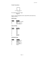
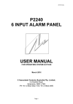
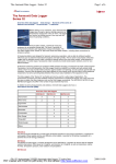
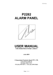
22197-02.doc
P2267
NETWORK INTERFACE
USER MANUAL
FOR OPERATING SYSTEMS:
22031-03
23636-01
October 2009
© Associated Controls (Australia) Pty. Limited
2-4 Norfolk Road
Greenacre, NSW, 2190.
PH +61 2 9642 4922, FAX +61 2 9642 4955
Page 1
22197-02.doc
Table of Contents
1.
2.
3.
4.
Introduction
P2267 Introduction
Differences between firmware 22031-03 and 23636-01
3
3
Unit Description
FRONT PANEL - Main Electronics
Two 7 Segment Displays
Eleven LED’s
Two Pushbuttons
RS232 Serial Port Socket
Relay Outputs
Network Termination Links
Power Connector
Serial Communications Connectors
Network Socket
Mode Links
5
5
5
6
6
6
6
6
6
7
8
Unit Operation
Use of Unit
Monitor Mode
Test Mode
Terminal Mode
System Messages
9
9
10
10
12
Specifications
Specifications
13
Page 2
22197-02.doc
1
Introduction
P2267 INTRODUCTION
The P2267 Network Interface is designed to all the alarm panels on a
network and converts the alarm information into a protocol compatible
with a BMS. The currently supported BMS protocol is ModBus RTU.
Network connection is made directly to the main electronics via an 8
way plug.
Serial Data connection (commonly connected to a BMS) is made
directly to the main electronics via a set of terminal blocks for either
RS232 or RS485/422.
8 programmable relay outputs are available and connection is made
via a set of terminal blocks.
All P2267 programming is done via a 4 pin RS232 plug and socket that
couples it to a computer. This feature permits full custom set up of
Relay Outputs and Active Units.
DIFFERENCES BETWEEN FIRMWARE 22031-03 AND 23636-01
The 23636-01 special version firmware is based on the 22031-03
standard version firmware that is used for all installations. “u1” is
displayed on the P2267 at power up.
The P2267 presents to the BMS system either 9 (P228x) or 25 (P226x)
Holding Registers that show the current status of the Alarm Panel
TIMER (Register 1) and any connected ALARM INPUTS (Register 2 –
9/25). See Section 3 below for all the operational details.
In normal operation, the TIMER will have a value of usually 80 – 90
with the value counting down from 90 until it is reset by the alarm panel
back to 90. The ALARM INPUTS will have a value of 0 for non alarm
and 255 for alarm.
This version of firmware removes the Alarm Panel Global Reset feature
from the P2267. Normally when an alarm panel goes offline any
connected alarm panel with Remote Alarms for the offline panel will
send the panel a reset command. This is standard operation for the
panels.
A typical network using a P2267 will have the alarm panels having only
local alarms with any alarm being repeated through the P2267 to the
BMS system. In this case, the only time a reset command would be
sent was if an alarm panel was having some rather big
Page 3
22197-02.doc
communications problems. The P2267 would receive this command
and reset itself in order to allow the network to stabilise. Upon resetting
the P2267 losses all TIMER register information and the count returns
to 90.
It has been determined that some installations using a P2267 have
alarm panels with both local and remote alarms. This would cause
reset messages to be broadcast if an alarm panel went offline. The
P2267 interprets any reset message as a global message because the
P2267 itself is transparent and is unknown to the alarm panels so it
would reset itself to ensure the network is completely stabilised. This is
an undesired feature in this kind of network.
The 23636-01 revision firmware disables the Alarm Panel Global Reset
feature which allows the TIMER registers to time out down to 0 when
an alarm panel goes offline and this allows the BMS to correctly
interrogate the register.
Associated Controls has tested this network in our factory and can see
no reason why the network would fail due to the P2267 with this
version of firmware.
It is the responsibility of the installer and network maintenance to
understand how the 23636-01 version firmware works so that any
faults can be quickly corrected.
Page 4
22197-02.doc
2
Unit Description
FRONT PANEL - Main Electronics
The main electronics PCB is mounted in a metal enclosure that can be
mounted to any surface.
The front panel presents the operator with the following items:
• Two 7 segment displays.
• Eleven LED’s.
• Two pushbuttons – Network and Test.
Two 7 Segment Displays:
This is used to convey basic information to the operator.
1)
Firmware Revision – at power up, the P2267 will display the
current firmware revision for 2 seconds. “03” or “u1” depending
on the firmware version.
2)
Terminal Mode – when connected to a computer for setup
purposes, the P2267 will display “co” initially until commands are
received from the computer.
3)
File Transmission – when downloading data to the P2267, the
display will show one of six values indicating the current status
of the transfer. (See “Terminal Mode”)
4)
Serial Data Processing – when the P2267 is operating in
Monitor Mode, the two decimal points of the displays act as data
processing indicators. The MSD point indicates successful
incoming data processing, and the LSD point indicates
successful outgoing data processing.
Eleven LED’s:
There are 11 LED’s associated with the panel.
1)
Power LED – Indicates power to the unit is within limits.
2)
Network Data LED – Indicates data on the network.
3)
Service LED – Indicates the network configuration (See the
APM Manual for more information about setting up the network).
4)
Relay Active LED’s – Indicates the activation of one of the eight
relay outputs.
Page 5
22197-02.doc
Two Pushbuttons:
There are two pushbuttons – Test and Network.
1)
Test – Initiates the Test mode from which three options are
available.
2)
Bind – Used to commission the panel into the network.
RS232 SERIAL PORT SOCKET
The RS232 connection is made via a 4 way RJ45 (See Figure 5).
When connected to a computer running “APM” software supplied by
Associated Controls, the operator can configure the P2267 as
required.
RELAY OUTPUTS
There are 8 relays that can be programmed to operating when a
specific panel and alarm number combination occur. Programming of
the relays is done specifically in APM. The connectors to the relays are
on the right hand side of the unit. Each relay has a Common and a
Normally Open and Normally Closed set of contacts. The relays are
energised during the normal operation of the unit and will close the
contacts when power is lost.
NETWORK TERMINATION LINKS
While the network system used by the P2267 is of a “Free Topology”
nature, it still requires one termination on the network. It is not critical
where the termination should be, so long as it is there. Each panel has
the ability to provide the termination, only one on the network is
required. There is a link block beside the 8 way RJ45 connectors
marked as “NETWORK TERMINATION”. To provide termination the
link should be installed, if termination is not required the link should be
left out.
POWER CONNECTOR
Power connection is made using the two way terminal block on the
upper right hand side of the unit.
SERIAL COMMUNICATIONS CONNECTORS
The P2267 offers three types of media for connection to a BMS. The
RS232 mode is not used but is made available for later expansion. The
Page 6
22197-02.doc
other two types are RS485 and RS422 with both Full and Half duplex
modes available. The connectors are located on the left hand side of
the unit.
NETWORK SOCKET
The network connection is made via either one of two 8 way sockets
left hand side. Two sockets are provided, should a “daisy chain” wiring
configuration be required. The system wiring can be of any
configuration as shown if Fig 1 to 4 below, however there are limits on
the cable length. The maximum total wire length in the installation is
450 metres and the maximum distance between any nodes to any
node, or a termination is 250 metres.
The cable length figures above apply to a category 5 UTP solid twisted
pair cable. Only 2 of the 8 ways of the network socket are used at this
stage, (see specifications for pin-outs) 8way is provided for future
expansion.
There is also an 8 way terminal block that presents the network in case
of a twisted pair application but this system is not supported by
Associated Controls as intermittent faults can occur due to cable
tolerances.
Figure 1 Loop Topology
Figure 2 Mixed Topology
Page 7
22197-02.doc
Figure 3 Single Terminated Bus Topology
Figure 4 Star Topology
MODE LINKS
The P2267 has 5 links that are used for configuring the serial
communications modes.
J9 and J10
These two jumpers are used to terminate the serial
communications as required. J10 is selected for half-duplex
communications and both J9 and J10 should be selected for fullduplex communications if required. Terminal of a RS485/422
network should follow the required standards to attain the
greatest compatibility and to minimise noise problems caused by
incorrect terminations and cable impedances.
J11
J11 determines the duplex nature of the communications. When
the jumper is across pins 2 & 3 (the 2 most right pins of the
pinblock) the P2267 will operate in half-duplex mode. When the
jumper is across pins 1 & 2 (the 2 most left pins of the pinblock)
the P2267 will operate in full-duplex mode.
J12 and J13
These two jumpers select the phasing of the twisted pair lines.
The P2267 is set up at the factory for normal phasing (the 2
most left pins are selected), but if it occurs that the lines are
reversed, the two jumpers can be swapped to reversed phasing
(the 2 most right pins are selected).
Page 8
22197-02.doc
3
Unit Operation
USE OF UNIT
From the user point of view there is very little to know. The unit can be
mounted away from every day access as it only transfers data from
one system to another and does not actively contribute to alarm status
or provide useable output from a layman point of view.
The P2267 has four main modes of operation.
MONITOR MODE
The monitor mode is the normal operation of the interface. In this
mode, the panel provides continuous monitoring of the network and
serial communication.
The interface acts as a transparent connector between the ASCON
Alarm Panel Network and the ModBus Network. Each Alarm Panel has
its own Unit ID number (generated in the APM program). The interface
allows the Master ModBus device to access each of the Alarm Panels
as if they existed on the ModBus Network. Each Alarm Panel is
accessed by its Unit ID which becomes its Slave Number. An Alarm
Panel has 25 holding registers which can be interrogated by the
Master. The ModBus Registers that are accessible are the 40000
series 16bit Data Holding Registers.
The following is a list of the available registers:
24 Input
Panel
Reg #
1
2
3
4
5
6
7
8
9
10
11
12
13
14
15
16
Value
Timer
Alarm 1
Alarm 2
Alarm 3
Alarm 4
Alarm 5
Alarm 6
Alarm 7
Alarm 8
Alarm 9
Alarm 10
Alarm 11
Alarm 12
Alarm 13
Alarm 14
Alarm 15
8 Input
Panel
Reg #
1
2
3
4
5
6
7
8
9
10
11
12
13
14
15
16
Page 9
Value
Timer
Alarm 1
Alarm 2
Alarm 3
Alarm 4
Alarm 5
Alarm 6
Alarm 7
Alarm 8
N/A
N/A
N/A
N/A
N/A
N/A
N/A
22197-02.doc
17
18
19
20
21
22
23
24
25
Alarm 16
Alarm 17
Alarm 18
Alarm 19
Alarm 20
Alarm 21
Alarm 22
Alarm 23
Alarm 24
17
18
19
20
21
22
23
24
25
N/A
N/A
N/A
N/A
N/A
N/A
N/A
N/A
N/A
Register #1 is the heartbeat timer for the Alarm Panel. If the Panel is
currently active on the network it heartbeats the network to make sure
that the network is operational. If the interface does not receive a
heartbeat from an allocated panel, the timer will eventually reach zero.
This register can be monitored to make sure that an Alarm Panel is
working correctly. If the register contains a value of $0000
(hexadecimal 0000, decimal 0, 16bit) then the Alarm Panel has not
accessed the network and a problem may be occurring with the Panel.
Registers #2 - #25 are the actual inputs of the Alarm Panel. The
P2262/P2500 uses all 24 registers, while the P2281/P2282 only uses
8. When an input is normal, the register will contain a value of $0000
(hexadecimal 0000, decimal 0, 16bit). When the input is in alarm, the
register will contain a value of $00FF (hexadecimal 00FF, decimal 255,
16bit).
If there are to be several Interface units connecting two or more
ASCON Networks to a ModBus Master, each Panel must have a
unique Unit ID. The system will only support up to 120 Unit ID’s,
remembering that each interface unit will have its own Unit ID.
For example: if there are two networks to be connected to a ModBus
Master and each network has 10 panels, there need to be 2 interface
units which leaves 120 – ((2 x 10) + 2) = 98 Unit ID’s left.
TEST MODE
The test mode is selected by the Test pushbutton. Activating this mode
puts the unit into a test routine that cycles numbers on the two 7
segment displays and then activates each relay one by one. The unit
then returns to Monitor Mode.
TERMINAL MODE
With the exception of those hardware features already described, the
P2267 is configured at installation using “APM” (Alarm Panel
Management) software supplied by Associated Controls. The “APM”
software is run on a suitable computer connected to the P2267
interface via the RS232 socket.
Page 10
22197-02.doc
The “APM” software has its own User Manual giving detailed
instruction on its use. A summary only of the features will be given
here.
The “APM” software has two sections.
1)
File Generation Mode
File generation is the first step in setting up a P2267 panel. It
contains all the allocated relay outputs and all the active units
within the network. It also contains a unique panel ID number
and identification message. The computer need not be
connected to the P2267 at this stage.
This file can be downloaded to a P2267 interface using the
second section “monitor/terminal mode”. No further interface
setup is required if the file information is correct. The
downloading of files into the P2267 should only be done after all
panels have been entered into the project as the active units are
allocated automatically by APM during file generation.
2)
Terminal Mode
The Terminal Mode is used to communicate with the P2267, the
computer must be connected to the P2267 when using this
section.
When the communications cable is connected to the P2267
panel the display will show “co” when the unit is ready to
proceed.
The functions provided in monitor mode are as follows:
Download – used to send a file generated under “File
Generation” to the P2267.
Display Setup – will display the current panel setup information:
Software Revision
Unit / Slave ID
Unit Message ID
Number Of Relay Outputs
Number Of Active Units
Current Baud Rate
Current Media Type
Current Protocol Mode
Current ModBus Type
Page 11
22197-02.doc
SYSTEM MESSAGES
The P2267 has several system messages that can occur when
transferring data from the computer.
“90”
“91”
“92”
“93”
“94”
“95”
Loading File in progress.
File received OK.
EEPROM ERROR – return unit for servicing.
BYTECOUNT ERROR – transfer error, please retry.
CHECKSUM ERROR – transfer error, please retry.
Data saved OK – Please reset unit manually.
Page 12
22197-02.doc
4
Specifications
SPECIFICATIONS
Power Consumption
Operating Voltage
Current Consumption
Power Consumption
12 Volts AC or DC +/- 10%
0.3 Amps
3.6 Watts
Environmental Conditions
Operating Temperature Range
Operating Humidity Range
0 - 45 Deg C
95% R.H. non-condensing
Relay Output
Alarm status relay contact rating
1A @ 30V DC
RS232 PC Communications Serial Output Format
1200 Baud, 8 Bit, 1 Stop, No Parity
RS422/485
Compatible with EIA-422 and EIA-485 standards.
Recommended cable as per standards.
ModBus Format
RTU Mode, 9600 Baud, 1 Start, 8 Data, No Parity, 1 Stop
Network Information
Cable Type
Category 5 UTP solid
Cable Length
Maximum total length in system
Maximum length node to any node or termination
450 metres
250 metres
Network Frequency
78 kbps
Maximum Number of Nodes
30
Page 13
22197-02.doc
Socket Connections
Pin numbering runs left to right
Figure 5
Figure 6 numbering applies to both 4 way RS232 socket and 8 way
Network sockets
RS232 4 Way
Pin No.
1
2
3
4
Function
Common ( Ground )
N/C
TXD ( Data Out )
RXD ( Data In )
Network 8 Way
Pin No.
1
2
3
4
5
6
7
8
Function
N/C
N/C
N/C
N/C
N/C
N/C
Network
Network
RS422/485 6 Way
Pin No.
1
2
3
4
5
6
Function
Full Duplex (+)
Full Duplex (-)
Shield
Half Duplex (+)
Half Duplex (-)
Shield
Page 14