1
3&Y
Installation Guide
WARNING: This manual contains information on limitations regarding product use and function
and information on the limitations as to liability of the manufacturer. The entire manual should
be carefully read.
SAFETY INSTRUCTIONS for SERVICE PERSONNEL
WARNING: When using equipment connected to the TELEPHONE NETWORK, there are basic safety instructions that should
always be followed. Refer to the SAFETY INSTRUCTIONS provided with this product; save them for (future) reference. Instruct the
end-user regarding the safety precautions that shall be observed when operating this equipment.
%HIRUH,QVWDOOLQJ7KH(TXLSPHQW
Ensure your package includes the following items:
• Installation and User Manuals
• PC1404 alarm controller
• Power supply, direct plug-in
• Mounting hardware
READ and SAVE These Instructions!
Follow All WARNINGS AND INSTRUCTIONS specified within this document and/or on the equipment.
6HOHFWLQJ$6XLWDEOH/RFDWLRQ)RU7KH$ODUP&RQWUROOHU
Use the following list as a guide to find a suitable place for this equipment:
• Locate near a telephone socket and power outlet.
• Select a place free from vibration and shocks.
• Place the alarm controller on a flat, stable surface and follow the installation instructions.
DO NOT locate this product where persons may walk on the secondary circuit cable(s).
DO NOT connect the alarm controller to electrical outlets on the same circuit as large appliances.
DO NOT select a place that exposes your alarm controller to direct sunlight, excessive heat, moisture, vapors, chemicals or dust.
DO NOT install this equipment near water. (e.g., bath tub, wash bowl, kitchen/laundry sink, wet basement, near a swimming pool).
DO NOT install this equipment and its accessories in areas where there is a risk of explosion.
DO NOT connect this equipment to electrical outlets controlled by wall switches or automatic timers;
AVOID interference sources.
AVOID setting up the equipment near heaters, air conditioners, ventilators, and/or refrigerators.
AVOID locating this equipment close to or on top of large metal objects (e.g., metal wall studs).
6$)(7<3UHFDXWLRQV5HTXLUHG'XULQJ,QVWDOODWLRQ
• NEVER install this equipment and/or telephone wiring during a lightning storm.
• NEVER touch uninsulated telephone wires or terminals unless the telephone line has been disconnected at the network interface.
• Position cables so that accidents cannot occur. Connected cables must NOT be subject to excessive mechanical strain.
• Use only the power supply provided with this equipment. Use of unauthorized power supplies may cause damage.
• For direct plug-in versions, use the transformer supplied with the device.
WARNING: THIS EQUIPMENT, WHEN POWERED VIA DIRECT PLUG-IN TRANSFORMER, HAS NO MAINS ON/OFF SWITCH.
THE PLUG OF THE DIRECT PLUG-IN POWER SUPPLY IS INTENDED TO SERVE AS THE DISCONNECTING DEVICE IF THE
EQUIPMENT MUST BE QUICKLY DISCONNECTED. IT IS IMPERATIVE THAT ACCESS TO THE MAINS PLUG AND ASSOCIATED MAINS SOCKET/OUTLET IS NEVER OBSTRUCTED.
IMPORTANT NOTE!
7KLV equipment, alarm controller PC1404, VKDOO EH LQVWDOOHG DQG
XVHG ZLWKLQ DQ HQYLURQPHQW WKDW SURYLGHV WKH SROOXWLRQ GHJUHH PD[
DQG RYHUYROWDJHV FDWHJRU\ ,, 121+$=$5'286 /2&$7,216
LQGRRU RQO\ 7KH HTXLSPHQW LV FIXED and 3(50$1(17/< &21
1(&7(' DQG LV GHVLJQHG WR EH LQVWDOOHG VHUYLFHG DQGRU UHSDLUHG
E\ VHUYLFH SHUVRQV RQO\ >VHUYLFH SHUVRQ LV GHILQHG DV D SHUVRQ
KDYLQJ WKH DSSURSULDWH WHFKQLFDO WUDLQLQJ DQG H[SHULHQFH QHFHVVDU\
WR EH DZDUH RI KD]DUGV WR ZKLFK WKDW SHUVRQ PD\ EH H[SRVHG LQ
SHUIRUPLQJ D WDVN DQG RI PHDVXUHV WR PLQLPL]H WKH ULVNV WR WKDW
SHUVRQ RU RWKHU SHUVRQV@ 7KHUH DUH QR SDUWV UHSODFHDEOH E\ WKH
HQGXVHU ZLWKLQ WKLV HTXLSPHQW 7KH ZLULQJ FDEOHV XVHG IRU
LQVWDOODWLRQ RI WKH $ODUP 6\VWHP DQG DFFHVVRULHV VKDOO EH LQVXODWHG
ZLWK39&7)(37)()(31HRSUHQHRU3RO\DPLGH
a) The equipment enclosure must be secured to the building
structure before operation.
b) Internal wiring must be routed in a manner that prevents
- excessive strain or loosening of wire on terminal connections;
- damage of conductor insulation.
c) Disposal of used batteries shall be made in accordance with
local waste recovery and recycling regulations.
d) Before servicing, DISCONNECT the power and telephone
connection.
e) DO NOT route any wiring over circuit boards. Maintain at
least 1” (25.4 mm) separation.
f) It is the installer’s responsibility to ensure that a readily
accessible disconnect device is incorporated in the building for
permanently connected installations.
g) The connection to the mains supply must be made as per
the local authorities’ rules and regulations. An appropriate disconnect device must be provided as part of the building installation. Where it is not possible to rely on identification of the
neutral in the AC Mains supply, the disconnecting device must
disconnect both poles simultaneously (line and neutral). The
device shall disconnect the supply during servicing.
7KH SRZHU VXSSO\ PXVW EH &ODVV ,, )$,/ 6$)( ZLWK GRXEOH RU UHLQIRUFHG LQVXODWLRQ EHWZHHQ WKH 35,0$5< DQG 6(&21'$5< FLUFXLW
(1&/2685(DQGEHDQDSSURYHGW\SHDFFHSWDEOHWRWKHORFDODXWKRULWLHV$OOQDWLRQDOZLULQJUXOHVVKDOOEHREVHUYHG
i
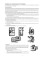
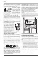
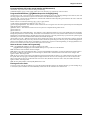
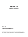
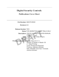
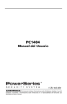
*XLGHOLQHVIRU/RFDWLQJ6PRNH&2'HWHFWRUV
The following information is for general guidance only and it is recommended that local fire codes and regulations be consulted when
locating and installing smoke and CO alarms.
6PRNH'HWHFWRUV
Research indicates that all hostile fires in homes generate smoke to a greater or lesser extent. Detectable quantities of smoke precede
detectable levels of heat in most cases. Smoke alarms should be installed outside of each sleeping area and on each storey of the home.
DSC recommends that additional smoke alarms beyond those required for minimum protection be installed. Additional areas that
should be protected include: the basement; bedrooms, especially where smokers sleep; dining rooms; furnace and utility rooms; and
any hallways not protected by the required units.
On smooth ceilings, detectors may be spaced 9.1m (30 feet) apart as a guide. Other spacing may be required depending on ceiling
height, air movement, the presence of joists, uninsulated ceilings, etc. Consult National Fire Alarm Code NFPA 72, CAN/ULC-S55302 or other appropriate national standards for installation recommendations.
•
Do not locate smoke detectors at the top of peaked or gabled ceilings; dead air space in these locations may prevent smoke detection.
•
Avoid areas with turbulent air flow, such as near doors, fans or windows. Rapid air movement around the detector may prevent
smoke from entering the unit.
•
Do not locate detectors in areas of high humidity.
•
Do not locate detectors in areas where the temperature rises above 38oC (100oF) or falls below 5oC (41oF).
Smoke detectors should always be installed in USA in accordance with Chapter 29 of NFPA 72, the National Fire Alarm Code: 29.5.1.1.
Where required by other governing laws, codes, or standards for a specific type of occupancy, approved single- and multiple-station
smoke alarms shall be installed as follows:
(1) In all sleeping rooms and guest rooms.
(2) Outside of each separate dwelling unit sleeping area, within 21 ft (6.4 m) of any door to a sleeping room, with the distance measured along a path of travel.
(3) On every level of a dwelling unit, including basements.
(4) On every level of a residential board and care occupancy (small facility), including basements and excluding crawl spaces and
unfinished attics.
(5) In the living area(s) of a guest suite.
(6) In the living area(s) of a residential board and care occupancy (small facility).
Figure 3
Figure 2
Figure 1
Figure 4
Figure 3a
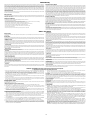
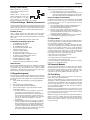
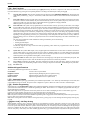
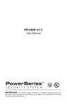
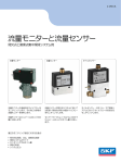
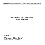
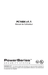
&2'HWHFWRUV
CO gas moves freely in the air. The human body is most vulnerable to the effects of CO gas during
sleeping hours. For maximum protection, a CO alarm should be located outside primary sleeping
areas or on each level of your home. Figure 5 indicates the suggested locations in the home. The
electronic sensor detects carbon monoxide, measures the concentration and sounds a loud alarm
before a potentially harmful level is reached.
Do NOT place the CO alarm in the following areas:
•
Where the temperature may drop below -10ºC or exceed 40 ºC.
•
Near paint thinner fumes.
•
Within 5 feet (1.5 meters) of open flame appliances such as furnaces, stoves and fireplaces.
•
In exhaust streams from gas engines, vents, flues or chimneys.
•
Do not place in close proximity to an automobile exhaust pipe; this will damage the detector.
LL
BEDROOM
BEDROOM
BEDROOM
GROUND
FLOOR
KITCHEN
GARAGE
BASEMENT
CARBON MONOXIDE DETECTOR
Figure 5
Limited Warranty
Digital Security Controls warrants the original purchaser that for a period of twelve months from the date of purchase, the product shall be free of defects in materials and
workmanship under normal use. During the warranty period, Digital Security Controls shall, at its option, repair or replace any defective product upon return of the product to
its factory, at no charge for labour and materials. Any replacement and/or repaired parts are warranted for the remainder of the original warranty or ninety (90) days, whichever
is longer. The original purchaser must promptly notify Digital Security Controls in writing that there is defect in material or workmanship, such written notice to be received in
all events prior to expiration of the warranty period. There is absolutely no warranty on software and all software products are sold as a user license under the terms of the
software license agreement included with the product. The Customer assumes all responsibility for the proper selection, installation, operation and maintenance of any
products purchased from DSC. Custom products are only warranted to the extent that they do not function upon delivery. In such cases, DSC can replace or credit at its option.
International Warranty
The warranty for international customers is the same as for any customer within Canada and the United States, with the exception that Digital Security Controls shall not be
responsible for any customs fees, taxes, or VAT that may be due.
Warranty Procedure
To obtain service under this warranty, please return the item(s) in question to the point of purchase. All authorized distributors and dealers have a warranty program. Anyone
returning goods to Digital Security Controls must first obtain an authorization number. Digital Security Controls will not accept any shipment whatsoever for which prior
authorization has not been obtained.
Conditions to Void Warranty
This warranty applies only to defects in parts and workmanship relating to normal use. It does not cover:
• damage incurred in shipping or handling;
• damage caused by disaster such as fire, flood, wind, earthquake or lightning;
• damage due to causes beyond the control of Digital Security Controls such as excessive voltage, mechanical shock or water damage;
• damage caused by unauthorized attachment, alterations, modifications or foreign objects;
• damage caused by peripherals (unless such peripherals were supplied by Digital Security Controls Ltd.);
• defects caused by failure to provide a suitable installation environment for the products;
• damage caused by use of the products for purposes other than those for which it was designed;
• damage from improper maintenance;
• damage arising out of any other abuse, mishandling or improper application of the products.
Items Not Covered by Warranty
In addition to the items which void the Warranty, the following items shall not be covered by Warranty: (i) freight cost to the repair centre; (ii) products which are not identified
with DSC's product label and lot number or serial number; (iii) products disassembled or repaired in such a manner as to adversely affect performance or prevent adequate
inspection or testing to verify any warranty claim. Access cards or tags returned for replacement under warranty will be credited or replaced at DSC's option. Products not
covered by this warranty, or otherwise out of warranty due to age, misuse, or damage shall be evaluated, and a repair estimate shall be provided. No repair work will be
performed until a valid purchase order is received from the Customer and a Return Merchandise Authorization number (RMA) is issued by DSC's Customer Service.
Digital Security Controls Ltd.’s liability for failure to repair the product under this warranty after a reasonable number of attempts will be limited to a replacement of the product,
as the exclusive remedy for breach of warranty. Under no circumstances shall Digital Security Controls be liable for any special, incidental, or consequential damages based
upon breach of warranty, breach of contract, negligence, strict liability, or any other legal theory. Such damages include, but are not limited to, loss of profits, loss of the
product or any associated equipment, cost of capital, cost of substitute or replacement equipment, facilities or services, down time, purchaser’s time, the claims of third
parties, including customers, and injury to property. The laws of some jurisdictions limit or do not allow the disclaimer of consequential damages. If the laws of such a
jurisdiction apply to any claim by or against DSC, the limitations and disclaimers contained here shall be to the greatest extent permitted by law. Some states do not allow the
exclusion or limitation of incidental or consequential damages, so that the above may not apply to you.
Disclaimer of Warranties
This warranty contains the entire warranty and shall be in lieu of any and all other warranties, whether expressed or implied (including all implied warranties of merchantability
or fitness for a particular purpose) and of all other obligations or liabilities on the part of Digital Security Controls. Digital Security Controls neither assumes responsibility for,
nor authorizes any other person purporting to act on its behalf to modify or to change this warranty, nor to assume for it any other warranty or liability concerning this product.
This disclaimer of warranties and limited warranty are governed by the laws of the province of Ontario, Canada.
WARNING: Digital Security Controls recommends that the entire system be completely tested on a regular basis. However, despite frequent
testing, and due to, but not limited to, criminal tampering or electrical disruption, it is possible for this product to fail to perform as expected.
Out of Warranty Repairs
Digital Security Controls will at its option repair or replace out-of-warranty products which are returned to its factory according to the following conditions. Anyone returning
goods to Digital Security Controls must first obtain an authorization number. Digital Security Controls will not accept any shipment whatsoever for which prior authorization has
not been obtained.
Products which Digital Security Controls determines to be repairable will be repaired and returned. A set fee which Digital Security Controls has predetermined and which may
be revised from time to time, will be charged for each unit repaired.
Products which Digital Security Controls determines not to be repairable will be replaced by the nearest equivalent product available at that time. The current market price of
the replacement product will be charged for each replacement unit.
WARNING - READ CAREFULLY
Note to Installers
This warning contains vital information. As the only individual in contact with system users, it is your responsibility to bring each item in this warning to the attention of the
users of this system.
System Failures
This system has been carefully designed to be as effective as possible. There are circumstances, however, involving fire, burglary, or other types of emergencies where it may
not provide protection. Any alarm system of any type may be compromised deliberately or may fail to operate as expected for a variety of reasons. Some but not all of these
reasons may be:
• Inadequate Installation
A security system must be installed properly in order to provide adequate protection. Every installation should be evaluated by a security professional to ensure that all access
points and areas are covered. Locks and latches on windows and doors must be secure and operate as intended. Windows, doors, walls, ceilings and other building materials
must be of sufficient strength and construction to provide the level of protection expected. A reevaluation must be done during and after any construction activity. An evaluation
by the fire and/or police department is highly recommended if this service is available.
• Criminal Knowledge
This system contains security features which were known to be effective at the time of manufacture. It is possible for persons with criminal intent to develop techniques which
reduce the effectiveness of these features. It is important that a security system be reviewed periodically to ensure that its features remain effective and that it be updated or
replaced if it is found that it does not provide the protection expected.
• Access by Intruders
Intruders may enter through an unprotected access point, circumvent a sensing device, evade detection by moving through an area of insufficient coverage, disconnect a
warning device, or interfere with or prevent the proper operation of the system.
• Power Failure
Control units, intrusion detectors, smoke detectors and many other security devices require an adequate power supply for proper operation. If a device operates from batteries,
it is possible for the batteries to fail. Even if the batteries have not failed, they must be charged, in good condition and installed correctly. If a device operates only by AC power,
any interruption, however brief, will render that device inoperative while it does not have power. Power interruptions of any length are often accompanied by voltage
fluctuations which may damage electronic equipment such as a security system. After a power interruption has occurred, immediately conduct a complete system test to
ensure that the system operates as intended.
• Failure of Replaceable Batteries
This system’s wireless transmitters have been designed to provide several years of battery life under normal conditions. The expected battery life is a function of the device
environment, usage and type. Ambient conditions such as high humidity, high or low temperatures, or large temperature fluctuations may reduce the expected battery life.
While each transmitting device has a low battery monitor which identifies when the batteries need to be replaced, this monitor may fail to operate as expected. Regular testing
and maintenance will keep the system in good operating condition.
• Compromise of Radio Frequency (Wireless) Devices
Signals may not reach the receiver under all circumstances which could include metal objects placed on or near the radio path or deliberate jamming or other inadvertent
radio signal interference.
• System Users
A user may not be able to operate a panic or emergency switch possibly due to permanent or temporary physical disability, inability to reach the device in time, or unfamiliarity
with the correct operation. It is important that all system users be trained in the correct operation of the alarm system and that they know how to respond when the system
indicates an alarm.
• Smoke Detectors
Smoke detectors that are a part of this system may not properly alert occupants of a fire for a number of reasons, some of which follow. The smoke detectors may have been
improperly installed or positioned. Smoke may not be able to reach the smoke detectors, such as when the fire is in a chimney, walls or roofs, or on the other side of closed
doors. Smoke detectors may not detect smoke from fires on another level of the residence or building.
Every fire is different in the amount of smoke produced and the rate of burning. Smoke detectors cannot sense all types of fires equally well. Smoke detectors may not provide
timely warning of fires caused by carelessness or safety hazards such as smoking in bed, violent explosions, escaping gas, improper storage of flammable materials,
overloaded electrical circuits, children playing with matches or arson.
Even if the smoke detector operates as intended, there may be circumstances when there is insufficient warning to allow all occupants to escape in time to avoid injury or death.
• Motion Detectors
Motion detectors can only detect motion within the designated areas as shown in their respective installation instructions. They cannot discriminate between intruders and
intended occupants. Motion detectors do not provide volumetric area protection. They have multiple beams of detection and motion can only be detected in unobstructed
areas covered by these beams. They cannot detect motion which occurs behind walls, ceilings, floor, closed doors, glass partitions, glass doors or windows. Any type of
tampering whether intentional or unintentional such as masking, painting, or spraying of any material on the lenses, mirrors, windows or any other part of the detection system
will impair its proper operation.
Passive infrared motion detectors operate by sensing changes in temperature. However their effectiveness can be reduced when the ambient temperature rises near or above
body temperature or if there are intentional or unintentional sources of heat in or near the detection area. Some of these heat sources could be heaters, radiators, stoves,
barbeques, fireplaces, sunlight, steam vents, lighting and so on.
• Warning Devices
Warning devices such as sirens, bells, horns, or strobes may not warn people or waken someone sleeping if there is an intervening wall or door. If warning devices are located
on a different level of the residence or premise, then it is less likely that the occupants will be alerted or awakened. Audible warning devices may be interfered with by other
noise sources such as stereos, radios, televisions, air conditioners or other appliances, or passing traffic. Audible warning devices, however loud, may not be heard by a
hearing-impaired person.
• Telephone Lines
If telephone lines are used to transmit alarms, they may be out of service or busy for certain periods of time. Also an intruder may cut the telephone line or defeat its operation
by more sophisticated means which may be difficult to detect.
• Insufficient Time
There may be circumstances when the system will operate as intended, yet the occupants will not be protected from the emergency due to their inability to respond to the
warnings in a timely manner. If the system is monitored, the response may not occur in time to protect the occupants or their belongings.
• Component Failure
Although every effort has been made to make this system as reliable as possible, the system may fail to function as intended due to the failure of a component.
• Inadequate Testing
Most problems that would prevent an alarm system from operating as intended can be found by regular testing and maintenance. The complete system should be tested
weekly and immediately after a break-in, an attempted break-in, a fire, a storm, an earthquake, an accident, or any kind of construction activity inside or outside the premises.
The testing should include all sensing devices, keypads, consoles, alarm indicating devices and any other operational devices that are part of the system.
•Security and Insurance
Regardless of its capabilities, an alarm system is not a substitute for property or life insurance. An alarm system also is not a substitute for property owners, renters, or other
occupants to act prudently to prevent or minimize the harmful effects of an emergency situation.
IMPORTANT - READ CAREFULLY: DSC Software purchased with or without Products and Components
is copyrighted and is purchased under the following license terms:
• This End-User License Agreement (“EULA”) is a legal agreement between You (the company, individual or entity who acquired the Software and any
related Hardware) and Digital Security Controls, a division of Tyco Safety Products Canada Ltd. (“DSC”), the manufacturer of the integrated security
systems and the developer of the software and any related products or components (“HARDWARE”) which You acquired.
• If the DSC software product (“SOFTWARE PRODUCT” or “SOFTWARE”) is intended to be accompanied by HARDWARE, and is NOT accompanied by
new HARDWARE, You may not use, copy or install the SOFTWARE PRODUCT. The SOFTWARE PRODUCT includes computer software, and may
include associated media, printed materials, and “online” or electronic documentation.
• Any software provided along with the SOFTWARE PRODUCT that is associated with a separate end-user license agreement is licensed to You under the
terms of that license agreement.
• By installing, copying, downloading, storing, accessing or otherwise using the SOFTWARE PRODUCT, You agree unconditionally to be bound by the
terms of this EULA, even if this EULA is deemed to be a modification of any previous arrangement or contract. If You do not agree to the terms of this
EULA, DSC is unwilling to license the SOFTWARE PRODUCT to You, and You have no right to use it.
SOFTWARE PRODUCT LICENSE
The SOFTWARE PRODUCT is protected by copyright laws and international copyright treaties, as well as other intellectual property laws and treaties. The
SOFTWARE PRODUCT is licensed, not sold.
1.GRANT OF LICENSE This EULA grants You the following rights:
(a) Software Installation and Use - For each license You acquire, You may have only one copy of the SOFTWARE PRODUCT installed.
(b) Storage/Network Use - The SOFTWARE PRODUCT may not be installed, accessed, displayed, run, shared or used concurrently on or from different
computers, including a workstation, terminal or other digital electronic device (“Device”). In other words, if You have several workstations, You will
have to acquire a license for each workstation where the SOFTWARE will be used.
(c) Backup Copy - You may make back-up copies of the SOFTWARE PRODUCT, but You may only have one copy per license installed at any given time.
You may use the back-up copy solely for archival purposes. Except as expressly provided in this EULA, You may not otherwise make copies of the
SOFTWARE PRODUCT, including the printed materials accompanying the SOFTWARE.
2. DESCRIPTION OF OTHER RIGHTS AND LIMITATIONS
(a) Limitations on Reverse Engineering, Decompilation and Disassembly - You may not reverse engineer, decompile, or disassemble the SOFTWARE
PRODUCT, except and only to the extent that such activity is expressly permitted by applicable law notwithstanding this limitation. You may not make any
changes or modifications to the Software, without the written permission of an officer of DSC. You may not remove any proprietary notices, marks or
labels from the Software Product. You shall institute reasonable measures to ensure compliance with the terms and conditions of this EULA.
(b) Separation of Components - The SOFTWARE PRODUCT is licensed as a single product. Its component parts may not be separated for use on more
than one HARDWARE unit.
(c) Single INTEGRATED PRODUCT - If You acquired this SOFTWARE with HARDWARE, then the SOFTWARE PRODUCT is licensed with the HARDWARE
as a single integrated product. In this case, the SOFTWARE PRODUCT may only be used with the HARDWARE as set forth in this EULA.
(d) Rental - You may not rent, lease or lend the SOFTWARE PRODUCT. You may not make it available to others or post it on a server or web site.
(e) Software Product Transfer - You may transfer all of Your rights under this EULA only as part of a permanent sale or transfer of the HARDWARE,
provided You retain no copies, You transfer all of the SOFTWARE PRODUCT (including all component parts, the media and printed materials, any
upgrades and this EULA), and provided the recipient agrees to the terms of this EULA. If the SOFTWARE PRODUCT is an upgrade, any transfer must
also include all prior versions of the SOFTWARE PRODUCT.
(f) Termination - Without prejudice to any other rights, DSC may terminate this EULA if You fail to comply with the terms and conditions of this EULA.
In such event, You must destroy all copies of the SOFTWARE PRODUCT and all of its component parts.
(g) Trademarks - This EULA does not grant You any rights in connection with any trademarks or service marks of DSC or its suppliers.
3. COPYRIGHT - All title and intellectual property rights in and to the SOFTWARE PRODUCT (including but not limited to any images, photographs, and
text incorporated into the SOFTWARE PRODUCT), the accompanying printed materials, and any copies of the SOFTWARE PRODUCT, are owned by DSC
or its suppliers. You may not copy the printed materials accompanying the SOFTWARE PRODUCT. All title and intellectual property rights in and to the
content which may be accessed through use of the SOFTWARE PRODUCT are the property of the respective content owner and may be protected by
applicable copyright or other intellectual property laws and treaties. This EULA grants You no rights to use such content. All rights not expressly granted
under this EULA are reserved by DSC and its suppliers.
4. EXPORT RESTRICTIONS - You agree that You will not export or re-export the SOFTWARE PRODUCT to any country, person, or entity subject to
Canadian export restrictions.
5. CHOICE OF LAW - This Software License Agreement is governed by the laws of the Province of Ontario, Canada.
6. ARBITRATION - All disputes arising in connection with this Agreement shall be determined by final and binding arbitration in accordance with the
Arbitration Act, and the parties agree to be bound by the arbitrator’s decision. The place of arbitration shall be Toronto, Canada, and the language of the
arbitration shall be English.
7. LIMITED WARRANTY
(a) NO WARRANTY - DSC PROVIDES THE SOFTWARE “AS IS” WITHOUT WARRANTY. DSC DOES NOT WARRANT THAT THE SOFTWARE WILL MEET YOUR
REQUIREMENTS OR THAT OPERATION OF THE SOFTWARE WILL BE UNINTERRUPTED OR ERROR-FREE.
(b) CHANGES IN OPERATING ENVIRONMENT - DSC shall not be responsible for problems caused by changes in the operating characteristics of the
HARDWARE, or for problems in the interaction of the SOFTWARE PRODUCT with non-DSC-SOFTWARE or HARDWARE PRODUCTS.
(c) LIMITATION OF LIABILITY; WARRANTY REFLECTS ALLOCATION OF RISK - IN ANY EVENT, IF ANY STATUTE IMPLIES WARRANTIES OR CONDITIONS
NOT STATED IN THIS LICENSE AGREEMENT, DSC’S ENTIRE LIABILITY UNDER ANY PROVISION OF THIS LICENSE AGREEMENT SHALL BE LIMITED
TO THE GREATER OF THE AMOUNT ACTUALLY PAID BY YOU TO LICENSE THE SOFTWARE PRODUCT AND FIVE CANADIAN DOLLARS (CAD$5.00).
BECAUSE SOME JURISDICTIONS DO NOT ALLOW THE EXCLUSION OR LIMITATION OF LIABILITY FOR CONSEQUENTIAL OR INCIDENTAL
DAMAGES, THE ABOVE LIMITATION MAY NOT APPLY TO YOU.
(d) DISCLAIMER OF WARRANTIES - THIS WARRANTY CONTAINS THE ENTIRE WARRANTY AND SHALL BE IN LIEU OF ANY AND ALL OTHER
WARRANTIES, WHETHER EXPRESSED OR IMPLIED (INCLUDING ALL IMPLIED WARRANTIES OF MERCHANTABILITY OR FITNESS FOR A
PARTICULAR PURPOSE) AND OF ALL OTHER OBLIGATIONS OR LIABILITIES ON THE PART OF DSC. DSC MAKES NO OTHER WARRANTIES. DSC
NEITHER ASSUMES NOR AUTHORIZES ANY OTHER PERSON PURPORTING TO ACT ON ITS BEHALF TO MODIFY OR TO CHANGE THIS WARRANTY,
NOR TO ASSUME FOR IT ANY OTHER WARRANTY OR LIABILITY CONCERNING THIS SOFTWARE PRODUCT.
(e) EXCLUSIVE REMEDY AND LIMITATION OF WARRANTY - UNDER NO CIRCUMSTANCES SHALL DSC BE LIABLE FOR ANY SPECIAL, INCIDENTAL,
CONSEQUENTIAL OR INDIRECT DAMAGES BASED UPON BREACH OF WARRANTY, BREACH OF CONTRACT, NEGLIGENCE, STRICT LIABILITY, OR
ANY OTHER LEGAL THEORY. SUCH DAMAGES INCLUDE, BUT ARE NOT LIMITED TO, LOSS OF PROFITS, LOSS OF THE SOFTWARE PRODUCT OR
ANY ASSOCIATED EQUIPMENT, COST OF CAPITAL, COST OF SUBSTITUTE OR REPLACEMENT EQUIPMENT, FACILITIES OR SERVICES, DOWN
TIME, PURCHASERS TIME, THE CLAIMS OF THIRD PARTIES, INCLUDING CUSTOMERS, AND INJURY TO PROPERTY.
WARNING: DSC recommends that the entire system be completely tested on a regular basis. However, despite frequent testing, and due to,
but not limited to, criminal tampering or electrical disruption, it is possible for this SOFTWARE PRODUCT to fail to perform as expected.
LLL
Table of Contents
SAFETY INSTRUCTIONS for SERVICE PERSONNEL . . . . . . . . . . . . . . . . . . . . . . . . . . . . . . . . . . . . . ii
1 Introduction . . . . . . . . . . . . . . . . . . . . . . . . . . . . . . . . . . . . . . . . . . . . . . . . . . . . . . . . . . . . . . . . . . . . . . . . 1
1.1 Compatibility Requirements . . . . . . . . . . . . . . . . . . . . . . . . . . . . . . . . . . . . . . . . . . . . . . . . . . . . . . . . . . 1
1.2 Product Specifications . . . . . . . . . . . . . . . . . . . . . . . . . . . . . . . . . . . . . . . . . . . . . . . . . . . . . . . . . . . . . . 1
1.3 Out of the Box. . . . . . . . . . . . . . . . . . . . . . . . . . . . . . . . . . . . . . . . . . . . . . . . . . . . . . . . . . . . . . . . . . . . . 2
2 Installation . . . . . . . . . . . . . . . . . . . . . . . . . . . . . . . . . . . . . . . . . . . . . . . . . . . . . . . . . . . . . . . . . . . . . . . . . 3
2.1 Installation Steps. . . . . . . . . . . . . . . . . . . . . . . . . . . . . . . . . . . . . . . . . . . . . . . . . . . . . . . . . . . . . . . . . . . 3
2.2 Terminal Descriptions. . . . . . . . . . . . . . . . . . . . . . . . . . . . . . . . . . . . . . . . . . . . . . . . . . . . . . . . . . . . . . . 3
2.3 Wire Routing for Power & Non-Power Limited. . . . . . . . . . . . . . . . . . . . . . . . . . . . . . . . . . . . . . . . . . . 4
2.4 Keybus Operation and Wiring . . . . . . . . . . . . . . . . . . . . . . . . . . . . . . . . . . . . . . . . . . . . . . . . . . . . . . . . 4
2.5 Current Ratings – Modules & Accessories . . . . . . . . . . . . . . . . . . . . . . . . . . . . . . . . . . . . . . . . . . . . . . 5
2.6 Keypad Assignment . . . . . . . . . . . . . . . . . . . . . . . . . . . . . . . . . . . . . . . . . . . . . . . . . . . . . . . . . . . . . . . . 5
2.7 Supervision . . . . . . . . . . . . . . . . . . . . . . . . . . . . . . . . . . . . . . . . . . . . . . . . . . . . . . . . . . . . . . . . . . . . . . . 5
2.8 Removing Modules. . . . . . . . . . . . . . . . . . . . . . . . . . . . . . . . . . . . . . . . . . . . . . . . . . . . . . . . . . . . . . . . . 5
2.9 Zone Wiring . . . . . . . . . . . . . . . . . . . . . . . . . . . . . . . . . . . . . . . . . . . . . . . . . . . . . . . . . . . . . . . . . . . . . . 5
2.10 Zone Doubling . . . . . . . . . . . . . . . . . . . . . . . . . . . . . . . . . . . . . . . . . . . . . . . . . . . . . . . . . . . . . . . . . . . 6
2.11 Fire Zone Wiring . . . . . . . . . . . . . . . . . . . . . . . . . . . . . . . . . . . . . . . . . . . . . . . . . . . . . . . . . . . . . . . . . 7
2.12 CO Detector Wiring . . . . . . . . . . . . . . . . . . . . . . . . . . . . . . . . . . . . . . . . . . . . . . . . . . . . . . . . . . . . . . . 7
2.13 Keypad Zones . . . . . . . . . . . . . . . . . . . . . . . . . . . . . . . . . . . . . . . . . . . . . . . . . . . . . . . . . . . . . . . . . . . 7
3 Keypad Commands . . . . . . . . . . . . . . . . . . . . . . . . . . . . . . . . . . . . . . . . . . . . . . . . . . . . . . . . . . . . . . . . . 10
3.1 Arming and Disarming . . . . . . . . . . . . . . . . . . . . . . . . . . . . . . . . . . . . . . . . . . . . . . . . . . . . . . . . . . . . 10
3.2 Auto Bypass – Stay Arming . . . . . . . . . . . . . . . . . . . . . . . . . . . . . . . . . . . . . . . . . . . . . . . . . . . . . . . . 10
3.3 Automatic Arming . . . . . . . . . . . . . . . . . . . . . . . . . . . . . . . . . . . . . . . . . . . . . . . . . . . . . . . . . . . . . . . . 10
3.4 Night Arming . . . . . . . . . . . . . . . . . . . . . . . . . . . . . . . . . . . . . . . . . . . . . . . . . . . . . . . . . . . . . . . . . . . . 10
3.5 [*] Commands . . . . . . . . . . . . . . . . . . . . . . . . . . . . . . . . . . . . . . . . . . . . . . . . . . . . . . . . . . . . . . . . . . . 10
4 Programming . . . . . . . . . . . . . . . . . . . . . . . . . . . . . . . . . . . . . . . . . . . . . . . . . . . . . . . . . . . . . . . . . . . . . . 16
4.1 Installer Programming . . . . . . . . . . . . . . . . . . . . . . . . . . . . . . . . . . . . . . . . . . . . . . . . . . . . . . . . . . . . . 16
4.2 Programming Decimal Data . . . . . . . . . . . . . . . . . . . . . . . . . . . . . . . . . . . . . . . . . . . . . . . . . . . . . . . . 16
4.3 Programming HEX Data . . . . . . . . . . . . . . . . . . . . . . . . . . . . . . . . . . . . . . . . . . . . . . . . . . . . . . . . . . . 16
4.4 Programming Toggle Option Selections . . . . . . . . . . . . . . . . . . . . . . . . . . . . . . . . . . . . . . . . . . . . . . . 17
4.5 Viewing Programming . . . . . . . . . . . . . . . . . . . . . . . . . . . . . . . . . . . . . . . . . . . . . . . . . . . . . . . . . . . . . 17
4.6 DLS Programming . . . . . . . . . . . . . . . . . . . . . . . . . . . . . . . . . . . . . . . . . . . . . . . . . . . . . . . . . . . . . . . . 17
5 Programming Worksheets . . . . . . . . . . . . . . . . . . . . . . . . . . . . . . . . . . . . . . . . . . . . . . . . . . . . . . . . . . . . 18
5.1 Index to Programming Worksheets . . . . . . . . . . . . . . . . . . . . . . . . . . . . . . . . . . . . . . . . . . . . . . . . . . . 18
5.2 Programming Worksheets . . . . . . . . . . . . . . . . . . . . . . . . . . . . . . . . . . . . . . . . . . . . . . . . . . . . . . . . . . 19
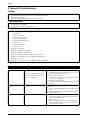
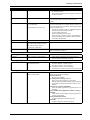
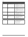
6 Testing & Troubleshooting . . . . . . . . . . . . . . . . . . . . . . . . . . . . . . . . . . . . . . . . . . . . . . . . . . . . . . . . . . . 34
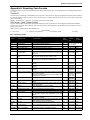
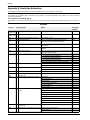
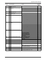
Appendix A: Reporting Code Formats . . . . . . . . . . . . . . . . . . . . . . . . . . . . . . . . . . . . . . . . . . . . . . . . . . . 37
Appendix B: Communicator Format Options . . . . . . . . . . . . . . . . . . . . . . . . . . . . . . . . . . . . . . . . . . . . . . 40
Appendix C: Regulatory Approvals Information . . . . . . . . . . . . . . . . . . . . . . . . . . . . . . . . . . . . . . . . . . . 42
Appendix D: New Zealand Addendum . . . . . . . . . . . . . . . . . . . . . . . . . . . . . . . . . . . . . . . . . . . . . . . . . . . 45
Appendix E: Australian Addendum . . . . . . . . . . . . . . . . . . . . . . . . . . . . . . . . . . . . . . . . . . . . . . . . . . . . . . 46
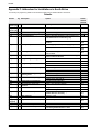
Appendix F: Addendum for Installations in South Africa . . . . . . . . . . . . . . . . . . . . . . . . . . . . . . . . . . . . . 48
iv
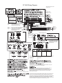
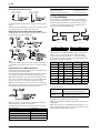
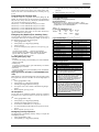
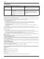
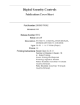
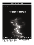
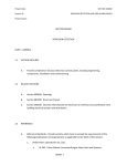
PC1404 Wiring Diagram
Test the alarm system at least
once per week.
so sI
UL
.
SIA-FAR Minimum System
Requirements:
1 PC1404 Panel
1 Local annunciation devices
Applicable UL Standards
UL 985 Household Fire Warning System Units
UL1023 Household Burglar Alarm System Units
UL 1635 Digital Alarm Communicator System Units
ANSI/SIA CP-01-2010
Battery capacity for 4 h standby is
at least 4 Ah. Battery capacity for 24 h
standby is 7 Ah. (Max. Aux current shall
be in accordance with Section 2.2 battery
connection.) Recommended batteries:
DSC BD4-12 or DSC BD7-12.
For NA
installations
only
-
Local annunciation devices may be
any combination of these keypads:
PK5500, PK5501, PK5508, PK5516,
PC1404RKZ, LCD5511, LED5511Z,
PC1555RKZ
AUX Wiring
Use No. 14-22 AWG conductor.
Total current draw from keypads,
PGM outputs and AUX circuits must
not exceed 550mA.
-
4.0/7.0 Ah
CON1
BAT+BAT-
200–350 mA
RED
BLK
T-1
R-1
TIP
RING
Use a UL/CSA-listed Class 2 Transformer
16.5VAC 40 VA DSC PTD 1640U (USA)/
PTD 1640 (CDN).
(NA)
DO not connect transformer to
receptacle controlled by a switch.
BRN
Telephone line wiring
GRA
GRN
RED
RJ-31X
26 AWG
30
REFER TO
MANUAL FOR
LIST OF
COMPATIBLE
DEVICES
Note: It is the installer’s responsibility to (EU) 230/240 VAC
For EU
50/60Hz
installations ensure that the external PRIMARY wires
are tied together using a cable tie or
only
FUSE
315mA/250V
equivalent as close as possible
(within terminal block)
to the terminal block.
LCD5511
LED5511
PC1555RKZ
PK5500/PK5501
PK5508/PK5516
PC1404RKZ
2-WIRE SMOKE DETECTORS
PC14-1
13.7
24
2200 Ohm
END-OF-LINE
RESISTOR
EOLR-3
COMPATIBILITY ID MAX #
BASE
NAME MODEL
SEE NOTE NONE
DSC
FSA-210B Series FS200
NOTE: Refer to the FSA-210 Installation Manual for more details.
o
.
4-WIRE SMOKE DETECTORS
RM-1/RM-2 POWER LOOP
SUPERVISORY RELAY
UL compatibility ID for FSA-210B
series is FS200; for ULC listed
installations, use FSA-210A and
FSA-410A series.
12VDC
ALARM
INITIATING
LOOP
RESISTANCE
100 Ohm
EOLR-2
END-OF-LINE
RESISTOR
5600 Ohm, 0.5W
ZONE DOUBLING
1500
RED
YELLOW
RED
GOLD
BROWN
GREEN
RED
GOLD
2400
(a) The delay (power-up) time marked on the installation wiring diagram of the smoke detector
or on the installed smoke detector(s) is to be used. Control panel is suitable for the following
UL installations:
Installation Type
Signalling Means
Resi Fire Burg
DACT
US: F53AL01BPC1404
IC:160A-PC1404
-31X
In Canada, the PC1404 is listed for Residential Fire and Burglary installations. The product
shall be installed as per UL-S540 and ULC-S310 Standards.
(32-120 F) (for UL/ULC applications)
0 -49
85
Refer to the Installation Guide (29008503) and User Manual (29008622) for complete
operating instructions.
1404 is UL listed
WARNING: Incorrect connection of batteries may result in battery rupture or
fire hazard. Do NOT allow metal objects to connect the positive and
negative terminals. Ensure that batteries are connected with correct polarity
[Red to (+), Black to (-)]. Failure to comply with this may result in battery
rupture and/or fire hazard.
THIS UNIT INCLUDES AN ALARM VERIFICATION FEATURE THAT WILL RESULT IN A
DELAY OF THE SYSTEM ALARM SIGNAL FROM THE INDICATED CIRCUITS. THE
TOTAL DELAY (CONTROL UNIT PLUS SMOKE DETECTORS) SHALL NOT EXCEED 60
SECONDS. NO OTHER SMOKE DETECTOR SHALL BE CONNECTED TO THESE
CIRCUITS UNLESS APPROVED BY THE LOCAL AUTHORITY HAVING JURISDICTION.
Note: Alarm Verification is not supported for 2-wire interface, only 4-wire.
v
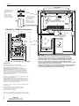
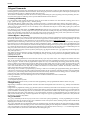
3&
North America Only
POWER LIMITED
Stand Off
PC Board
Cable Tie (not supplied) recommended
Cabinet
2. Position circuit board
mounting holes over
standoffs. Press firmly
on board to snap-in-place.
DSC
UA503
Primar y:120VAC/60Hz.
Secondar y: 16.5VAC 40VA
DSCPTD 1640U
Class II Transformer
PC1404
220
1. Inser t Stand off into cabinet
mounting hole in the
desired location. Snap-inplace.
WARNING:
NOTE: Do not connect
transformer to receptacle
controlled by a switch
High Voltage. Disconnect AC Power
and telephone lines before servicing
CON1
BAT+BATAC AC
AUX+
BELL+
PGM1
AUXBELL- RED BLK YEL GRN
PGM2 Z1 COM Z2
RING
Z3 COM Z4 EGND
TIP R1
T1
230/240 VAC 50/60 Hz International
suggested GND point
See ground wiring
diagram on page v
of this manual
CON1
BAT+BATAC AC
12V / 4 or 7 AHr
To EGND
Terminal
BLACK
16.5VAC/40VA
RED
NON-POWER LIMITED
DSC Model BD7-12
or equivalent
FUSE
WARNING: Incorrect connections may result in PTC failure or improper operation.
Inspect wiring and ensure connections are correct before applying power.
Incorrect connection of batteries may result in battery rupture or Fire Hazard.
Do NOT allow metal objects to connect the Positive and Negative Terminals.
Ensure that batteries are connected with correct polarity [Red to (+), Black to (-)].
Failure to comply with this may result in battery rupture and/or Fire Hazard.
All circuits are classified for UL Installations as Power Limited/Class II Power Limited
except for battery leads which are not power limited.
IMPORTANT:
a)This equipment, Alarm Controller PC1404 shall
be installed and used within an environment that provides the
pollution degree max 2 and over voltages category II
NON-HAZARDOUS LOCATIONS, indoor only. The equipment is
FIXED and PERMANENTLY connected and is designed to be
installed by ser vice persons only; [service person is defined as a
person having the appropriate technical training and experience
necessary to be aware of hazards to which that person may be
exposed in performing a task and of measures to minimize the risks
to that person or other persons.]
Do NOT route any wiring over circuit boards. Maintain at least 1"(25.4mm) separation.
A minimum of 1/4" (6.4mm) separation must be maintained at all points between
power limited wiring and all other non-power limited wiring.
b)The connection to the mains supply must be made as per the local
authorities rules and regulations.
An appropriate disconnect device must be provided as par t of the
building installation. Where it is not possible to rely on identification of
the neutral in the AC Mains supply the disconnecting device must
disconnect both poles simultaneously (line and neutral). The device
shall disconnect the supply during servicing.
c)The equipment enclosure must be secured to the building structure
before operation.
e)Internal wiring must be routed in a manner that prevents:
- Excessive strain on wire and on terminal connections;
- Loosening of terminal; connections;
- Damage of conductor insulation
DG009606
f) Disposal of the used batteries shall be made according to the waste
recovery and recycling regulations applicable to the intended market.
WARNING:
High Voltage. Disconnect AC Power
and telephone lines before servicing
vi
1 Introduction
1 Introduction
This manual provides installation and programming information for the PC1404 four-zone panel security system.
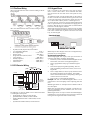
1.1 Compatibility Requirements
The PC1404 product is the central component of the four-zone security system. Interaction with associated system devices is hardwired,
which follows DSC keybus standards. Communications with the central station may be achieved by a hardwired phone line. DLS may
also be remotely connected to the panel via phone line or locally connected via the PC-Link header. Shown below are the supported and
unsupported modules for the PC1404.
Note: All necessary information required to meet UL listing requirements is included in this document.
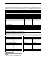
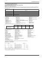
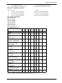
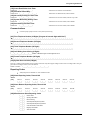
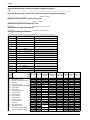
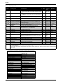
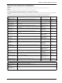
7DEOH6XSSRUWHG0RGXOHV
Module
Current Draw, mA
Software Versions
PC1404RKZ Keypad*
120
1.0
PK5500/PK5501/PK5508/PK5516 Keypads*
125
1.0, 1.1, 1.2, 1.3
LCD5511 Fixed Message LCD Keypad*
85
1.0
LED5511 8-Zone LED Keypad*
100
1.0
PC1555RKZ 8-Zone LED Keypad*
85
2.0
PC5200 Power Supply*
20
2.0
PC5204 Power Supply with 4 PGMs*
20
2.0
PC5208 Low Current PGM Module*
20
1.0
PC5601 LED Status Module
30
1.0
TL300 T-Link TL300 IP Alarm Communicator*
360
1.2-1.5
GS3060 GPRS Universal Cellular Alarm Communicator*
120
3.1, 3.2
3G3070 HSPA (3G) Universal Cellular Alarm Communicator*
120
3.5
GS3105/3125-K & BA Wireless Alarm Communicator
250 (excluding outputs)
3.0
*UL/ULC-listed devices.
Note: For UL/ULC-listed installations, use only UL/ULC-listed devices.
Note: For SIA CP-01: 2010 compliant installations, the minimum required components are: PC1404 Control Panel and PC1404RKZ
keypad. Optional components that can be used with the system are: PK55XX series keypad. These keypads can only be used for SIA
CP-01: 2010 Compliant installations if the emergency keys are not enabled.
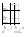
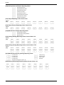
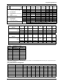
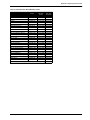
7DEOH8QVXSSRUWHG0RGXOHV
Module
7DEOH&RPSDWLEOH6PRNH'HWHFWRU0RGHOV
4-Wire Smoke Detectors
2-Wire Smoke Detectors
PC5100 2-wire interface
PC5964 Large Audio Station
FSA-410x
FSA-210x
RFK55XX Keypad
PC5401 RS232 Module
FSA-410xT
FSA-210xT
RF5132-433 Wireless Receiver
PC5400 Printer + DVACS
FSA-410xS
FSA-210xS
RF5108-433 Wireless Receiver
Escort 5580 Telephone
Interface
FSA-410xST
FSA-210xST
PC5108 Zone Expander
TL260 Series Communicators
FSA-410xLST
FSA-210xLST
PC5320 Zone Expander
GS2060
Series
Wireless
Alarm Communicator
FSA-410xR
FSA-210xR
PC5950 Audio Module
TL250 Communicator
FSA-410xRT
FSA-210xRT
PC5904 Large Audio Station
TL150 Communicator
FSA-410xRS
FSA-210xRS
PC5921 Audio Station
IT100 Integration Module
FSA-410xRST
FSA-210xRST
PC5961, PC5962 Small Audio
Station
IT120 Integration Module
FSA-410xLRST
FSA-210xLRST
PTK5507 Touchscreen keypad
Note: For model numbers above, x = A (ULC); x = B (UL); x = C (CE)
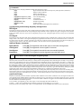
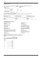
1.2 Product Specifications
Control and Indicating Equipment Specifications
Features
• Supports zone doubling — supervised and distinguishable
• NC/Single/Double EOL support
1
PC1404
•
•
•
•
•
•
•
Supports up to 4 keypads
1 Partition support
128 events
Communications: on-board PSTN
4 phone numbers
2-wire and 4-wire smoke detector support
Auto-arming
Keybus Terminals
• Clock: yellow
• Data: green
Memory
Zone Configuration
• 32Kbit serial CMOS EEPROM with write protection
• Retains programming and system status on AC or battery failure
• Data retention: 20 years min.
• 31 zone types and 11 programmable zone attributes
• Supports up to 4 hardwired NC, SEOL, DEOL zones, expandable to 8 with the zone doubling feature
• Keypad zones allow the system to be configured to support 8
zones—4 onboard zones and up to 4 keypad zones
Bell Output
• 12V, 700mA supervised (1k) bell output (current limited at 2A)
• Steady (for burglary), pulsed or temporal three (for Fire),
temporal four (for CO) alarm cadences supported
• Bell short detection
Access Codes
Operating Environmental Conditions
• Supports 39 user codes and 1 master code
• 6 programmable user code attributes; see PC1404 User Manual for details
• Duress codes derived from user codes ± 1 digit are not allowed
• Temperature range: 0°C to 49°C (32°F-120°F)
• Relative humidity: 85% noncondensing
Telco Terminals
Ring
Tip
Programmable Outputs (PGMs)
• Up to an additional 12 PGMs are supported with PGM
expander for a total of 14 PGMs on the system
• 24 PGM types
• PGM 1: 50mA switched
• PGM 2: 300mA current-limited switched. This PGM supports
compatible 2-wire smoke detectors (90mA current limited)
Power Supply
• 1.5A regulated
• Panel current draw:
240 VAC Primary...............................180 mA(AC)(Max.)
120 VAC Primary...............................330 mA(AC)(Max.)
16.5 VAC Secondary..........................1.5A(AC)(Max.)
• Nominal panel current draw: 85mA
• 550mA Auxiliary Supply, 11.1-12.5VDC (12VDC nominal)
• Positive Temperature Coefficient (PTC) for BELL, AUX+
and battery terminals
• Reverse Battery Detection/Protection
• Supervision for loss of AC power and low battery
• Output ripple voltage 85mV p-p (Max.)
Power Requirements
• AC Transformer Requirements:
Primary = 120VAC, 50/60Hz, 0.33A
Secondary = 16.5VAC, 40VA (North American market)
DSC PTD1640U (UL); DSC PTC1640 (ULC).
Primary = 230/240VAC, 50/60Hz, 0.21A
Secondary = 16.5VAC, 40VA (Australian, South African,
International markets)
• Transformers must be Energy Efficient as per the local rules
and regulations
• High-efficiency transformer for Australia
Battery
•
•
•
•
•
•
•
•
•
12V sealed lead acid battery
Charging mechanism supports 4Ah, 7Ah batteries
Charging rate: 240mA (12 hrs Max.)
Range for the charge current: 200mA–350mA
Backup time: 24 hrs (use 7Ah battery) or 4 hrs (use 4Ah battery)
Replace battery every 3–5 years.
Low battery trouble indication threshold 11.25VDC
Low battery trouble restore threshold 11.75VDC
Battery deep discharge protection: fixed at 9.6V
Aux+:
• Voltage: 11.1–12.5VDC
• Current: 550mA (Max.)
Note: Aux and PGM outputs share the 550mA load.
2
R-1
T-1
• Ring detection: 30V RMS min
• Protection for high ring voltage - Sidactor
PCB Dimensions
• Length: 153 mm (6.0")
• Width: 94 mm (3.7")
• Height (tallest component): 28 mm (1.1")
System Supervision Features
The PC1404 continuously monitors a number of possible trouble
conditions and provides audible and visual indication at the keypad. Trouble conditions include:
• AC Power Failure
• Fire Trouble
• Telephone Line Trouble
• Low Battery Condition
• Bell Circuit Trouble
• General System Trouble (indicates peripheral module trouble)
• General System Tamper (indicates peripheral module tamper)
• Loss of System Time
• Tamper by Zone
• Failure to Communicate
False Alarm Prevention Features
•
•
•
•
•
•
•
Audible Exit Delay
Audible Exit Fault
Communication Delay
Entry Delay Urgency
Quick Exit
Cross Zone Burglary Alarm
Rotating Keypress Buffer
Cabinets
Several cabinets are available for the PC1404, as follows:
PC5003C Cabinet
Cabinet for the PC1404 alarm controller. Dimensions (approximate):
288mm x 298mm x 78mm/11.3"x 11.7" x 3"
PC500C Cabinet Household Fire and Burglary
Cabinet for the PC1404 alarm controller. Dimensions (approximate):
213mm x 235mm x 78mm/8.4" x 9.25" x 3.0"
1.3 Out of the Box
Verify that the following components are included in your system:
•
•
•
•
•
one PC500C cabinet
one PC1404 main control circuit board
one Installation Manual with programming worksheets
one PC1404 Quick Reference Guide
one hardware pack consisting of:
–one 2-wire battery harness; L=34cm black & red
–four 3/8" nylon standoffs; locking PCB support
–eight 5600 (5.6K) 1/2W 5%TR resistors
–eight 1500 (1.5K) 1/2W 5%TR resistors
–four 2400W5%TR resistors
–one 2200W5%TR resistor
–one 1000W5%TR resistor
2 Installation
2 Installation
The following sections provide a thorough description of how to
wire and configure devices and zones.
2.1 Installation Steps
Read this section completely before you begin. Once you have
an overall understanding of the installation process, carefully
work through each step.
Step 1: Creating a Layout
Draw a rough sketch of the building to get an idea of where all
alarm detection devices, keypads and other modules are to be
located.
Step 2: Mounting the Panel
Begin the installation by mounting additional modules in the
cabinet using the stand-offs provided. Then, mount the cabinet
in a dry, protected area close to an unswitched AC power source
and the incoming telephone line. Before attaching the cabinet to
the wall, be sure to press the four circuit board mounting studs
into the cabinet from the back. After you have attached the cabinet to the wall, stick the provided DSC logo sticker on the front
of the cabinet.
Note: You must complete all wiring before connecting the battery, telephone wires and/or applying AC to the panel. Before
these operations are performed, the cabinet shall be properly
secured to the building structure.
Note: The metallic cabinet door shall be locked using a key
(lock) and minimum 2 (two) screws.
Step 3: Wiring the Keybus (Section 2.4)
Wire the Keybus to each of the modules following the guidelines provided in Section 2.4 Keybus Operation and Wiring.
Step 4: Zone Wiring (Section 2.8)
You must power down the control panel to complete all zone
wiring. Please refer to Section 2.9 Zone Wiring when connecting zones using normally closed loops, single EOL resistors,
double EOL resistors, Fire zones and Keyswitch Arming zones.
Step 5: Complete Wiring (Section 2.2)
Complete all other wiring including bells or sirens, telephone
line connections, and ground connections following the guidelines provided in Section 2.2 Terminal Descriptions.
Step 6: Powering up the Control Panel
Once all zone and Keybus wiring is complete, power up the control panel. First, connect the red battery lead to the positive terminal and the black lead to negative. Then, connect the AC.
Note: Connect the battery before connecting the AC. You must
apply AC power to the panel for at least 10 seconds, or the panel
will not function. The panel will not power up on the battery
connection alone.
Step 7: Keypad Assignment (Section 2.6)
In order for keypads to be properly supervised, each must be
assigned to a different slot. Please follow the guidelines provided in Section 2.5 Current Ratings – Modules & Accessories
when assigning keypads.
Step 8: Supervision (Section 2.7)
The supervision of each module by the panel is automatically
enabled upon power up. Please verify that all modules appear on
the system according to the instructions in Section 2.6 Keypad
Assignment.
Step 9: Programming the System (Sections 4 & 5)
Section 4 Programming explains how to program the panel. Fill
out the Programming Worksheets completely before attempting
to program the system. (See Section 5 Programming Worksheets).
Step 10: Testing the System
Test the panel thoroughly to ensure that all features and functions are operating as programmed.
2.2 Terminal Descriptions
Battery Connection
A 12V 4 Ah or 7Ah rechargeable battery is used as a backup
source of power in the event of an AC power failure. A sealed,
rechargeable, lead acid or gel type battery is required to meet UL
requirements for power standby times.
Note: UL/ULC Residential Burglary installations require 4 Hrs
power standby time plus 4 minutes alarm annunciation.
Note: UL/ULC Residential Fire installations require 24 Hrs
power standby time plus 4 minutes (UL) or 5 minutes (ULC)
alarm notification.
Standby Battery Guide
Battery Charging Current: 350 mA
Battery Size
Standby
4 Hr
24 Hr
4Ahr
550mA
--
7Ahr
550mA
180mA
Note: Connect the battery before connecting the AC.
Connect the RED battery lead to the positive battery terminal;
connect the BLACK lead to negative.
Note: Battery capacity will deteriorate with age and number of
charge/discharge cycles. Replace every 3-5 years.
AC Terminals
The panel requires a 16.5VAC, 40VA transformer. Connect the
transformer to an unswitched AC source and connect the transformer to these terminals.
Note: Do not connect the transformer until all other wiring is
complete. The transformer secondary wire distance is as shown
below:
AWG
Feet
Metres
24
5.8
1.8
22
9.3
2.8
20
14.8
4.5
18
23.5
7.2
Note: For UL installations, use only wire size AWG 18, 20 or 22.
Note: For UL Listed installations, do NOT connect transformer
to a receptacle controlled by a switch.
AUX+ and AUX- Auxiliary Power Terminals
These terminals provide up to 550mA of current at 11.1–12.5
VDC for modules, powered detectors, relays, and LEDs. If the
total current required exceeds 550mA, an additional power
supply is required (e.g., PC5200, PC5204). Refer to Table 1-1,
6XSSRUWHG 0RGXOHV for the current draw of individual devices.
Connect the positive side of any device requiring power to the
AUX+ terminal, the negative side to AUX- (ground). The AUX
output is protected. This means that if too much current is drawn
from these terminals (such as a wiring short), the panel will
temporarily shut off the output until the problem is corrected.
Bell Output Terminals – BELL+ and BELLThese terminals provide up to 700 mA of continuous current at
11.1-12.5 VDC for powering bells, sirens, strobes or other warning-type equipment (e.g. DSC SD-15 WULF). To comply with
NFPA 72 Temporal Three Pattern requirements: Program Section [013] Option 8 ON.
Note: Steady, pulsed alarms and temporal four (CO) alarms are
also supported.
PC1404
Connect the positive side of any alarm warning device to
BELL+, the negative side to BELL–. Please note that the Bell
output is protected: if too much current is drawn from these terminals (such as a wiring short), the panel will shut down the output. Two amps can be drawn for short periods only.
The Bell output is supervised
and power limited by 2A
PTC. If an alarm warning
device is connected to the bell
terminals, a termination resistor is not necessary. If no
alarm warning devices are in
use, connect a 1000 resistor
across BELL+ and BELL– to prevent a Bell Circuit Trouble
from being generated. For more information, please refer
to[*][2]Trouble Display).
Keybus Terminals – AUX+, AUX-, YEL, GRN
The Keybus is used by the panel to communicate with modules
and vice versa. Each module has four Keybus terminals that
must be connected to the four Keybus terminals on the panel.
For more information, see Section 2.4 Keybus Operation and
Wiring.
Ground Connection
Using an insulated green wire of minimum 22AWG, connect the
EGND terminal from the PCB assembly to the GND Point on the
control panel's cabinet. The GND Point could be any available
hole on the back or on the side of the metal cabinet where the
grounding wire from the EGND terminal on the PCB assembly
and the grounding wire from the building electrical installation
could be attached together as indicated in the wiring diagram on
page v or on the wiring diagram attached to the cabinet.
Note: Wire and installation hardware not included.
2.3 Wire Routing for Power & Non-Power
Limited
All wiring entry points are designated by the arrows. All circuits
are classified UL installation power limited except for the battery leads which are not power limited. A minimum ¼” (7mm)
separation must be maintained at all points between power limited and non-power limited wiring and connections.
Programmable Output Terminals –
PGM 1 and PGM 2
Each PGM output is designed so that when activated by the
panel, the terminal will switch to ground.
PGM 1 can provide up to 50mA. Connect the positive side of the LED or
buzzer to AUX+, the negative side to
PGM 1. PGM 2 can provide up to
300mA current-limited switched programmable output. If more than 50 mA
of current are required, a relay must be
used. Please study PGM wiring in the
accompanying diagram. Two-wire
smoke detectors (90mA current limited) are supported using PGM 2.
For a list, please see the section on
Programmable Output Options.
Note: For UL installations, use only UL-listed relays.
Zone Input Terminals – Z1 to Z4
Each detection device must be connected to a zone on the control panel. It is suggested that one detection device be connected
to each zone; wiring multiple detection devices to a single zone,
however, is possible. For zone wiring specifics, please see Section 2.9 Zone Wiring.
Telephone Line Wiring
Wire the telephone connection terminals (TIP, Ring, T-1, R-1) to
an RJ-31x Connector as indicated. For connection of multiple
devices to the telephone line, wire in the sequence indicated.
Use 26 AWG wire minimum for wiring.
Telephone format is programmed in option [350]. Telephone
Call Directions are programmed in options [351][376].
T-1
R-1
TIP
RING
BRN
GRA
GRN
RED
RJ-31X
Please ensure that all plugs and jacks meet the dimension, tolerance and metallic plating requirements of 47 C.F.R. Part 68,
SubPart F. For proper operation, no other telephone equipment
should be connected between the control panel and the telephone company facilities. Do not connect the alarm panel communicator to telephone lines intended for use with a fax
machine. These lines may incorporate a voice filter which disconnects the line if anything other than fax signals are detected,
resulting in incomplete transmissions.
4
Note: Wire entry for power limited wiring must be separated by
using a different entry access from non-power limited wiring.
2.4 Keybus Operation and Wiring
The Keybus is used by the panel to communicate with all connected modules and vice versa. The red (AUX+) and black
(AUX-) terminals are used to provide power, while the yellow
(YEL) and green (GRN) terminals are clock and data respectively.
Note: The four Keybus terminals of the panel must be connected
to the four Keybus terminals or wires of all modules.
The following restrictions apply to Keybus wiring:
•
Keybus should be run in minimum 22 AWG quad (0.5mm),
maximum 18 AWG; two pair twist is preferred.
•
The modules can be home-run to the panel, connected in
series or T-tapped, provided that the maximum wire distance from the control panel to any module does not exceed
1,000' (305m).
•
Any module can be connected anywhere along the Keybus.
You do not need to run a separate Keybus wire for keypads
etc.
Note: Depending on a module's current draw, there may be additional limitations of the wire run length of power and ground.
•
Shielded wire should not be used.
2 Installation
Example of Keybus Wiring
Note: Module (A) is correctly
wired within 1,000'/305m of wire
from the panel.
Module (B) is correctly wired
within 1,000'/305m of wire from
the panel. Module (C) is NOT
wired correctly as it is further
than 1,000'/305m from the panel, in wire distance.
2.5 Current Ratings – Modules & Accessories
In order for the PC1404 system to operate properly, the power
output capabilities of the main control and the expansion devices
must not be exceeded. Use the data presented below to ensure
that no part of the system is overloaded, affecting its function.
PC1404 (12 VDC)
AUX+: 550mA: Subtract the listed rating for each keypad,
expansion module and accessory connected to AUX+ or Keybus.
BELL: 700mA Supervised (1k Ohm) Bell Output (Current Limited at 2A).
Note: AUX and PGM outputs share the 550mA load.
PC1404 Device Ratings (at 12 VDC)
•
•
•
•
•
•
•
•
•
•
•
•
•
PC1404RKZ keypad: 120mA
PK55XX keypad: 125mA
PC1555RKZ keypad: 85mA
PC5601 LED status module: 30mA
LCD5511 keypad: 85mA
LED5511Z keypad: 100mA
PC5200 power supply: 20 mA
PC5204 power supply with 4 PGMs: 20 mA
PC5208 low current PGM module: 20 mA
TL300 communicator: 360mA
GS3060 communicator: 120mA
3G3070 communicator: 120mA
GS3105/3125-K & BA communicator: 250mA
Other Devices
Please read the manufacturer’s literature carefully to determine
the maximum current requirements for each device—during
activation or alarm—and include the proper values for loading
calculations. Connected devices must not exceed system capabilities during any possible operational mode.
2.6 Keypad Assignment
Once the wiring is complete and the keypad is fixed on the wall,
a 2-digit number must be entered to tell the system the partition
and slot assignment of the keypad. At each keypad installed on
the system
1. Enter Installer Programming by pressing [*][8][Installer
Code].
2. Press [000] for keypad programming.
3. Press [0] for Partition and Slot Assignment.
4. Enter a 2-digit number to specify the partition and slot
assignment as follows:
a) As the PC1404 does not have partitions, enter [1] for
the first digit. If the first digit is incorrectly programmed with a value greater than 1, the keypad will
not respond when connected to a single partition system (e.g. PC1404). Press and hold the 1 key on the keypad, then re-enter section [000][0] to correct the
programming.
b) Assign each keypad to its own slot (1 to 8). LED keypads, the LCD5511 and the PC1404RKZ keypads are
always assigned to slot 1 by default. PK5500 keypads
are always assigned to slot 8. Keypad assignment is
required, as it tells the panel which slots are occupied.
The panel can then generate a keypad supervision trouble when the keypad is detected as missing.
Note: One LCD keypad must be assigned to slot 8 in order to
upload keypad programming using DLS software.
c) Press the [#] key twice to exit programming.
d) After assigning all keypads, perform a supervisory reset
by entering [*][8][Installer Code][902]. The panel will
reset supervision and re-enroll modules on the system.
How to Program Function Keys
By default, the 5 function keys on each keypad are programmed
as Stay Arm (03), Away Arm (04), Chime (06), Sensor Reset
(14) and Quick Exit (16). You can change the function of each
key on every keypad:
1. Go to the keypad where you want to change the function
key programming and enter Installer Programming.
2. Press [000] for Keypad Programming.
3. Enter [1] to [5] to select a function key to program.
4. Enter the 2-digit number [00] to [32] to select the feature
you want the function key to have. For a complete list, see
Function Key Options on page 19.
5. Continue from step 3 until all function keys are programmed.
6. To exit Installer Programming, press [#] twice.
2.7 Supervision
By default, all modules are supervised upon installation. Supervision is enabled at all times so that the panel can indicate a trouble if a module is removed from the system.
To check which modules are currently connected and supervised, enter programming Section [903] from Installer Programming. An LCD keypad will allow you to scroll through the
display of connected modules. A connected module which does
not show as being present will appear as a trouble condition and
the Trouble light on the keypad will turn ON. This condition
may be due to one or more of the following reasons:
• the module is not connected to the Keybus
• there is a Keybus wiring problem
• the module is more than 1,000'/305m from the panel
• the module does not have enough power
For more information regarding module supervision troubles,
please refer to [*][2]Trouble Display.
2.8 Removing Modules
The panel must be instructed to no longer supervise a module
being removed from the system. To remove the module, disconnect it from the Keybus and reset the supervision field by entering [902] in Installer Programming. The panel will reset
supervision of all existing modules attached to the keybus.
2.9 Zone Wiring
For a complete description of the operation of all zone types,
please refer to [001] Zone Definitions.
There are several different ways in which zones may be wired,
depending on which programming options have been selected.
The panel can be programmed to supervise normally closed, End
of Line, Double End of Line, or zone doubling loops. Please
refer to the following diagrams to study each type of individually supervised zone wiring.
Note: Any zone programmed for Fire, 24-hr Supervisory, or CO
must be wired with a single End of Line (SEOL) resistor regardless of the type of zone wiring supervision selected for the panel
([013] First System Options: [1]-[2]).
Note: If you change the zone supervision options from DEOL to
SEOL or from NC to DEOL (See [013] First System Options,
Options [1] or [2]), you should power down the system completely, and then power it back up. If you do not, the zones may
not work correctly.
PC1404
Normally Closed (NC) Loops
ANY Z
ANY COM
TERMINAL TERMINAL
ANY Z
ANY COM
TERMINAL TERMINAL
End of Line Resistors ............................... Section [013]: [1]
Double End of Line Resistors .................. Section [013]: [2]
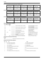
2.10 Zone Doubling
To enable normally closed loops, Section [013], Option [1] must
be ON.
Note: This option should only be selected if Normally Closed
(NC) detection devices or contacts are being used.
Zone Doubling is a feature that will allow you to double the
zones on the main board from 4 to 8. To enable zone doubling,
Section 13 Option [7] must be ON. All zones must be wired
according to the following diagram. Only Normally Closed
devices can be used with zone doubling.
Zone input
COM
Single End Of Line (EOL) Resistors (5600)
Wire A
To enable panel detection of single end of line resistors, Section
[013], Options [1] and [2] must be OFF.
Wire B
RZ1
RZ5
RE1
RE5
TAMPER
TAMPER
N.C.
Zone 1, 2, 3, 4
RE1
1500
N.C.
Zone 5, 6, 7, 8
RZ1
5600
RE5
1500
RZ5
2400
Note: All resistors are 5% tolerance.
Note:
This option should be selected if either Normally Closed (NC)
or Normally Open (NO) detection devices or contacts are being
used.
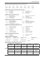
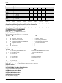
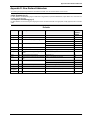
Double End of Line (DEOL) Resistors
Double End of Line resistors allow the panel to determine if the
zone is in alarm, tampered or faulted.
To enable panel detection of double end of line resistors, Section
[013], Option [1] must be OFF and Option [2] must be ON.
Note: If the Double EOL supervision option is enabled, all hardwire zones on the main panel must be wired for Double EOL
resistors, except for Fire, CO and 24-hr Supervisory zones.
Note: Do not use DEOL resistors for Fire zones, CO zones or
24-hr Supervisory zones. Do not wire Fire zones to keypad zone
terminals if the DEOL supervision option is selected.
The loop using the 1500and 5600resistors is the first zone
(Zone 1, 2, 3, or 4). The loop using the 1500and 2400
resistors is the second zone (Zone 5, 6, 7, or 8). For example,
loop 1 is Zone 1 and loop 2 is Zone 5. The following table shows
zone status under certain conditions:
Nominal
Tamper
Zone 1
Zone 5
Fault
–
–
–
11000
–
open
open
–
8600
–
open
restore
–
7100
–
–
–
5400
–
restore
open
–
3900
–
–
–
3000
–
restore
restore
–
1500
–
–
–
Note: The following will be seen by the installer if the end-ofline resistors have not been installed correctly, when both zones
are physically closed:
Zone 1 open, Zone 5 This may be caused by RE1 and RZ1 as
restored
well as RE5 and RZ5 being switched.
Both zones showing This may be caused by RE1 and RZ1, or
as faulted.
RE5 and RZ5, being switched.
Note: This option can only be selected if Normally Closed (NC)
detection devices or contacts are being used.
The following chart shows zone status under certain conditions:
Loop Resistance
Loop Status
0 (shorted wire, loop shorted)
Fault
5600 (contact closed)
Secure
Infinite (broken wire, loop open)
Tamper
11200 (contact open)
Violated
6
Note: If zone doubling is enabled, fire zones should not be programmed. 2-wire smoke loops can still be used.
Note: If zone doubling is enabled, keypad zones should not be
programmed.
Note: If fire zone types are programmed in Section [001], or if a
keypad zone has been assigned, it will not be possible to enable
the zone doubling option in Section [013].
2 Installation
2.11 Fire Zone Wiring
2.13 Keypad Zones
All 4-wire smoke detectors must be wired according to the following diagram:
Each “z” keypad on the system has a zone input to which a
device - such as a door contact - can be connected. This eliminates the need to run wires back to the control panel for every
device.
To install the keypad, open the keypad plastic at the bottom of
the unit. Locate the five terminals on the keypad circuit board.
Connect the four Keybus wires from the control panel: the red
wire to R, the black to B, the yellow to Y and the green to G.
To connect the zone, run one wire to the Z terminal and the other
to B. For powered devices, use red and black to supply power to
the device. Run the red wire to the R (positive) terminal and the
black wire to the B (negative) terminal.
When using end of line supervision, connect the zone according
to one of the configurations outlined in Section 2.9 Zone Wiring.
End of line resistors must be placed on the device end of the
loop, not at the keypad.
All 2-wire smoke detectors must be wired according to the following diagram:
2-wire smoke detector initiating circuit:
•
•
•
•
•
•
•
•
•
Style B (Class B), Supervised, Power Limited
UL Compatibility Identifier . . . . . . . . . . . . . . . . PC14-1
DC Output Voltage . . . . . . . . . . . . . . . . . . 9.3-13.7 VDC
Detector Load . . . . . . . . . . . . . . . . . . . . . . . .2mA (Max.)
Single-end-of-line (SEOL) resistor. . . . . . . . . . . . 2200
Loop resistance . . . . . . . . . . . . . . . . . . . . . . .24(Max.)
Standby impedance . . . . . . . . . . . . . . . . . 1250(Nom.)
Alarm impedance . . . . . . . . . . . . . . . . . . . .650 (Max.)
Alarm current . . . . . . . . . . . . . . . . . . . . . . .94mA (Max.)
2.12 CO Detector Wiring
CO DETECTOR
POWER
- +
ALARM
NC
C
TROUBLE
NO NC
C
NO
-
(SEOL TYPE 41)
RM-1/RM-2
POWER LOOP
SUPERVISORY
RELAY
(12VDC, 35mA)
SEOL
RESISTOR
(5600 ohm)
+
ZONE
INPUT
ANY ANY
COM Z
+-
AUX
PC1404
ALARM
INITIATING
LOOP
RESISTANCE
100 ohm
The following CO detector models can be used with PC1404
v1.0 and higher control panels:
•
Potter Model CO-12/24, UL File E321434
•
Quantum Model 12-24SIR, UL File E186246
•
NAPCO Model FW-CO12 or FW-CO1224, UL File
E306780
•
System Sensor Model CO1224, UL File E307195
Note: Only non 24-hr burglary zones can be configured as keypad zones for UL Listed products.
Assigning Keypad Zones
When using keypad zone inputs, each input used must be
assigned a zone number in Installer Programming.
1. Ensure that you have enrolled all installed keypads into the
desired slots. (See Section 2.6 Keypad Assignment.)
2. Enter [*][8] [Installer Code] to go to Installer Programming.
3. Enter Section [20] for Keypad Programming. There are
eight programming locations in this section, one for each
keypad slot.
4. Enter a 2-digit number (01-08) to specify which zone number should be assigned to the keypad slot. This number
must be entered in the location corresponding to the keypad
to which each zone is connected.
5. Press [#] twice to exit Installer Programming.
Example: The zone on an PK5500 keypad in Slot 8 is to be
assigned Zone 3. In Section [020], scroll to Option [8] and enter
(03).
Note: Keypad Zones 1-4 will replace Zone terminals Z1-Z4 on
the control panel.
Note: Once the keypad zones are assigned, you must also program zone definitions and zone attributes. (See also 5.2 Programming Worksheets).
Note: Keypad zones can only be used for household burglaryinitiated devices. Do not place the device more than 3 feet from
the keypad. The keypad zone must be tested weekly.
PC1404
2.14 PC1404RKZ Installation Instructions
Wiring
1.
2.
1
2
3
4
5
6
7
8
9
*
0
#
The PC1404RKZ is compatible with the PC1404 security system. These instructions shall be used in conjunction with the
Installation Manual of the PC1404 alarm controller.
The PC1404RKZ keypad presents system status using LEDs
along with symbols and numbers. The keypad can be used on
security systems with up to 8 zones.
Specifications
•
•
Supply voltage: 7VDC-14.5VDC
Compatible control panel keybus connection provided by
DSC
•
Connects to control panel via 4-wire keybus
•
One keypad zone input
•
Current draw: 120mA (maximum)
•
Optional tamper version
•
Four programmable function keys
•
Ready (green), Armed (red), and Trouble (amber) status
lights
Note: This keypad is available to order with white (WH) or
yellow (YEL) LED backlights.
Unpacking
The PC1404RKZ package includes the following parts:
•one PC1404RKZ keypad •one tamper switch
• three mounting screws
•one set of Installation Instructions
• three anchors for
•keypad inner door labels
wall-mounting screws
• one end-of-line resistor
3.
Before wiring the unit, ensure that all power (AC transformer and battery) is disconnected from the control panel.
Connect the four Keybus wires from the control panel (red,
black, yellow and green) to the keypad terminals (RED,
BLK, YEL, GRN). Consult the diagram below:
Connect a device, such as a door conPC1404RKZ
tact, to the ‘Z’ terminal of the
PC1404RKZ. This eliminates the
need to run wires back to the control RED BLK YEL GRN Z
panel for the device. To connect the
zone, run one wire from the device to RED BLK YEL GRN To Zone Input
the ‘Z’ terminal and the other wire
from the device to the BLK (black) terminal. For powered
devices, run the red wire to the RED (positive) terminal and
the black wire to the BLK (negative) terminal. When using
end of line supervision, connect the zone according to one
of the configurations outlined in your system’s Installation
Manual.
Applying Power
Once all wiring is complete, apply power to the control panel:
1. Connect the battery leads to the battery.
2. Connect the AC transformer.
For more information on control panel power specifications, see
the control panel Installation Manual.
Note: Do not connect the power until all wiring is complete.
Enrolling the Keypad
See 2.6 Keypad Assignment to enroll the keypad.
Power Save Mode
If power save mode is enabled and AC power fails, all keypad
lights, including backlighting, shut off. The keypad lights will
come back ON after a keypress, entry delay, audible alarm or
keypad buzzer condition (except door chime). The keypad lights
will return to the off state after 30 seconds of no activity. If the
AC fail condition is restored, the keypad lights will be
reactivated.
Keypad Icons
Ready Status
The green ready status icon is on when the system is
ready to arm.
Armed Status
The red armed status icon is on when the system has
been successfully armed.
The trouble status icon is lit when there is a trouble
present on the system. To see if a trouble is present
press [*][2]. If any number is lit, a trouble condition is
present. Refer to your system manual to identify what
trouble condition is present.
The green AC status icon can be configured to indicate
presence or absence of AC; see AC LED Options and
Keypad Toggle Options sections [5] and [6].
The red fire memory icon is lit when a fire alarm is in
progress or has occurred. If zone 4, as an example, is
programmed as a fire zone and goes into alarm, the
keypad will turn on the zone 4 LED and the fire icon to
indicate a fire alarm is present on zone 4.
The alarm memory icon is lit when there is a zone in
alarm memory. To see if there is a zone in alarm
memory press [*][3]. If any number is lit, the
corresponding zone is in alarm memory. Refer to your
system manual for further information.
The bypass icon is lit when a zone is bypassed on the
system. To see if a zone is bypassed press [*][1]. If any
number is lit, the corresponding zone is bypassed. Refer
to your system manual for information on bypassing and
removing a bypass.
The programming icon indicates when the keypad is in
Installer Programming. This LED also activates when
the keypad is busy.
Trouble
Status
Mounting
Mount the keypad where it is accessible to designated points of
entry and exit. Once a dry and secure location is selected, perform the following steps to mount the keypad:
1. Remove the keypad frontplate by inserting a screwdriver
into the slots located on the top of the keypad.
2. Secure the keypad backplate to the wall in the desired location. Use all the screws provided. Use the plastic anchors
supplied if the unit is to be mounted on drywall.
3. To use the keypad tamper, insert the supplied tamper
switch into the opening located in the centre of the backplate, and secure the tamper to the wall with a screw.
4. For tamper use, the backplate should be mounted on a
smooth, flat surface. If mounting on a rough surface, fasten
the enclosed surface tape to the wall to even out the surface
area where the tamper will be positioned.
5. Before attaching the keypad to its backplate, complete the
keypad wiring as described in the next section.
8
AC Status
Fire Memory
Alarm
Memory
Bypass
Programming
Changing the Buzzer Level
The user can change the keypad buzzer frequency by pressing
and holding the [*] key. After the key has been pressed for 2 seconds, the keypad changes the frequency and beeps so the user
2 Installation
can hear the new tone. If the key is held down, every second the
keypad will increment the frequency and sound another tone.
There are 21 levels. Once the desired level is reached, press [*]
to exit.
Programming the Function Keys
The function keys are programed in sections [000][1-4]. By
default, the 4 function keys on the keypad are programmed as
Stay Arm (03), Away Arm (04), Chime (06), and Sensor Reset
(14). Activate the function keys as follows:
Function key 1 - Press and hold the #2 key for 2 seconds
Function key 2 - Press and hold the #5 key for 2 seconds
Function key 3 - Press and hold the #8 key for 2 seconds
Function key 4 - Press and hold the #0 key for 2 seconds
See Keypad Function Keys below for the other function key
options available for your system.
3.
To adjust the intensity of the backlighting LEDs, repeatedly
press [9].
When complete, press [#] to exit.
4.
Programming worksheet
[000] Keypad Programming
1.Enter [*][8][Installer Code].
2.Enter [000] to go to keypad programming.
[0] Keypad Enrollment
Valid entries are 01-18; e.g., enter [11] for partition 1, slot 1.
1st digit: Enter 0 to 8 for partition assignment (0 = Global Keypad).
2nd digit: Enter 1 to 8 for slot assignment
Default: 11
I_________I________|
[1]-[4] Function Key Assignments
Defaults
Emergency Key Options (Fire, Auxiliary, Panic)
You can enable or disable the Fire, Auxiliary and Panic keys at
each keypad. These keys are enabled by default. To turn any of
the emergency keys on or off on the keypad:
1. Enter [*][8][Installer Code].
2. Enter [000] to go to keypad programming.
3. Enter section [6].
4. To turn the emergency key options on or off, press [1], [2],
or [3]:
[1] ON=Fire key enabled
OFF=Fire key disabled
[2] ON=Auxiliary key enabled OFF=Auxiliary key disabled
[3] ON=Panic key enabled
OFF=Panic key disabled
5. When complete, press [#] to exit.
Activating Emergency Keys
• Fire Key
To activate a fire alarm, press and hold keys #1 and #3 simultaneously for 2 seconds.
• Auxiliary Key
To activate an auxiliary alarm, press and hold keys #4 and #6
simultaneously for 2 seconds.
• Police Key
To activate a police alarm, press and hold keys #7 & #9 simultaneously for 2 seconds.
Night Light Feature (available in PC1404RKZWH order
code)
White LEDs are on the left and right side of the keypad to make
the keypad easier to locate in the dark. To turn the night lights on
or off:
1. Enter [*][8][Installer Code].
2. Enter [000] to go to keypad programming.
3. Enter Keypad Toggle Options section [6].
4. Turn option 4 on or off to enable or disable the night light
feature.
5. When complete, press [#] to exit.
AC LED Options
The AC LED can be enabled or disabled, and can be configured
to indicate if AC is present or absent. To turn the AC LED on or
off:
1. Enter [*][8][Installer Code].
2. Enter [000] to go to keypad programming.
3. Enter Keypad Toggle Options section [6].
4. To turn the AC LED feature on or off, press 5.
5. To control whether the LED indicates AC present or absent,
press 6.
6. When complete, press [#] to exit.
Backlighting Intensity Adjustment
The keypad has 5 backlighting intensity settings. To adjust the
backlighting intensity:
1. Enter [*][8][Installer Code].
2. Enter [000] to go to keypad programming.
[1] Key 1
03
Stay
[2] Key 2
04
Away
[3] Key 3
06
Chime
[4] Key 4
14
Sensor
Reset
I_________I________| I_________I________| I_________I________| I_________I________|
Keypad Function Keys
[00] - Null key (key not used)
[13] - Command output 1 (*71)
[14] - Command output 2 (*72)/
Sensor reset
[03] - Stay arm
[15] - Not used
[04] - Away arm
[16] - [*][0] Quick exit
[05] - [*][9] No entry arm
[17] - [*][1] Activate stay/away
[06] - [*][4] Chime On/Off
[18] - Not used
[07] - Not used
[19] - Command output 3 (*73)
[08] - [*]1]Bypass mode
[20] - Night arming
[09] - [*]2] Trouble display
[21] - Command output 4 (*74)
[10] - Not used
[22]-[24] Not used
[11] - [*][5] User code programming [25] - Instant stay arm
[12] - [*][6] User functions
[26]-[32]- Not used
[01]-[02] - Not used
[6] Keypad Toggle Options
Option
1
2
3
4
[F] key enabled/disabled
[A] key enabled/disabled
[P] key enabled/disabled
Night light enabled/disabled: When enabled, the
white LEDs on each side of the keypad are activated. When disabled, the white LEDS on each
side of the keypad are deactivated.
5 AC LED enabled/disabled: When enabled, the
keypad’s AC LED indicates either the presence or
absence of AC power to the control panel,
depending on the programming of option 6 in section [000][6]. When disabled, the keypad’s AC
LED remains off in all conditions.
6 AC LED on when AC present/AC LED on when
AC absent: This toggle option requires option 5 in
section [000][6], AC LED enabled/disabled, to be
enabled. When this option is on, the keypad’s AC
LED turns on to indicate that the control panel has
AC power, and turns off to indicate that AC power
has been lost. When this option is off, the keypad’s AC LED turns on to indicate that AC power
has been lost, and turns off to indicate that the
control panel has AC power.
7-8 Not used
PC1404
3 Keypad Commands
Use any compatible keypad to enter commands and/or program the PC1404 security system. The LED keypad uses function and zone
indicator lights to represent alarm functions and status. The LCD keypad provides a written description on the liquid crystal display and
uses function indicator lights to communicate alarm status to the user.
The PC1404 User Manual provides basic directions for arming and disarming the system, bypassing zones and performing user functions from the keypads. The following sections provide additional details on these functions.
3.1 Arming and Disarming
For a description of basic arming and disarming, please see the PC1404 User Manual. For other methods of arming, please refer to
[*][0] – Quick Arm and [*][9][User Code] – No-Entry Arming.
The event buffer will log “armed in stay mode,” “armed in away mode,” or “armed in night mode” whenever the system is armed.
The arming procedure initiated by pressing Away function key on keypad is the same as the arming procedure initiated by entering user
codes. For CP-01 systems, if there is no exit event (delay 1 zone violated and restored) prior to the exit delay expiring, the system will
be armed in Stay mode.
In an attempt to prevent false alarms, the Audible Exit Fault will notify the user of an improper exit when they arm their system. If a
non force-arming Delay 1 or Delay 2 type zone is left open at the end of the exit delay, the entry delay will begin immediately and the
bell or siren will sound a steady alarm for the entry delay period. At the end of the entry delay period, if the system has not been disarmed it will go into alarm. This feature can be turned OFF in Section [013], Option [6].
3.2 Auto Bypass – Stay Arming
Stay arming allows the user to arm the system without leaving the premises. All zones programmed as stay/away will be bypassed when
the user stay arms the system, so that the user does not have to bypass interior zones manually. (See “Zone Programming” in PC1404
Programming Descriptions. For these descriptions, see the Technical Library section of http://www.dsc.com.)
When the system is armed using a valid access code, if any zones on the system have been programmed as stay/away zones, the Bypass
light will turn ON. The panel will then monitor all zones programmed as Delay 1 and Delay 2 zones, such as designated entry/exit
doors. If a delay zone is not violated by the end of the exit delay, the panel will bypass all stay/away zones. The Bypass light will remain
on to inform the user that the interior zones have been automatically bypassed by the panel. If a delay zone is violated during the exit
delay, the system will arm in Away mode and all stay/away zones will be active after the exit delay expires.
The user can arm the stay/away zones at any time by entering the [*][1] keypad command. (See “[*][1] Bypassing and Activating Stay/
Away and Night Zones”.)
Stay arming can also be initiated by pressing and holding the Stay function key for two seconds on the supported keypads, if programmed by the installer. For more information regarding Stay arming, see [000] in Keypad Function Programming in PC1404 Programming Descriptions.
3.3 Automatic Arming
The system can be programmed to arm at the same time each day. Upon entry of this section, enter 4 digits for the 24 Hour Auto-Arm
time. At the selected Auto-Arm time, the keypad buzzers will sound for the time programmed in Section [199] to warn that an AutoArm is in progress. The bell can also be programmed to squawk once every 10 seconds during this warning period. When the warning
period is complete, the system will arm with no exit delay and in the Away Mode. Note: For CP-01 systems, the system will arm with
an exit delay. If no Delay 1 zone violation and restore occurs during this exit delay, the system will arm in Away mode. If a Delay 1
zone is left violated when the exit delay ends, an audible exit fault will occur if the feature is enabled. The exit delay restart feature
applies to this entry delay (see Section [18] Option 7.)
Auto-Arming can be cancelled or postponed only by entering a valid access code during the programmed warning period. When the
code has been entered, the warning will be silenced and Auto-Arming will be cancelled or postponed, depending on the programming
of Section [175]. Auto-Arming will be attempted at the same time the next day. Whenever the Auto-Arming process is canceled or postponed, the Auto-Arm Cancellation Reporting Code will be transmitted (if programmed).
If arming is inhibited by one of the following, the Auto-Arm Cancellation transmission will be communicated.
- AC / DC Inhibit Arm
- Latching System Tampers
- Zone Expander Supervisory Fault
Note: PC1404 only supports one entry of Auto-Arm Time programming, so the programmed time shall be used for every day.
3.4 Night Arming
Night arming is intended to arm the perimeter and restrict movement to designated areas in the interior (e.g., hallways from bedrooms
to bathrooms).
If night zones are programmed, entering [*][1] while the system is armed in stay mode will activate all interior zones except those programmed as night zones. The panel can also be armed in Night mode by pressing the Night Arm function key for 2 seconds while the
system is disarmed. The Ready light must be on (disarmed) or the system must be armed in Stay mode to Night arm the system. In
Night mode only night zones (Zone definition 37) are bypassed. When activated, no acknowledgement beeps are sounded, the exit
delay is silent and the panel logs “Armed in Night Mode.” If no night zone types are programmed, the system arms in Away mode and
the panel logs “Armed in Away Mode.”
3.5 [*] Commands
The [*] key commands provide an easy way for the user to access basic system programming – such as programming access codes or
bypassing zones. The user can also use the [*] key commands to check on the system’s status, including viewing trouble conditions and
displaying the event buffer on the LCD keypad.
The [*] key commands can be performed from both LCD and LED keypads. The LED keypad uses the zone indicator lights to display
command information. The LCD display provides written information, guiding the user through each command. The commands in this
section are explained as viewed from an LED keypad. When using an LCD keypad, use the arrow keys (< >) to scroll through information provided. Otherwise, the functions remain the same for both keypad types.
10
3 Keypad Commands
[*] Commands
The following is a list of the [] commands available and a description of each:
[][1]
Bypass (disarmed state)/Reactivate Stay/Away and Night Zones (armed state)
[][2]
Display Trouble Conditions
[][3]
Display Alarm Memory
[][4]
Door Chime Enable/Disable
[][5][Master/Supervisory Code]
User Code Programming
[][6][Master/Supervisory Code]
User Functions
[][7][x]
Command Functions 1–4
[][8][Installer Code]
Installer Programming
[][9][User Code]
No-Entry Arming
[][0]
Quick Arm (disarmed state)/Quick Exit (armed state)
[*][1] Bypassing and Activating Stay/Away and Night Zones
LED Keypad
Press [][1] to enter the bypass mode. If the Code Required for the Bypass option is enabled, enter a valid user code. The Bypass light
will flash. The keypad will turn ON the corresponding zone light to indicate a zone is bypassed. To bypass or unbypass a zone, enter the
2-digit zone number. Once the correct zones are bypassed, press [#] to exit. The Bypass light will be ON if any zones are manually
bypassed.
LCD Keypad
Press [][1] to enter the bypass mode. If the Code Required for the Bypass option is enabled, enter a valid user code. The keypad will
display ‘Scroll to View Zones’. The keypad will display the programmed zone labels for the zones and include the letter ‘O’ in the bottom right corner if the zone is violated, or the letter ‘B’ if the zone is bypassed. Scroll to the appropriate zone and press the [] key to
change the bypass status (or enter the 2-digit zone number). Once the correct zones are bypassed, press [#] to exit.
Additional Bypass Commands:
Bypass Recall:
Press [99]. The keypad will recall the last group of zones that were bypassed.
Clear Bypass:
Press [00]. The keypad will clear the bypass on all zones.
Save Bypass:
Press [95]. The keypad will save which zones are manually bypassed.
Recall Save:
Press [91]. The keypad will recall the bypassed zones that were saved.
i
Hold-up Zones cannot be assigned to bypass groups.
[*][1] Activate Auto-Bypassed Stay/Away and Night Zones
When the system is armed in the Stay mode by (a) arming and not exiting through a delay zone during the exit delay; or (b) pressing a
function key programmed for Stay Arm or Arming Without Entry Delay [][9], the zones programmed as “Stay/Away” or “Night” type
zones are automatically bypassed. This [] [1] command is used to remove the automatic bypass from the Stay/Away zones to fully arm
the system zones to fully or “Night” arm the system. Once this command is executed, all Stay/Away type zones will become active after
the programmed Exit Delay time, making the system armed in Night or Away mode. When the system is armed in the Away or Night
mode, if enabled by the installer, this [][1] command will bypass all of the “Stay/Away” type zones immediately, making the system
armed in Stay mode. Night or Away mode is determined by whether there is a Night zone programmed on the system.
Note: Although there is an exit delay timer running, it is only an arming delay for the Stay/Away zones, and not a true exit delay where
all non-24 hour zone types can be opened and closed for the purpose of exiting. Any zone type that is not a Stay/Away zone type will
start its alarm sequence if violated during this “exit delay”. Users should press 0 next to start a Quick Exit Delay to exit the premises.
[*][2]Trouble Display
The panel continuously monitors a number of possible trouble conditions. If one of these conditions occurs, the keypad “Trouble” indicator will light and the audible indication will sound, two short beeps every 10 seconds (except AC failure). When the [#] key is pressed
the audible indication will stop but the trouble is not cleared. Trouble conditions are logged to the Event Buffer and most troubles can
also be transmitted to the monitoring station.
To view troubles, press [] then [2]. The “Zone” lights or LCD text display the trouble conditions 1-8.
Troubles 1, 5, and 6 can be expanded for more details by pressing the corresponding [1], [5], or [6] key.
Press [#] to return to the “Ready” mode. There is no Trouble memory. The Event Buffer can be used to achieve this function.
11
PC1404
Viewing of troubles is now permitted while armed. The various troubles are described below:
Light
Trouble
1
Service Required: Press [1] to determine the specific trouble. Lights 1–8 will light up to indicate the trouble.
Light [1] Low Battery: The standby battery's voltage is measured under load every 3 minutes and during a System Test.
The limits of alarms and restores are determined by the Swinger Shutdown (Maintenance Troubles & Restores) counter.
Set at 3 by default, there will be 3 Low Battery Troubles and 3 Low Battery Restores before latching. The latching is reset
at midnight or upon arming.
Light [2] Bell Circuit Trouble: If the bell circuit is overdrawn or the bell circuit is open, a keypad trouble is generated and a
Bell Circuit Trouble can be reported.
Light [3] General System Trouble: Any peripheral module trouble will be indicated and communicated with a General
Trouble, but logged to the event buffer with a detailed description.
Light [4] General System Tamper: Any peripheral module tamper will be indicated and communicated with a General
Tamper but logged to the event buffer with a detailed description.
Light [5] General System Supervisory: If the system loses Supervisory signals from a peripheral module, this will be indicated and communicated with a General Supervisory but logged to the event buffer with a detailed description.
Light [6] Not used.
Light [7] PC5204 Low Battery: The PC5204 Module has detected a Low Battery Condition.
Light [8] PC5204 AC Fail: The PC5204 Module has detected an AC Power Failure. This Trouble will initiate the keypad
trouble beeps after the AC fail transmission delay if Trouble #2 is NOT present.
2
3
4
5
6
AC Failure: There is no audible annunciation on AC power failure unless trouble beeps on AC failure are enabled in
Section [018] Option [8]. The system “Trouble” light will come ON but the audible indication will not sound until there is a
low battery condition. Transmission delay can be programmed for 000 to 255 minutes/hours. If the AC Fails, the battery
will be continuously checked until the panel shuts down.
Telephone Line Monitoring Trouble (TLM): The telephone line voltage is measured every 3 seconds. If the voltage drops below 1 to 3 volts for the number of consecutive checks programmed in Section [377], a Telephone Line Trouble is generated. This additional check denomination may fluctuate from board to board, as it is dependant on hardware
component tolerances. The TLM Restore shall occur when the value in Section [377] is reached.
Failure to Communicate (FTC): If the digital communicator is unsuccessful in communicating with any of the programmed telephone numbers, a failure to communicate trouble will be generated. If a later attempt to communicate is
successful, the panel can also transmit the FTC restore reporting code and all previous unsuccessful events. If the digital
communicator is unsuccessful in communicating with any of the programmed telephone numbers, a failure to communicate trouble will be generated. If a later attempt to communicate is successful, the panel can also transmit the FTC
restore reporting code and all previous unsuccessful events.
Zone Fault (including Fire Zone): If any zone on the system is in the Trouble state, this trouble will be generated.
For hardwired zones (excluding Fire) using double end of line supervision, this is the shorted state. If DEOL is not used,
Zone Troubles can still be generated on Fire Zones (open state). If [5] is pressed in the Trouble mode, the keypad will
now display all of the zones in trouble. Fire Zone Faults are identified in the Event Buffer. They log a “Fault Zone X” followed by a generic “Fire Trouble”. This has been done so that intermittent wiring problems may be tracked down via the
Event Buffer.
This trouble will be generated and displayed in the armed state if a Fire trouble is present. It will also restart the Trouble
beeps. If any zone enters this Trouble state (short), the keypad buzzers will sound trouble beeps to annunciate the condition.
Zone Tamper: This trouble is used with DEOL Zone Supervision only. If any zone is in the Tamper state, this trouble will
be generated. Zones excluded from this are Fire and zones not supporting the DEOL configuration (LINKS answer, Keyswitch). Press [6] in the Trouble mode to display all of the tampered zones. If any zone enters this Tamper state (open), the
keypad buzzers will sound trouble beeps to annunciate the condition.
7
Not Used
8
Loss of System Time: When the panel is powered up, the internal clock needs to be set to the correct time. This trouble is cleared when an attempt is made to reset the clock.
[*][3] Alarm Memory
When Disarmed, press [*] then [3] to enter the alarm memory mode. The “Memory” light will flash and any alarm caused during the
last armed period will be displayed on the zone lights.
Press [#] to return to the “Ready” mode. If [#] is not pressed, the keypad will time out in 30 seconds.
There is no memory of previous armed states. The Event Buffer can be used to achieve this function.
[*][4] Door Chime On/Off Command
When Armed/Disarmed, to turn the feature on or off, enter [*][4].The Door Chime feature is used to sound a tone from the keypad
whenever a zone programmed as a Chime type is activated. When the Door Chime feature is turned ON, the keypad will beep several
times whenever a Chime zone is activated. When the feature is being turned ON, the keypad will beep 3 times and the LCD will display
“Door Chime Feature ON”. When the feature is being turned OFF, the keypad will sound a single long tone and the LCD keypad will
display “Door Chime Feature OFF”.
[*][5] Program User Codes
The following table identifies available user codes:
Code
[01] – [39]
[40]
Type
General User Codes
Master Code
Function
Determined by attributes programmed below
When Disarmed, enter [*][5] to access the attribute programming mode.
1) The default attributes of a new code will be the attributes of the code used to enter [*][5] whether it is a new code or an existing code
being programmed.
2) All user codes will now have a check so that they cannot be + or -1 of any other code.
12
3 Keypad Commands
Inherent Attributes (All codes except Installer and Maintenance)
Arm/Disarm - Any access code is valid for arming and disarming.
Command Outputs [*][7][1] - If the output requires an access code entry, any valid access code can be used.
Programmable Attributes ([*][5][Master/Supervisor Code][99][Code])
[1] Supervisor’s Code – This code is used for validation when entering the [*][5] User Code Programming section. However, this code
can only program codes which have equal or lesser attributes. These attributes are changeable.
[2] Duress Code – Duress codes are standard user codes that will transmit the Duress Reporting Code whenever the code is entered to
perform any function on the system.
Duress codes are not valid when entering [*][5], [*][6] or [*][8] sections.
A code cannot be programmed as a duplicate or as a code + or -1.
[3] Zone Bypassing Enabled – This attribute controls whether the user can bypass zones. This also requires that option Code Required
for Bypassing option is turned ON.
[4] Remote Access – This attribute controls access to the system via a telephone during remote access.
[5] For Future Use
[6] For Future Use
[7] Bell Squawk upon Arming/Disarming – This attribute is used to determine whether an access code should generate an arming/disarming bell squawk at the end of exit delay. The attribute is off at default for all access codes, and this feature is meant to be used when
Bell Squawk on Arming/Disarming is disabled in Section [014]. However, if the away function key is pressed on the system keypad,
followed by an access code with this attribute enabled, the bell will still squawk.
[8] One-Time-Use Code – When the one-time-use code is entered on the system, the user of the code will be able to arm the panel with
the code as many times as they want. They will also be able to disarm the system using the code once per day. The disarming operation
will be reset at midnight, or if the code or its attributes are viewed in the [*][5] Access Code Programming. A code programmed as onetime use can be used to access other star menus that require an access code.
Notes on Access Codes and Programming
Note: [*][5][MASTER CODE] [01 to 39 40] to program access codes.
[*][5][MASTER CODE][99] enters the Attribute Mode [01 to 39] to edit access code attributes.
Note: The Master Code's attributes cannot be changed.
Note: When a new code is programmed in either [*][5] or through Installer Programming, it will be checked against all other codes in
the system. If a duplicate code is found, an error tone is given, and the code is returned to what it was before it was changed. This
applies to both 4- and 6-digit codes.
Note: In [*][5] if a duress code is being programmed, it will be checked to make sure that it is not 1 digit more than any other code in
the system. This will only apply to the least significant digit and does not roll over to the next digit. If a user code is 1234, then the
duress codes 1234 and 1235 are not allowed. If the user code is 1239, then duress cannot be 1239 or 1230, but could be 1240. This
applies to both 4- and 6-digit codes.
Note: See also [006] Installer Code and [008] Maintenance Code.
Erasing an Access Code
To erase an access code, the user will have to go into the base menu and then select the user number and enter [*] as the first digit. If [*]
is entered, the system will delete the code immediately and the user will be returned to select another code.
13
PC1404
[*][6] – User Functions
To access the User Functions section, when disarmed, press [][6] followed by the master or supervisor code. Select one of the functions described below by pressing the corresponding number or scrolling to the desired option then pressing [].
[1]
Program Time and Date: Enter the time and date using the following format [HH:MM] [MM/DD/YY]. Program the time
using military standard (e.g., 8:00 pm = 20:00 hours). Valid entries for the Hour are 00-23. Valid entries for the Minute are
00-59.
[2]
Auto-Arm Control: Pressing [2] while in the User Function menu will enable (3 beeps) or disable (one long beep) the AutoArm feature. With this feature enabled, the panel will automatically arm in the Away mode (Stay Away zones active) at the
same time each day. The Auto-Arm time is programmed with the [*][6][Master Code][3] command.
Note: Keypads are required if Auto-Arm is to be used.
[[3]]
Auto-Arm Time: The system can be programmed to arm at the same time each day. Upon entry of this section, enter 4 digits
for the 24 Hour Auto-Arm time. At the selected Auto-Arm time, the Keypad Buzzers will sound for the programmed time in
Section [199] to warn that an Auto-Arm is in progress. The bell can also be programmed to squawk once every 10 seconds
during this warning period. When the warning period is complete, the system will arm with no exit delay and in the Away
Mode. Auto-Arming can be cancelled or postponed only by entering a valid access code during the programmed warning
period. When the code has been entered, the warning will be silenced and Auto-Arming will be canceled or postponed,
depending on the Programming of Section [175]. Auto-Arming will be attempted at the same time the next day. Whenever
the Auto-Arming process is cancelled or postponed, the Auto-Arm Cancellation Reporting Code will be transmitted (if programmed).
The Auto-Arm Cancellation will be transmitted if arming is inhibited by one of the following:
• AC/DC Inhibit Arm
• Latching System Tampers
• Zone Expander Supervisory Fault.
PC1404 only supports one entry of Auto-Arm Time programming, which means the programmed time shall be used for
every day auto arm.
[4]
System Test: The system's Bell Output (2 sec), Keypad Lights and Communicator are tested. This test will also measure the
panel's standby battery. The system activates the siren output on medium volume for 2 seconds followed by full volume
alarm for 2 seconds. All display lights and LCD pixels turn on. When the System Test event is successfully received at the
monitoring station, the keypad will sound ringback, a series of 8 beeps.
[5]
System Serv/DLS: If enabled, this opens a window where incoming rings on the phone line are detected by the panel. This
window remains open for 6 hours. After the window has expired, DLS access will not be permitted.
[6]
User Call-up: If enabled by the installer, when this command is executed, the panel will make 1 attempt to call the downloading computer. The downloading computer must be waiting for the panel to call before downloading can be performed.
[7]-[0]
For Future Use
Additional Keypad Functions
The following additional keypad functions are available:
Event Buffer:
Brightness Control:
Contrast Control:
Buzzer Control:
View the 128-event panel buffer
Adjust the display backlighting level for optimal viewing
Adjust the display contrast level for optimal viewing
Adjust the keypad buzzer tone for optimal sound
[*][7] – Command Outputs
When armed or disarmed, press [*][7] followed by the command output number 1 to 4. When any command output is activated, three
acknowledgement beeps are heard. The system can be configured to require a valid access code to activate a command output.
[*][8] – Installer Programming
When disarmed, press [][8][Installer Code] to enter Installer Programming. Installer Programming allows the installer to program all
system functions. Refer to Section 4.1 Installer Programming for details. The PC1404 v1.1 is completely programmable from any system keypad using this command.
Note: Three-digit entries are required for section entry. When an error is made in attempting to enter a section number, [#] can be
pressed. If [#] is the first digit pressed, however, the keypad will return to the base menu.
Note: Once inside Installer Programming, the keypad will remain there for 20 minutes after the last keypress.
Note: All system events that occur while in Installer Programming will be logged to the Event Buffer and printed on the system printer;
however, these events will not be transmitted.
Note: When viewing data in sections with an LCD keypad, use the [<] and [>] keys to scroll. If using an LED keypad, press the [F] key
to scroll.
[*][9][User Code] – No-Entry Arming
When disarmed, entering [*][9] or pressing a function key programmed for No Entry Arm before entering an access code arms the
panel without any entry delay on the perimeter delay zones and bypasses zones that are defined as "Stay Away". This command is used
to arm the system while at home. When the system is armed in this mode, the "Armed" light will be ON flashing and the bypass light
will be on to indicate the "Stay Away" zones are bypassed. Once the panel is armed in this mode, using [*][1] will remove the bypass
from the "Stay Away" zones if they were NOT manually bypassed. The [*][1] command used here only removes the bypass from zones
14
3 Keypad Commands
that have been automatically bypassed with the [*][9] command. Delay Stay/Away and Interior Delay Zones will still have Entry Delay
on a [*][9] armed panel.
[*][0] – Quick Arm
When disarmed, press [*][0] to activate Quick Arm. Quick Arm may be used as a convenience for regular users or when the system is
to be armed by individuals who are not authorized to disarm the system. This panel will log either "Armed in Stay Mode" or "Armed in
Away Mode" for this closing type.
[*][0] – Quick Exit
When armed, press [*][0] to activate Quick Exit. Quick Exit allows the user 2 minutes to exit the premises through any delay zone without altering the status of the system if the Quick Exit feature is enabled. After [*][0] is entered, one and only one delay zone may be
tripped. If the delay zone is left unrestored at the end of the 2 minutes, it will begin its entry delay sequence. Any additional activity on
any other active zone will cause that zone to begin its alarm or delay sequence. Quick Exit is not designed to extend the standard Exit
Delay.
15
PC1404
4 Programming
The PC1404 can be programmed using the following methods:
Programming Method
Description
Procedure
Installer Programming
Allows direct access to all programming sections. Press [][8][Installer’s Code] while the system is disarmed.
See 4.1 Installer Programming for details.
DLS Programming
Allows programming to be downloaded using
DLS-V™ software.
DLS programming can be performed locally with
a PC-Link cable and a PC with DLS-V software
installed.
DLS programming can be performed remotely via
telephone line.
DLS Programming can be set up from Installer
Programming (see [401] Downloading Option Codes).
Note: Panel communications will interfere with the
PC-link connection. Ensure the PC1404 is not
communicating before attempting a local DLS
connection.
4.1 Installer Programming
The following section of the manual describes the Installer Programming functions and how to program the various sections.
Read the following section of the manual very carefully before you begin programming. We also recommend filling out the Programming Worksheets section before you program the panel.
Installer Programming is used to program all communicator and panel options. The Installer Code is [5555] by default (555555 if 6
digit codes are used) but should be changed to prevent unauthorized access to programming.
From an LED or fixed message LCD keypad:
1. Enter [][8][Installer Code].
The Program light (or System light on the PC1555RKZ) will flash to indicate that you are in programming mode.
The Armed light will turn on to indicate that the panel is waiting for the three-digit programming section number.
2. Enter the three-digit section number corresponding to the section you wish to program.
The Armed light will turn off.
The Ready light will turn on to indicate that the panel is waiting for the information required to complete programming the
selected section.
3. Enter the information required to complete section programming (i.e., numbers, HEX data, or ON/OFF options).
Note: If the three-digit section number entered is invalid, or if the module which pertains to the section is not present, the keypad will
sound a two second error tone.
From an LCD keypad:
1. From any keypad, enter [][8][Installer Code]. The Keypad will display ‘Enter Section’ followed by three dashes.
2. Enter the three-digit number corresponding to the programming section number you wish to program. The keypad will now display the information required to complete programming the selected section.
3. Enter the information required to complete section programming (i.e., numbers, HEX data, or ON/OFF options).
If you enter information into a section and make a mistake, press the [#] key to exit the section. Select that section again and re-enter the
information correctly.
Note: There must be one digit in each box in the programming section in order for the change to be valid.
4.2 Programming Decimal Data
A set number of programming boxes are allotted for each section requiring decimal data (e.g.: codes, telephone numbers). If a digit is
entered for each program box, the panel will automatically exit from the selected programming section. The Ready light will turn OFF
and the Armed light will turn ON.
On the PC1555RKZ and PK5508 keypads, you can also press the [#] key to exit a programming section without entering data for every
box. This is handy if you only need to change digits in the first few programming boxes. All other digits in the programming section
will remain unchanged.
4.3 Programming HEX Data
On occasion, hexadecimal (HEX) digits may be required. To program a HEX digit, press the [] key. The panel will enter HEX programming and the Ready light will begin to flash.
The following are the numbers that should be pressed to enter the appropriate HEX digit:
1=A
2=B
3=C
4=D
5=E
6=F
Once the correct HEX digit has been entered, the Ready light will continue to flash. If another HEX digit is required, press the corresponding number. If a decimal digit is required, press the [] key again. The Ready light will turn on and the panel will return to regular
decimal programming.
Example:
To enter ‘C1’ for a closing by user 1, you would enter:
[][3][], [1]:
[] to enter Hexadecimal mode (Ready light flashes)
[3] to enter C
[] to return to decimal mode (Ready light is solid)
[1] to enter digit 1
Note: If Ready light is flashing, any number you enter will be programmed as the HEX equivalent.
16
4 Programming
If you are using a pulse communications format, a decimal zero [0] does not transmit. Programming a zero [0] tells the panel not to send
any pulses for that digit. Decimal zero [0] is a filler digit. To transmit a zero [0], it must be programmed as a Hexadecimal ‘A’.
Example:
For the three digit account number ‘403’, you would enter:
[4], [,[1][,][3], [0]:
[4] to enter the digit 4
[,] to enter Hexadecimal mode (Ready light flashes)
[1] to enter A
[,] to return to decimal mode (Ready light is solid)
[3] to enter the digit 3
[0] to enter the digit 0 as a filler digit.
4.4 Programming Toggle Option Selections
Some programming sections contain several toggle options. The panel will use zone lights 1 through 8 to indicate if the different
options are enabled or disabled. Press the number corresponding to the option to turn it ON or OFF. Once all the toggle options have
been selected correctly, press the [#] key to exit the section and save the changes. The Ready light will turn OFF and the Armed light
will turn ON.
Refer to the Programming Worksheets in this manual to determine what each option represents and whether the light should be ON or
OFF for your application.
4.5 Viewing Programming
LED and Fixed Message LCD Keypads
Any programming section can be viewed from an LED keypad. When a programming section is entered, the keypad will immediately
display the first digit of information programmed in that section. The keypad displays the information using a binary format, according
to the following chart.
Press the Fire keys to advance to the next digit. When all the digits in a section have been viewed, the panel will exit the section; the
Ready Light will turn OFF and the Armed light will turn ON, waiting for the next three-digit programming section number to be
entered. Press the [#] key to exit the section.
LCD Keypad
When a programming section is entered, the keypad will immediately display all the information programmed in that section. Use the
arrow keys (< >) to scroll through the data being displayed. Scroll past the end of the data displayed or press the [#] key to exit the section.
4.6 DLS Programming
4.6.1 Local Programming with PC-Link
Follow the steps in the sequence indicated below to set up local programming using DLS:
1. Initiate a DLS PC-Link session on the DLS computer.
2. Connect the PC-Link cable between the computer and the header pins on the alarm system.
3. When the session is complete, remove the PC-Link cable from the alarm system.
4. Complete installation.
Note: Connecting the DLS PC to the system automatically initiates the connection.
17
PC1404
5 Programming Worksheets
Note: For more details, see PC1404 Programming Descriptions in the Technical Library section of http://www.dsc.com.
5.1 Index to Programming Worksheets
Programming Option
PWS
[000] Keypad Function Key Programming ..................... 19
[001] Zone Definitions .................................................... 19
[005] System Times ....................................................... 20
[006] Installer Code........................................................ 20
[007] Master Code ......................................................... 20
[008] Maintenance Code................................................ 20
[009] PGM Output Prog. ............................................... 20
[010] PC5208 PGM Output Prog ................................... 20
[011] PC5204 PGM Output Programming...................... 21
[012] Keypad Lockout Options....................................... 21
[013] First System Options............................................. 21
[014] Second System Options ....................................... 21
[015] Third System Options ........................................... 21
[016] Fourth System Options ......................................... 21
[017] Fifth System Options............................................. 22
[018] Sixth System Options............................................ 22
[020] Keypad Zone Assignments ................................... 22
[022] Ninth System Options ........................................... 22
[023] Tenth System Options........................................... 22
[030] Zone Loop Response Options .............................. 23
[101]-[108] Zone Attributes............................................. 23
[168] Daylight Savings Time Begins .............................. 24
[169] Daylight Savings Time Ends ................................. 24
[170] PGM Output Timer ................................................ 24
[175] Auto-Arm Postpone Timer..................................... 24
[176] Cross Zone/Police Code Timer ............................. 25
[181] Auto-Arm Time of Day........................................... 25
[190] No Activity Arming Pre-Alert Timer........................ 25
[191] No Activity Arming Timer ....................................... 25
[199] Auto-Arming Pre-Alert ........................................... 25
[301] First Telephone Number........................................ 25
[302] Second Telephone Number .................................. 25
[303] Third Telephone Number ...................................... 25
[304] Call Waiting Cancel String .................................... 25
[305] Fourth Telephone Number .................................... 25
[310] System Account Code........................................... 25
[320] Alarm Rep. Codes................................................. 25
[324] Alarm/Restore Rep. Codes ................................... 25
[328] Misc. Alarm Rep. Codes ....................................... 25
[329] Priority Alarm/Restore Rep. Codes ....................... 26
[330] Tamper Rep. Codes .............................................. 26
[334] Tamper Restore Rep. Codes ................................ 26
[338] Misc. Tamper Rep Codes...................................... 26
[339]-[340] Closing (Arming) Rep. Codes ...................... 26
[341] Misc. Closing (Arming) Rep. Codes...................... 26
[342]-[343] Opening (Disarming) Rep. Codes ............... 26
[344] Misc. Opening (Disarming) Rep. Codes. .............. 27
[345] Maintenance Alarm Rep. Codes ........................... 27
[346] Maintenance Restore Rep. Codes........................ 27
[347] Misc. Maintenance Rep. Codes ............................ 27
[348] Test Transmission Rep. Codes ............................. 27
[350] Communicator Format Options............................. 27
[351] Alarm/Rest. Comm. Call Directions....................... 27
[359] Tamper Alarm/Rest. Comm. Call Directions.......... 27
18
Programming Option
PWS
[367] Opening/Closing Comm. Call Directions............... 28
[375] System Maint. Alarm/Rest. Comm Call Dir. .......... 28
[376] System Test Trans. Comm. Call Directions........... 28
[377] Communication Variables ..................................... 28
[378] Test Transmission Time of Day ............................. 28
[380] First Communicator Options ................................. 28
[381] Second Communicator Options ............................ 29
[382] Third Communicator Options ................................ 29
[383] Fourth Communicator Options.............................. 29
[401] Downloading Option Codes .................................. 29
[402] Downloading Computer’s Tel. Number ................. 30
[403] Downloading Access Code ................................... 30
[404] Panel ID Code....................................................... 30
[405] Answering Machine Double Call Timer ................. 30
[406] Number of Rings to Answer On ............................ 30
PGM Output Attributes ................................................ 30
[501]-[502] Main Board .................................................. 30
[503]-[510] PC5208........................................................ 30
[511]-[514] PC5204 ........................................................ 30
[551]-[564] PGM Zone Assignment................................ 31
[601] Closing (Arming) Reporting Codes ....................... 32
[605] Opening (Disarming) Reporting Codes................. 32
[700] Automatic Clock Adjust ......................................... 32
[701] First International Options..................................... 32
[702] Second International Options................................ 32
[703] Delay Between Dialing Attempts........................... 32
[900] Panel Version........................................................ 32
[901] Installer Walk Test Mode Enable/Disab................. 32
[902] Module Supervision Reset .................................... 32
[903] View Module Supervision...................................... 32
[990] Installer Lockout Enable........................................ 32
[991] Installer Lockout Disable....................................... 33
[999] Restore Panel Factory Default Prog. .................... 33
5 Programming Worksheets
5.2 Programming Worksheets
Keypad Partition/Slot and Function Key Programming
[000] Function Key Programming
Note: Keypad enrollment must be done at each keypad requiring programming. Function keys are programmable in each individual
keypad. The keypad being programmed must be used to access Installer Programming, followed by Section [000] and digits 1-5 for
function keys 1 to 5.
[0] Slot address
For the partition, 0-8; for the slot, 1-8. For example, to enroll a keypad on the main partition and slot 6,
enter 16.
[1] Function Key 1 Assignment
Valid entries are 00-25
[2] Function Key 2 Assignment
Valid entries are 00-25
[3] Function Key 3 Assignment
Valid entries are 00-25
[4] Function Key 4 Assignment
Valid entries are 00-25
[5] Function Key 5 Assignment
Valid entries are 00-25
Function Key Options
00
01
02
03
04
05
06
07
Null Key
Future Use
Future Use
Stay Arm
Away Arm
[,][9] No Entry Arm
[,][4] Chime On / Off
Future Use
09
10
11
12
13
14
15
16
08 [,][1] Bypass Mode
*This
Future Use
Future Use
Future Use
Future Use
[,][7][1] Command Output #1
[,][7][2] Command Output #2/Sensor Reset
Future Use
[,][0] Quick Exit
18 Future Use
19 [,][7][3] Command Output #3
20 Night Arm
21 [,][7][4] Command Output #4
22 Future Use
23 Future Use
24 Future Use
25 Instant Stay Arm*
26-33 Future Use
17 [,][1] Reactivate Stay/Away Zones
function key must not be used in CP-01 listed systems.
Key 1
Keypad Defaults
BBB
Key 2
BBB
Key 3
Key 4
BBB
Key 5
BBB
BBB
[001] Zone Definitions
00 Null Zone (Not Used)
01 Delay 1*
02 Delay 2*
03 Instant*
04 Interior*
05 Interior, Stay/Away*
06 Delay, Stay/Away*
07 Delayed 24 Hr. Fire
08 Standard 24 Hr. Fire
09 24 Hour Supervisory
10 24 Hour Supervisory Buzzer*
11 24 Hour Burglary*
12 Not Used
13 24 Hour Gas*
*For burglary applications only
14 24 Hour Heat*
15 24 Hour Medical*
16 24 Hour Panic*
17 24 Hour Emergency*
18 Not Used
19 24 Hour Water*
20 24 Hour Freeze*
21 24 Hour Latching Tamper
22 Momentary Keyswitch Arm*
23 Maintained Keyswitch Arm *
24 Not Used
25 Interior Delay*
26 24-hour Non-Alarm (Local Alarm)
27 Not Used
28 Not Used
29 Auto-verified fire
30 Not Used
31 Day Zone
32 Instant Stay/Away*
33 Not Used
34 Not Used
35 24 Hour Bell
36 24 Hr. Non-Latching Tamper
37 Night Zone*
41 24-Hour CO Detection
Note: Don’t enable cross zoning on fire zones or auto-verified fire zones (zone type 29).
[001] Zone 1–8 Definitions
Zone
01
02
03
04
Default
01
03
03
03
Zone
I_____I_____I
I_____I_____I
I_____I_____I
I_____I_____I
05 (ZD or keypad zone only)
06 (ZD or keypad zone only)
07 (ZD or keypad zone only)
08 (ZD or keypad zone only)
Default
04
04
04
04
I_____I_____I
I_____I_____I
I_____I_____I
I_____I_____I
Note: If zone doubling is enabled, keypad zones will not work.
Note: If zone doubling is enabled, fire zones cannot be used with zone terminals 1 to 8. Twowire smoke detectors can still be used.
19
PC1404
[005] System Times
Valid entries for Entry Delay are between 030-255. Valid entries for SIA CP-01 Exit Delay are between 045-255.
Enter 3 digits from
Default
SIA CP-01
001-255
Default
Subsection [01]
I___I___I___I
I___I___I___I
I___I___I___I
Entry Delay 1
Entry Delay 2
Exit Delay
030
045
120
030
060
Subsection [09]
I___I___I___I
Bell Time-out (BTO)
004
Note: If the Exit Delay is silent (Stay Arming Function Key), the exit delay is twice the programmed value but
must not exceed 255 seconds (090-255 seconds).
Note: For UL installations, the Entry Delay plus the Transmission Delay must not exceed 60 seconds.
[006] Installer Code
[007] Master Code
[008] Maintenance Code
i These codes are 4 or 6-digits (programmed in Section [701] Opt.[5]. For 4-digit codes, the default is the first 4 digits.
Default
Default
Default
555555 I_______I_______I_______I_______I_______I_______I 123456 I_______I_______I_______I_______I_______I_______I AAAA00 I_______I_______I_______I_______I_______I_______
Programmable Output Options
00 Null PGM (Not Used)
01 Burglary and Fire Output
02 Not Used
03 Sensor Reset [*][7][2])
04 2-Wire Smoke
05 Armed Status
06 Ready To Arm
07 Keypad Buzzer Follow
08 Courtesy Pulse
09 System Trouble Output (with Trouble Options)
10 System Event Output (with Event Options)
11 System Tamper (all sources: zones, keypad)
12 TLM and Alarm
13 Kiss-off
14 Ground Start Pulse
15 Remote Operation
16 Not Used
17 Away Armed Status
18 Stay Armed Status
19 Command Output #1 ([*][7][1])
20 Command Output #2 ([*][7][2])
21 Command Output #3 ([*][7][3])
22 Command Output #4 ([*][7][4])
25 Delayed Fire and Burglary Output
26 Not Used
27 Police Code Output
29 Zone Follower Output (Zones 1–8)
30 Status Alarm Memory Output
31-32 Not Used
[009] Main Board PGM Output Programming (PGM 1 & 2)
Default
19
10
I_______I_______I
I_______I_______I
Onboard PGM 1 Type
Onboard PGM 2 Type
[010] PC5208 PGM Output Programming
Default
20
01
I_______I_______I
PGM 3
01
I_______I_______I
PGM 4
01
I_______I_______I
PGM 5
01
I_______I_______I
PGM 6
01
I_______I_______I
PGM 7
01
I_______I_______I
PGM 8
01
I_______I_______I
PGM 9
01
I_______I_______I
PGM 10
5 Programming Worksheets
[011] PC5204 PGM Output Programming
Default
01
I_______I_______I
PGM 11
01
I_______I_______I
PGM 12
01
I_______I_______I
PGM 13
01
I_______I_______I
PGM 14
[012] Keypad Lockout Options
Note: If Keypad Lockout is active, the panel CANNOT be disarmed with a keyswitch.
Default
000
000
I_______I_______I______I
I_______I_______I______I
Number of Invalid Codes Before Lockout
Lockout Duration (in minutes)
(Valid entries are 000-255)
(Valid entries are 000-255)
[013] First System Options
Opt. Def.
ON
1
Normally Closed Loops
2
Double End-of-Line Resistors
3
5
6
End-of-line Resistors
Single End-of-line Resistors
Panel Shows Fire Troubles While Armed
Panel Shows All Troubles While Armed
Tampers/Faults Do Not Show as Open
4
OFF
Tampers/Faults Show As Open
Auto-Arm Schedule in [*][6] + Installer Prog.
Auto-Arm Schedule in Installer Prog. Only
Audible Exit Fault Enabled
Audible Exit Fault Disabled
7
Zone Doubling Enabled
8
Temporal Three Fire Signal Enabled
Zone Doubling Disabled
Standard Pulsed Fire Signal
Note: When Option 7 is ON, the configuration of Options 1 and 2 should be ignored.
[014] Second System Options
Opt. Def.
1
2
3
4
5
6
7
8
ON
Arm/Disarm Squawk Enabled
Bell Squawk During Auto Arm On
For Future Use
For Future Use
For Future Use
For Future Use
Exit Delay Termination Enabled
Fire Bell is Continuous
OFF
Arm/Disarm Squawk Disabled
[F] Key Disabled
Bell Squawk During Auto Arm Off
Exit Delay Termination Disabled
Fire Bell Follows Bell Cut-off
[015] Third System Options
Opt. Def.
1
2
3
4
5
6
7
8
ON
OFF
[F] Key Enabled
[P] Key Audible (Bell/Beeps)
Quick Exit Enabled
Quick Arming Enabled ([][0] and Function Keys)
Code Required for Bypassing
Master Code Not Changeable
TLM Enabled
For Future Use
[P] Key Silent
Quick Exit Disabled
Quick Arming Disabled (Function Key Requires Code)
No Code Required
Master Code Changeable
TLM Disabled
[016] Fourth System Options
Opt. Def.
1
2
3
4
5
ON
AC Trouble Displayed
Trouble Light Flashes if AC Fails
Blank Keypad When Not Used
Code Required to Remove Keypad Blanking
Keypad Backlighting Enabled
OFF
AC Trouble Not Displayed
Trouble Light Does Not Flash if AC Fails
Keypad Always Active
No Code Required
Keypad Backlighting Disabled
21
PC1404
Power Save Mode Enabled
Bypass Status Displayed While Armed
Keypad Tampers Enabled
6
7
8
Power Save Mode Disabled
Bypass Status Not Displayed While Armed
Keypad Tampers Disabled
[017] Fifth System Options
Opt. Def.
OFF
ON
1
For Future Use
2
For Future Use
3
For Future Use
4
Double Hit Enabled
Double Hit Disabled
5
Late to Close Enabled
Late to Close Disabled
6
Daylight Savings Time Enabled
Daylight Savings Time Disabled
7
For Future Use
8
For Future Use
[018] Sixth System Options
Opt. Def.
ON
1
2
3
4
5
6
7
8
For Future Use
For Future Use
For Future Use
For Future Use
Keypad Buzzer Follows Bell Enabled
Cross Zoning Enabled
Exit Delay Restart Enabled (ON for SIA CP-01)
System AC Failure Trouble Beeps Enabled
OFF
Keypad Buzzer Follows Bell Disabled
Cross Zoning Disabled (Police Code Enabled)
Exit Delay Restart Disabled
System AC Failure Trouble Beeps Disabled
[020] Keypad Zone Assignments
Default
00
I_______I_______I Keypad (Address 1) Zone
00
I_______I_______I Keypad (Address 2) Zone
00
I_______I_______I Keypad (Address 3) Zone
00
I_______I_______I Keypad (Address 4) Zone
00
I_______I_______I Keypad (Address 5) Zone
00
I_______I_______I Keypad (Address 6) Zone
00
I_______I_______I Keypad (Address 7) Zone
00
I_______I_______I Keypad (Address 8) Zone
(Valid entries are Zones 01–08)
[022] Ninth System Options
Opt
Def.
ON
1
For Future Use
2
For Future Use
3
Auto-Arming Force-Arms Open Zones
4
For Future Use
5
For Future Use
6
For Future Use
7
For Future Use
8
Stay Arming Exit Delay is Audible
Note: Option 3 should be disabled for CP-01 systems.
OFF
Auto-Arming Follows Force-Arming Attribute
Stay Arming Exit Delay is Silent
[023] Tenth System Options
Opt
1
2
3
4
5
6
22
Def.
ON
For Future Use
For Future Use
For Future Use
For Future Use
Switching from Away to Stay Disabled
For Future Use
OFF
Away to Stay Toggle Option Permitted
5 Programming Worksheets
Trouble Beeps are Silent
Keyswitch Arms In Away Mode Only
7
8
Trouble Beeps Sound Every 10 seconds
Keyswitch Arms In Stay or Away Modes
[030] Zone Loop Response Options
Opt
Def.
1
2
3
4
ON
OFF
Zone 1 is Fast Loop Response
Zone 2 is Fast Loop Response
Zone 3 is Fast Loop Response
Zone 4 is Fast Loop Response
Zone 1 is Normal Loop Response
Zone 2 is Normal Loop Response
Zone 3 is Normal Loop Response
Zone 4 is Normal Loop Response
[101]-[108] Zone Attributes
[101] Zone 1 Attributes
[102] Zone 2 Attributes
[103] Zone 3 Attributes
[104] Zone 4 Attributes
[105] Zone 5 Attributes
[106] Zone 6 Attributes
[107] Zone 7 Attributes
[108] Zone 8 Attributes
Zone Attribute Defaults
Attribute:
1
2
3
4
5*
6**
7***
8
=ON Audible Steady Chime Bypass Force Swing Tx.Delay Not used
Zone Type:
OFF Silent Pulsed
00 Null Zone
01 Delay 1
02 Delay 2
03 Instant
04 Interior
05 Interior Stay/Away
06 Delay Stay/Away
07 Delay 24-hr. Fire (Hardwired)
08 Stand 24-hr. Fire (Hardwired)
09 24-hr. Supervisory (Hardwired)
10 24-hr. Supervisory Buzzer
11 24-hr. Burglary
12 Not Used
13 24-hr. Gas
14 24-hr. Heat
15 24-hr. Medical
16 24-hr. Panic
17 24-hr. Emergency
18 Not Used
19 24-hr. Water
20 24-hr. Freeze
21 24-hr. Latching Tamper
22 Momentary Keyswitch Arm
23 Maintained Keyswitch (Hardwired)
24 Not Used
25 Interior Delay
26 24-hr. Non-Alarm
27–30 Not Used
31 Day Zone
32 Instant Stay/Away
33-34 Not Used
35 24-hr. Bell/Buzzer Zone Type
36 24-hr. Non-Latching Tamper
37 Night Zone
41 24-hr. Carbon Monoxide Detection
No
No
No
No
No
* For UL installations, do not change attribute 5 (Force Arming) from the default setting.
**For CP-01 installations: Option 6 (Swinger) is defaulted ON for zone definitions 09-11, 13-17, 19, 20.
***For CP-01 installations: Option 7 (Tx Delay) is defaulted ON for zone definitions 01-06, 09-11, 13-17, 19, 20, 25, 32, 36, 37.
23
PC1404
Attribute:
9
10
=ON Cross
Zn
Zone Type:
OFF
11
12
13
Zone Attributes 10-13 for
Future Use
No
14
15
NC
Loops
SEOL
16
DEOL
Config. Config. Config.
00 Null Zone
01 Delay 1
02 Delay 2
03 Instant
04 Interior
05 Interior Stay/Away
06 Delay Stay/Away
07 Delay 24-hr. Fire (Hardwired)
08 Stand 24-hr. Fire (Hardwired)
09 24-hr. Supervisory (Hardwired)
10 24-hr. Supervisory Buzzer
11 24-hr. Burglary
12 Not Used
13 24-hr. Gas
14 24-hr. Heat
15 24-hr. Medical
16 24-hr. Panic
17 24-hr. Emergency
18 Not Used
19 24-hr. Water
20 24-hr. Freeze
21 24-hr. Latching Tamper
22 Momentary Keyswitch Arm
23 Maintained Keyswitch (Hardwired)
24 Not Used
25 Interior Delay
26 24-hr. Non-Alarm
27–30 Not Used
31 Day Zone
32 Instant Stay/Away
33-34 Not Used
35 24-hr. Bell/Buzzer Zone Type
36 24-hr. Non-Latching Tamper
37 Night Zone
41 24-hr. Carbon Monoxide Detection
[168] Daylight Saving Time Begins
Valid entries
Default
CE
Default
|_______|_______|_______|
001-012
011
010
Month
|_______|_______|_______|
001-012
Week
|_______|_______|_______|
000-005
001
005
Week
|_______|_______|_______|
000-005
000
Day
|_______|_______|_______|
000-031
000
000
Day
|_______|_______|_______|
000-031
001
Hour
|_______|_______|_______|
000-023
002
001
Hour
|_______|_______|_______|
000-023
001
Increment |_______|_______|_______|
001
Decrement |_______|_______|_______|
001-002
Default
CE
Default
003
003
Month
002
005
000
002
001
[169] Daylight Saving Time Ends
001-002
001
Valid entries
[170] PGM Output Timer
Default 005
I_______I_______I_______I
Valid entries are 001-255 seconds
[175] Auto-arm Postpone Timer
Default 000
24
I_______I_______I_______I
Valid entries are 000-255 seconds, 000 to disable
5 Programming Worksheets
[176] Cross Zone/Police Code Timer
Default 060
Valid entries are 000-255 seconds/minutes
I_______I_______I_______I
[181] Auto-Arm Time of Day
Default 99:99
Valid entries are 0000-2359 hrs, 9999 to disable
I_______I_______I_______I_______I
[190] No Activity Arming Pre-alert Timer
Default 001
Valid entries are 001-255 minutes, 000 for no pre-alert
I_______I_______I_______I
[191] System No Activity Arming Timer
Default 000
Valid entries are 001-255 minutes, 000 to disable
I_______I_______I_______I
[199] Auto-Arming Pre-Alert Timer
Default 004
Valid entries are 001-255 minutes, 000 to disable
I_______I_______I_______I
Communications
I
i
For Sections [301] to [348], the content of every section by default is [F].
[301] First Telephone Number (32 Digits) (Program all unused digits with Hex F)
I__D___I_____I_____I_____I_____I_____I_____I_____I_____I_____I_____I_____I_____I_____I_____I_____I_____I_____I_____I_____I_____I_____I_____I_____I_____I_____I_____I_____I_____I_____I_____I____I
[302] Second Telephone Number (32 Digits)
I__D___I_____I_____I_____I_____I_____I_____I_____I_____I_____I_____I_____I_____I_____I_____I_____I_____I_____I_____I_____I_____I_____I_____I_____I_____I_____I_____I_____I_____I_____I_____I____I
[303] Third Telephone Number (32 Digits)
I__D___I_____I_____I_____I_____I_____I_____I_____I_____I_____I_____I_____I_____I_____I_____I_____I_____I_____I_____I_____I_____I_____I_____I_____I_____I_____I_____I_____I_____I_____I_____I____I
[304] Call Waiting Cancel String (6 Digits)
I_____I_____I_____I_____I_____I_____IDefault = DB70EF Program unused digits with Hex F
[305] Fourth Telephone Number (32 Digits)
I__D___I_____I_____I_____I_____I_____I_____I_____I_____I_____I_____I_____I_____I_____I_____I_____I_____I_____I_____I_____I_____I_____I_____I_____I_____I_____I_____I_____I_____I_____I_____I____I
[310] System Account Code (6 Digits)
Enter a 4 or 6-digit account number for the system account code. Only SIA supports 6-digit account codes. If a 4-digit code is used, program the last two digits of the account code with FF.
Default = FFFFFF
I_______I_______I_______I_______I_______I_______I
Reporting Codes
i
All Reporting Codes are defaulted “FF” unless indicated otherwise.
[320] Alarm Reporting Codes, Zones 01-08
Section
[320]
Zone 01
Zone 02
Zone 03
Zone 04
Zone 05
Zone 06
Zone 07
Zone 08
|___|___|
|___|___|
|___|___|
|___|___|
|___|___|
|___|___|
|___|___|
|___|___|
[324] Alarm Restore Reporting Codes, Zones 01-08
Section
[324]
Zone 01
Zone 02
Zone 03
Zone 04
Zone 05
Zone 06
Zone 07
Zone 08
|___|___|
|___|___|
|___|___|
|___|___|
|___|___|
|___|___|
|___|___|
|___|___|
[328] Miscellaneous Alarm Reporting Codes
|___|___|
Duress Alarm
|___|___|
Opening After Alarm
|___|___|
Recent Closing
|___|___|
Zone Expander Supervisory Alarm
|___|___|
Zone Expander Supervisory Restore
|___|___|
Cross Zone/Police Code Alarm
|___|___|
Burglary Not Verified
|___|___|
Alarm Cancelled
25
PC1404
[329] Priority Alarm and Restore Reporting Codes
|___|___|
Keypad [F] Fire Alarm
|___|___|
Keypad [A] Auxiliary Alarm
|___|___|
Keypad [P] Panic Alarm
|___|___|
Auxiliary Input Alarm
|___|___|
Keypad [F] Fire Restore
|___|___|
Keypad [A] Auxiliary Restore
|___|___|
Keypad [P] Panic Restore
|___|___|
Auxiliary Input Restore
[330] Tamper Reporting Codes, Zones 01-08
Section
[330]
Zone 01
|___|___|
Zone 02
|___|___|
Zone 03
|___|___|
Zone 04
|___|___|
Zone 05
|___|___|
Zone 06
|___|___|
Zone 07
|___|___|
Zone 08
|___|___|
Zone 05
|___|___|
Zone 06
|___|___|
Zone 07
|___|___|
Zone 08
|___|___|
Code 6
|___|___|
Code 14
|___|___|
Code 7
|___|___|
Code 15
|___|___|
Code 8
|___|___|
Code 16
|___|___|
Code 22
|___|___|
Code 30
|___|___|
Code 23
|___|___|
Code 31
|___|___|
Code 24
|___|___|
Code 32
|___|___|
[334] Tamper Restore Reporting Codes, Zones 01-08
Section
[334]
Zone 01
|___|___|
Zone 02
|___|___|
Zone 03
|___|___|
Zone 04
|___|___|
[338] Miscellaneous Tamper Reporting Codes
|___|___|
|___|___|
|___|___|
General System Tamper
General System Tamper Restore
Keypad Lockout
[339] Closing (Arming) Reporting Codes, Access Codes 1-16
Section
[339]
Code 1
|___|___|
Code 9
|___|___|
Code 2
|___|___|
Code 10
|___|___|
Code 3
|___|___|
Code 11
|___|___|
Code 4
|___|___|
Code 12
|___|___|
Code 5
|___|___|
Code 13
|___|___|
[340] Closing (Arming) Reporting Codes, Access Codes 17-32
Section
[340]
Code 17
|___|___|
Code 25
|___|___|
Code 18
|___|___|
Code 26
|___|___|
Code 19
|___|___|
Code 27
|___|___|
Code 20
|___|___|
Code 28
|___|___|
Code 21
|___|___|
Code 29
|___|___|
[341] Miscellaneous Closing (Arming) Reporting Codes
|___|___|
|___|___|
|___|___|
|___|___|
|___|___|
For Future Use
For Future Use
For Future Use
For Future Use
Automatic Zone Bypass, Default = 00
|___|___|
|___|___|
|___|___|
|___|___|
Partial Closing
Special Closing
Late to Close
Exit Fault
[342] Opening (Disarming) Reporting Codes, Access Codes 1-16
Code 1
|___|___|
Code 9
|___|___|
26
Code 2
|___|___|
Code 10
|___|___|
Code 3
|___|___|
Code 11
|___|___|
Code 4
|___|___|
Code 12
|___|___|
Code 5
|___|___|
Code 13
|___|___|
Code 6
|___|___|
Code 14
|___|___|
Code 7
|___|___|
Code 15
|___|___|
Code 8
|___|___|
Code 16
|___|___|
5 Programming Worksheets
[343] Opening (Disarming) Reporting Codes, Access Codes 17-32
Code 17
|___|___|
Code 25
|___|___|
Code 18
|___|___|
Code 26
|___|___|
Code 19
|___|___|
Code 27
|___|___|
Code 20
|___|___|
Code 28
|___|___|
Code 21
|___|___|
Code 29
|___|___|
Code 22
|___|___|
Code 30
|___|___|
Code 23
|___|___|
Code 31
|___|___|
Code 24
|___|___|
Code 32
|___|___|
[344] Miscellaneous Opening (Disarming) Reporting Codes
|___|___|
|___|___|
|___|___|
|___|___|
For Future Use
For Future Use
For Future Use
For Future Use
|___|___|
|___|___|
|___|___|
|___|___|
For Future Use
Auto-Arm Cancel/Postpone
Special Opening
For Future Use
|___|___|
|___|___|
|___|___|
|___|___|
Auxiliary Power Supply Trouble Alarm
For Future Use
General System Trouble
General System Supervisory
|___|___|
|___|___|
|___|___|
|___|___|
TLM Restore
General System Trouble Restore
General System Supervisory Restore
System Reset (Cold Start)
[345] Maintenance Alarm Reporting Codes
|___|___|
|___|___|
|___|___|
|___|___|
Battery Trouble Alarm
AC Failure Trouble Alarm
Bell Circuit Trouble
Fire Trouble Alarm
[346] Maintenance Alarm Restore Reporting Codes
|___|___|
|___|___|
|___|___|
|___|___|
|___|___|
Battery Trouble Restore
AC Failure Trouble Restore
Bell Circuit Trouble Restore
Fire Trouble Restore
Auxiliary Power Supply Trouble Restore
[347] Miscellaneous Maintenance Reporting Codes
|___|___|
Telephone #1 FTC Restore
|___|___|
Delinquency Reporting Code
|___|___|
Telephone #2 FTC Restore
|___|___|
For Future Use
|___|___|
Event Buffer 75% Full
|___|___|
For Future Use
|_0_|_0_|
DLS Lead IN
|_0_|_0_|
Installer Lead Out
|_0_|_0_|
DLS Lead OUT
|_0_|_0_|
Installer Lead In
|___|___|
General Zone Fault Alarm
|___|___|
Telephone #3 FTC Restore
|___|___|
General Zone Fault Restore
|___|___|
Telephone #4 FTC Restore
|___|___|
|___|___|
Periodic Test Transmission
System Test
[348] Test Transmission Reporting Codes
|___|___|
|___|___|
Walk Test End
Walk Test Begin
[350] Communicator Format Options
1st Telephone Number
2nd Telephone Number
3rd Telephone Number
Default 04 |___|___|
Default
04 |___|___|
Default
04
01 20 BPS, 1400 Hz
02 20 BPS, 2300 Hz
03 DTMF Contact ID
06* Residential Dial
07 10 BPS, 1400Hz
08 10 BPS, 2300Hz
|___|___|
4th Telephone Number
Default
04
|___|___|
04 SIA FSK
09 Private Line
*Failure to communicate using Residential Dial will not generate an FTC trouble.
[351] Alarm/Restore Communicator Call Directions
Option 1
First Telephone
Number (Default ON)
Option 2
Second Telephone
Number (Default OFF)
Option 3
Option 4
Third Telephone
Fourth Telephone
Number (Default OFF) Number (Default OFF)
Option 5-8
Future Use
(Default ON)
[359] Tamper Alarm/Restore Communicator Call Directions
Option 1
First Telephone
Number (Default ON)
Option 2
Second Telephone
Number (Default OFF)
Option 3
Option 4
Third Telephone
Fourth Telephone
Number (Default OFF) Number (Default OFF)
Option 5-8
Future Use
(Default ON)
27
PC1404
[367] Opening/Closing Communicator Call Directions
Option 1
First Telephone
Number (Default OFF)
Option 2
Second Telephone
Number (Default OFF)
Option 3
Option 4
Third Telephone
Fourth Telephone
Number (Default OFF) Number (Default OFF)
Option 5-8
Future Use
(Default OFF)
[375] System Maintenance Alarm/Restore Communicator Call Directions
Option 1
First Telephone
Number (Default ON)
Option 2
Second Telephone
Number (Default OFF)
Option 3
Option 4
Third Telephone
Fourth Telephone
Number (Default OFF) Number (Default OFF)
Option 5-8
Future Use
(Default ON)
[376] System Test Transmissions/Communicator Call Directions
Option 1
First Telephone
Number (Default ON)
Option 2
Second Telephone
Number (Default OFF)
Option 3
Third Telephone
Number (Default OFF
Option 4
Fourth Telephone
Number (Default OFF)
Option 5-8
Future Use
(Default OFF)
[377] Communication Variables
Default CE
CP-01
Default Default
I_______I______I_______I Swinger Shutdown (Alarms and Rest)
003
002
003
I_______I______I_______I Swinger Shutdown (Tampers and Rest)
003
I_______I______I_______I Swinger Shutdown (Maint. and Rest)
000
030
010
030
007
030
000
030
001-014 Transmissions (001-006 for
CP-01), 000=disabled
001-014 Transmissions (001-006 for
CP-01), 000=disabled
001-014 Transmissions (001-006 for
CP-01), 000=disabled
000-255 seconds
000-255 minutes/hours
(# of valid checks required 10 x 3s)
001-255 hours/days, 000=disabled
Future Use
001-255 days/hours, 000=disabled
005-255 minutes (CP-01 Only)
I_______I______I_______I Communication Delay
I_______I______I_______I AC Failure Communication Delay
002
I_______I______I_______I TLM Trouble Delay
I_______I______I_______I Test Transmission Cycle (land line)
I_______I______I_______I Future Use
I_______I______I_______I Delinquency Transmission Delay
005
I_______I______I_______I Communications Cancelled Window
[378] Test Transmission Time of Day
Default
9999
I_______I_______I_______I_______I
(Valid entries are 0000-2359, 9999 to disable)
[380] First Communicator Options
Opt
1
28
Def.
ON
OFF
Communications Enabled
Communications Disabled
2
Restores on Bell Time-out
Restores Follow Zones
3
Pulse Dialing
DTMF Dialing
4
Switch to Pulse Dialing after 4 Attempts
DTMF Dial for all Attempts
5
For Future Use
6
Alternating Backup Dialing Enabled
7
For Future Use
8
Delinquency Follows Zone Activity (Hours)
Delinquency Follows Arming (Days)
Call Primary Number, Backup to Secondary
5 Programming Worksheets
[381] Second Communicator Options
Opt.
Def.
ON
OFF
1
Opening After Alarm Keypad Ringback Enabled
Opening After Alarm Ringback Disabled
2
For Future Use
3
SIA Sends Programmed Reporting Codes
SIA Sends Automatic Reporting Codes
4
Closing Confirmation Enabled
Closing Confirmation Disabled
For Future Use
7
Contact ID Uses Programmed Reporting Codes
Contact ID Uses Automatic Reporting Codes
8
For Future Use
5-6
[382] Third Communicator Options
Opt.
Def.
ON
OFF
1
For Future Use
2
Alarm Communications Enabled During Walk Test
Alarm Communications Disabled During Walk
Test
3
Communications Cancelled Message Enabled
Communications Cancelled Message Disabled
4
Call Waiting Cancel Enabled
Call Waiting Cancel Disabled
5
For Future Use
For Future Use
6
AC Failure Communications Delay is in Hours
AC Failure Communications Delay is in Minutes
7
Number of Dialing Attempts for Residential Dial is 1
Number of Dialing Attempts for Residential Dial
is 5
8
For Future Use
[383] Fourth Communicator Options
Opt.
Def.
ON
OFF
1
For Future Use
2
Phone Number 2 Backs up PH#1
Phone Number 2 is Dedicated
3
Phone Number 3 Backs up PH#2
Phone Number 3 is Dedicated
4
Phone Number 4 Backs up PH#3
Phone Number 4 is Dedicated
5
FTC Events Communicate
FTC Events Do Not Communicate
6
For Future Use
7
For Future Use
8
For Future Use
DLS Downloading
[401] Downloading Option Codes
Opt.
Def.
ON
Answering Machine/Double Call Enabled
1
Answering Machine/Double Call Disabled
User Can Enable DLS Window
3
Call-Back Enabled
Call-Back Disabled
4
User Initiated Call-Up Enabled
User Initiated Call-Up Disabled
5
Auto Event Buffer Upload Enabled
Auto Event Buffer Upload Disabled
6
300 Baud Panel Call-Up
110 Baud Panel Call-Up
7
For Future Use
8
For Future Use
2
OFF
User Cannot Enable DLS Window
29
PC1404
[402] DLS Downloading Computer’s Telephone Number (32 Digits)|
I__D___I_____I_____I_____I_____I_____I_____I_____I_____I_____I_____I_____I_____I_____I_____I_____I_____I_____I_____I_____I_____I_____I_____I_____I_____I_____I_____I_____I_____I_____I_____I____I
[403] DLS Downloading Access Code / Panel ID Code (Enter 6 Hexadecimal Digits)
Default = 140400
|_______|_______|_______|_______|_______|_______|
[404] Panel ID Code (Enter 6 Hexadecimal Digits)
Default = 140400
|_______|_______|_______|_______|_______|_______|
[405] Answering Machine Double-Call Timer
Default 060
I_______I_______I_______I
Valid entries are 000-255 seconds
[406] Number of Rings To Answer On
Default 000
I_______I_______I_______I
Valid entries are 000-255 rings
[501]-[514] PGM Output Attributes
Program only the following attributes for the PGM options listed. All others are ignored.
Main board
[501]
PGM 1
|___|___|___|___|___|___|___|___|
[502]
PGM 2
|___|___|___|___|___|___|___|___|
[503]
PGM 3
|___|___|___|___|___|___|___|___|
[504]
PGM 4
|___|___|___|___|___|___|___|___|
[505]
PGM 5
|___|___|___|___|___|___|___|___|
[506]
PGM 6
|___|___|___|___|___|___|___|___|
[507]
PGM 7
|___|___|___|___|___|___|___|___|
[508]
PGM 8
|___|___|___|___|___|___|___|___|
[509]
PGM 9
|___|___|___|___|___|___|___|___|
[510]
PGM 10
|___|___|___|___|___|___|___|___|
[511]
PGM 11
|___|___|___|___|___|___|___|___|
[512]
PGM 12
|___|___|___|___|___|___|___|___|
[513]
PGM 13
|___|___|___|___|___|___|___|___|
[514]
PGM 14
|___|___|___|___|___|___|___|___|
PC5208
PC5204
1
2
3
4
5
OFF
–
–
Inverted
ON/OFF
No Code
Attribute:
00
01
02
03
04
05
06
07
08
11
12
13
14
15
16
17
18
19
20
30
6
7
8
=ON Not Used Not Used True Output Follows Timer Code Req. Not Used Not Used Not Used
PGM
Option
Null PGM (Not Used)
Burglary and Fire Siren Output
Not Used
Sensor Reset (*72)
2-Wire Smoke Support (PGM 2 Only)
Armed Status
Ready To Arm
Keypad Buzzer Follow
Courtesy Pulse
System Tamper
TLM and Alarm
Kiss-off Output
Ground Start Pulse
Remote Operation
Not Used
Away Armed Status
Stay Armed Status
Command Output #1 [*][7][1]
Command Output #2 [*][7][2]
No
No
No
5 Programming Worksheets
1
PGM
Option
21
22
23
24
25
26
27
28
29
30
2
3
4
5
6
7
8
=ON Not Used Not Used True Output Follows Timer Code Req. Not Used Not Used Not Used
–
OFF
Command Output #3 [*][7][3]
Command Output #4 [*][7][4]
For Future Use
For Future Use
Delayed Burglary and Fire Bell
Output
Battery Test Output
Police Code
For Future Use
Zone Follower
Status Alarm Memory
–
No Code
No
No
No
1
ON
OFF
ON/OFF
Notes:
Attribute:
Inverted
A change of default setting will NOT affect the output.
A change of default setting will affect the output.
2
Service Req. AC Fail
Event
Disabled Disabled
3
4
5
6
TLM Fault FTC Enabled Device Fault
7
Device Device Low
Tamper
Battery
Disabled
Disabled
8
Loss of
Clock
Disabled
Disabled
Disabled
Disabled
1
2
3
4
5
6
7
8
Burglary
Event
Fire
Event
Panic Event
Medical
Event
Supervisory
Event
Disabled
Disabled
Disabled
Disabled
Disabled
09 System Trouble
Attribute:
ON
OFF
Priority Duress Event Output
Event
Follows
Timer
Disabled
Disabled
Disabled
Note: If a System Event PGM is programmed to follow the Command Output Timer, attribute 8 must be enabled.
10 System Event
Location
PGM 29 Zone Follower
Option On
Option 1
Option Off
For Future Use
Option 2
For Future Use
Option 3
True Output
Option 4
For Future Use
Option 5
For Future Use
Option 6
For Future Use
Option 7
For Future Use
Option 8
AND Logic
Inverted
Or Logic
Zone Follower PGM requires 2 programming sections for attributes: the normal PGM attribute Sections [501-514] and Sections [551564] for zone assignment.
[551]-[564] PGM Zone Assignment
Section Number
Output Number
Main Board
Zone Follower Zone
1
[551]
PGM 1
[552]
PGM 2
2
3
4
5
6
7
8
PC5208
[553]
PGM 3
[554]
PGM 4
[555]
PGM 5
[556]
PGM 6
31
PC1404
Section Number
Output Number
[557]
PGM 7
[558]
PGM 8
[559]
PGM 9
[560]
PGM 10
Zone Follower Zone
PC5204
[561]
PGM 11
[562]
PGM 12
[563]
PGM 13
[564]
PGM 14
[601] Closing (Arming) Reporting Codes, Access Codes 33-40
Code 33
|___|___|
Code 34
|___|___|
Code 35
|___|___|
Code 36
|___|___|
Code 37
|___|___|
Code 38
|___|___|
Code 39
|___|___|
Code 40
|___|___|
Code 39
|___|___|
Code 40
|___|___|
[605] Opening (Disarming) Reporting Codes, Access Codes 33-40
Code 33
|___|___|
Code 34
|___|___|
Code 35
|___|___|
Code 36
|___|___|
Code 37
|___|___|
Code 38
|___|___|
INTERNATIONAL PROGRAMMING
[700] Automatic Clock Adjustment
Default = 60 |______|_______| Valid Entries 00-99 Seconds
[701] First International Options
Note: Programming options indicated in grey are CE defaults.
Opt Def.
1
2
3
4
ON
5
6
7-8
OFF
50 Hz AC
Time Base - Internal Crystal
AC/DC Arming Inhibit Enabled
All System Tampers Require Installer Reset
6-digit User Access Codes
Busy Tone Detection Enabled
For Future Use
4-digit User Access Codes
Busy Tone Detection Disabled
60 Hz AC
Time Base - AC Line
AC/DC Arming Inhibit Disabled
All System Tampers Follow Restore
[702] Second International Options
Opt
Def.
1
2
3
4
5
6
7
8
ON
OFF
Pulse Dialing Make/Break Ratio is 33/67
Pulse Dialing Make/Break Ratio is 40/60
Force Dialing Enabled
For Future Use
1600Hz Handshake
ID Tone Enabled
2100 Hz ID Tone
One-Time 1-Hour DLS Window
For Future Use
Force Dialing Disabled
Standard Handshake
ID Tone Disabled
1300 Hz ID Tone
6-Hour DLS Window
[703] Delay Between Dialing Attempts
Default = 003 |_______|_______|_______| Valid entries are 000-255 seconds (entry + 5 seconds)
[900] Panel Version
_BB0BB_BB1BB_BB1BBB_BB0BB_
Not Programmable
[901] Installer Walk Test Mode Enable/Disable
See [901] Installer Walk Test Mode Enable/Disable.
[902] Module Supervision Reset
See [902] Module Supervision Reset.
[903] View Module Supervision
See [903] View Module Supervision.
[990] Installer Lockout Enable
Enter [990] [Installer's Code] [990]
32
5 Programming Worksheets
[991] Installer Lockout Disable
Enter [991] [Installer’s Code] [991]
[999] Restore Panel Factory Defaults
Enter [999] [Installer’s Code] [999]
33
PC1404
6 Testing & Troubleshooting
Testing:
•
•
•
•
Power up system
Program options as required (see Section 5 Programming Worksheets)
Violate, then restore zones
Verify correct Reporting Codes are sent to the central station
Troubleshooting:
•
•
•
Power up system
Enter [][2] to view Troubles
Perform actions indicated in the tables below
Trouble Summary:
Trouble [1] Service Required - Press [1] or for more information:
1 - Low Battery
2 - Bell Circuit Trouble
3 - General System Trouble
4 - General System Tamper
5 - General System Supervisory
6 - Not Used
7 - PC5204 Low Battery
8 - PC5204 AC Fail
Trouble [2] - AC Trouble
Trouble [3] - Telephone Line Trouble
Trouble [4] - Failure to Communicate
Trouble [5] - Zone Fault - Press [5] or for more information
Trouble [6] - Zone Tamper - Press [6] or for more information
Trouble [7] - Not Used
Trouble [8] - Loss of Time or Date - Press to program date and time
Trouble
Cause
Trouble [1] Service Required
[1] Low Battery
Main panel battery less than 11.1 VDC
Note: This trouble condition will not
clear until the battery voltage is 12.5
VDC min., under load.
[2] Bell Circuit
Bell+, Bell-...Open Circuit
[3] General System Trouble PC5204 Output #1 Open Circuit
Troubleshooting
Press [1] to determine specific trouble
Note: If battery is new, allow 1 hour for battery to charge.
Verify voltage measured across AC terminals is 16-18 VAC.
-Replace transformer if required.
Disconnect battery wire leads.
•
Verify battery charging voltage measured across battery
leads = 13.70 - 13.80 VDC.
Connect battery, remove AC power.
•
Verify measured voltage across battery terminals is 12.5
VDC min.
Disconnect Bell-/Bell+ wire leads, measure resistance of
wire leads.
•
Open circuit indicates break in wiring or defective siren/
bell.
Jumper Bell+, Bell- with 1K resister (Brown, Black, Red)
•
Verify trouble clears.
If Output #1 is unused:
•
Ensure that terminals O1, AUX are jumpered with 1K
resister (Brown, Black, Red).
If Output #1 is used:
•
Disconnect wire leads from O1, AUX terminals, measure the resistance of the wire leads. Open circuit indicates a break in the wiring.
6 Testing & Troubleshooting
Trouble
Cause
PC520X Aux Power Supply Trouble
Troubleshooting
•
•
[4] General System Tamper Tamper input on module(s) open circuit
[5] Module Supervision
Panel does not communicate with module(s) on KEYBUS
Keypad assigned to incorrect slot
[6] Not Used
[7] PC520X Low Battery
[8] PC520X AC Failure
PC520X battery less than 11.5VDC
Note: This trouble condition will not
clear until the battery voltage is
12.5VDC min., under load.
No AC at PC5204 AC inputs
Ensure that a the power supply aux power terminal is
not shorted to ground.
Ensure that the maximum power supply aux current has
not been exceeded.
Short tamper terminal to COM terminal on unused modules
connected to KEYBUS (PC5200, PC5204, PC5208,
PC5601).
Modules are immediately enrolled and supervised when
detected on the KEYBUS. If a module has been removed, or
if the slot assignment of a keypad has been changed, module
supervision must be reset.
•
View the event buffer (via DLS or LCD5500 keypad) to
identify the specific modules in trouble.
•
To reset module supervision:
-Enter Programming Section [902].
-Press [#] (wait 1 minute for panel to scan KEYBUS).
•
Enter Programming Section [903] to identify modules
connected to the KEYBUS.
See [1] Low Battery above.
Verify voltage measured across AC terminals is 16-18VAC.
Replace transformer if required.
Trouble [2] AC Failure
AC Failure
No AC at panel AC input terminals.
•
Verify voltage measured across AC terminals is 1618VAC. Replace transformer if required.
Trouble [3] Telephone Line Trouble
Telephone Line Trouble
Phone line voltage at TIP, RING on main Measure the voltage across TIP and RING on the panel:
panel is less than 3VDC.
•
No phone off-hook – 50VDC (approx.)
•
Any phone off-hook – 5VDC (approx.)
Wire incoming line directly to TIP and RING.
•
If trouble clears, check wiring or the RJ-31x phone jack.
Trouble [4] Failure to Communicate
Failure to Communicate
Panel fails to communicate one or more
events to central station.
Connect a handset to TIP and RING of the control panel.
Monitor for the following conditions:
Continuous dial tone
•
Reverse TIP and RING.
Recorded operator message comes on
•
Verify correct phone number is programmed.
•
Dial the number programmed using a regular telephone
to determine if a [9] must be dialed or if 800 service is
blocked.
Panel does not respond to handshakes
•
Verify the format programmed is supported by the central station.
Panel transmits data multiple times without receiving a
handshake
•
Verify that the account number and reporting codes are
correctly programmed.
Contact ID and Pulse formats
•
Program a HEX [A] to transmit a digit [0].
SIA format
•
Program a digit [0] to transmit a digit [0].
PC1404
Trouble
Cause
Trouble [5] Zone Fault
Troubleshooting
Press [5] to determine specific zones with a Fault trouble
Open circuit is present on one or more
fire zones on the main panel or zone
expander
•
•
•
An open circuit is present on PGM 2
being used as a 2-wire smoke detector
input
•
•
•
A short circuit is present on one or more •
zones with double end-of-line resistors
enabled
•
Trouble [6] Zone Tamper
Ensure fire zones have a 5.6K resistor (Green, Blue,
Red) connected.
Remove the wire leads from Z and COM terminals and
measure the resistance of the wire leads.
- An open circuit indicates a break in the wiring or resistor not connected.
Connect a 5.6K resistor (Green, Blue, Red) across the Z
and COM terminals. Verify the trouble condition clears.
Ensure the correct 2.2K end-of-line resistor is connected
(Red, Red, Red).
Remove the wire leads from PGM2 and AUX+ terminals and measure the resistance of the wire leads.
- An open circuit indicates a break in the wiring or no
resistor connected.
Connect a 2.2K resistor (Red, Red, Red) across the
PGM 2 and AUX+ terminals. Verify the trouble condition clears.
Remove the wire leads from Z and COM terminals and
measure the resistance of the wire leads.
- A short circuit indicates a short in the wiring.
Connect a 5.6K resistor (Green, Blue, Red) across the Z
and COM terminals.
- Verify the trouble condition clears.
Press [6] to determine specific zones with a tamper trouble
An open circuit is present on one or more •
zones with double end-of-line resistors •
enabled.
•
•
Remove the wire leads from Z and COM terminals.
Measure the resistance of the wire leads.
-Open circuit indicates a break in the wiring.
Connect a 5.6K resistor (Green, Blue, Red) across the Z
and COM terminals.
Verify the trouble condition clears.
Trouble [7] Not Used
Trouble [8] Loss of Clock/Date
Loss of time and date
The main panel internal clock is not set.
To program the time and date:
•
Enter [][6][Master Code] then Press [1].
•
Enter the time and date (in military) using the following
format: HH:MM MM/DD/YY
Example.
For 6:00 pm, Nov. 30, 2007
Enter: [18] [00] [11] [30] [07]
Appendix A: Reporting Code Formats
Appendix A: Reporting Code Formats
The following tables contain Contact ID and Automatic SIA format reporting codes. See Programming Sections [320]-[348] for Reporting Codes.
&RQWDFW,'
The first digit (in parentheses) is automatically sent by the control. The second two digits are programmed to indicate specific information about the signal. For example, if zone 1 is an entry/exit point, you could program the event code as [34]. The central station would
receive the following:
*BURG - ENTRY/EXIT - 1 where the “1” indicates which zone went into alarm.
6,$)RUPDW/HYHO+DUG&RGHG
The SIA communication format used in this product follows the level 2 specifications of the SIA Digital Communication StandardOctober 1997. This format will send the Account Code along with its data transmission. The transmission will look similar to the following at the receiver:
Note: A system event will use the Area Identifier ri00.
N ri1= BA 01
N = New Event
ri1 = Partition /Area Identifier
BA= Burglary Alarm
01= Zone 1
Table 1: Reporting Codes
6HFWLRQ
$XWRPDWLF
'LDOHU
6,$$XWR
&RQWDFW,'
'LUHFWLRQ
5HS&RGHV
&RGHV
Zone Alarms
Zone goes into alarm
A/R
See the tables on next
Zone Restores
Alarm condition has been restored
A/R
page for details
Duress Alarm
Duress code entered at keypad
A/R
E(1)21-000 HA-00
E(4) 58-UUU OR-UU
Opening After Alarm
System disarmed with alarm in memory
A/R
Recent Closing
Alarm occurs within two minutes of system arming
A/R
E(4)59-UUU CR-UU
Zone Expander Supervi- Panel loses/restores supervisory transmission over the A/R
E(1)43-000/ UA-00/
sory Alarm/Rest.
Keybus from zone expansion modules or keypads with
R(1) 43-000 UH-00
zone inputs
Cross Zone (Police Code) Two zones on the same partition go into alarm during any A/R
E(1)39-000 BM-00/BV-00
Alarm
given armed-to-armed period (incl. 24Hr zones)
Alarm Cancelled
Sent when the system is disarmed after an alarm, but A/R
E(4)A6-UUU OC-UU
before the expiry of the alarm cancellation timer.
5HSRUWLQJ&RGH
&RGH6HQW:KHQ
[329]
[F] Key Alarm/Rest.
E(1)1A-000/ FA-00/FH-00
R(1)1A-000/
[329]
[A] Key Alarm/Rest.
[329]
[P] Key Alarm/Rest.
Keypad fire alarm (alarm and restore rep. codes sent A/R
together)
Keypad auxiliary alarm (alarm and restore rep. codes sent A/R
together)
Keypad panic alarm (alarm and restore rep. codes sent A/R
together)
Auxiliary Input Alarm/Rest. Option#23-24: a panic button wired to PGM 2 is pressed/ A/R
access code is entered.
Option #04: a 2-wire smoke detector wired to PGM 2 goes
into alarm/alarm is cleared.
[330], [334] Zone Tamper/Restore
Zone is tampered / tamper condition restored
T/R
E(1)4A-000/ UA-99/UH-99
R(1)4A-000 FA-99/FH-99
[338]
E(1)45-000/ ES-00/EJ-00
R(1)45-000
E(4)61-000 JA-00
[339-341],
[601]
[341]
[341]
[341]
General System Tamper/ Case/cover has a tamper alarm. Case/cover tamper T/R
Rest.
restored
Keypad Lockout
Maximum number of incorrect access codes has been T/R
entered at a keypad
Closings
System armed (user 01-39, 40 indicated)
O/C
Automatic Zone Bypass
Partial Closing
Special Closing
E(5)7A-ZZZ UB-ZZ
E(4)56-000 CG-00
R(4)AA-000 CL-00
[341]
Late to Close
[341]
Exit Fault
[342-344],
[605]
[344]
Openings
A zone was bypassed at the time of arming
O/C
One or more zones bypassed when system armed
O/C
Closing (arming) using one of the following methods: quick O/C
arm, keyswitch, function key, maintenance code, DLS
software
Whenever the Auto-arm pre-alert sounds (if the Late to O/C
Close option is enabled)
Sent when an exit error occurs and the Entry Delay O/C
expires before the system is disarmed
System disarmed (user 01-39, 40 indicated)
O/C
Opening (disarming) using one of the following methods: O/C
keyswitch, maintenance code, DLS software
PC1404 System battery is low/battery restored.
MA/R
E(4)AA-000 OP-00
[320]
[324]
[328]
[328]
[328]
[328]
[328]
[328]
[329]
[338]
Special Opening
[345]-[346] Battery Trouble/Rest.
E(1)AA-000/ MA-00/MH-00
R(1)AA-000/
E(1)2A-000/ PA-00/PH-00
R(1)2A-000
E(1)11-000/
R(1)11-000
E(3)83-ZZZ/ TA-ZZ/TR-ZZ
R(3)83-ZZZ/
R(4)A1-UUU CL-UU
R(4)54-000 CI-00
E(3)74-ZZZ EA-ZZ
E(4)A1-UUU OP-UU
E(3)A2-000/ YT-00/YR-00
R(3)A2-000
PC1404
Table 1: Reporting Codes
[347]
[347]
[347]
[347]
$XWRPDWLF
'LDOHU
6,$$XWR
&RQWDFW,'
'LUHFWLRQ
5HS&RGHV
&RGHV
E(3)A1-000/ AT-00/AR-00
AC Line Trouble/Rest.
AC power to control panel is disconnected or interrupted/ MA/R
R(3)A1-000
AC power restored (Both codes follow AC Failure Comm.
Delay.)
Bell Circuit Trouble/Rest. Software deactivates the bell output if a short is detected MA/R
E(3)21-000/ YA-99/YH-99
so no additional current is taken from the battery./Bell output restored.
Fire Trouble/Rest.
Trouble occurs/restore on a fire zone
MA/R
E(3)73-000/ FT-00/FJ-00
2-wire Smoke Trouble/Rest.
Trouble occurs/restore on 2-wire smoke detector zone
R(3)73-000 FT/FJ-99
Auxiliary Power Trouble/ Aux voltage supply trouble/restore
MA/R
E(3)12-000/ YP-00/YQ-00
Rest.
R(3)12-000
TLM Restore
Telephone line restored
MA/R
E(3)51-000 LR-01
Gen. System Trouble/Rest. “Service Required” trouble occurs (view troubles using
MA/R
E(3)AA-000 YX-00/YZ-00
[*][2])/trouble restored
Gen. System Supervisory Control panel has detected an alternate communicator
MA/R
E(3)3A-000 ET-00/ER-00
Trouble/Rest.
fault/communications restored.
Cold Start
The PC1404 has restarted after total power loss.
MA/R
R(3)A5-000 RR-00
Phone 1-4 FTC Restore
Control panel has restored communications to central
MA/R
R(3)54-000 YK-00
station on Phone 1, 2, 3 or 4 (after FTC)
Event Buffer is 75% Full
Event buffer is almost full since last upload
MA/R
E(6)22-000 JL-00
DLS Lead In
Downloading session start
MA/R
E(4)11-000 RB-00
DLS Lead Out
Downloading session complete
MA/R
E(4)12-000 RS-00
E(3)8A-ZZZ/ UT-ZZ/UJ-ZZ
Zone Fault/Rest.
One or more zones have faults/restored
MA/R
[347]
Delinquency
6HFWLRQ
[345]-[346]
[345]-[346]
[345]-[346]
[345]-[346]
[346]
[345]-[346]
[345]-[346]
[346]
[347]
[347]
[347]
[348]
[348]
[348]
[348]
*
**
***
5HSRUWLQJ&RGH
&RGH6HQW:KHQ
R(3)8A-ZZZ/
Programmed amount of time (days or hours) for
MA/R
E(6)54CD-00
delinquency has expired without zone activity, or without
000***
system being armed
Installer Lead In
Installer’s mode has been entered
MA/R
E(6)27-000 LB-00
Installer Lead Out
Installer’s mode has been exited
MA/R
E(6)28-000 LS-00
R(6)A7-UUU TE-UU
Walk Test End
End of test
T
E(6)A7-UUU TS-UU
Walk Test Begin
Beginning of test
T
Periodic Test
Periodic system test transmission
T
E(6)A2-000 RP-00
System Test
[*][6] bell/communications test
T
E(6)A1-000 RX-00
A/R = alarms/restores; T/R = tampers/restores; O/C = openings/closings; MA/R = miscellaneous alarms/restores;
T = test transmissions
UU = user number (user 01-39, 40); ZZ = zone number (01-08).
Use the “Fail to close” event code [(4)54] to report closing or activity delinquency. Ensure the central station is aware that this
code is used.
Table 2: Contact ID Programmed Zone Alarm/Restoral Event Codes
(as per SIA DCS: ‘Contact ID’ 01-1999): Program any of these codes for zone alarms/
restores when using the standard (non-automatic) Contact ID reporting format.
Medical Alarms
(1)AA Medical
(1)A1 Pendant Transmitter
(1)A2 Fail to Report In
Fire Alarms
(1)1A Fire Alarm
(1)11 Smoke
(1)12 Combustion
(1)13 Water Flow
(1)14 Heat
(1)15 Pull Station
(1)16 Duct
(1)17 Flame
(1)18 Near Alarm
Panic Alarms
(1)2A Panic
(1)21 Duress
(1)22 Silent
(1)23 Audible
Burglar Alarms
(1)3A Burglary
(1)31 Perimeter
(1)34 Entry / Exit
(1)35 Day / Night
(1)36 Outdoor
(1)37 Tamper
(1)38 Near Alarm
General Alarms
(1)4A General Alarm
(1)43 Exp. Module Failure
(1)44 Sensor Tamper
(1)45 Module Tamper
(1)4A Cross Zone Police Code
24 Hour Non-Burglary
(1)5A 24 Hour non-Burg
(1)51 Gas Detected
(1)52 Refrigeration
(1)53 Loss of Heat
(1)54 Water Leakage
(1)55 Foil Break
(1)56 Day Trouble
(1)57 Low Bottled Gas Level
(1)58 High Temp
(1)59 Low Temp
Appendix A: Reporting Code Formats
Table 3: Automatic Zone Alarm/Restoral Codes
=RQH'HILQLWLRQ
Delay 1
Delay 2
Instant
Interior
Interior Stay/Away
Delay Stay/Away
Delayed 24 Hr Fire
Standard 24 Hr Fire
Auto-Verified Fire
24-Hr. Supervisory
24-Hr. Supervisory Buzzer
24-Hr. Burg
24-Hr. Gas
24-Hr. Heat
24-Hr. Medical
24-Hr. Panic
24-Hr. Emergency
24-Hr. Water
24-Hr. Freeze
24-Hr. Latching Tamper
Interior Delay
Instant Stay/Away
24-Hr. Bell/Buzzer
24-Hr. Non-latching Tamper
Day Zone
Night Zone
24-Hr. CO Alarm
* ZZ = zones 01-08
6,$$XWR5HS
&RGHV
BA-ZZ/BH-ZZ
BA-ZZ/BH-ZZ
BA-ZZ/BH-ZZ
BA-ZZ/BH-ZZ
BA-ZZ/BH-ZZ
BA-ZZ/BH-ZZ
FA-ZZ/FH-ZZ
FA-ZZ/FH-ZZ
FA-ZZ / FH-ZZ
&RQWDFW,'
$XWR5HS
&RGHV
E(1)3A-ZZZ
E(1)3A-ZZZ
E(1)3A-ZZZ
E(1)3A-ZZZ
E(1)3A-ZZZ
E(1)3A-ZZZ
E(1)1A-ZZZ
E(1)1A-ZZZ
E(1)1A-ZZZ
&RQWDFW,'
5HVW$XWR
5HS&RGHV
E(1)3A-ZZZ
E(1)3A-ZZZ
E(1)3A-ZZZ
E(1)3A-ZZZ
E(1)3A-ZZZ
E(1)3A-ZZZ
R(1)1A-ZZZ
R(1)1A-ZZZ
R(1)1A-ZZZ
US-ZZ/UR-ZZ
UA-ZZ/UH-ZZ
BA-ZZ/BH-ZZ
GA-ZZ/GH-ZZ
KA-ZZ/KH-ZZ
MA-ZZ/MH-ZZ
PA-ZZ/PH-ZZ
QA-ZZ/QH-ZZ
WA-ZZ/WH-ZZ
ZA-ZZ/ZH-ZZ
UA-ZZ/UH-ZZ
BA-ZZ/BH-ZZ
BA-ZZ/BH-ZZ
UA-ZZ/UH-ZZ
TA-ZZ/TR-ZZ
BA-ZZ/BH-ZZ
BA-ZZ/BH-ZZ
GA-ZZ/GH-ZZ
E(1)5A-ZZZ
E(1)4A-ZZZ
E(1)3A-ZZZ
E(1)51-ZZZ
E(1)58-ZZZ
E(1)AA-ZZZ
E(1)2A-ZZZ
E(1)A1-ZZZ
E(1)54-ZZZ
E(1)59-ZZZ
E(1)4A-ZZZ
E(1)3A-ZZZ
E(1)3A-ZZZ
E(1)5A-ZZZ
E(3)83-ZZZ
E(1)3A-ZZZ
E(3)83-ZZZ
E(1)62-ZZZ
E(1)5A-ZZZ
E(1)4A-ZZZ
E(1)3A-ZZZ
E(1)51-ZZZ
E(1)58-ZZZ
E(1)AA-ZZZ
E(1)2A-ZZZ
E(1)A1-ZZZ
E(1)54-ZZZ
E(1)59-ZZZ
R(1)4A-ZZZ
E(1)3A-ZZZ
E(1)3A-ZZZ
R(1)5A-ZZZ
E(3)83-ZZZ
E(1)3A-ZZZ
E(3)83-ZZZ
E(1)62-ZZZ
PC1404
Appendix B: Communicator Format Options
The following format options are programmable in Section [350] Communicator Format Options
01
02
20 BPS, 1400 Hz handshake
20 BPS, 2300 Hz handshake
• BPS Formats - 0 is not valid in Account or Rep Code (A must be used).
Depending on the pulse format, the panel communicates using the following: 3/1, 3/2, 4/1 or 4/2, 1400 or 2300 Hz handshake, 20 bits per second, non-extended.
Digit “0” sends no pulses and is used as a filler. When programming account numbers enter four digits. When programming a three digit account number the fourth
digit must be programmed as a “0” which will act as a filler digit. If an account number has a “0” in it, substitute a HEX digit “A” for the “0.”
Examples:
• 3 digit account number [123]- program [1230]
• 3 digit account number [502] - program [5A20]
• 4 digit account number [4079] - program [4A79]
Two digits must be entered when programming reporting codes. If one digit reporting codes are used, the second digit must be programmed as “0”. If “0” is to be
transmitted, substitute a HEX digit “A” for the “0”.
Examples:
• 1 digit reporting code [3] - program [30]
• 2 digit reporting code [30] - program [3A]
To prevent the panel from reporting an event, program the reporting code for the event as [00] or [FF].
03
DTMF Contact ID
• ADEMCO Contact ID - 0 is not valid in Account or Rep Code (A must be used, 10 in checksum)
Contact ID is a specialized format that communicates information quickly using tones rather than pulses. The format also allows more information to be sent. For
example, rather than reporting an alarm zone 1, the Contact ID format can also report the type of alarm, such as Entry/Exit alarm zone 1.
If Contact ID Sends Automatic Reporting Codes is selected, the panel automatically generates a reporting code for each event. These identifiers are listed in
Appendix A. If the Automatic Contact ID option is not selected, reporting codes must be programmed. The 2-digit entry determines the type of alarm. The panel automatically generates all other information, including the zone number.
NOTE:If Automatic Contact ID is selected, the panel automatically generates all zone and access code numbers, eliminating the need to program these items.
NOTE:The zone number for Zone Fault events will not be identified when Pulse formats are used.
If the Contact ID uses Automatic Reporting Codes option is enabled, the panel will operate as follows:
• If an event’s reporting code is programmed as [00], the panel will not attempt to call the central station.
• If the reporting code for an event is programmed as anything from [01] to [FF], the panel automatically generates the zone or access code number. See Appendix A
for a list of transmitted codes.
If the Contact ID uses Programmed Reporting Codes option is enabled, the panel will operate as follows:
• If an event’s reporting code is programmed as [00] or [FF], the panel will not attempt to call central station.
• If the reporting code for an event is programmed as anything from [01] to [FE], the panel will send the programmed reporting code.
Account numbers must be four digits:
• If the digit “0” is in the account number substitute the HEX digit “A” for the “0.”
• All reporting codes must be two digits.
• If the digit “0” is in the reporting code substitute the HEX digit “A” for the “0.”
• To prevent the panel from reporting an event, program the reporting code for the event as [00] or [FF].
See: Contact ID Sends Automatic Reporting Codes section [381], Option [7]
04
SIA FSK
• SIA -0 is valid in Account or Rep Code (not 00 in a Reporting code)
• SIA -0 uses 300 Baud FSK as the communication media. Account Code can be 4 or 6 hexadecimal digits. Reporting codes must be 2 digits. The SIA format transmits a 4 (or 6) digit account code, 2 digit identifier code and 2 digit reporting code. The 2 digit identifier is pre programmed by the panel.
SIA is a specialized format that communicates information quickly using frequency shift keying (FSK) rather than pulses. The SIA format automatically generates the type of
signal being transmitted, such as Burglary, Fire, Panic etc. The two digit reporting code is used to identify the zone or access code number.
If the SIA format is selected the panel can be programmed to automatically generate all zone and access code numbers eliminating the need to program these items.
If the SIA Sends Automatic Reporting Codes option is enabled the panel will operate as follows:
1. If the reporting code for an event is programmed as [00] the panel will not attempt to call the central station.
2. If the reporting code for an event is programmed as anything from [01] to [FF] the panel will AUTOMATICALLY generate the zone or access code number.
3. During a partial closing, all bypassed zones are reported.
Communicator Call Direction Options can be used to disable reporting of events such as Openings/Closings. Also, if all the Opening/Closing reporting codes were
programmed as [00] the panel would not report.
If the SIA Sends Automatic Reporting Codes option is disabled the panel operates as follows:
1. If the reporting code for an event is programmed as [00] or [FF] the panel will not attempt to call the central station.
2. If the reporting code for an event is programmed as anything from [01] to [FE] the panel will send the programmed reporting code.
3. During a partial closing, bypassed zones are not reported.
NOTE:The zone number for Zone Fault events will not be identified when Programmed SIA is used.
See: SIA Sends Automatic Reporting Codes - Section [381], Option [3],
Communicator Call Direction Options - Section [351] to [376],
SIA Identifiers - Appendix A
06
Residential Dial
If Residential Dial is programmed and an event that is programmed to communicate occurs, the panel will seize the line and dial the appropriate telephone number(s).
Once the dialing is complete, the panel will emit an ID tone and wait for a handshake (press a 1, 2, 4, 5, 7, 8, 0, , or # key from any telephone). It will wait for this handshake for the duration of Post Dial Wait for Handshake timer. Once the panel receives the handshake, it will emit an alarm tone over the telephone line for 20 seconds.
If several alarms occur at the same time, only one call will be made to each telephone number the panel is programmed to call. If a handshake is not desired, turn Section
[382] Option 7 ON so that the residential dial only makes one attempt.
07
08
10 BPS, 1400 Hz handshake
10 BPS, 2300 Hz handshake
Appendix B: Communicator Format Options
• BPS Formats - 0 is not valid in Account or Rep Code (A must be used).
Depending on the pulse format, the panel communicates using the following: 3/1, 3/2, 4/1 or 4/2, 1400 or 2300 Hz handshake, 10 or 20 bits per second, non-extended.
Digit “0” sends no pulses and is used as a filler. When programming account numbers enter four digits. When programming a three digit account number, the fourth
digit must be programmed as a “0” which will act as a filler digit. If an account number has a “0” in it, substitute a HEX digit “A” for the “0.”
Examples:
• 3 digit account number [123]- program [1230]
• 3 digit account number [502] - program [5A20]
• 4 digit account number [4079] - program [4A79]
Two digits must be entered when programming reporting codes. If one digit reporting codes are used, the second digit must be programmed as “0”. If “0” is to be
transmitted, substitute a HEX digit “A” for the “0”.
Examples:
• 1 digit reporting code [3] - program [30]
• 2 digit reporting code [30] - program [3A]
To prevent the panel from reporting an event, program the reporting code for the event as [00] or [FF].
09
Private Line (Eastern EU)
The private line format allows the communication of zone alarms directly to a user over a telephone line. When an event occurs that the panel is programmed to communicate, the panel seizes the line and dials the programmed telephone number(s). The panel then emits a double beep on the line every 3 seconds, regardless of what is happening on the phone line; it may still be ringing, sounding a busy tone, etc. The double beep indicates to the user receiving the call that the control panel is calling. The
user must acknowledge the call by pressing 1, 2, 3, 4, 5, 6, 7, 8, 9, 0, * or # from any touchtone telephone. The panel will wait for this acknowledgement for the duration
of the post dial wait for handshake timer (40 seconds).
The panel will then indicate which zone is in alarm by sounding a corresponding number of beeps (e.g. 3 beeps for zone 3). The user must then press a key to acknowledge the alarm. If the panel has another alarm to communicate, it will sound a corresponding number of beeps for the new zone alarm. The user must then press a key to
acknowledge the signal. When there are no further alarms, the panel will hang up.
Note: Only alarm events are supported by Private Line. It's likely the panel will be unable to decode DTMF digits from some cell phones, and this feature will not
operate correctly as a result.
PC1404
Appendix C: Regulatory Approvals Information
North America
will provide advance notice in order for you to make necessary modifications to
maintain uninterrupted service.
FCC COMPLIANCE STATEMENT
Equipment Maintenance Facility
CAUTION: Changes or modifications not expressly approved by
Digital Security Controls could void your authority to use this
equipment.
If trouble is experienced with this equipment (PC1404) for repair or warranty information, contact the facility indicated below. If the equipment is causing harm to the
telephone network, the Telephone Company may request that you disconnect the
equipment until the problem is solved. This equipment is of a type that is not intended
to be repaired by the end user.
DSC c/o APL Logistics 757 Douglas Hill Rd., Lithia Springs, GA 30122
This equipment has been tested and found to comply with the limits for a Class B
digital device, pursuant to Part 15 of the FCC Rules. These limits are designed to
provide reasonable protection against harmful interference in a residential installation. This equipment generates, uses and can radiate radio frequency energy
and, if not installed and used in accordance with the instructions, may cause
harmful interference to radio communications. However, there is no guarantee
that interference will not occur in a particular installation. If this equipment does
cause harmful interference to radio or television reception, which can be determined by turning the equipment off and on, the user is encouraged to try to correct the interference by one or more of the following measures:
• Re-orient the receiving antenna.
• Increase the separation between the equipment and receiver.
• Connect the equipment into an outlet on a circuit different from that to which
the receiver is connected.
• Consult the dealer or an experienced radio/television technician for help.
The user may find the following booklet prepared by the FCC useful: “How to
Identify and Resolve Radio/Television Interference Problems”. This booklet is
available from the U.S. Government Printing Office, Washington D.C. 20402,
Stock # 004-000-00345-4.
Additional Information
Connection to party line service is subject to state tariffs. Contact the state public utility commission, public service commission or corporation commission for information.
Alarm dialing equipment must be able to seize the telephone line and place a call in
an emergency situation. It must be able to do this even if other equipment (telephone,
answering system, computer modem, etc.) already has the telephone line in use. To do
so, alarm dialing equipment must be connected to a properly installed RJ-31X jack
that is electrically in series with and ahead of all other equipment attached to the same
telephone line. Proper installation is depicted in the figure below. If you have any
questions concerning these instructions, you should consult your telephone company
or a qualified installer about installing the RJ-31X jack and alarm dialing equipment
for you.
IMPORTANT INFORMATION
This equipment complies with Part 68 of the FCC Rules and, if the product was
approved July 23, 2001 or later, the requirements adopted by the ACTA. On the
side of this equipment is a label that contains, among other information, a product
identifier. If requested, this number must be provided to the Telephone Company.
Product Identifier US:F53AL01BPC1404 USOC Jack:RJ-31X
Telephone Connection Requirements
A plug and jack used to connect this equipment to the premises wiring and telephone network must comply with the applicable FCC Part 68 rules and requirements adopted by the ACTA. A compliant telephone cord and modular plug is
provided with this product. It is designed to be connected to a compatible modular
jack that is also compliant. See installation instructions for details.
Ringer Equivalence Number (REN)
The REN is used to determine the number of devices that may be connected to a
telephone line. Excessive RENs on a telephone line may result in the devices not
ringing in response to an incoming call. In most but not all areas, the sum of
RENs should not exceed five (5.0). To be certain of the number of devices that
may be connected to a line, as determined by the total RENs, contact the local
Telephone Company. For products approved after July 23, 2001, the REN for this
product is part of the product identifier that has the format US:
AAAEQ##TXXXX. The digits represented by ## are the REN without a decimal
point (e.g., 03 is a REN of 0.3). For earlier products, the REN is separately shown
on the label.
REN = 0.1B
Incidence of Harm
If this equipment (PC1404) causes harm to the telephone network, the telephone
company will notify you in advance that temporary discontinuance of service
may be required. But if advance notice is not practical, the telephone company
will notify the customer as soon as possible. Also, you will be advised of your
right to file a complaint with the FCC if you believe it is necessary.
Changes in Telephone Company Equipment or Facilities
The Telephone Company may make changes in its facilities, equipment, operations or procedures that could affect the operation of the equipment. If this happens the Telephone Company
INDUSTRY CANADA STATEMENT
NOTICE: This product meets the applicable Industry Canada technical specifications.
Le présent materiel est conforme aux specifications techniques applicables d’Industrie Canada.
The Ringer Equivalence Number (REN) for this terminal equipment is 0.1. L'indice
d'équivalence de la sonnerie (IES) du présent matériel est de 0.1.
The Ringer Equivalence Number is an indication of the maximum number of devices
allowed to be connected to a telephone interface. The termination on an interface may
consist of any combination of devices subject only to the requirement that the sum of
the RENs of all the devices does not exceed five.
L’indice d’équivalence de la sonnerie
(IES) sert à indiquer le nombre maximal de terminaux qui peuvent être raccordés à
une interface téléphonique. La terminaison d’une interface peut consister en une combinaison quelconque de dispositifs, à la seule condition que la somme d’indices
d’équivalence de la sonnerie de tous les dispositifs n’excède pas 5.
The term “IC:” before the radio certification number only signifies that Industry Canada technical specifications were met.
Certification Number:
IC:160A-PC1404
This Class B digital apparatus complies with Canadian ICES-003.
Cet appareil numérique de la classe B est conforme à la norme NMB-003 du Canada.
Appendix C: Regulatory Approvals Information
SIA False Alarm Reduction Installations
&DXWLRQ
Call Waiting Cancel (Section [382], Option 4) feature on a non-Call Waiting line will prevent successful communication to the supervising station.
1RWHV
Programming at installation may be subordinate to other UL requirements for the intended application.
Cross zones have the ability to individually protect the intended area (e.g. motion detectors which overlap).
Cross zoning is not recommended for line security Installations nor is to be implemented on exit/entry zones.
There is a communication delay of 30 seconds in this control panel. It can be removed, or it can be increased up to 45 seconds at the option of the end user by consulting with
the installer.
Do not duplicate any reporting codes. This applies for all communication formats other than SIA or CID sending automatic programmed reporting codes.
The security system shall be installed with the sounding device activated and the communicator enabled for transmission using SIA or CID format.
6,$)HDWXUH
3URJUDPPLQJ6HFWLRQ
&RPPHQWV
5DQJH'HIDXOW
5HTXLUHPHQW
Exit Time
[005], 3rd entry
Access to Entry and Exit delays and Bell Time Out for the system
Range:45- 255 seconds
Default: 60 sec.
Required
(programmable)
Exit Time Restart
[018], Option 7 ON
Enables the exit delay restart feature
Default: Enabled
Required
Auto Stay Arm on
Un-vacated Premises
[001] Zone type 05, 06, 32
Function Key: Stay Arming. All Stay/Away type zones (05, 06, 32) will be automatically bypassed
If no exit after full arm
Default: Enabled
Required
Entry delay(s)
[005], 1st and 2nd entry
Access to Entry and Exit delays and Bell Time Out for the system
Note: Combined Entry delay and Communications Delay (Abort Window) shall
not exceed 60s
Range: 30 sec. to 4 min.
Default: 30 sees
Required
(programmable)
Abort Window
for Non-Fire zones
[101]-[108] bit 7 ON
Access to zone attributes, i.e, swinger shutdown, transmission delay and cross
zone. Individual zones attribute bit 7 (Transmission delay) is by default ON
May be disabled
by zone or zone type
Default: Enabled
Required
Abort Window Time - for
Non-Fire zones
[377], 4th entry
Access to the programmable delay before communicating alarms
Note: Combined Entry delay and Communications Delay (Abort Window) shall
not exceed 60s
Range: 20 - 45 sec.
Default: 30 sees
Required
(programmable)
Abort Annunciation
[382], Option 3 ON
Enables the “Communication Cancelled” message display on keypad
Annunciate that no
alarm was transmitted
Default: Enabled
Required
Cancel Annunciation
[328], 8th entry
Access to the reporting code for Alarm Cancelled
Annunciate that a
Cancel was transmitted
Default: Enabled
Required
Cancel Window
[377], 10th entry
When an access code is entered during the cancel window, a Communications
Cancelled reporting code is sent.
Range: 005-255 min.
Default: 000
Required
Duress Feature
[*][5] Master Code
Option 2 ON
Do not derive code from an existing Master/User code (e.g., Master code is 1234, No 1+/- derivative of another
the duress code should not be 1233 or 1235)
user code. No duplicates with
other user codes
Default: disabled
Allowed
Cross Zoning
[018] Option 6
[101]-[108] bit 8 OFF
This option enables Cross Zoning for entire system. Individual zones can be
enabled for Cross zoning via Zone attribute bit 8 in sections [101]-[108].
Programming required
Default: Disabled
Required
Cross Zone Timer
[176]
Access to the programmable Cross Zone timer
May program
Range: 001-255 sec./min.
Default: 60 seconds
Allowed
For all non-fire zones
shut down at 1 to 6 trips
Default: 2 trips
Required
(programmable)
Swinger Shutdown for Alarms Access to the swinger shutdown limit for zone alarms.
[377] 1st entry
Swinger Shutdown Enable
[101] - [108] bit 6 ON
Access to zone attributes, i.e., swinger shutdown, transmission delay and cross
For non-police
zone. Individual zones attribute bit 6 (Swinger shutdown enabled) is by default ON response zones
Default: Enabled
Allowed
24-Hr. Auto-verified Fire
[001] Zone type 29
Access to 24-Hr. Auto-verified Fire
Activates if a restore is not
received within the specified
time
Default: Disabled
Required
Call Waiting Cancel Dial
String
[304], [382], Option 4 OFF
Access to the dialing sequence used to disable call waiting
Dependant on user phone line
Default: disabled
Required
System Test:
[*][6] Master Code, Option 4
The system activates all keypad sounders, bells or sirens for 2 seconds and all keypad lights turn on.
Refer to the User Manual (part no. 29008014).
Alarm Communications
During Walk Test
[382] Option 2
Enables communication of zone alarms while Walk Test is active.
Walk Test End and Begin
Reporting Codes
[348], 1st and 2nd Entries
Access to the reporting codes for Walk Test Begin and Walk Test End.
PC1404
This product has been tested and found in compliance with the following standards:
UL1023 Household Burglar-Alarm System Units
UL985 Household Fire Warning System Units
UL1635 Digital Alarm Communicator System Units
ULC-S545-02 Residential Fire Warning System Control Units
ORD-C1023-1974 Household Burglar-Alarm System Units
This product has also been tested and found in compliance with the ANSI/SIA CP-01-2010 Control Panel Standard – Features for False
Alarm Reduction.
This product is UL/ULC listed under the following categories:
UTOU/UTOUC Control Units and Accessories, Household System Type
NBSX/NBSXC Household Burglar Alarm System Units
AMTB Control Panels, SIA False Alarm Reduction
The product is labeled with the UL and ULC listing marks along with the SIA CP-01-2010 compliance statement (also Classified in
accordance with the SIA-CP-01-2010 Standard) as proof of compliance with the above-mentioned standards. For further information on
this product’s listings, please also refer to the official listing guides published at the UL web site (www.ul.com) under the Certifications
Section.
UL/ULC Residential Fire and Burglary Installations:
For ULC Installations refer to the Standard for the Installation of Residential Fire Warning Systems, CAN/ULC-S540.
• All burglary-type zones shall be configured with SEOL, DEOL, or zone-doubling configuration.
(Refer to section [101] to [108]; bit 15 or 16 shall be ON. See also section [13] options 1, 2, and 7).
• Use at least one Smoke Detector for Fire Installations (refer to section [001]; fire zone shall be programmed as type 08 or 29 (fire
verified).
• The entry delay shall not exceed 60 seconds. (Refer to section [005].)
• The exit delay shall not exceed 120 seconds. (Refer to section [005].)
• The minimum Bell Time-out is 4 minutes. (Refer to section [005].)
Note: For ULC Residential Fire Installations the minimum Bell Time-out is 5 minutes.
• Temporal Three Fire Signal shall be enabled. (Refer to section [013]; option 8 shall be ON.)
• A code shall be required for bypassing. (Refer to section [015]; option 5 shall be ON.)
• Trouble beeps shall be enabled. (Refer to section [023]; option 7 shall be OFF.)
• AC trouble indication LED shall be enabled. [Refer to Keypad Programming (PK/RFK keypads only), section [077]; options 5 and 6
shall be ON.]
• DACT Communicator shall be enabled for Supervising Station Monitoring. (Refer to section [380]; option 1 shall be ON.)
Note: The DACT communicator for this product has no line security.
• Telephone Line Monitoring (TLM) shall be enabled (refer to section [015]; option 7 shall be ON)
Note: This product is programmed to perform 5 attempts for communication of an event to the supervising station. If unsuccessful, a
Fail To Communicate (FTC) trouble is generated.
• Test transmission cycle shall be set for monthly transmission (refer to section [377])
Note: For ULC Residential installations set for daily test transmission.
Programming
The notes in the programming sections describing the system configurations for UL/ULC listed installations shall be implemented.
Bell Location
The alarm sounding device (bell) shall be located where it can be heard by the person operating the security system during the daily
arming and disarming cycle.
Casual Users
The installer should caution the user(s) not to give system information (e.g. codes, bypass methods, etc.) to casual users (baby-sitters or
service people). Only the One-Time Use codes shall be given to casual users.
User Information
The installer should advise the users and note in the User’s Manual:
•
Service organization name and telephone number
•
The programmed exit time
•
The programmed entry time
•
Test system weekly
Note: Remote arming or downloading is not applicable in UL installations.
Appendix D: New Zealand Addendum
Appendix D: New Zealand Addendum
The following are programming defaults for New Zealand that differ from the standard defaults in this manual:
2.2 AC Terminals (pg. 3)
For New Zealand, use the following plug-in Transformer: energy-efficient, input 230-240VAC/50Hz, output 16VAC 1.5A, 1.8m 2-wire output lead; Tyco PN 88014330.
2.2 Telephone Line Wiring (pg. 4)
For New Zealand, wire the incoming and outgoing lines to the connection terminals of an appropriate, locally approved, telco connection
outlet.
Defaults
Section
Pg.
Description
Option
New
Zealand
Default
[001]
16
Zone 1-8 Definitions
Zones 5, 6, 7, 8
03
[013]
18
First System Options
Option 6, Audible Exit Fault Enable
OFF
[168]
21
Set Clock Forward (Daylight Saving)
Month
009
Week
005
[169]
21
Set Clock Back (Standard Time)
Month
004
Hour
003
[320]
22
Alarm Reporting Codes, Zones 01-08
11
[329]
23
Priority Alarm and Restore Reporting Codes Keypad [F], [A], and [P] Alarms, and Aux. Input Alarm
11
[341]
23
Miscellaneous Closing (Arming) Reporting Automatic Zone Bypass
Codes
FF
[350]
24
Communicator Format Options
[367]
25
Opening/Closing Communicator Call Direc- Option 1, First Telephone Number
tions
ON
[377]
25
Communication Variables
AC Failure Communication Delay
010
Test Transmission Cycle (land line)
001
[380]
25
First Communicator Options
Option 6, Alternating Backup Dial
ON
[501]
27
PGM 1 Attributes
Opt. 5 Code Req.
OFF
[501]-[514],
[551]-[564]
27
PGM Attributes
19 Command Output # 1 (*71), Opt. 5 Code Req.
OFF
[701]
29
First International Options
Option 1, 50 Hz AC
ON
Telephone# 1-4
03
PC1404
Appendix E: Australian Addendum
The following are programming defaults for Australia that differ from the standard defaults in this manual:
2.2 AC Terminals (pg. 3)
For Australia, use the following plug-in Transformer: energy-efficient, input 230-240VAC/50Hz, output 16VAC 1.5A, 1.8m 2-wire output
lead; Tyco PN 88014330.
2.2 Telephone Line Wiring (pg. 4)
For Australia, wire the incoming and outgoing lines to the connection terminals of an appropriate, locally approved, telco connection outlet.
Defaults
Section
Pg Description
Option
Australian
Default
[005]
17
Subsect. [01]
System Times
Exit Delay
060
[005]
17
Subsect. [09]
System Times
Bell Time-out (BTO)
005
[009]
17
Main Board PGM Output Programming
Onboard PGM 1 Type
03
[013]
18
First System Options
Option 3, Panel Shows all Troubles while Armed/
Panel Shows only Fire Troubles while Armed
OFF
[017]
19
Fifth System Options
Option 6, Daylight Savings Time Enabled/Daylight Savings ON
Time Disabled
[018]
19
Sixth System Options
Option 7, Exit Delay Restart Enabled/Exit Delay Restart ON
Disabled
[023]
19
Tenth System Options
Option 5, Switching from Away to Stay Disabled/Away to ON
Stay Toggle Option Permitted
[101]-[108]
20
Zone Attributes Defaults
01-02, Attribute 5 (Force Arming)
07-11, Attribute 6 (Swinger Shutdown)
ON
ON
13-17, Attribute 6 (Swinger Shutdown)
ON
19-21, Attribute 6 (Swinger Shutdown)
ON
26 24-Hr. Non-Alarm, Attribute 6 (Swinger Shutdown)
ON
010
[168]
21
Daylight Savings Time Begins
Month
Week
005
[169]
21
Daylight Savings Time Ends
Month
003
Week
005
[170]
21
PGM Output Timer
002
[320]
[324]
and 22
Alarm (Restore) Reporting Codes,
Zones 01-08
3A
[328]
22
[329]
23
Miscellaneous Alarm Reporting Codes
21
Opening after Alarm
58
Recent Closing
59
Cross Zone/Police Code Alarm
4A
Burglary Not Verified
78
Alarm Cancelled
A6
Priority Alarm and Restore Reporting Keypad [F] Fire Alarm
Codes
Keypad [A] Auxiliary Alarm
[330]-[334]
23
Tamper (Restore)
Zones 01-08
[338]
23
Miscellaneous Tamper Reporting Codes
Duress Alarm
Reporting
1A
AA
Keypad [P] Panic Alarm
2A
Auxiliary Input Alarm
4A
Keypad [F] Fire Restore
1A
Keypad [A] Auxiliary Restore
AA
Keypad [P] Panic Restore
2A
Auxiliary Input Restore
4A
Codes,
44
General System Tamper/Restore
45
Keypad Lockout
61
Appendix E: Australian Addendum
Section
Pg Description
.
Option
[339]-[340]
23
Closing (Arming) Reporting Codes,
Access Codes 1-32
[341]
23
Miscellaneous Closing (Arming) Report- Partial Closing
ing Codes
Special Closing
[342]-[343]
23- Opening (Disarming) Reporting Codes,
24 Access Codes 1-32
[344]
24
[345]
24
Miscellaneous
Opening
Reporting Codes
A1
54
Exit Fault
74
A1
[347]
[348]
24
24
24
55
Special Opening
AA
Battery Trouble Alarm
A2
AC Failure Trouble Alarm
A1
Bell Circuit Trouble Alarm
21
Fire Trouble Alarm
73
Auxiliary Power Supply Trouble Alarm
12
General System Trouble
AA
General System Supervisory
[346]
56
AA
Late to Close
(Disarming) Auto-Arm Cancel/Postpone
Maintenance Alarm Reporting Codes
Australian
Default
3A
Maintenance Alarm Restore Reporting Battery Trouble Restore
Codes
AC Failure Trouble Restore
A1
Bell Circuit Trouble Restore
21
Misc. Maintenance Reporting Codes
Test Transmission Reporting Codes
A2
Fire Trouble Restore
73
Auxiliary Power Supply Trouble Restore
12
TLM Restore
51
General System Trouble Restore
AA
General System Supervisory Restore
33
Telephone #1-2 FTC Restore
54
DLS Lead in and Lead out
FF
General Zone Fault Alarm
80
General Zone Fault Restore
80
Delinquency Reporting Code
54
Installer Lead in and Lead out
FF
Telephone #3-4
54
Walk Test End/Walk Test Begin
A7
Periodic Test Transmission
A2
System Test
A1
[350]
24
Communicator Format Options
1st to 4th Telephone Numbers
03
[367]
25
Opening/Closing Comm. Call Directions
Option 1, First Telephone Number
ON
[377]
25
Communication Variables
Test transmission cycle (land-line)
007
[378]
25
Test Transmission Time of Day
[380]
25
First Communicator Option
0300
Option 2, Restores on Bell Time-out/Restores Follow ON
Zones
Option 6, Alternate Backup Dialing Enabled/Call Primary ON
Number, Backup to Secondary
[501]
27
PGM 1 Attributes
Options 4, 5
OFF
[701]
29
First International Options
Option 1, 50 Hz AC/60 Hz AC
ON
[702]
29
Second International Options
Option 1, Pulse Dialing Make/Break Ratio is 33/67/
Pulse Dialing Make/Break Ratio is 40/60
ON
PC1404
Appendix F: Addendum for Installations in South Africa
The following are programming defaults for South Africa that differ from the standard defaults in this manual:
Defaults
Section
Pg. Description
Option
South
African
Default
[005]
17
Subsect. [01]
System Times
Exit Delay
045
[005]
17
Subsect. [09]
System Times
Bell Time-out (BTO)
003
[009]
17
Main Board PGM Output Programming Onboard PGM 1 Type
10
[010]
17
PC5208 PGM Output Programming
PGM 3 and PGM 4
05
[013]
18
First System Options
Option 5, Auto-Arm Schedule in [*][6] + Installer Prog./
Auto-Arm Schedule in Installer Prog. Only
OFF
[015]
18
Third System Options
Option 6, Audible Exit Fault Enabled/Audible Exit Fault
Disabled
Option 2, [P] Key Audible (Bell/Beeps)/[P] Key Silent
Option 7, TLM Enabled/TLM Disabled
OFF
ON
OFF
[016]
18
Fourth System Options
Option 2, Trouble Light Flashes if AC Fails/Trouble Light
ON
Does not Flash
[018]
19
Sixth System Options
Option 5, Keypad Buzzer Follows Bell Enabled/Keypad
Buzzer Follows Bell Disabled
[168]
21
Daylight Savings Time Begins
[169]
21
Daylight Savings Time Ends
ON
Month
004
Week
001
Month
010
Week
005
[328]
22
Miscellaneous Alarm Reporting Codes Recent Closing
Burglary Not Verified
00
[341]
23
Miscellaneous Closing (Arming)
Reporting Codes
Automatic Zone Bypass
FF
Late to Close
00
Misc. Maintenance Reporting Codes
DLS Lead in and Lead out
FF
Installer Lead in and Lead out
FF
[347]
24
00
[350]
24
Communicator Format Options
1st to 4th Telephone Numbers
03
[367]
25
Opening/Closing Comm. Call
Directions
Option 1, First Telephone Number
ON
[377]
25
Communication Variables
Swinger Shutdown (Alarm and Rest)
004
TLM Trouble Delay
040
[380]
25
First Communicator Option
Option 6, Alternate Backup Dialing Enabled/Call Primary
ON
Number, Backup to Secondary
[501]
27
PGM 1 Attributes
Options 1, 2, 6-8
ON
[502]
27
PGM 2 Attributes
Option 8
ON
[501]-[514];
[551]-[564]
28
10 System Event (with Event Options)
Option 8, Output Follows PGM Timer
[701]
29
First International Options
Option 1, 50 Hz AC/60 Hz AC
ON
[702]
29
Second International Options
Option 1, Pulse Dialing Make/Break Ratio is 33/67/
Pulse Dialing Make/Break Ratio is 40/60
ON
ON
30
Europe
+HUHE\ '6& GHFODUHV WKDW WKLV GHYLFH LV LQ FRPSOLDQFH ZLWK WKH HVVHQWLDO
UHTXLUHPHQWVDQGRWKHUUHOHYDQWSURYLVLRQVRI'LUHFWLYH(&
This product is in conformity with:
7KH FRPSOHWH 577( 'HFODUDWLRQ RI &RQIRUPLW\ FDQ EH IRXQG DW
KWWSZZZGVFFRPOLVWLQJVBLQGH[DVS[
EMC Directive 2004/108/EC based on results using harmonized
standards in accordance with article 10(5),
&=( '6& MDNR Y¿UREFH SURKODģXMH ŀH WHQWR Y¿UREHN MH Y VRXODGX VH YģHPL
UHOHYDQWQ¯PLSRŀDGDYN\VPÝUQLFH(&
'$1'6&HUNO¨UHUKHUYHGDWGHQQHNRPSRQHQWHQRYHUKROGHUDOOHYLNWLJHNUDYVDPW
DQGUHEHVWHPPHOVHUJLWWLGLUHNWLY(&
'87 +LHUELM YHUNODDUW '6& GDW GLW WRHVWHO LQ RYHUHHQVWHPPLQJLV PHW GH HLVHQ HQ
EHSDOLQJHQYDQULFKWOLMQ(&
),1'6&YDNXXWWDDODLWWHHQW¦\WW¦Y¦QGLUHNWLLYLQ(&ROHQQDLVHWYDDWLPXNVHW
)5( 3DU OD SU«VHQWH '6& G«FODUH TXH FH GLVSRVLWLI HVW FRQIRUPH DX[ H[LJHQFHV
HVVHQWLHOOHVHWDXWUHVVWLSXODWLRQVSHUWLQHQWHVGHOD'LUHFWLYH(&
*(5+LHUGXUFKHUNO¦UW'6&GD¡GLHVHV*HU¦WGHQHUIRUGHUOLFKHQ%HGLQJXQJHQXQG
9RUUDXVHW]XQJHQGHU5LFKWOLQLH(&HQWVSULFKW
*5(˂˜˞˱ˬ˲˭˞ˮ˹˪˱ˬ˯ˤ'6&ˡˤ˨˻˪ˢ˦˹˱˦˞˲˱˛ˤ˰˲˰˧ˢ˲˛ˢ˜˪˞˦˰˺˩˳˶˪ˤ˩ˢ˱˦˯
ˬ˲˰˦˻ˡˤ˯˞˭˞˦˱˛˰ˢ˦˯˧˞˦˩ˢ˹˨ˢ˯˱˦˯˙˨˨ˢ˯˰˴ˢ˱˦˧˚˯˞˪˞˳ˬˮ˚˯˱ˤ˯ˍˡˤˠ˜˞˯(&
,7$ &RQ OD SUHVHQWH OD 'LJLWDO 6HFXULW\ &RQWUROV GLFKLDUD FKH TXHVWR SURGRWWR ª
FRQIRUPH DL UHTXLVLWL HVVHQ]LDOL HG DOWUH GLVSRVL]LRQL ULOHYDQWL UHODWLYH DOOD 'LUHWWLYD
&(
125'6&HUNO¨UHUDWGHQQHHQKHWHQHULVDPVYDUPHGGHJUXQQOHJJHQGHNUDYRJ
ºYULJHUHOHYDQWHNUDYLGLUHNWLY()
32/'6&RĝZLDGF]DľHXU]ÇG]HQLHMHVWZ]JRGQRĝFL]]DVDGQLF]\PLZ\PDJDQLDPL
RUD]SR]RVWDĄ\PLVWRVRZQ\PLSRVWDQRZLHQLDPL'\UHNW\Z\:(
3253RUHVWHPHLRD'6&GHFODUDTXHHVWHHTXLSDPHQWRHVW£HPFRQIRUPLGDGH
FRP RV UHTXLVLWRV HVVHQFLDLV H RXWUDV GHWHUPLQD©·HV UHOHYDQWHV GD 'LUHFWLYD
(&
63$3RUODSUHVHQWH'6&GHFODUDTXHHVWHHTXLSRHVW£HQFRQIRUPLGDGFRQORV
UHTXLVLWRVHVHQFLDOHV\RWURVUHTXLVLWRVUHOHYDQWHVGHOD'LUHFWLYD(&
6:('6&EHNU¦IWDUK¦UPHGDWWGHQQDDSSDUDWXSSI\OOHUGHY¦VHQWOLJDNUDYHQRFK
DQGUDUHOHYDQWDEHVW¦PPHOVHUL'LUHNWLYHW(&
R&TTE Directive 1999/5/EC based on following Annex III of
the directive and
LVD Directive 2006/95/EC based on results using harmonized
standards.
The product is labelled with the CE mark as proof of compliance
with the above mentioned European Directives. Also a CE declaration of conformity (DoC) for this product can be found at
www.dsc.com under Agency Listings section.
TELEPERMIT
This DSC PC1404 Security
System may be connected
to the Telecom Network
N5167
RN = 0.5
PTC 211 / 12 / 070
© 2013 Tyco International Ltd. and its Respective Companies. All Rights Reserved.
The trademarks, logos, and service marks displayed on this document are registered in the United States [or other countries]. Any
misuse of the trademarks is strictly prohibited and Tyco International Ltd. will aggressively enforce its intellectual property rights
to the fullest extent of the law, including pursuit of criminal prosecution wherever necessary. All trademarks not owned by Tyco
International Ltd. are the property of their respective owners, and are used with permission or allowed under applicable laws.
Product offerings and specifications are subject to change without notice. Actual products may vary from photos. Not all products
include all features. Availability varies by region; contact your sales representative.
7HFKQLFDO6XSSRUW&DQ86
,QWO ZZZGVFFRP
3ULQWHGLQ&DQDGD