1
DeviceNet
NI-DNET User Manual
TM
NI-DNET User Manual
June 2012
370375F-01
Support
Worldwide Technical Support and Product Information
ni.com
Worldwide Offices
Visit ni.com/niglobal to access the branch office Web sites, which provide up-to-date contact information,
support phone numbers, email addresses, and current events.
National Instruments Corporate Headquarters
11500 North Mopac Expressway Austin, Texas 78759-3504 USA Tel: 512 683 0100
For further support information, refer to the Technical Support and Professional Services appendix. To comment
on National Instruments documentation, refer to the National Instruments Web site at ni.com/info and enter
the Info Code feedback.
© 1998–2012 National Instruments. All rights reserved.
Important Information
Warranty
The CAN/DeviceNet Hardware is warranted against defects in materials and workmanship for a period of one year from the date of shipment,
as evidenced by receipts or other documentation. National Instruments will, at its option, repair or replace equipment that proves to be defective
during the warranty period. This warranty includes parts and labor.
The media on which you receive National Instruments software are warranted not to fail to execute programming instructions, due to defects in
materials and workmanship, for a period of 90 days from date of shipment, as evidenced by receipts or other documentation. National Instruments
will, at its option, repair or replace software media that do not execute programming instructions if National Instruments receives notice of such defects
during the warranty period. National Instruments does not warrant that the operation of the software shall be uninterrupted or error free.
A Return Material Authorization (RMA) number must be obtained from the factory and clearly marked on the outside of the package before any
equipment will be accepted for warranty work. National Instruments will pay the shipping costs of returning to the owner parts which are covered by
warranty.
National Instruments believes that the information in this document is accurate. The document has been carefully reviewed for technical accuracy. In
the event that technical or typographical errors exist, National Instruments reserves the right to make changes to subsequent editions of this document
without prior notice to holders of this edition. The reader should consult National Instruments if errors are suspected. In no event shall National
Instruments be liable for any damages arising out of or related to this document or the information contained in it.
EXCEPT AS SPECIFIED HEREIN, NATIONAL INSTRUMENTS MAKES NO WARRANTIES, EXPRESS OR IMPLIED, AND SPECIFICALLY DISCLAIMS ANY WARRANTY OF
MERCHANTABILITY OR FITNESS FOR A PARTICULAR PURPOSE. CUSTOMER’S RIGHT TO RECOVER DAMAGES CAUSED BY FAULT OR NEGLIGENCE ON THE PART OF NATIONAL
INSTRUMENTS SHALL BE LIMITED TO THE AMOUNT THERETOFORE PAID BY THE CUSTOMER. NATIONAL INSTRUMENTS WILL NOT BE LIABLE FOR DAMAGES RESULTING
FROM LOSS OF DATA, PROFITS, USE OF PRODUCTS, OR INCIDENTAL OR CONSEQUENTIAL DAMAGES, EVEN IF ADVISED OF THE POSSIBILITY THEREOF. This limitation of
the liability of National Instruments will apply regardless of the form of action, whether in contract or tort, including negligence. Any action against
National Instruments must be brought within one year after the cause of action accrues. National Instruments shall not be liable for any delay in
performance due to causes beyond its reasonable control. The warranty provided herein does not cover damages, defects, malfunctions, or service
failures caused by owner’s failure to follow the National Instruments installation, operation, or maintenance instructions; owner’s modification of the
product; owner’s abuse, misuse, or negligent acts; and power failure or surges, fire, flood, accident, actions of third parties, or other events outside
reasonable control.
Copyright
Under the copyright laws, this publication may not be reproduced or transmitted in any form, electronic or mechanical, including photocopying,
recording, storing in an information retrieval system, or translating, in whole or in part, without the prior written consent of National
Instruments Corporation.
National Instruments respects the intellectual property of others, and we ask our users to do the same. NI software is protected by copyright and other
intellectual property laws. Where NI software may be used to reproduce software or other materials belonging to others, you may use NI software only
to reproduce materials that you may reproduce in accordance with the terms of any applicable license or other legal restriction.
End-User License Agreements and Third-Party Legal Notices
You can find end-user license agreements (EULAs) and third-party legal notices in the following locations:
• Notices are located in the <National Instruments>\_Legal Information and <National Instruments> directories.
• EULAs are located in the <National Instruments>\Shared\MDF\EULAs directory.
• Review <National Instruments>\_Legal Information.txt for more information on including legal information in installers built with
NI products.
Trademarks
CVI, LabVIEW, National Instruments, NI, ni.com, the National Instruments corporate logo, and the Eagle logo are trademarks of National
Instruments Corporation. Refer to the Trademark Information at ni.com/trademarks for other National Instruments trademarks.
The mark LabWindows is used under a license from Microsoft Corporation. Windows is a registered trademark of Microsoft Corporation in the United
States and other countries. Other product and company names mentioned herein are trademarks or trade names of their respective companies.
Members of the National Instruments Alliance Partner Program are business entities independent from National Instruments and have no agency,
partnership, or joint-venture relationship with National Instruments.
Patents
For patents covering National Instruments products/technology, refer to the appropriate location: Help»Patents in your software,
the patents.txt file on your media, or the National Instruments Patent Notice at ni.com/patents.
Export Compliance Information
Refer to the Export Compliance Information at ni.com/legal/export-compliance for the National Instruments global trade compliance
policy and how to obtain relevant HTS codes, ECCNs, and other import/export data.
WARNING REGARDING USE OF NATIONAL INSTRUMENTS PRODUCTS
(1) NATIONAL INSTRUMENTS PRODUCTS ARE NOT DESIGNED WITH COMPONENTS AND TESTING FOR A LEVEL OF
RELIABILITY SUITABLE FOR USE IN OR IN CONNECTION WITH SURGICAL IMPLANTS OR AS CRITICAL COMPONENTS IN
ANY LIFE SUPPORT SYSTEMS WHOSE FAILURE TO PERFORM CAN REASONABLY BE EXPECTED TO CAUSE SIGNIFICANT
INJURY TO A HUMAN.
(2) IN ANY APPLICATION, INCLUDING THE ABOVE, RELIABILITY OF OPERATION OF THE SOFTWARE PRODUCTS CAN BE
IMPAIRED BY ADVERSE FACTORS, INCLUDING BUT NOT LIMITED TO FLUCTUATIONS IN ELECTRICAL POWER SUPPLY,
COMPUTER HARDWARE MALFUNCTIONS, COMPUTER OPERATING SYSTEM SOFTWARE FITNESS, FITNESS OF COMPILERS
AND DEVELOPMENT SOFTWARE USED TO DEVELOP AN APPLICATION, INSTALLATION ERRORS, SOFTWARE AND HARDWARE
COMPATIBILITY PROBLEMS, MALFUNCTIONS OR FAILURES OF ELECTRONIC MONITORING OR CONTROL DEVICES,
TRANSIENT FAILURES OF ELECTRONIC SYSTEMS (HARDWARE AND/OR SOFTWARE), UNANTICIPATED USES OR MISUSES, OR
ERRORS ON THE PART OF THE USER OR APPLICATIONS DESIGNER (ADVERSE FACTORS SUCH AS THESE ARE HEREAFTER
COLLECTIVELY TERMED “SYSTEM FAILURES”). ANY APPLICATION WHERE A SYSTEM FAILURE WOULD CREATE A RISK OF
HARM TO PROPERTY OR PERSONS (INCLUDING THE RISK OF BODILY INJURY AND DEATH) SHOULD NOT BE RELIANT SOLELY
UPON ONE FORM OF ELECTRONIC SYSTEM DUE TO THE RISK OF SYSTEM FAILURE. TO AVOID DAMAGE, INJURY, OR DEATH,
THE USER OR APPLICATION DESIGNER MUST TAKE REASONABLY PRUDENT STEPS TO PROTECT AGAINST SYSTEM FAILURES,
INCLUDING BUT NOT LIMITED TO BACK-UP OR SHUT DOWN MECHANISMS. BECAUSE EACH END-USER SYSTEM IS
CUSTOMIZED AND DIFFERS FROM NATIONAL INSTRUMENTS' TESTING PLATFORMS AND BECAUSE A USER OR APPLICATION
DESIGNER MAY USE NATIONAL INSTRUMENTS PRODUCTS IN COMBINATION WITH OTHER PRODUCTS IN A MANNER NOT
EVALUATED OR CONTEMPLATED BY NATIONAL INSTRUMENTS, THE USER OR APPLICATION DESIGNER IS ULTIMATELY
RESPONSIBLE FOR VERIFYING AND VALIDATING THE SUITABILITY OF NATIONAL INSTRUMENTS PRODUCTS WHENEVER
NATIONAL INSTRUMENTS PRODUCTS ARE INCORPORATED IN A SYSTEM OR APPLICATION, INCLUDING, WITHOUT
LIMITATION, THE APPROPRIATE DESIGN, PROCESS AND SAFETY LEVEL OF SUCH SYSTEM OR APPLICATION.
Contents
About This Manual
How to Use the Manual Set ...........................................................................................ix
Conventions ...................................................................................................................x
Related Documentation..................................................................................................x
Chapter 1
NI-DNET Software Overview
Installation and Configuration .......................................................................................1-1
Measurement & Automation Explorer (MAX) ...............................................1-1
Verify Installation of Your DeviceNet Hardware ...........................................1-2
Configure DeviceNet Port.................................................................1-2
Change Protocol................................................................................1-3
LabVIEW Real-Time (RT) Configuration ......................................................1-3
Tools ................................................................................................................1-4
Configurator ......................................................................................1-4
Analyzer ............................................................................................1-4
NI I/O Trace ......................................................................................1-5
NI-DNET Objects ..........................................................................................................1-5
Interface Object ...............................................................................................1-6
Explicit Messaging Object ..............................................................................1-6
I/O Object ........................................................................................................1-6
Example...........................................................................................................1-7
Using NI-CAN with NI-DNET......................................................................................1-7
Chapter 2
NI-DNET Hardware Overview
Types of Hardware.........................................................................................................2-1
Differences Between CAN Kits and DeviceNet Kits ....................................................2-2
Chapter 3
Developing Your Application
Accessing NI-DNET from your Programming Environment........................................3-1
LabVIEW ........................................................................................................3-1
LabWindows/CVI............................................................................................3-2
Microsoft Visual Basic ....................................................................................3-2
Microsoft C/C++ .............................................................................................3-3
© National Instruments
v
NI-DNET User Manual
Contents
Borland C/C++................................................................................................ 3-3
Other Programming Languages ...................................................................... 3-4
Programming Model for NI-DNET Applications ......................................................... 3-6
Step 1. Open Objects....................................................................................... 3-8
Step 2. Start Communication .......................................................................... 3-8
Step 3. Run Your DeviceNet Application....................................................... 3-9
Addition of Slave Connections after Communication Start ............. 3-10
Step 4. Stop Communication .......................................................................... 3-10
Step 5. Close Objects ...................................................................................... 3-10
Multiple Applications on the Same Interface................................................................ 3-10
Checking Status in LabVIEW ....................................................................................... 3-11
Checking Status in C, C++, and Visual Basic ............................................................... 3-12
Chapter 4
NI-DNET Programming Techniques
Configuring I/O Connections ........................................................................................ 4-1
Expected Packet Rate...................................................................................... 4-1
Strobed I/O ....................................................................................... 4-2
Polled I/O.......................................................................................... 4-3
Cyclic I/O ......................................................................................... 4-6
Change-of-State (COS) I/O .............................................................. 4-7
Automatic EPR Feature .................................................................................. 4-7
Using I/O Data in Your Application ............................................................................. 4-8
Accessing I/O Members in LabVIEW ............................................................ 4-10
Accessing I/O Members in C .......................................................................... 4-11
Using Explicit Messaging Services ............................................................................... 4-12
Get and Set Attributes in a Remote DeviceNet Device .................................. 4-13
Other Explicit Messaging Services ................................................................. 4-14
Handling Multiple Devices............................................................................................ 4-15
Configuration .................................................................................................. 4-15
Object Handles................................................................................................ 4-16
Main Loop....................................................................................................... 4-16
Appendix A
DeviceNet Overview
History of DeviceNet..................................................................................................... A-1
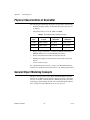
Physical Characteristics of DeviceNet .......................................................................... A-2
General Object Modeling Concepts .............................................................................. A-2
Object Modeling in the DeviceNet Specification.......................................................... A-4
Explicit Messaging Connections ................................................................................... A-5
I/O Connections............................................................................................................. A-7
Assembly Objects.......................................................................................................... A-12
NI-DNET User Manual
vi
ni.com
Contents
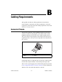
Appendix B
Cabling Requirements
Connector Pinouts..........................................................................................................B-1
Power Supply Information for the DeviceNet Ports ......................................................B-3
Cable Specifications ......................................................................................................B-6
Cable Lengths ................................................................................................................B-6
Maximum Number of Devices ......................................................................................B-6
Cable Termination .........................................................................................................B-7
Cabling Example............................................................................................................B-8
Appendix C
Troubleshooting and Common Questions
Troubleshooting with the Measurement & Automation Explorer (MAX) ....................C-1
Troubleshooting Self Test Failures................................................................................C-2
Common Questions........................................................................................................C-3
Appendix D
Hardware Specifications
Appendix E
Technical Support and Professional Services
Glossary
Index
© National Instruments
vii
NI-DNET User Manual
About This Manual
This manual describes the basics of DeviceNet and explains how to
develop an application program, including reference to examples. The
user manual also contains hardware information.
How to Use the Manual Set
Installation Guide
(CD Sleeve)
Software and
Hardware
Installation
First-Time
NI-DNET Users
NI-DNET
User Manual
Application
Development
and Examples
Experienced
NI-DNET Users
NI-DNET
Programmer
Reference Manual
Function
and Object
Descriptions
Use the installation guide to install and configure your DeviceNet hardware
and the NI-DNET software.
Use this NI-DNET User Manual to learn the basics of DeviceNet and how
to develop an application program. The user manual also contains
information on DeviceNet hardware.
Use the NI-DNET Programmer Reference Manual for specific information
about each NI-DNET function and object.
© National Instruments
ix
NI-DNET User Manual
About This Manual
Conventions
The following conventions appear in this manual:
»
The » symbol leads you through nested menu items and dialog box options
to a final action. The sequence Options»Settings»General directs you to
pull down the Options menu, select the Settings item, and select General
from the last dialog box.
This icon denotes a note, which alerts you to important information.
bold
Bold text denotes items that you must select or click in the software, such
as menu items and dialog box options. Bold text also denotes parameter
names.
italic
Italic text denotes variables, emphasis, a cross-reference, or an introduction
to a key concept. Italic text also denotes text that is a placeholder for a word
or value that you must supply.
monospace
Text in this font denotes text or characters that you should enter from the
keyboard, sections of code, programming examples, and syntax examples.
This font is also used for the proper names of disk drives, paths, directories,
programs, subprograms, subroutines, device names, functions, operations,
variables, filenames, and extensions.
monospace italic
Italic text in this font denotes text that is a placeholder for a word or value
that you must supply.
Related Documentation
The following documents contain information that you might find helpful
as you read this manual:
NI-DNET User Manual
•
ANSI/ISO Standard 11898-1993, Road Vehicles—Interchange of
Digital Information—Controller Area Network (CAN) for High-Speed
Communication
•
DeviceNet Specification, Version 2.0, Open DeviceNet Vendor
Association
•
CompactPCI Specification, Revision 2.0, PCI Industrial Computers
Manufacturers Group
•
PXI Hardware Specification, Revision 2.1, National Instruments
Corporation
x
ni.com
About This Manual
© National Instruments
•
PXI Software Specification, Revision 2.1, National Instruments
Corporation
•
LabVIEW online reference
•
ODVA website, www.odva.org
•
Microsoft Win32 Software Development Kit (SDK) online help
xi
NI-DNET User Manual
NI-DNET Software Overview
1
The DeviceNet software provided with National Instruments DeviceNet
hardware is called NI-DNET. This section provides an overview of the
NI-DNET software.
Installation and Configuration
Measurement & Automation Explorer (MAX)
Measurement & Automation Explorer (MAX) provides access to all of
your National Instruments products. Like other NI software products,
NI-DNET uses MAX as the centralized location for all configuration
and tools.
To launch MAX, select the Measurement & Automation shortcut on
your desktop, or within your Windows Programs menu under National
Instruments»Measurement & Automation.
For information about the NI-DNET software within MAX, consult the
MAX online help. A reference is in the MAX Help menu under
Help Topics»NI-DNET.
View help for items in the MAX Configuration tree by using the built-in
MAX help pane. If this help pane is not shown on the far right, select the
Show/Hide button in the upper right.
View help for a dialog box by selecting the Help button in the window.
The following sections provide an overview of some common tasks you
can perform within MAX.
© National Instruments
1-1
NI-DNET User Manual
Chapter 1
NI-DNET Software Overview
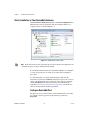
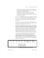
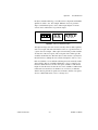
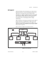
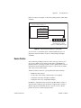
Verify Installation of Your DeviceNet Hardware
Within the Devices & Interfaces branch of the MAX Configuration tree,
NI DeviceNet cards are listed along with other hardware in the local
computer system, as shown in Figure 1-1.
Figure 1-1. NI-DNET Cards Listed in MAX
Each card’s name uses the word CAN, because the Controller Area Network is the
communication protocol upon which DeviceNet is built.
Note
If your NI DeviceNet hardware is not listed here, MAX is not configured
to search for new devices on startup. To search for the new hardware,
press <F5>.
To verify installation of your DeviceNet hardware, right-click the
DeviceNet card, then select Self-test. If the self-test passes, the card icon
shows a checkmark. If the self-test fails, the card icon shows an X mark,
and the Test Status in the right pane describes the problem. Refer to
Appendix C, Troubleshooting and Common Questions, for information
about resolving hardware installation problems.
Configure DeviceNet Port
The physical port of each DeviceNet card is listed under the card’s name.
To configure software properties, right-click the port and select
Properties.
NI-DNET User Manual
1-2
ni.com
Chapter 1
NI-DNET Software Overview
In the Properties dialog, you assign an interface name to the port, such as
DNET0 or DNET1. The interface name identifies the physical port within
NI-DNET APIs.
Change Protocol
To change the default protocol for the DeviceNet (CAN) card, right-click
the card and select Protocol. In this dialog you can select either DeviceNet
for NI-DNET (default), or CAN for NI-CAN. For more information, refer
to the section Using NI-CAN with NI-DNET.
LabVIEW Real-Time (RT) Configuration
LabVIEW Real-Time (RT) combines easy-to-use LabVIEW programming
with the power of real-time systems. When you use a National Instruments
PXI controller as a LabVIEW RT system, you can install a PXI DeviceNet
card and use the NI-DNET APIs to develop real-time applications. For
example, you can control a network of DeviceNet devices as a master, and
write your control algorithm in LabVIEW.
When you install the NI-DNET software, the installer checks for the
presence of the LabVIEW RT module. If LabVIEW RT exists, the
NI-DNET installer copies components for LabVIEW RT to your
Windows system. As with any other NI product for LabVIEW RT, you then
download the NI-DNET and NI-CAN software to your LabVIEW RT
system using the Remote Systems branch in MAX. For more information,
refer to the LabVIEW RT documentation.
After you have installed your PXI DeviceNet cards and downloaded the
NI-DNET software to your LabVIEW RT system, you need to verify
the installation. Within the Tools menu in MAX, select NI-DNET»
RT Hardware Configuration. The RT Hardware Configuration tool
provides features similar to Devices & Interfaces on your local system.
Use the RT Hardware Configuration tool to self-test the DeviceNet cards
and assign an interface name to each physical DeviceNet port.
© National Instruments
1-3
NI-DNET User Manual
Chapter 1
NI-DNET Software Overview
Tools
NI-DNET provides tools that you can launch from MAX.
Configurator
The Configurator is a powerful configuration tool with Electronic Data
Sheet (EDS) support. (EDS is a file on disk that contains configuration data
for specific device types. Each DeviceNet device has its own EDS file,
which is available from the device manufacturer.) The Configurator can
search a DeviceNet network to determine information about connected
devices, load the related EDS files automatically, read and write the device
parameters, and change a device MAC ID.
The Configurator helps you with the NI-DNET development by providing:
•
The device list and each device’s MAC ID, which are useful for
the NI-DNET ncOpenDnetIntf, ncOpenDnetExplMsg, and
ncOpenDnetIO functions.
•
Each device’s parameter list. You must import the device EDS file to
get the parameter list. You can also get each parameter’s ClassID/
InstanceID/AttributeID and type information, which are useful for
the NI-DNET ncGetDnetAttribute, ncSetDnetAttribute,
ncConvertFromDnetRead, and ncConvertForDnetWrite
functions.
•
Each device’s supported I/O connection and related help
information. You must import the device EDS file to get the help
information, which is useful for the NI-DNET ncOpenDnetIO,
ncConvertFromDnetRead, and ncConvertForDnetWrite
functions.
To launch the Configurator, right-click the DeviceNet interface (such as
DNET0) in MAX and select Configurator.
Analyzer
The Analyzer monitors the DeviceNet network and interprets the captured
CAN messages according to the DeviceNet protocol. It displays the
messages together with their parameters. You can display certain types
of messages using powerful filters and find options. You also can get
the message statistics in the Analyzer. The Analyzer is useful for
troubleshooting and analysis of DeviceNet networks and systems.
To launch the Analyzer, right-click the DeviceNet interface (such as
DNET0) in MAX and select Analyzer.
NI-DNET User Manual
1-4
ni.com
Chapter 1
NI-DNET Software Overview
NI I/O Trace
This tool monitors function calls to the NI-DNET APIs. This tool helps in
debugging programming problems in your application. To launch this tool,
open the Software branch of the MAX Configuration tree, right-click
NI I/O Trace, and select Launch NI I/O Trace.
NI-DNET Objects
The NI-DNET software, like the DeviceNet Specification, uses
object-oriented concepts to represent components in the DeviceNet system
(for more information about object-oriented concepts in the DeviceNet
Specification, refer to Appendix A, DeviceNet Overview). However,
whereas in the DeviceNet Specification objects represent a multitude
of components in DeviceNet devices, NI-DNET objects represent
components of the Windows device driver software. The NI-DNET device
driver objects do not correspond directly to objects contained in remote
devices. To facilitate access to the DeviceNet network, the NI-DNET
objects provide a more concise representation of various objects defined
in the DeviceNet Specification.
Much like any other object-oriented system, NI-DNET device driver
objects use the concepts of class, instance, attribute, and service to describe
their features. The NI-DNET device driver software provides three classes
of objects: Interface Objects, Explicit Messaging Objects, and I/O Objects.
You can open an instance of an NI-DNET object using one of the three
open functions (ncOpenDnetExplMsg, ncOpenDnetIntf, or
ncOpenDnetIO). The services for an NI-DNET object are accomplished
using the NI-DNET functions, which can be called directly from your
programming environment (such as Microsoft C/C++ or LabVIEW). The
essential attributes of an NI-DNET object are initialized using its open
function; you can access other attributes using ncGetDriverAttr or
ncSetDriverAttr. The attributes of NI-DNET device driver objects are
called driver attributes, to differentiate them from actual attributes in
remote DeviceNet devices.
For complete information on each NI-DNET object, including its driver
attributes and supported functions (services), refer to your NI-DNET
Programmer Reference Manual.
© National Instruments
1-5
NI-DNET User Manual
Chapter 1
NI-DNET Software Overview
Interface Object
The Interface Object represents a DeviceNet interface (physical DeviceNet
port on your DeviceNet board). Since this interface acts as a device on the
DeviceNet network much like any other device, it is configured with its
own MAC ID and baud rate.
Use the Interface Object to do the following:
•
Configure NI-DNET settings that apply to the entire interface
•
Start and stop communication for all NI-DNET objects associated with
the interface
Explicit Messaging Object
The Explicit Messaging Object represents an explicit messaging
connection to a remote DeviceNet device (physical device attached to
your interface by a DeviceNet cable). Since only one explicit messaging
connection is created for a given device, the Explicit Messaging Object is
also used for features that apply to the device as a whole.
Use the Explicit Messaging Object to do the following:
•
Execute the DeviceNet Get Attribute Single service on the remote
device (ncGetDnetAttribute)
•
Execute the DeviceNet Set Attribute Single service on the remote
device (ncSetDnetAttribute)
•
Send any other explicit message request to the remote device and
receive the associated explicit message response
(ncWriteDnetExplMsg, ncReadDnetExplMsg)
•
Configure NI-DNET settings that apply to the entire remote device
I/O Object
The I/O Object represents an I/O connection to a remote DeviceNet device
(physical device attached to your interface by a DeviceNet cable). The
I/O Object usually represents I/O communication as a master with a remote
slave device, but it can also be used for I/O communication as a slave.
The I/O Object supports as many master/slave I/O connections as currently
allowed by the DeviceNet Specification. This means that you can use
polled, strobed, and COS/cyclic I/O connections simultaneously for a given
device. As specified by the DeviceNet Specification, only one master/slave
I/O connection of a given type can be used for each device (MAC ID). For
example, you cannot open two polled I/O connections for the same device.
NI-DNET User Manual
1-6
ni.com
Chapter 1
NI-DNET Software Overview
Use the I/O Object to do the following:
•
Read data from the most recent message received on the
I/O connection (ncReadDnetIO)
•
Write data for the next message produced on the I/O connection
(ncWriteDnetIO)
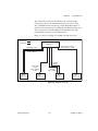
Example
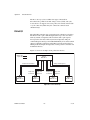
Figure 1-2 shows an example of how NI-DNET objects can be used to
communicate on a DeviceNet network. This example shows three
DeviceNet devices. The first device (at MAC ID 1) is the National
Instruments DeviceNet interface. The second device (at MAC ID 5) uses
NI-DNET to access a polled and a COS I/O connection simultaneously.
The third device (at MAC ID 8) uses NI-DNET to access an explicit
messaging connection and a strobed I/O connection.
Access to device at
MAC ID 5
I/O Object
Device MAC ID = 5
Connection Type = COS
Access to device at
MAC ID 8
I/O Object
Device MAC ID = 5
Connection Type = Poll
Explicit Messaging
Object
Device MAC ID = 8
I/O Object
Device MAC ID = 8
Connection Type = Strobe
Your National Instruments
DeviceNet Interface
Interface Object
Interface MAC ID = 1
Baud Rate = 500K
Figure 1-2. NI-DNET Objects for a Network of Three Devices
Using NI-CAN with NI-DNET
Controller Area Network (CAN) is the low-level protocol used for
DeviceNet communications. In addition to the NI-DNET functions, your
National Instruments DeviceNet hardware can also be used for low-level
access to CAN messages using the NI-CAN software. NI-CAN is intended
primarily for applications that require direct access to CAN messages, such
as test applications for automotive (non-DeviceNet) networks. When
© National Instruments
1-7
NI-DNET User Manual
Chapter 1
NI-DNET Software Overview
connecting to a DeviceNet network, the NI-CAN capabilities are useful for
the following applications:
•
Low-level monitoring of CAN messages to determine conformance to
DeviceNet specifications
•
Implementation of sections of the DeviceNet Specification yourself,
such as custom configuration tools
NI-CAN uses the same software infrastructure as NI-DNET, so both APIs
can be used with the same CAN card. The general rule is that each CAN
card can only be used for one API at a time.
Use of NI-DNET is restricted to port 1 (top port) of Series 1 CAN cards.
For more information on hardware provided in CAN kits, refer to
Chapter 2, NI-DNET Hardware Overview.
You can view each CAN card in MAX with either DeviceNet or CAN
features. To change the view of a CAN card in MAX, right-click the card
and select Protocol. In this dialog you can select either DeviceNet for
NI-DNET (default), or CAN for NI-CAN. When the CAN protocol is
selected, you can access CAN tools in MAX, such as the Bus Monitor tool
that displays CAN messages in their raw form.
In order to develop NI-CAN applications, you must install NI-CAN
components such as documentation and examples. The NI-CAN software
components are available within the NI-DNET installer.
Launch the setup.exe program for the NI-DNET installer in the same
manner as your original installation (CD or ni.com download). Within
the installer, select both NI-DNET and NI-CAN components in the
feature tree.
When you right-click a port in MAX and select Properties, the resulting
Interface selection uses the syntax CANx or DNETx based on your protocol
selection. Regardless of which protocol is selected, the number x is the only
relevant identifier with respect to NI-CAN and NI-DNET functions. For
example, if you select DNET0 as an interface in MAX, you can run an
NI-DNET application that uses DNET0, then you can run an NI-CAN
application that uses CAN0. Both applications refer to the same port,
and can run at different times, but not simultaneously.
NI-DNET User Manual
1-8
ni.com
NI-DNET Hardware Overview
2
Types of Hardware
The National Instruments DeviceNet hardware includes the PCI-CAN,
PXI-8461, and PCMCIA-CAN.
The PCI-CAN is software configurable and compliant with the PCI Local
Bus Specification. It features the National Instruments MITE bus interface
chip that connects the card to the PCI I/O bus. With a PCI-CAN, you can
make your PC-compatible computer with PCI Local Bus slots
communicate with and control DeviceNet devices.
The PXI-8461 is software configurable and compliant with the PXI
Specification and CompactPCI Specification. It features the National
Instruments MITE bus interface chip that connects the card to the PXI or
CompactPCI I/O bus. With a PXI-8461 card, you can make your PXI or
CompactPCI chassis communicate with and control DeviceNet devices.
PCMCIA-CAN hardware is a 16-bit, Type II PC Card that is software
configurable and compliant with the PCMCIA standards for 16-bit PC
cards. With a PCMCIA-CAN card, you can make your PC-compatible
notebook with PCMCIA slots communicate with and control DeviceNet
devices.
The PCI-CAN, PXI-8461, or PCMCIA-CAN in your DeviceNet kit is fully
compliant with the DeviceNet Specification.
All of the DeviceNet hardware uses the Intel 386EX embedded processor
to implement time-critical features provided by the NI-DNET software.
The cards communicate with the NI-DNET driver through on-board shared
memory and an interrupt.
The DeviceNet physical communication link protocol is based on the
Controller Area Network (CAN) protocol. The physical layers of the
PCI-CAN, PXI-8461, and PCMCIA-CAN fully conform to the DeviceNet
physical layer requirements. The physical layer is optically isolated to
500 V and is powered from the DeviceNet bus power supply. DeviceNet
interfacing is accomplished using the Intel 82527 CAN controller chip.
© National Instruments
2-1
NI-DNET User Manual
Chapter 2
NI-DNET Hardware Overview
For more information on the DeviceNet physical layer and cables used
to connect to your DeviceNet devices, refer to Appendix B, Cabling
Requirements.
For connection to the network, the PCI-CAN, PXI-8461, and
PCMCIA-CAN for DeviceNet provide combicon-style pluggable screw
terminals, as required by the DeviceNet Specification.
Differences Between CAN Kits and DeviceNet Kits
National Instruments provides hardware/software kits for both CAN and
DeviceNet. Since the CAN kits apply to a broad range of applications such
as automotive testing, the hardware in those kits offers a wide variety
of options. To ensure that the hardware product operates properly on a
DeviceNet network, we recommend that you purchase DeviceNet kits only.
The card provided in your DeviceNet kit can be used with both NI-DNET
and NI-CAN software.
Hardware in CAN kits is referenced as Series 2. Hardware in DeviceNet
kits is referenced as Series 1. Series 2 CAN cards cannot be used with the
NI-DNET software (NI-CAN only). The features of Series 2 CAN cards
are specifically designed for CAN applications, and provide no distinct
advantages for DeviceNet. For more information on Series 2 hardware,
refer to the hardware overview in the NI-CAN Hardware and Software
Manual.
Hardware in CAN kits offers 1-port and 2-port variants. NI-DNET operates
on one port only. If you use NI-DNET on a 2-port Series 1 CAN card, only
the top port can be used.
Hardware in CAN kits offer special transceivers (physical layer) such as
Low-Speed/Fault-Tolerant (LS) and Single-Wire (SW). Hardware in CAN
kits also offer the option to power the transceiver from the card, not the
network. These transceivers cannot be used with DeviceNet. Only
High-Speed (HS) transceivers comply with the DeviceNet specification.
Hardware in CAN kits use the DB-9 D-SUB connector. Hardware in
DeviceNet kits use the combicon-style connector from the DeviceNet
specification.
NI-DNET User Manual
2-2
ni.com
Developing Your Application
3
This chapter explains how to develop an application using the NI-DNET
functions.
Accessing NI-DNET from your Programming
Environment
Applications can access the NI-DNET driver software by using either
LabVIEW, LabWindows™/CVI™, Microsoft Visual C/C++,
Borland C/C++, or Visual Basic. If you are using any other development
environment, you must access the DNET library directly. Each of these
language interface techniques is summarized below.
LabVIEW
For applications written in LabVIEW, NI-DNET provides a complete
function library, front panel controls, and examples.
NI-DNET functions and controls are available in the LabVIEW palettes. In
LabVIEW 7.1 or later, the NI-DNET palette is located within the top-level
NI Measurements palette. In earlier LabVIEW versions, the NI-DNET
palette is located at the top-level.
The reference for each NI-DNET function is provided in the NI-DNET
Programmer Reference Manual. To access the reference for a function
from within LabVIEW, press <Ctrl-H> to open the help window, click
on the NI-DNET function, and then follow the link.
The NI-DNET software includes a full set of examples for LabVIEW.
These examples teach basic NI-DNET programming as well as advanced
topics. The example help describes each example and includes a link you
can use to open the VI. The NI-DNET example help is in Help»Find
Examples»Hardware Input and Output»DeviceNet.
© National Instruments
3-1
NI-DNET User Manual
Chapter 3
Developing Your Application
LabWindows/CVI
Within LabWindows/CVI, the NI-DNET function panel is located in
Library»NI-DNET. Like other LabWindows/CVI function panels, the
NI-DNET function panel provides help for each function and the ability to
generate code.
The reference for each NI-DNET function is provided in the NI-DNET
Programmer Reference Manual. You can access reference for each
function directly from within the function panel.
The header file for NI-DNET is nidnet.h. The library for NI-DNET is
nidnet.lib.
The NI-DNET software includes a full set of examples for
LabWindows/CVI. The NI-DNET examples are installed in the
LabWindows/CVI directory under samples\nidnet. Each example
provides a complete LabWindows/CVI project (.prj file). A description
of each example is provided in comments at the top of the .c file.
When you compile your LabWindows/CVI application for NI-DNET,
it is automatically linked with nidnet.lib, the link library for
LabWindows/CVI. When NI-DNET is installed, the installation program
checks to see which compatible C compiler you are using with
LabWindows/CVI (Microsoft or Borland), and copies an appropriate
nidnet.lib for that compiler.
Microsoft Visual Basic
To create an NI-DNET application in Visual Basic, add the nidnet.bas
file to your project. This allows you to call any NI-DNET function file from
your code.
The nidnet.bas file is located in the MS Visual Basic folder of the
NI-DNET folder. The typical path to this folder is \Program Files\
National Instruments\NI-DNET\MS Visual Basic.
The reference for each NI-DNET function is provided in the NI-DNET
Programmer Reference Manual, which you can open from Start»
All Programs»National Instruments»NI-DNET.
You can find examples for Visual Basic in the examples subfolder of the
MS Visual Basic folder. Each example is in a separate folder. A .vbp
file with the same name as the example opens the Visual Basic project.
A description of the example is located in a Help form within the project.
NI-DNET User Manual
3-2
ni.com
Chapter 3
Developing Your Application
Microsoft C/C++
The NI-DNET software supports Microsoft Visual C/C++ version 6.
The header file and library for Visual C/C++ 6 are in the MS Visual C
folder of the NI-DNET folder. The typical path to this folder is \Program
Files\National Instruments\NI-DNET\MS Visual C. To use
NI-DNET, include the nidnet.h header file in your code, then link with
the nidnetms.lib library file.
For C applications (files with a.c extension), include the header file by
adding a #include to the beginning of your code, as in:
#include "nidnet.h"
For C++ applications (files with .cpp extension), define _cplusplus
before including the header, such as:
#define _cplusplus
#include "nidnet.h"
The _cplusplus define enables the transition from C++ to the C language
NI-DNET functions.
The reference for each NI-DNET function is provided in the NI-DNET
Programmer Reference Manual, which you can open from Start»All
Programs»National Instruments»NI-DNET. You can find examples for
Visual C++ in the examples subfolder of the MS Visual C folder. Each
example is in a separate folder. A .c file with the same name as the
example contains a description the example in comments at the top of the
code. At the command prompt, after setting MSVC environment variables
(such as with MS vcvars32.bat), you can build each example using a
command such as:
cl –I.. singin.c ..\nidnetms.lib
Borland C/C++
The NI-DNET software supports Borland C/C++ version 5 or later.
The header file and library for Borland C/C++ are in the Borland C folder
of the NI-DNET folder. The typical path to this folder is \Program
Files\National Instruments\NI-DNET\Borland C.
To use NI-DNET, include the nidnet.h header file in your code, then link
with the nidnetbo.lib library file.
© National Instruments
3-3
NI-DNET User Manual
Chapter 3
Developing Your Application
For C applications (files with .c extension), include the header file by
adding a #include to the beginning of your code, like this:
#include "nidnet.h"
For C++ applications (files with .cpp extension), define _cplusplus
before including the header, such as:
#define _cplusplus
#include "nidnet.h"
The _cplusplus define enables the transition from C++ to the C language
NI-DNET functions.
The reference for each NI-DNET function is provided in the NI-DNET
Programmer Reference Manual, which you can open from Start»All
Programs»National Instruments»NI-DNET.
You can find examples for Visual C++ in the examples subfolder of the
Borland C folder. Each example is in a separate folder. A .c file with the
same name as the example contains a description the example in comments
at the top of the code.
Other Programming Languages
You can directly access NI-DNET from any programming environment
that allows you to request addresses of functions that a dynamic link library
(DLL) exports. The functions used to access a DLL in this manner are
provided by the Microsoft Win32 functions of Windows. Using these
Microsoft Win32 functions to access a DLL is often referred to as direct
entry. To use direct entry with NI-DNET, complete the following steps:
1.
Load the NI-DNET DLL, nican.dll.
The following C language code fragment illustrates how to call the
Win32 LoadLibrary function and check for an error.
#include <windows.h>
#include "nidnet.h"
HINSTANCE NidnetLib = NULL;
NidnetLib=LoadLibrary("nican.dll");
if (NidnetLib == NULL) {
return FALSE; /*Error*/
}
NI-DNET User Manual
3-4
ni.com
Chapter 3
2.
Developing Your Application
Get the addresses for the NI-DNET DLL functions you will use.
Your application must use the Win32 GetProcAddress function to
get the addresses of the NI-DNET functions your application needs.
For each NI-DNET function used by your application, you must define
a direct entry prototype. For the prototypes for each function exported
by nican.dll, refer to the NI-DNET Programmer Reference Manual.
The following code fragment illustrates how to get the addresses of the
ncOpenDnetIO, ncCloseObject, and ncReadDnetIO functions.
static NCTYPE_STATUS (_NCFUNC_ *PncOpenDnetIO)
(NCTYPE_STRING ObjName,
NCTYPE_OBJH_P ObjHandlePtr);
static NCTYPE_STATUS (_NCFUNC_ *PncCloseObject)
(NCTYPE_OBJH ObjHandle);
static NCTYPE_STATUS (_NCFUNC_ *PncReadDnetIO)
(NCTYPE_OBJH ObjHandle, NCTYPE_UINT32 SizeofData,
NCTYPE_ANY_P Data);
PncOpenDnetIO = (NCTYPE_STATUS (_NCFUNC_ *)
(NCTYPE_STRING, NCTYPE_OBJH_P))
GetProcAddress(NidnetLib,
(LPCSTR)"ncOpenDnetIO");
PncCloseObject = (NCTYPE_STATUS (_NCFUNC_ *)
(NCTYPE_OBJH))
GetProcAddress(NidnetLib,
(LPCSTR)"ncCloseObject");
PncRead = (NCTYPE_STATUS (_NCFUNC_ *)
(NCTYPE_OBJH, NCTYPE_UINT32, NCTYPE_ANY_P))
GetProcAddress(NidnetLib,
(LPCSTR)"ncReadDnetIO");
If GetProcAddress fails, it returns a NULL pointer. The following
code fragment illustrates how to verify that none of the calls to
GetProcAddress failed.
if ((PncOpenDnetIO == NULL) ||
(PncCloseObject == NULL) ||
(PncReadDnetIO == NULL)) {
FreeLibrary(NidnetLib);
printf("GetProcAddress failed");
}
© National Instruments
3-5
NI-DNET User Manual
Chapter 3
Developing Your Application
3.
Configure your application to de-reference the pointer to call an
NI-DNET function, as illustrated by the following code.
NCTYPE_STATUS status;
NCTYPE_OBJH MyObjh;
status = (*PncOpenDnetIO) ("DNET0", &MyObjh);
if (status < 0) {
printf("ncOpenDnetIO failed");
}
4.
Free nican.dll.
Before exiting your application, you need to free nican.dll with the
following command.
FreeLibrary(NidnetLib);
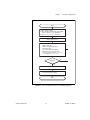
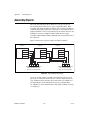
Programming Model for NI-DNET Applications
The following steps provide an overview of how to use the NI-DNET
functions in your application. The steps are shown in Figure 3-1 in
flowchart form. The NI-DNET functions are described in detail in the
NI-DNET Programmer Reference Manual.
NI-DNET User Manual
3-6
ni.com
Chapter 3
Developing Your Application
Start
1. Open Interface object
2. Open all I/O and Explicit Messaging (EM)
objects required for your application
3. Call ncSetDriverAttr, if needed
Start communication
Your DeviceNet Application:
• Write output data
• Wait for available input data
• Read input data
• Get or Set DeviceNet Attribute
• Open/Close any new I/O or EM
connection if the interface PollMode
is not equal to NC_POLL_AUTO
Finished?
No
Yes
Stop communication
1. Close I/O and EM objects.
2. Close the Interface object.
End
Figure 3-1. General Programming Steps for an NI-DNET Application
© National Instruments
3-7
NI-DNET User Manual
Chapter 3
Developing Your Application
Step 1. Open Objects
Before you use an NI-DNET object in your application, you must configure
and open it using either ncOpenDnetIntf, ncOpenDnetExplMsg, or
ncOpenDnetIO. These open functions return a handle for use in all
subsequent NI-DNET calls for that object.
The ncOpenDnetIntf function configures and opens an Interface Object.
Your NI-DNET application uses this Interface Object to start and stop
communication. The Interface Object must be the first NI-DNET object
opened by your application.
The ncOpenDnetExplMsg function configures and opens an Explicit
Messaging Object, and the ncOpenDnetIO function configures and opens
an I/O Object.
Step 2. Start Communication
Start communication to initialize DeviceNet connections to remote
devices. Use the Interface Object to call the ncOperateDnetIntf
function with the Opcode parameter set to Start.
The following optional steps can be done before you start communication:
NI-DNET User Manual
•
For an I/O Object, if it is not acceptable to send output data of all zeros,
call ncWriteDnetIO to provide valid output values for the initial
transmission.
•
For an I/O Object, if your application is multitasking, call the
ncCreateNotification function with the DesiredState
parameter set to Read Available. This notifies your application
when new input data is received from the remote device.
•
For any NI-DNET object, if any of the Driver attributes needs to be
changed, call ncSetDriverAttr with the attribute Id and attribute
value. The ncSetDriverAttr function cannot be called after the
communication has started.
3-8
ni.com
Chapter 3
Developing Your Application
Step 3. Run Your DeviceNet Application
After you open your NI-DNET objects and start communication, you are
ready to interact with the DeviceNet network.
Complete the following steps with an I/O Object:
1.
Call the ncWriteDnetIO function to write output data for subsequent
transmission on the DeviceNet network.
2.
Call the ncWaitForState function with the DesiredState
parameter set to Read Available. This function waits for output
data to be transmitted and for new input data to be received. If your
application is multitasking, you might have other tasks to do in
your application while you wait for new input data. If so, use the
ncCreateNotification function instead of ncWaitForState
(refer to Step 2. Start Communication).
3.
Call the ncReadDnetIO function to read input data received from the
DeviceNet network.
4.
Loop back to step 1 as needed.
Complete the following steps with an Explicit Messaging Object:
1.
2.
Call the ncWaitForState function with the DesiredState
parameter set to Established. This ensures that the explicit message
connection is established before you send the first explicit message
request.
To get an attribute from a remote DeviceNet device, call the
ncGetDnetAttribute function.
3.
To set the value of an attribute in a remote DeviceNet device, call the
ncSetDnetAttribute function.
© National Instruments
4.
To invoke other explicit message services in a remote DeviceNet
device, use the ncWriteDnetExplMsg function to write the service
request, the ncWaitForState function to wait for the service
response, and the ncReadDnetExplMsg function to read the service
response.
5.
Loop back to step 2 as needed.
3-9
NI-DNET User Manual
Chapter 3
Developing Your Application
Addition of Slave Connections after
Communication Start
If you need to add I/O and Explicit Messaging connections after
the communication on the network has started, you can call
ncOpenDnetExplMsg and ncOpenDnetIO as long as the Interface
Object’s poll mode had been configured to NC_POLL_SCAN (Scanned)
or NC_POLL_INDIV (Individual). Since the Automatic poll mode
(NC_POLL_AUTO) calculates the expected packet rate (EPR) based on the
estimated network bandwidth, all the I/O connections have to be opened
before you start the communication if the Automatic mode is selected. The
EPR restrictions due to different values of the PollMode parameter still
apply to the I/O objects. For details on these requirements, refer to
ncOpenDnetIO and ncOpenDnetIntf function descriptions in the
NI-DNET Programmer Reference Manual.
Step 4. Stop Communication
Before you exit your application, stop communication to shut down
DeviceNet connections to remote devices. Use the Interface Object to
call the ncOperateDnetIntf function with the Opcode parameter set
to Stop.
Step 5. Close Objects
Before you exit your application, close all NI-DNET objects using the
ncCloseObject function.
Multiple Applications on the Same Interface
The NI-DNET software allows multiple NI-DNET applications to use the
same interface object simultaneously, as long as the interface configuration
remains the same. For example, you can run both the SingleDevice
example and Configurator on DNET0 as long as the Interface MacId,
BaudRate, and PollMode parameters are the same in both applications
(Configurator uses a PollMode of Automatic). Similarly, you can open
up two copies of the SingleDevice example and communicate with two
different devices as if it were through a single application. These same rules
apply to the I/O Object and the Explicit Messaging Object.
As long as all the configuration attributes are the same, any object can
be opened multiple times. You can enable only one notification or wait
(through the ncCreateNotification or ncWaitForState functions)
for an object, no matter how many handles you have opened for that
NI-DNET User Manual
3-10
ni.com
Chapter 3
Developing Your Application
particular object. For example, if you are running two copies of the
SingleDevice example on the same interface with the same connection
types, the notification triggers in only one application at a time.
The synchronization of events and the protection of the object I/O data is
the responsibility of the application developer. Similarly, the application
performance might change based on the number of objects open and the
frequency of API calls made in each application. For example, several calls
to ncGetDnetAttribute in one application might slow down another
application running on the same interface.
To ensure proper clean up of all the objects, each open call to an object
should be matched by a close call to the same object, and each call to
ncOperateDnetIntf with NC_OP_START code should be matched by
a call to the same function with NC_OP_STOP code.
If you use two different applications on the same interface and open I/O
connections to different devices, you must set PollMode to either
Scanned or Individual. You cannot use PollMode of Automatic,
because that requires all I/O connections to be open prior to the first start
of communication.
Checking Status in LabVIEW
For applications written in LabVIEW, status checking is handled
automatically. For all NI-DNET functions, the lower left and right
terminals provide status information using LabVIEW Error Clusters.
LabVIEW Error Clusters are designed so that status information flows
from one function to the next, and function execution stops when an error
occurs. For more information, refer to the Error Handling section in the
LabVIEW online reference.
Within your LabVIEW block diagram, you wire the Error in and
Error out terminals of NI-DNET functions together in succession.
When an error is detected in an NI-DNET function (status field true),
all NI-DNET functions wired together are skipped except for
ncCloseObject. The ncCloseObject function executes regardless
of whether an error occurred, thus ensuring that all NI-DNET objects are
closed properly when execution stops due to an error. Depending on how
you want to handle errors, you can wire the Error in and Error out
terminals together per-object (group a single open/close pair), per-device
(group together Explicit Messaging and I/O Objects for a given device), or
per-network (group all functions for a given interface).
© National Instruments
3-11
NI-DNET User Manual
Chapter 3
Developing Your Application
As with any other LabVIEW error cluster, you can view error descriptions
using built-in LabVIEW features such as Explain Error in the Help menu,
or the Simple Error Handler VI in your diagram.
Checking Status in C, C++, and Visual Basic
Each C language NI-DNET function returns a value that indicates the status
of the function call. This status value is zero for success, greater than zero
for a warning, and less than zero for an error.
After every call to an NI-DNET function, your program should check to see
if the return status is nonzero. If so, call the ncStatusToString function
to obtain an ASCII string which describes the error/warning. You can then
use standard C function, such as printf, to display this ASCII string.
Your application code should check the status returned from every
NI-DNET function. If an error is detected, you should close all NI-DNET
handles, then exit the application. If a warning is detected, you can display
a message for debugging purposes, or simply ignore the warning.
For more information on status checking, refer to the ncStatusToString
function in the NI-DNET Programmer Reference Manual.
NI-DNET User Manual
3-12
ni.com
NI-DNET Programming
Techniques
4
This chapter describes various techniques to help you program your
NI-DNET application. The techniques include configuration of
I/O connection timing, using I/O data (assemblies), using explicit
messaging, and handling multiple devices.
Configuring I/O Connections
This section provides information on how I/O connections relate to one
another and how your configuration of I/O connection timing can affect the
overall performance of your DeviceNet system. The various types of
I/O connections provided by DeviceNet are described in Chapter 1,
NI-DNET Software Overview.
In a master/slave DeviceNet I/O system, the master determines the timing
of all I/O communication. Within your NI-DNET application, the
ncOpenDnetIO function configures the timing for I/O connections in
which your application communicates as master. As you read this section,
you might want to refer to the description of the ncOpenDnetIO function
in the NI-DNET Programmer Reference Manual.
Expected Packet Rate
Each DeviceNet I/O connection contains an attribute called the expected
packet rate, which specifies the expected rate (in milliseconds) of
messages (packets) for the I/O connection. For NI-DNET, you use the
ExpPacketRate parameter of the ncOpenDnetIO function to configure
the expected packet rate.
After you start communication, the embedded microprocessor on your
National Instruments DeviceNet interface transmits messages at the
ExpPacketRate. This means that after the I/O connection is configured,
your NI-DNET application does not need to be concerned with the timing
of messages on the DeviceNet network.
© National Instruments
4-1
NI-DNET User Manual
Chapter 4
NI-DNET Programming Techniques
When you select an ExpPacketRate for an I/O connection, you must
consider all I/O connections in your system. For example, although you
might be able to configure an ExpPacketRate of 3 ms for a single
I/O connection, you cannot configure a 3 ms ExpPacketRate for 40 I/O
connections because DeviceNet’s bandwidth capabilities cannot support
40 messages in a 3 ms time frame.
The following sections describe how to evaluate system considerations so
that you can configure valid values for ExpPacketRate.
Strobed I/O
For strobed I/O connections, the master broadcasts a single strobe
command message to all strobed slaves. Since all strobed I/O connections
transfer data at the rate of this single strobe command message, the
ExpPacketRate of each strobed I/O connection must be set to the
same value.
The common ExpPacketRate for all strobed I/O connections should
provide enough time for the strobe command and each strobed slave’s
response. You must also allow time for other I/O messages and explicit
messages to occur in the ExpPacketRate time frame. If you do not know
the time needed, let NI-DNET calculate a safe value for you (refer to the
section Automatic EPR Feature later in this chapter).
0 ms
5 ms
10 ms
15 ms
Strobe Command
Strobe Response 11
Strobe Response 12
StrobeResponse 13
Strobe Response 9
Strobe Command
Figure 4-1 shows a timing example for four strobed devices at MAC ID 9,
11, 12, and 13. Notice that since MAC ID 11 is slow to respond, the
ExpPacketRate is set to 20 ms to provide additional safety margin for
other messages.
20 ms
Figure 4-1. Strobed I/O Timing Example
NI-DNET User Manual
4-2
ni.com
Chapter 4
NI-DNET Programming Techniques
Polled I/O
Polled I/O connections use a separate poll command and response message
for each device.
The overall scheme that NI-DNET uses to time polled I/O connections
is determined by the PollMode parameter of ncOpenDnetIntf. This
PollMode parameter applies to all polled I/O connections (all calls to
ncOpenDnetIO with ConnectionType of Poll).
The following sections describe different schemes you can use for
polled I/O.
Scanned Polling
You can set the ExpPacketRate of each polled I/O connection to the same
value used for all strobed I/O. Using a common ExpPacketRate for all
strobed and polled I/O is referred to as scanned I/O. Scanned I/O is also
referred to as scanned polling with respect to polled I/O connections. When
you use scanned I/O, NI-DNET transmits all strobe and poll command
messages onto the network in quick succession.
Scanned I/O is a simple, efficient way to handle I/O connections that
require similar response rates. With scanned I/O, the master knows that all
strobe and poll commands go out at the same time. Therefore, the master
does not need to manage individual timers, thus optimizing processing
overhead. Scanned I/O also provides overall consistency. If a given
DeviceNet system uses only scanned I/O, you know that all higher level
control algorithms can execute at the single common strobe/poll
ExpPacketRate.
The common ExpPacketRate for all strobed and polled I/O connections
should provide enough time for all strobe/poll commands and each slave’s
response. You must also allow time for other I/O messages and explicit
messages to occur in the ExpPacketRate time frame.
NI-DNET provides two different methods you can use to configure
scanned I/O:
•
If you set the PollMode parameter of ncOpenDnetIntf to
Automatic, NI-DNET automatically calculates a valid common
ExpPacketRate value for each strobed and polled I/O connection.
When you use this scheme, you do not need to specify a valid
ExpPacketRate when you open your strobed/polled I/O connections.
For more information, refer to the Automatic EPR Feature section later
in this chapter.
© National Instruments
4-3
NI-DNET User Manual
Chapter 4
NI-DNET Programming Techniques
•
If you set the PollMode parameter of ncOpenDnetIntf to Scanned,
to configure scanned I/O you must specify the exact same
ExpPacketRate when you open each of your strobed/polled
I/O connections. Using this scheme, you must determine a valid
ExpPacketRate for your DeviceNet system.
0 ms
5 ms
10 ms
Poll Response 20
Poll Response 14
Poll Response 17
Poll Response 30
Poll Cmd 30
Poll Cmd 20
Poll Cmd 17
Poll Cmd 14
Figure 4-2 shows a scanned polling example for four polled devices at
MAC ID 14, 17, 20, and 30. The shaded areas indicate other message
traffic, such as the strobed I/O messages shown in Figure 4-1.
15 ms
20 ms
Figure 4-2. Scanned Polling Timing Example
Background Polling
Scanned polling can be less efficient when used with devices with
significantly different response times or devices with significantly different
rates of physical measurement. In the example above (Figure 4-2), consider
what would happen if device 14 took 52 ms to respond and device 20 took
38 ms to respond. In this case, even though device 17 and device 30
respond well within 20 ms, the common ExpPacketRate would need to
be at least 52 ms. This situation can often be avoided using a special case
of scanned polling called background polling.
To configure background polling, you first set the PollMode parameter of
ncOpenDnetIntf to Scanned. Then for each polled I/O connection you
configure (ncOpenDnetIO with ConnectionType set to Poll), you must
set ExpPacketRate to either a foreground rate or a background rate. The
foreground poll rate is the same as the common ExpPacketRate used for
all strobed I/O. Devices in this group generally respond quickly to poll
commands or have data that changes relatively quickly. The background
poll rate must be an exact multiple of the foreground poll rate. Devices in
this group generally respond slowly to poll commands or have data that
changes relatively slowly (such as temperature).
Background polling provides many of the same advantages as scanned
polling. The handling of only two groups optimizes performance. Also,
NI-DNET User Manual
4-4
ni.com
Chapter 4
NI-DNET Programming Techniques
background polling maintains overall network consistency because
NI-DNET evenly disperses all background poll commands among multiple
foreground cycles. In other words, all background poll commands are not
sent in quick succession and thus do not generate quick bursts of traffic on
the network.
0 ms
20 ms
40 ms
Blk Poll Cmd 14
Poll Cmd 30
Poll Cmd 17
Bkd Poll Response 20
Bkd Poll Response 14
Poll Response 17
Poll Response 30
Poll Cmd 30
Poll Cmd 17
Poll Response 30
Poll Response 17
Poll Cmd 17
Poll Cmd 30
Bkd Poll Cmd 20
Poll Response 17
Poll Response 30
Bkd Poll Cmd 14
Poll Cmd 30
Poll Cmd 17
Figure 4-3 shows a background polling example which resolves the
problem discussed previously. Devices at MAC ID 17 and 30 are
foreground polled every 20 ms (as before). Devices at MAC ID 14 and 20
are background polled every 60 ms (3 times the 20 ms foreground rate).
The shaded areas indicate other message traffic.
60 ms
Figure 4-3. Background Polling Timing Example
Individual Polling
When the underlying response rates of all polled I/O devices do not fit into
two clear groups, background polling can still be inefficient. For example,
assume you have four different polled I/O sensors capable of updating
measured input at 10 ms, 35 ms, 100 ms, and 700 ms respectively. Each
device responds to its poll command within 1 ms but measures data at a
different rate (such as a pushbutton for 10 ms and a temperature sensor for
700 ms). You could group these into a foreground rate of 10 ms and a
background rate of 700 ms, but then much DeviceNet bandwidth would be
wasted polling the 35 ms and 100 ms devices at the foreground rate. For
this situation, the individual polling scheme is most appropriate.
To configure individual polling, first set the PollMode parameter of
ncOpenDnetIntf to Individual. Then for each polled I/O connection
you configure (ncOpenDnetIO with ConnectionType set to Poll), you
must set ExpPacketRate to the rate desired for that device. Unlike the
scanned polling or background polling scheme, each poll command is no
longer associated with the strobe command’s rate, but instead is solely
based on its ExpPacketRate.
© National Instruments
4-5
NI-DNET User Manual
Chapter 4
NI-DNET Programming Techniques
Since the poll commands are not synchronized for individual polling, they
can often be scattered relatively randomly. They can be evenly interspersed
for a while, then suddenly occur in bursts of back-to-back messages.
Because of this inconsistency, you should use smaller MAC IDs for smaller
ExpPacketRate values. Since smaller MAC IDs in DeviceNet usually
gain access to the network before larger MAC IDs, this helps to ensure that
smaller rates can be maintained during bursts of increased traffic.
0 ms
20 ms
40 ms
60 ms
Poll Cmd 10
Poll Cmd 3
Poll Cmd 3
Poll Cmd 3
Poll Cmd 13
Poll Cmd 3
Poll Cmd 3
Poll Cmd 10
Poll Cmd 3
Poll Cmd 12
Poll Cmd 3
Poll Cmd 3
Poll Cmd 10
Poll Cmd 3
Figure 4-4 shows an individual polling example: MAC ID 3 is polled
every 10 ms, MAC ID 10 every 35 ms, MAC ID 12 every 100 ms, and
MAC ID 13 every 700 ms. Only the poll commands are shown (not poll
responses or other messages).
80 ms
Figure 4-4. Individual Polling Timing Example
Cyclic I/O
Cyclic I/O connections essentially use the same timing scheme as
individually polled I/O connections. Each cyclic I/O connection sends
its data at the configured ExpPacketRate. The main difference is that
cyclic I/O data is transferred from slave to master, rather than from master
to slave.
In the DeviceNet Specification, a poll command message is exactly the
same as a cyclic output message (master to slave data). Since cyclic data
from master to slave can be handled using individual polling, cyclic I/O
connections are more commonly used for input data from slave to master.
For NI-DNET, this means that for cyclic I/O connections, ncOpenDnetIO
is normally called with InputLength nonzero and OutputLength zero.
Just as for individually polled I/O, you should use smaller MAC IDs for
smaller cyclic I/O ExpPacketRate values. Doing so ensures that cyclic
I/O traffic is prioritized properly.
NI-DNET User Manual
4-6
ni.com
Chapter 4
NI-DNET Programming Techniques
Change-of-State (COS) I/O
Change-of-State I/O connections use the same timing scheme as cyclic I/O
connections, but in addition to the ExpPacketRate, COS I/O sends data
to the master whenever a change is detected.
For COS I/O, the cyclic transmission is used solely to verify that the
I/O connection still exists, so the ExpPacketRate is typically set to a large
value, such as 10,000 (10 seconds). Given such a large ExpPacketRate,
the main performance concerns for COS I/O are an appropriate MAC ID,
and if needed, a nonzero InhibitTimer.
In many cases, a given COS I/O device cannot detect data changes very
quickly. If a COS device is capable of detecting quickly changing data,
there is a chance that it could transmit many COS messages back-to-back,
precluding other I/O messages and thus dramatically impairing overall
DeviceNet performance. This problem is demonstrated in Figure 4-5.
Back to Back
COS I/O Data
Changing Frequently
COS I/O
0 ms
5 ms
10 ms
Some of the
Other I/O May
Have Timed Out
20 ms
15 ms
Figure 4-5. Congestion Due to Back-to-Back COS I/O
This problem can be prevented if you increase the MAC ID of the
frequently changing COS I/O device. If the COS device has a higher
MAC ID than other devices, it cannot preclude their I/O messages.
You can also prevent back-to-back COS I/O messages if you set the
InhibitTimer driver attribute using ncSetDriverAttr. After
transmitting COS data, the I/O connection must wait InhibitTimer
before it can transmit COS data again. A reasonable value for
InhibitTimer would be the smallest ExpPacketRate of an
I/O connection with a larger MAC ID than the COS I/O device.
Automatic EPR Feature
For cyclic I/O connections, a valid ExpPacketRate is required for
your call to ncOpenDnetIO. For COS I/O connections, a nonzero
ExpPacketRate is recommended for your call to ncOpenDnetIO but
can be set to a large value.
© National Instruments
4-7
NI-DNET User Manual
Chapter 4
NI-DNET Programming Techniques
For strobed and polled I/O connections, determination of a valid
ExpPacketRate can be somewhat complex. If you have trouble
estimating an ExpPacketRate value for strobed/polled I/O, set the
PollMode parameter of your initial call to ncOpenDnetIntf to
Automatic. When you use this automatic EPR feature, the
ExpPacketRate parameter of ncOpenDnetIO is ignored for
strobed/polled I/O (ConnectionType of Strobe or Poll), and NI-DNET
calculates a safe EPR value for you. This automatic EPR is the same for all
strobed and polled I/O connections (scanned I/O).
After you start communication, you can use the ncGetDriverAttr
function to determine the value calculated for ExpPacketRate. From that
value, you can then experiment with other ExpPacketRate configurations
using PollMode of Scanned or Individual.
The following information is used by NI-DNET to calculate a safe EPR:
•
NI-DNET assumes that it is the only master in your DeviceNet system.
•
The BaudRate parameter of ncOpenDnetIntf determines the time
taken for each message.
•
The InputLength and OutputLength parameters of each
ncOpenDnetIO determine the time needed for each I/O message.
•
NI-DNET assumes that each strobed/polled I/O device can respond to
its command within 2 ms.
•
NI-DNET sets aside a fixed amount of time for explicit messages. This
time depends on the baud rate.
Using I/O Data in Your Application
Appendix A, DeviceNet Overview, explains that the data transferred to and
from a DeviceNet device on an I/O connection is usually processed by an
Assembly Object within the slave device. Input assemblies represent the
data received by NI-DNET from a remote device, and output assemblies
represent data that NI-DNET transmits to a remote device.
To use a device’s I/O data within your application, you need to understand
the contents of its input and output assemblies. You can find this
information in the following places:
NI-DNET User Manual
•
Printed documentation provided by the device’s vendor.
•
If the device conforms to a standard device profile, the I/O assemblies
are defined within the DeviceNet Specification.
4-8
ni.com
Chapter 4
NI-DNET Programming Techniques
•
Some device vendors provide comments about I/O assemblies in an
Electronic Data Sheet (EDS). The EDS file is a text file whose format
is defined by the DeviceNet Specification.
•
Ask the device’s vendor if they have filled out a DeviceNet
compliance statement. This form is located at the front of the
DeviceNet Specification, and it provides information about the device,
including its I/O assemblies.
After you open an NI-DNET I/O Object and start communication, you use
the ncWriteDnetIO function to write an output assembly for a device and
the ncReadDnetIO function to read an input assembly received from a
remote device. Both of these functions access the entire assembly as an
array of bytes.
In most cases, the array of bytes for an input or output assembly contains
more than one value. In DeviceNet terminology, an individual data value
within an I/O assembly is referred to as a member.
Documentation for the members of an input or output assembly includes
the position of each member in the assembly (often shown as a table with
byte/bit offsets) and a listing of the attribute in the device that each member
represents (often shown as class, instance, and attribute identifiers). For
standard device profiles, the I/O assemblies are documented in the device
profile’s specification, and the actual attributes are documented in the
individual object specifications. Attribute documentation includes the
attribute’s DeviceNet data type and a complete explanation of its meaning.
As an example of I/O assembly documentation, consider the standard
AC Drive device profile. For this device profile, the DeviceNet
Specification defines an output assembly called Basic Speed Control
Output (Assembly Object instance 20). This output assembly is used to
start/stop forward motion at a given speed and to reset faults in the device.
The bytes of this output assembly are shown in Figure 4-6, and the attribute
mapping is shown in Table 4-1.
Byte
Bit 7
Bit 6
Bit 5
Bit 4
Bit 3
Bit 2
Bit 1
Bit 0
0
0
0
0
0
0
Fault Reset
0
Run Fwd
1
0
0
0
0
0
0
0
0
2
Speed Reference (Low Byte)
3
Speed Reference (High Byte)
Figure 4-6. AC Drive Output Assembly, Instance 20
© National Instruments
4-9
NI-DNET User Manual
Chapter 4
NI-DNET Programming Techniques
Table 4-1. Attribute Mapping for Basic Speed Control Output Assembly
Member
Name
Class
Name
Class ID
Instance ID
Attribute
Name
Attribute ID
Run
Fwd
Control
Supervisor
29 hex
1
Run1
3
Fault
Reset
Control
Supervisor
29 hex
1
FaultRst
12
Speed
Reference
AC/DC
Drive
2A hex
1
SpeedRef
8
By consulting the specifications for the Control Supervisor object and the
AC/DC Drive object, you can determine that the DeviceNet data type for
Run Fwd and Fault Reset is BOOL (boolean), and the DeviceNet data type
for Speed Reference is INT (16-bit signed integer).
Accessing I/O Members in LabVIEW
Many fundamental differences exist between the encoding of a DeviceNet
data type and its equivalent data type in LabVIEW. For example, for a
32-bit integer, the DeviceNet DINT data type uses Intel byte ordering
(lowest byte first), and the equivalent LabVIEW I32 data type uses
Motorola byte ordering (highest byte first).
To make it easier for you to avoid these data type issues in your
LabVIEW application, NI-DNET provides two functions to convert
between LabVIEW data types and DeviceNet data types:
ncConvertForDnetWrite and ncConvertFromDnetRead. These
functions are used to access individual members of an I/O assembly using
normal LabVIEW controls and indicators.
The following steps show an example of how you can use
ncConvertForDnetWrite to access the Basic Speed Control Output
Assembly described in the previous section:
NI-DNET User Manual
1.
Use the NI-DNET palette to place ncConvertForDnetWrite into
your diagram.
2.
Right-click on the DnetData in terminal and select Create
Constant, then initialize the first 4 bytes of the array to zero.
3.
Right-click on the DnetType terminal and select Create Constant,
then select BOOL from the enumeration.
4-10
ni.com
Chapter 4
NI-DNET Programming Techniques
4.
Right-click on the ByteOffset terminal and select Create Constant,
then enter 0 as the byte offset.
5.
Right-click on the 8[TF] in terminal and select Create Control. In
the front panel control that appears, you can use the button at index 0
to control Run Fwd and the button at index 2 to control Fault Reset.
6.
Using the NI-DNET palette, place ncConvertForDnetWrite into
your diagram.
7.
Wire the DnetData out terminal from the previous Convert into the
DnetData in terminal of this Convert.
8.
Right-click on the DnetType terminal and select Create Constant,
then select INT from the enumeration.
9.
Right-click on the ByteOffset terminal and select Create Constant,
then enter 2 as the byte offset.
10. Right-click on the I32/I16/I8 in terminal and select Create
Control. You can use the front panel control that appears to change
Speed Reference.
11. Using the NI-DNET palette, place ncWriteDnetIO into your
diagram.
12. Wire the DnetData out terminal from the previous Convert into the
Data terminal of ncWriteDnetIO.
For more information on the ncConvertForDnetWrite and
ncConvertFromDnetRead functions, refer to the NI-DNET Programmer
Reference Manual. For information on LabVIEW data types and their
equivalent DeviceNet data types, refer to Chapter 1, NI-DNET Data Types,
in the NI-DNET Programmer Reference Manual.
Accessing I/O Members in C
Since DeviceNet data types are very similar to C language data types,
individual I/O members can be accessed in a straightforward manner. You
can use the standard C language pointer manipulations to convert between
C language data types and DeviceNet data types.
© National Instruments
4-11
NI-DNET User Manual
Chapter 4
NI-DNET Programming Techniques
The following steps show an example of how standard C language can be
used to access the Basic Speed Control Output Assembly described in the
previous section.
1.
Declare an array of 4 bytes, as in the following.
NCTYPE_UINT8OutputAsm[4];
2.
Initialize the array to all zero.
for (I = 0; I < 4; I++)
OutputAsm [I] = 0;
3.
Assume you have two boolean variables, RunFwd and ResetFault,
of type NCTYPE_BOOL. For LabWindows/CVI, these variables could
be accessed from front panel buttons. The following code inserts these
boolean variables into OutputAsm.
if (RunFwd)
OutputAsm [0] |= 0x01;
if (FaultReset)
OutputAsm [0] |= 0x04;
4.
Assume you have an integer variable SpeedRef of type
NCTYPE_INT16. For LabWindows/CVI, this variable could be
accessed from a front panel control. The following code inserts this
integer variable into OutputAsm.
*(NCTYPE_INT16 *)(&( OutputAsm[2])) = SpeedRef;
5.
Write the output assembly to the remote device.
status = ncWriteDnetIO(objh, sizeof(OutputAsm),
OutputAsm);
For information on NI-DNET’s C language data types and their equivalent
DeviceNet data types, refer to Chapter 1, NI-DNET Data Types, of the
NI-DNET Programmer Reference Manual.
Using Explicit Messaging Services
The NI-DNET Explicit Messaging Object represents an explicit messaging
connection to a remote DeviceNet device. You use ncOpenDnetExplMsg
to configure and open an NI-DNET Explicit Messaging Object.
The following sections describe how to use the Explicit Messaging Object.
NI-DNET User Manual
4-12
ni.com
Chapter 4
NI-DNET Programming Techniques
Get and Set Attributes in a Remote DeviceNet Device
The two most commonly used DeviceNet explicit messages are the Get
Attribute Single service and the Set Attribute Single service. These services
are used to get or set the value of an attribute contained in a remote device.
The easiest way to execute the Get Attribute Single service on a remote
device is to use the NI-DNET ncGetDnetAttribute function. The
easiest way to execute the Set Attribute Single service on a remote device
is to use the NI-DNET ncSetDnetAttribute function.
For a given attribute of a DeviceNet device, you need the following
information to use the ncGetDnetAttribute or ncSetDnetAttribute
function:
•
The class and instance identifiers for the object in which the attribute
is located
•
The attribute identifier
•
The attribute’s DeviceNet data type
You can normally find this information from the object specifications
contained in the DeviceNet Specification, but many DeviceNet device
vendors also provide this information in the device’s documentation.
For the C programming language, the attribute’s DeviceNet data type
determines the corresponding NI-DNET data type you use to declare a
variable for the attribute’s value. For example, if the attribute’s DeviceNet
data type is INT (16-bit signed integer), you should declare a C language
variable of type NCTYPE_INT16, then pass the address of that variable
as the Attr parameter of the ncGetDnetAttribute or
ncSetDnetAttribute function.
For LabVIEW, the attribute’s DeviceNet data type determines
the corresponding LabVIEW data type to use with the
ncConvertForDnetWrite or ncConvertFromDnetRead functions. The
ncConvertFromDnetRead function converts a DeviceNet attribute read
using ncGetDnetAttribute into an appropriate LabVIEW data type. The
ncConvertForDnetWrite function converts a LabVIEW data type into an
appropriate DeviceNet attribute to write using ncSetDnetAttribute. For
more information on these LabVIEW conversion functions, refer to the
Using I/O Data in Your Application section.
© National Instruments
4-13
NI-DNET User Manual
Chapter 4
NI-DNET Programming Techniques
Other Explicit Messaging Services
To execute services other than Get Attribute Single and Set Attribute Single,
use the following sequence of function calls: ncWriteDnetExplMsg,
ncWaitForState, ncReadDnetExplMsg. The ncWriteDnetExplMsg
function sends an explicit message request to a remote DeviceNet device.
The ncWaitForState function waits for the explicit message response,
and the ncReadDnetExplMsg function reads that response.
Use ncWriteDnetExplMsg for such DeviceNet services as Reset, Save,
Restore, Get Attributes All, and Set Attributes All. Although the DeviceNet
Specification defines the overall format of these services, in most cases
their meaning and service data are object-specific or vendor-specific.
Unless your device requires such services and documents them in detail,
you probably do not need them for your application.
You need the following information to use the ncWriteDnetExplMsg and
ncReadDnetExplMsg functions for a given explicit messaging service:
•
The class and instance identifiers for the object to which the service
will be directed.
•
The service code used to identify the service.
•
The length and format of service request and response data. Some of
data formats are defined by the service’s overall specification (such as
in Appendix G, DeviceNet Explicit Services, in the DeviceNet
Specification manual), but many data formats are object-specific or
vendor-specific. For example, for the Reset service, Appendix G
defines the service’s code for use with any object, but its actual data
format is defined in the specification for the Identity Object.
•
The error codes that can be returned in the service response. Error
codes that are common to all services can be found in Appendix H,
DeviceNet Error Codes, in the DeviceNet Specification manual, but
many error codes are specific to the service, object, or vendor.
As with the ncGetDnetAttribute and ncSetDnetAttribute
functions, the service data formats for the request and response are
specified in terms of DeviceNet data types. These DeviceNet data types are
converted to/from the data types of your programming environment (C or
LabVIEW) as discussed in previous sections.
NI-DNET User Manual
4-14
ni.com
Chapter 4
NI-DNET Programming Techniques
Handling Multiple Devices
This section describes techniques you can use to efficiently implement an
application that communicates with a large number of DeviceNet devices.
In such an application, there might be only one call to ncOpenDnetIntf
(only one network), but there are usually multiple calls to ncOpenDnetIO
(and possibly ncOpenDnetExplMsg).
Configuration
If the configuration parameters used with ncOpenDnetIO tend to change
over time, you might want to organize them in data structures instead of
using constants.
For the C programming language, you can declare a structure typedef to
store the parameters of ncOpenDnetIO, similar to the following:
typedef struct {
NCTYPE_UINT32DeviceMacId;
NCTYPE_CONN_TYPEConnectionType;
NCTYPE_UINT32InputLength;
NCTYPE_UINT32OutputLength;
NCTYPE_UINT32ExpPacketRate;
} OpenDnetIO_Struct;
For LabVIEW, a cluster that contains these parameters is already defined
for use with ncOpenDnetIO.
You can use this structure/cluster to declare an array that contains
one entry for each call you make to ncOpenDnetIO. In LabVIEW and
LabWindows/CVI, you can use front panel controls to index through this
array and update configurations as needed.
In your code, write a For loop to index through the array and call
ncOpenDnetIO once for each array entry. This simplifies your code
because it does not contain a long list of sequential open calls, but instead
all open calls are combined into a concise loop.
© National Instruments
4-15
NI-DNET User Manual
Chapter 4
NI-DNET Programming Techniques
Object Handles
If you use an array to store configuration parameters for ncOpenDnetIO,
you can use this same scheme to store the ObjHandle returned by
ncOpenDnetIO. Within the For loop used for ncOpenDnetIO, you can store
the resulting ObjHandle into an array of object handles. Throughout your
code, you can index into this array to obtain the appropriate object handle.
Using an array of object handles is particularly useful in the LabVIEW
programming environment because it eliminates confusing routing of
individual object handle wires.
For applications with only a few object handles, another useful technique
for LabVIEW is to store each object handle in an indicator, then create a
local variable for each call that uses the handle. To create the indicator,
right-click on the ObjHandle out terminal and select Create Indicator.
To create a local variable, right-click on the indicator, select Create»Local
Variable, right-click on the local variable, and select Change To Read
Local. For more information on local variables, refer to the LabVIEW
online reference.
Main Loop
If your application essentially accesses all DeviceNet input/output data as
a single image, you would normally wait for read data to become available
on one of the input connections (such as a strobed I/O connection), read all
input data, execute your application code, then write all output data. The
wait is important because it helps to synchronize your application with the
overall DeviceNet network traffic.
In single-loop applications such as this, you normally set the PollMode
parameter of ncOpenDnetIntf to Automatic or Scanned so that all poll
command messages are sent out in quick succession.
Within a single-loop application, error handling is often done for the entire
application as a whole. In the C programming language, this means that
when an error is detected with any NI-DNET object, you display the error
and exit the application. In LabVIEW, this means that you wire all error
clusters of NI-DNET VIs together.
If your application uses different control code for different DeviceNet
devices, you might want to split your application into multiple tasks. You
can easily write a multitasking application by creating a notification for
the NI-DNET Read Avail state. This notification occurs when either
input data is available (to synchronize your code with each device’s
NI-DNET User Manual
4-16
ni.com
Chapter 4
NI-DNET Programming Techniques
I/O messages), or an error occurs. In the C programming language, you
create this notification callback using the ncCreateNotification
function. In LabVIEW, you use the ncWaitForState function.
In multiple-loop applications such as this, you normally set the PollMode
parameter of ncOpenDnetIntf to Individual so that each poll
command message can be sent out at its own individual rate.
Within a multiple-loop application, error handling is done separately for
each task. In the C programming language, this means that when an error
is detected, you handle it for the appropriate task, but you do not exit the
application. In LabVIEW, this means that you only wire the error clusters
of NI-DNET VIs that apply to each task, and thus you write different
sub-diagrams that are not wired together in any way.
© National Instruments
4-17
NI-DNET User Manual
DeviceNet Overview
A
This appendix gives an overview of DeviceNet.
History of DeviceNet
The Controller Area Network (CAN) was developed in the early 1980s by
Bosch, a leading automotive equipment supplier. CAN was developed to
overcome the limitations of conventional automotive wiring harnesses.
CAN connects devices such as engine controllers, anti-lock brake
controllers, and various sensors and actuators on a common serial bus.
By using a common pair of signal wires, any device on a CAN network can
communicate with any other device.
As CAN implementations became widespread throughout the automotive
industry, CAN was standardized internationally as ISO 11898, and major
semiconductor manufacturers such as Intel, Motorola, and Philips began
producing CAN chips. With these developments, many manufacturers of
industrial automation equipment began to consider other applications of
CAN technology. Automotive and industrial device networks showed
many similarities, including the transition away from dedicated signal
lines, low cost, resistance to harsh environments, and excellent real-time
capabilities.
In response to these similarities, Allen-Bradley developed DeviceNet, an
industrial networking protocol based on CAN. DeviceNet built on CAN’s
communication facilities to provide higher-level features which allow
industrial devices from different vendors to operate on the same network.
Soon after DeviceNet was developed, Allen-Bradley transferred the
specification to an independent organization called the Open DeviceNet
Vendor’s Association (ODVA). ODVA formally manages the DeviceNet
Specification and provides services to facilitate development of DeviceNet
devices and tools by various vendors. Due in large part to the efforts of
ODVA, hundreds of different vendors now provide DeviceNet products for
a wide range of applications.
© National Instruments
A-1
NI-DNET User Manual
Appendix A
DeviceNet Overview
Physical Characteristics of DeviceNet
The following list summarizes the physical characteristics of DeviceNet.
•
Trunkline-dropline cabling—main trunk cable with a drop cable for
each device
•
Selectable baud rates of 125 K, 250 K, and 500 K
Table A-1. DeviceNet Baud Rates and Wiring Lengths
Baud
Rate
Trunk
Length
Drop Length
Maximum
Drop Length
Cumulative
125 Kb/s
500 m (1640 ft)
6 m (20 ft)
156 m (512 ft)
250 Kb/s
250 m (820 ft)
6 m (20 ft)
78 m (256 ft)
500 Kb/s
100 m (328 ft)
6 m (20 ft)
39 m (128 ft)
•
Support for up to 64 devices—each device identifies itself using a
MAC ID (Media Access Control Identifier) from 0–63
•
Device removal/insertion without severing the network
•
Simultaneous support for both network-powered and self-powered
devices
•
Various connector styles
For complete information on how to connect your National Instruments
hardware onto the DeviceNet network, refer to your getting started manual.
General Object Modeling Concepts
The DeviceNet Specification uses object-oriented modeling to describe
the behavior of different components in a device, how those components
relate to one another, and how network communication takes place. The
following paragraphs briefly describe object-oriented modeling and how
these concepts are used within the DeviceNet Specification.
NI-DNET User Manual
A-2
ni.com
Appendix A
DeviceNet Overview
In object-oriented terminology, a classification of components with similar
qualities is called a class. For example, different classes of geometric
shapes could include squares, circles, and triangles. Figure A-1 shows
various classes and instances of geometric shapes.
1
2
3
1
Class Square
2
Class Triangle
1
2
3
4
Class Circle
Figure A-1. Classes of Geometric Shapes
All squares belong to the same class because they all have similar qualities,
such as four equal sides. The term instance refers to a specific instance of
a given class. For example, a blue square of four inches per side would be
one instance of the class square, and a red square of five inches per side
would be another instance. The term object is often used as a synonym for
the term instance, although in some contexts it might also refer to a class.
Each class defines a set of attributes which represent its externally visible
characteristics. The set of attributes defined by a class is common to all
instances within that class. For the class square, attributes could include
length of each side and color. For the class circle, attributes could include
radius and color. Each class also defines a set of services (or methods)
which is used to perform an operation on an instance. For the class square,
services could include resize, rotate, or change color.
© National Instruments
A-3
NI-DNET User Manual
Appendix A
DeviceNet Overview
Object Modeling in the DeviceNet Specification
Figure A-2 illustrates the object modeling used within the DeviceNet
Specification.
Application
Object(s)
Parameter
Object
Assembly
Object
Identity
Object
Message
Router
Explicit
Messaging
I/O
DeviceNet
Object
Connection
Objects
DeviceNet Network
Figure A-2. Object Modeling Used in DeviceNet Specification
Every DeviceNet device contains at least one instance (instance one) of
the Identity Object. The Identity Object instance defines attributes which
describe the device, including the device’s vendor, product name, and serial
number. The Identity Object also defines services which apply to the entire
device. For example, if you use the Reset service on instance one of the
Identity Object, the device resets to its power on state.
NI-DNET User Manual
A-4
ni.com
Appendix A
DeviceNet Overview
Another class of object contained in every DeviceNet device is the
Connection Object. Each instance of the Connection Object represents a
communication path to one or more devices. Attributes of each Connection
Object instance include the maximum number of bytes produced on the
connection, the maximum number of bytes consumed, and the expected
rate at which data is transferred.
In Figure A-2, the term Application Object(s) refers to objects within the
device which are used to perform its fundamental behavior. For example,
within a photoelectric sensor, an instance of the Presence Sensing object
(an Application Object) represents the physical photoelectric sensor
hardware. Within a position controller device, an instance of the Position
Controller object (an Application Object) is provided for every axis (motor)
which can be controlled using the device.
For more information on the classes, instances, attributes, and services
provided by DeviceNet, refer to the DeviceNet Specification. You can find
additional information on the specific classes and instances supported by a
given device in the documentation that came with the device.
Although the NI-DNET driver software provides object instances which
are used to access the DeviceNet network, these objects do not correspond
directly to the objects defined by the DeviceNet Specification, and the
NI-DNET functions do not directly correspond to the services defined by
DeviceNet. To facilitate access to your DeviceNet network, the features
provided by the NI-DNET driver are a simplification of the objects and
services defined in the DeviceNet Specification.
Explicit Messaging Connections
Each device on the DeviceNet network supports at least one explicit
messaging connection. Explicit messaging connections provide a
general-purpose communication path used to execute services on a
particular object in a device.
For a given explicit messaging connection between two DeviceNet devices,
the device requesting execution of the service is called the client, and the
device to which the service request is directed is called the server. Your
NI-DNET software can be used as an explicit messaging client with any
number of DeviceNet server devices.
Using an explicit messaging connection, the client device sends an explicit
message request to the server device. This request indicates the service to
perform and the object to which the service is directed. When the server
© National Instruments
A-5
NI-DNET User Manual
Appendix A
DeviceNet Overview
receives the explicit message request, it executes the service and sends an
explicit message response to the client device. If the service executed
successfully, this response contains information requested by the client.
The MAC ID (address) of the explicit message client and server is
contained in the header of the DeviceNet explicit messages.
The following tables describe the general format of DeviceNet explicit
message requests and responses as they appear on the DeviceNet network.
Table A-2. Explicit Message Request
Field
Description
Service Code
This number identifies the service requested by the client. The DeviceNet
Specification defines valid service codes.
Class ID
This number identifies the class to which the service is directed. The DeviceNet
Specification defines valid class IDs.
Instance ID
This number identifies the instance to which the service is directed. If the instance
ID is zero, the service is directed to the entire class. If the instance ID is one or
greater, the service is directed to a specific instance within the class.
Service Data
Data bytes specific to the Service Code. The number and format of these data
bytes is defined by the specification for the service.
Table A-3. Explicit Message Response
Field
Description
Service Code
This number indicates success or failure for execution of the service. If this
number is the same as the Service Code of the request, the service executed
successfully. If this number is 14 hex, the service failed to execute due to an error.
Service Data
If the service executed successfully, this field contains data bytes which are
specific to the Service Code. The number and format of these data bytes are
defined by the specification for the service.
If the service failed to execute, the first byte of Service Data contains a General
Error Code which describes the error, and the second byte contains an Additional
Error Code which qualifies the error. The DeviceNet Specification defines valid
values for the General Error Code and Additional Error Code.
The DeviceNet Specification defines a set of services supported in a
common way by different devices. These common services include Reset,
Save, Restore, Get Attribute Single, and Set Attribute Single.
NI-DNET User Manual
A-6
ni.com
Appendix A
DeviceNet Overview
The Get Attribute Single service obtains the value of a specific attribute
within a device’s object, and the Set Attribute Single service sets the value
of an attribute. These Get and Set services are the most commonly used
explicit messaging services. Since these two services are used often,
NI-DNET provides functions for these services: ncGetDnetAttribute
and ncSetDnetAttribute.
Other services defined by DeviceNet are used less often. For these services,
NI-DNET provides general purpose functions to send an explicit message
request (ncWriteDnetExplMsg) and receive an explicit message
response (ncReadDnetExplMsg). These NI-DNET functions use
parameters which are similar to the explicit message request/response
listed above. For more information on DeviceNet common services other
than Get/Set Attribute Single, refer to the DeviceNet Specification.
I/O Connections
In addition to explicit messaging connections, DeviceNet devices provide
another type of Connection Object called an I/O connection.
I/O connections provide a communication path for the exchange of
physical input/output (sensor/actuator) data as well as other
control-oriented data. I/O connections are useful for transferring data at
regular intervals.
Since many DeviceNet devices do not begin their normal operation until an
I/O connection is established, explicit messaging is often used for
configuration and initialization. For example, for a device with an analog
input, the I/O connection is normally used to read the analog input
measurement, and explicit messages are used for configuration such as
setting the measurement range and units (such as –10 to +10 V versus
4 to 20 mA).
The DeviceNet Specification defines two types of I/O connections:
master/slave and peer-to-peer. In master/slave I/O connections, a master
device uses an I/O connection to communicate with one or more slave
devices, and those slave devices can only communicate with the master and
not one another. In peer-to-peer I/O connections, each device on the
network can communicate as a peer, and communication paths between
peer devices are established as needed. The NI-DNET software currently
supports only master/slave I/O connections because the procedure used to
establish these I/O connections is more well defined. For this reason,
almost all existing DeviceNet devices only implement master/slave
I/O connections.
© National Instruments
A-7
NI-DNET User Manual
Appendix A
DeviceNet Overview
The DeviceNet Specification defines four types of master/slave
I/O connections: polled, bit strobed, change-of-state (COS), and cyclic.
A slave device can support at most one polled, one strobed, and one COS
or cyclic connection (COS and cyclic connections cannot be used
simultaneously).
Polled I/O
The polled I/O connection uses a request/response scheme for each device.
The master sends a poll command (request) message to the slave device
with any amount of output data. The slave then sends a poll response
message back to the master with any amount of input data. The poll
command/response messages are handled individually for each slave which
supports polled I/O connections. Polled I/O is typically used for devices
which provide both input and output data, such as position controllers and
modular I/O devices.
Figure A-3 shows an example of four polled slave devices.
Output data
Input data
Master
MAC ID = 1
12 Byte Poll Command
15 Byte Poll Response
6 Byte Poll Response
5 Byte Poll Command
2 Byte Poll
Command
Slave
MAC ID = 9
5 Byte Poll
Response
20 Byte Poll
Command
Slave
MAC ID = 11
3 Byte Poll
Response
Slave
MAC ID = 12
Slave
MAC ID = 13
Figure A-3. Polled I/O Example
NI-DNET User Manual
A-8
ni.com
Appendix A
DeviceNet Overview
Bit Strobed I/O
The (bit) strobed I/O connection is designed to move small amounts of
input data from the slave to its master. Strobed I/O is typically used for
simple sensors, such as photoelectric sensors and limit switches.
Strobed I/O is also called bit strobed I/O since the master sends a 64-bit
(8-byte) message containing a single bit of output data for each strobed
slave. This strobe command (request) message is received by all slave
devices simultaneously and can be used to trigger simultaneous
measurements (such as to take multiple photoelectric readings
simultaneously).
When a strobed slave receives the strobe command, it uses the output data
bit that corresponds to its own MAC ID (for example, the slave with
MAC ID 5 uses bit 5). Regardless of the value of its output bit, each
strobed slave responds to the command message by sending an individual
strobe message back to the master. The slave’s strobe response contains
from 0 to 8 bytes of input data.
Figure A-4 shows an example of four strobed slave devices.
Output data
Input data
Master
MAC ID = 1
4 Byte Strobe Response
1 Byte Strobe Response
6 Byte Strobe
Response
Slave
MAC ID = 9
2 Byte Strobe
Response
Slave
MAC ID = 11
Slave
MAC ID = 12
Slave
MAC ID = 13
8 Byte Strobe Command
0
1
2
9 10 11 12 13
Used
by 9
61 62 63
Used
by 12
Used Used
by 11 by 13
Figure A-4. Strobed I/O Example
© National Instruments
A-9
NI-DNET User Manual
Appendix A
DeviceNet Overview
Change-of-State and Cyclic I/O
The change-of-state (COS) and cyclic I/O connections both use the same
underlying communication mechanisms. Both transmit data at a fixed
interval called the expected packet rate (EPR). Since COS and cyclic
I/O connections use the same messaging on the DeviceNet network, they
are often referred to as a single I/O connection called COS/cyclic I/O.
The cyclic I/O connection enables a slave device to send input data to its
master at the configured EPR interval. You normally configure the EPR to
be consistent with the rate at which the device measures its physical input
sensors. For example, if a temperature sensor can take a measurement at
most once every 500 ms, you would configure the cyclic I/O connection’s
EPR as 500 ms. Cyclic I/O can be configured to send output data from
master to slave, but this configuration is seldom used since it is essentially
the same as polled I/O. Cyclic I/O messages can contain any amount
of data.
The COS I/O connection enables a slave device to send input data to its
master when a change is detected on its physical inputs. In addition to
sending input data when a change is detected, the COS slave also sends
its input data at a slower EPR interval that lets the master know it is still
functioning. COS I/O is typically used for devices with physical inputs that
can change frequently but can have the same input value for a long time.
For example, if a pushbutton device supports COS I/O, you might
configure its EPR as 3 seconds since the device sends a message
immediately if a button is pressed. COS I/O can be configured to send
output data from master to slave. Although master-to-slave COS output is
seldom used, it can be useful for things like front-panel pushbuttons which
are sent to a slave’s discrete outputs (such as LEDs and simple motors).
COS I/O messages can contain any amount of data.
When using COS/cyclic I/O connections, you can configure the device that
receives data to send an acknowledgment so that the transmitting device
can verify that the data was received successfully. For example, if you
configure slave-to-master COS I/O (input length nonzero), the master
sends an acknowledgment to the slave each time it receives an input
message. Since the acknowledgment message is used for verification
only, it does not contain data. If this verification can be handled using
other means (such as using strobed I/O to verify device status), the
acknowledgment message can be suppressed. For information on how to
suppress COS/cyclic acknowledgments using NI-DNET, refer to the
description of the I/O Object in the NI-DNET Programmer Reference
Manual.
NI-DNET User Manual
A-10
ni.com
Appendix A
DeviceNet Overview
Since COS and cyclic I/O use the same messages on the DeviceNet
network, they cannot be used simultaneously for a given slave device.
Also, polled I/O uses the same messages on the DeviceNet network as
master-to-slave output messages of COS/cyclic I/O. This means that a slave
device can use slave-to-master COS/cyclic I/O simultaneously with
polled I/O, but not master-to-slave COS/cyclic I/O.
Figure A-5 shows an example of four COS/cyclic I/O connections.
Output data
Input data
Master
MAC ID = 1
2 Byte Cyclic to Master
EPR = 500 ms, no ACK
COS ACK to Slave
4 Byte COS to Master
EPR = 200 ms
Cyclic ACK
to Master
6 Byte COS
to Slave
EPR = 400 ms,
no ACK
Slave
MAC ID = 9
12 Byte Cyclic
to Slave
EPR = 100 ms
Slave
MAC ID = 11
Slave
MAC ID = 12
Slave
MAC ID = 13
Figure A-5. COS/Cyclic I/O Example
© National Instruments
A-11
NI-DNET User Manual
Appendix A
DeviceNet Overview
Assembly Objects
One of the more important objects in the DeviceNet Specification is
the Assembly Object. There are two types of Assembly Object: input
assemblies and output assemblies. Assembly objects act like a switchboard,
routing incoming and outgoing data to its proper location within the device.
Output assemblies receive an output message from an I/O connection and
distribute its contents to multiple attributes within the slave. Input
assemblies gather multiple attributes within the slave for transmission on an
I/O connection.
Figure A-6 shows the operation of input and output assemblies.
Instance
Instance
Attributes
Instance
Attributes
Output Assembly, Associated
with an Output Message
Such as a Poll Command
Attributes
Input Assembly, Associated
with an Input Message
Such as a Poll Response
Figure A-6. Input and Output Assemblies
As a more specific example, consider a DeviceNet photoelectric sensor
(photoeye) or a limit switch. These devices contain a single instance of a
class called the Presence Sensing object. This instance has attributes for
the Output Signal (on/off) and Diagnostic Status (good/fault). These
two attributes are often routed through a single input assembly consisting
of a single byte.
NI-DNET User Manual
A-12
ni.com
Appendix A
DeviceNet Overview
Figure A-7 shows an example of a Presence Sensing instance and its input
assembly.
Presence Sensor Instance 1
Attributes
Output, BOOL
On Delay, UINT
Off Delay, UINT
Diagnostic, BOOL
Operate Mode, BOOL
0
0
0
0
0
0
Bit 7 6 5 4 3 2 1 0
One byte input assembly,
often returned as a strobe
response or COS input message.
Figure A-7. Input Assembly for Photoeye or Limit Switch
As you can see, to use the data bytes contained in I/O messages, it is
important to know the format of a device’s internal input and output
assemblies.
Device Profiles
To provide interoperability for devices of the same type, the DeviceNet
Specification defines various device profiles. The goal behind device
profiles is that for a given type of device, such as a photoelectric sensor, it
should be relatively straightforward to replace a sensor from one vendor
with a sensor from another vendor.
All devices which conform to a given profile must do the following:
•
Exhibit the same behavior
•
Use the same object model (certain instances are required)
•
Contain the same input and output assemblies
•
Contain the same set of configurable attributes
In addition to required features, most device profiles define a variety of
optional features. When an optional feature is supported by a vendor, it
must be supported as defined by the DeviceNet Specification. Device
profiles also allow for vendor-specific features.
© National Instruments
A-13
NI-DNET User Manual
Appendix A
DeviceNet Overview
The DeviceNet Specification provides device profiles for such devices as
photoelectric sensors, limit switches, motor starters, position controllers,
and mass-flow controllers.
Open DeviceNet Vendors Association (ODVA)
This chapter provides only a short summary of DeviceNet. For additional
information, such as a list of DeviceNet products and how to purchase the
DeviceNet Specification, refer to the ODVA Web site at www.odva.org.
NI-DNET User Manual
A-14
ni.com
B
Cabling Requirements
This appendix describes the cabling requirements for the hardware.
Cables should be constructed to meet these requirements as well as the
requirements of DeviceNet. DeviceNet cabling requirements can be found
in the DeviceNet Specification.
Connector Pinouts
The PCI-CAN, PXI-8461, and the PCMCIA-CAN bus-powered cable
each have a Combicon-style pluggable screw terminal connector. The
PCMCIA-CAN bus-powered cable also has a DB-9 D-SUB connector.
The 5-pin Combicon-style pluggable screw terminal follows the pinout
required by the DeviceNet Specification. Figure B-1 shows the pinout for
this connector.
4
5
3
2
1
1
2
V–
CAN_L
3
4
Shield
CAN_H
5
V+
Figure B-1. Pinout for 5-Pin Combicon-Style Pluggable Screw Terminal
CAN_H and CAN_L are signal lines that carry the data on the DeviceNet
network. These signals should be connected using twisted-pair cable.
The V+ and V– signals supply power to the DeviceNet physical layer. Refer
to Power Supply Information for the DeviceNet Ports for more information.
Shield is for the cable shield, which must be connected.
© National Instruments
B-1
NI-DNET User Manual
Appendix B
Cabling Requirements
V
+
S
H
C
_H
VC
_L
Figure B-2 shows the end of a PCMCIA-CAN bus-powered cable. The
arrow points to pin 1 of the 5-pin screw terminal block. All of the signals
on the 5-pin Combicon-style pluggable screw terminal are connected
directly to the corresponding pins on the 9-pin D-SUB following the pinout
in Figure B-3.
J1
J2
Figure B-2. PCMCIA-CAN Bus-Powered Cable
The 9-pin D-SUB follows the pinout recommended by CiA Draft
Standard 102. Figure B-3 shows the pinout for this connector.
1
2
3
4
No Connection
5
Shield
9
V+
V–
8
No Connection
CAN_L
7
CAN_H
No Connection
6
Optional Ground (V–)
Figure B-3. Pinout for 9-Pin D-SUB Connector
NI-DNET User Manual
B-2
ni.com
Appendix B
Cabling Requirements
Power Supply Information for the DeviceNet Ports
The bus must supply power to each DeviceNet port. The bus power supply
should be a DC power supply with an output of 10 V to 30 V. The
DeviceNet physical layer is powered from the bus using the V+ and V–
lines.
The power requirements for the DeviceNet port are shown in Table B-1.
You should take these requirements into account when determining the
requirements of the bus power supply for the system.
Table B-1. Power Requirements for the DeviceNet Physical Layer
for Bus-Powered Versions
Characteristic
Specification
Voltage Requirement
V+ 10 to 30 VDC
Current Requirement
40 mA typical
100 mA maximum
For the PCI-CAN, a jumper controls the source of power for the DeviceNet
physical layer. The location of this jumper is shown in Figure B-4.
1
2
3
4
1
2
Power Supply Jumper J6
Product Name
3
4
Serial Number
Assembly Number
Figure B-4. PCI-CAN Power Source Jumper
© National Instruments
B-3
NI-DNET User Manual
Appendix B
Cabling Requirements
The PCI-CAN is shipped with this jumper set in the EXT position. In this
position, the physical layer is powered from the bus (the V+ and V– pins
on the Combicon connector). The jumper must be in this position for the
DeviceNet interface to be compliant with the DeviceNet Specification.
If the DeviceNet interface is being used in a system where bus power is not
available, the jumper may be set in the INT position. In this position, the
physical layer is powered by the host computer. The physical layer is
still optically isolated. But under the settings, the PCI-CAN card is not
compliant with the DeviceNet specification. Figure B-5 shows how to
configure your jumpers for internal or external power supplies.
INT
3
2
EXT
1
a. Internal Power Mode
INT
3
2
EXT
1
b. External Power Mode
(DeviceNet)
Figure B-5. Power Source Jumpers
NI-DNET User Manual
B-4
ni.com
Appendix B
Cabling Requirements
For port one of the PXI-8461, power is configured with jumper J5. The
location of this jumper is shown in Figure B-6.
3
4
2
1
5
1
2
Power Supply Jumper J6
Power Supply Jumper J5
3
4
Assembly Number
Product Name
5
Serial Number
Figure B-6. PXI-8461 Parts Locator Diagram
Connecting pins 1 and 2 of a jumper configures the PXI-8461 physical
layer to be powered externally (from the bus cable power). In this
configuration, the power must be supplied on the V+ and V– pins on the
port connector. The jumper must be in this position for the DeviceNet
interface to be compliant with the DeviceNet Specification.
Connecting pins 2 and 3 of a jumper configures the PXI-8461 physical
layer to be powered internally (from the board). In this configuration, the
V– signal serves as the reference ground for the isolated signals.
The PCMCIA-CAN is shipped with the bus power version of the
PCMCIA-CAN cable. An internally-powered version of the
PCMCIA-CAN cable can be ordered from National Instruments.
© National Instruments
B-5
NI-DNET User Manual
Appendix B
Cabling Requirements
Cable Specifications
Cables should meet the requirements of the DeviceNet cable specification.
DeviceNet cabling requirements can be found in the DeviceNet
Specification.
Belden cable (3084A) meets all of those requirements and should be
suitable for most applications.
Cable Lengths
The allowable cable length is affected by the characteristics of the cabling
and the desired bit transmission rates. Detailed cable length requirements
can be found in the DeviceNet Specification.
Table B-2 lists the DeviceNet cable length specifications.
Table B-2. DeviceNet Cable Length Specifications
Baud Rate
Trunk Length
Drop Length
Maximum
Drop Length
Cumulative
500 kb/s
100 m (328 ft)
6 m (20 ft)
39 m (128 ft)
250 kb/s
250 m (820 ft)
6 m (20 ft)
78 m (256 ft)
125 kb/s
500 m (1640 ft)
6 m (20 ft)
156 m (512 ft)
Maximum Number of Devices
The maximum number of devices that you can connect to a DeviceNet port
depends on the electrical characteristics of the devices on the network. If
all of the devices on the network meet the DeviceNet specifications,
64 devices may be connected to the network.
NI-DNET User Manual
B-6
ni.com
Appendix B
Cabling Requirements
Cable Termination
The pair of signal wires (CAN_H and CAN_L) constitutes a transmission
line. If the transmission line is not terminated, each signal change on the
line causes reflections that may cause communication failures.
Because communication flows both ways on the DeviceNet bus, DeviceNet
requires that both ends of the cable be terminated. However, this
requirement does not mean that every device should have a termination
resistor. If multiple devices are placed along the cable, only the devices on
the ends of the cable should have termination resistors. Refer to Figure B-7
for an example of where termination resistors should be placed in a system
with more than two devices.
DeviceNet
Device
DeviceNet
Device
DeviceNet
Device
CAN_H
DeviceNet
Device
120 Ω
CAN_L
120 Ω
Figure B-7. Termination Resistor Placement
The termination resistors on a cable should match the nominal impedance
of the cable. DeviceNet requires a cable with a nominal impedance of
120 Ω; therefore, a 120 Ω resistor should be used at each end of the cable.
Each termination resistor should each be capable of dissipating at least
0.25 W of power.
© National Instruments
B-7
NI-DNET User Manual
Appendix B
Cabling Requirements
Cabling Example
Figure B-8 shows an example of a cable to connect two DeviceNet devices.
5-Pin
Combicon
9-Pin
D-Sub
Pin 4
Pin 7
Pin 2
Pin 2
Pin 3
Pin 5
Pin 5
Pin 9
Pin 1
Pin 3
CAN_H
120 Ω
9-Pin
D-Sub
5-Pin
Combicon
Pin 7
Pin 4
Pin 2
Pin 2
Pin 5
Pin 3
Pin 9
Pin 5
Pin 3
Pin 1
120 Ω
CAN_L
Shield
V+
V–
Power
Connector
V+
V–
Figure B-8. Cabling Example
NI-DNET User Manual
B-8
ni.com
Troubleshooting and
Common Questions
C
This appendix describes how to troubleshoot problems with the NI-DNET
software and answers some common questions.
Troubleshooting with the Measurement & Automation
Explorer (MAX)
MAX contains configuration information for all CAN (DeviceNet)
hardware installed on your system. To start MAX, double-click on the
Measurement & Automation icon on your desktop. Your CAN cards are
listed in the left pane (Configuration) under Devices and Interfaces»
NI-CAN Devices.
You can test your CAN cards by choosing Tools»NI-CAN»Test all Local
NI-CAN Cards from the menu, or you can right-click on a CAN card and
choose Self Test. If the Self Test fails, refer to the Troubleshooting Self Test
Failures section of this appendix.
Missing CAN Card
If you have a CAN card installed, but no CAN card appears in the
configuration section of MAX under Devices and Interfaces, you need to
search for hardware changes by pressing <F5> or choosing the Refresh
option from the View menu in MAX.
If the CAN card still doesn’t show up, you may have a resource conflict in
the Windows Device Manager. Refer to the documentation for your
Windows operating system for instructions on how to resolve the problem
using the Device Manager.
© National Instruments
C-1
NI-DNET User Manual
Appendix C
Troubleshooting and Common Questions
Troubleshooting Self Test Failures
The following topics explain common error messages generated by the Self
Test in MAX.
Application In Use
This error occurs if you are running an application that is using the
CAN card. The self test aborts to avoid adversely affecting your
application. Before running the self test, exit all applications that use
NI-DNET or NI-CAN. If you are using LabVIEW, you may need to exit
LabVIEW to unload the NI-DNET driver.
Memory Resource Conflict
This error occurs if the memory resource assigned to a CAN card conflicts
with the memory resources being used by other devices in the system.
Resource conflicts typically occur when your system contains legacy
boards that use resources not properly reserved with the Device Manager.
If a resource conflict exists, write down the memory resource that caused
the conflict and refer to the documentation for your Windows operating
system for instructions on how to use the Device Manager to reserve
memory resources for legacy boards. After the conflict has been resolved,
run the Self Test again.
Interrupt Resource Conflict
This error occurs if the interrupt resource assigned to a CAN card conflicts
with the interrupt resources being used by other devices in the system.
Resource conflicts typically occur when your system contains legacy
boards that use resources not properly reserved with the Device Manager.
If a resource conflict exists, write down the interrupt resource that caused
the conflict and refer to the documentation for your Windows operating
system for instructions on how to use the Device Manager to reserve
interrupt resources for legacy boards. After the conflict has been resolved,
run the Self Test again.
NI-CAN Software Problem Encountered
This error occurs if the Self Test detects that it is unable to communicate
correctly with the CAN hardware using the installed NI-CAN or NI-DNET
software. If you get this error, shut down your computer, restart it, and run
the Self Test again.
NI-DNET User Manual
C-2
ni.com
Appendix C
Troubleshooting and Common Questions
If the error continues after restart, uninstall NI-CAN (and NI-DNET) and
then reinstall.
NI-CAN Hardware Problem Encountered
This error occurs if the Self Test detects a defect in the CAN hardware. If
you get this error, write down the numeric code shown with the error and
contact National Instruments.
Common Questions
How can I determine which version of the NI-DNET software is
installed on my system?
Within MAX, open the Software branch and select NI-DNET. The version
is displayed in the right pane of MAX.
How many CAN cards can I configure for use with my NI-DNET
software?
The NI-DNET software can be configured to communicate with up to
32 CAN cards on all supported operating systems.
Which CAN hardware for DeviceNet does the NI-DNET software
support?
The NI-DNET software for supports Port 1, Series 1, High-Speed (HS)
cards. Although you can use 2-port CAN cards, only the top port can be
used with NI-DNET. For more information, refer to Chapter 2, NI-DNET
Hardware Overview.
Does NI-DNET support 2-port CAN cards?
Refer to the previous question.
Are interrupts required for the NI-CAN cards?
Yes, one interrupt per card is required. However, PCI and PXI CAN cards
can share interrupts with other devices in the system.
Does the CAN card provide power to the CAN bus?
No. To provide power to the CAN bus, you need an external power supply.
© National Instruments
C-3
NI-DNET User Manual
Appendix C
Troubleshooting and Common Questions
Can I use multiple PCMCIA cards in one computer?
Yes, but make sure there are enough free resources available. Unlike PCI
or PXI CAN cards, PCMCIA CAN cards cannot share resources, such as
IRQs, with other devices.
Why are some components left after the NI-DNET software is
uninstalled?
The uninstall program removes only items that the installation program
installed. If you add anything to a directory that was created by the
installation program, the uninstall program does not delete that directory,
because the directory is not empty after the uninstallation. You must
remove any remaining components yourself.
NI-DNET User Manual
C-4
ni.com
D
Hardware Specifications
This appendix describes the physical characteristics of the DeviceNet
hardware, along with the recommended operating conditions.
PCI-CAN Series
Dimensions............................................. 10.67 × 17.46 cm
(4.2 × 6.9 in.)
Power requirement ................................. +5 VDC, 775 mA typical
I/O connector.......................................... 5-pin Combicon-style pluggable
DeviceNet screw terminal
(high-speed CAN only)
Operating environment
Ambient temperature ...................... 0 to 55 °C
Relative humidity............................ 10 to 90%, noncondensing
Storage environment
Ambient temperature ...................... –20 to 70 °C
Relative humidity............................ 5 to 90%, noncondensing
PCMCIA-CAN Series
Dimensions............................................. 8.56 × 5.40 × 0.5 cm
(3.4 × 2.1 × 0.4 in.)
Power requirement ................................. 500 mA typical
I/O connector.......................................... Cable with 9-pin D-SUB and
pluggable screw terminal for
each port
Operating environment
Ambient temperature ...................... 0 to 55 °C
Relative humidity............................ 10 to 90%, noncondensing
© National Instruments
D-1
NI-DNET User Manual
Appendix D
Hardware Specifications
Storage environment
Ambient temperature .......................–20 to 70 °C
Relative humidity ............................5 to 90%, noncondensing
PXI-CAN Series
Dimensions .............................................16.0 × 10.0 cm
(6.3 × 3.9 in.)
Power requirement..................................+5 VDC, 775 mA typical
I/O connector ..........................................9-pin D-SUB for each port
(standard)
or
5-pin Combicon-style pluggable
DeviceNet screw terminal
(high-speed CAN only)
Operating environment
Ambient temperature .......................0 to 55 °C
Relative humidity ............................10 to 90%, noncondensing
Storage environment
Ambient temperature .......................–20 to 70 °C
Relative humidity ............................5 to 95%, noncondensing
(Tested in accordance with
IEC 60068-2-1, IEC-60068-2-2,
IEC-60068-2-56.)
Functional Shock ....................................30 g peak, half-sine, 11 ms pulse
(Tested in accordance with
IEC 60068-2-27. Test profile
developed in accordance with
MIL-T-28800E.)
Random Vibration
Operating .........................................5 to 500 Hz, 0.3 grms
Nonoperating ...................................5 to 500 Hz, 2.4 grms
(Tested in accordance with
IEC 60068-2-64. Nonoperating
test profile developed in
accordance with MIL-T-28800E
and MIL-STD-810E
Method 514.)
NI-DNET User Manual
D-2
ni.com
Appendix D
Hardware Specifications
Port Characteristics
Bus power .............................................. 0 to 30 V, 40 mA typical,
100 mA maximum
CAN-H, CAN-L..................................... –8 to +18 V, DC or peak, CATI
Safety
This product meets the requirements of the following standards of safety
for electrical equipment for measurement, control, and laboratory use:
•
IEC 61010-1, EN 61010-1
•
UL 61010-1, CSA 61010-1
Note For UL and other safety certifications, refer to the product label or the Online
Product Certification section.
Electromagnetic Compatibility
This product meets the requirements of the following EMC standards for
electrical equipment for measurement, control, and laboratory use:
•
EN 61326-1 (IEC 61326-1): Class A emissions; Basic immunity 1
•
EN 55011 (CISPR 11): Group 1, Class A emissions
•
AS/NZS CISPR 11: Group 1, Class A emissions
•
FCC 47 CFR Part 15B: Class A emissions
•
ICES-001: Class A emissions
For the standards applied to assess the EMC of this product, refer to the Online
Product Certification section.
Note
Note
For EMC compliance, operate this device with shielded cabling.
CE Compliance
This product meets the essential requirements of applicable European
Directives as follows:
© National Instruments
•
2006/95/EC; Low-Voltage Directive (safety)
•
2004/108/EC; Electromagnetic Compatibility Directive (EMC)
D-3
NI-DNET User Manual
Appendix D
Hardware Specifications
Online Product Certification
To obtain product certifications and the Declaration of Conformity (DoC)
for this product, visit ni.com/certification, search by model number
or product line, and click the appropriate link in the Certification column.
Environmental Management
NI is committed to designing and manufacturing products in an
environmentally responsible manner. NI recognizes that eliminating
certain hazardous substances from our products is beneficial to the
environment and to NI customers.
For additional environmental information, refer to the NI and the
Environment Web page at ni.com/environment. This page contains the
environmental regulations and directives with which NI complies, as well
as other environmental information not included in this document.
Waste Electrical and Electronic Equipment (WEEE)
At the end of their life cycle, all products must be sent to a WEEE recycling
center. For more information about WEEE recycling centers and National Instruments
WEEE initiatives, visit ni.com/environment/weee.htm.
EU Customers
⬉ᄤֵᙃѻક∵ᶧࠊㅵ⧚ࡲ⊩ ˄Ё RoHS˅
Ёᅶ᠋ National Instruments ヺড়Ё⬉ᄤֵᙃѻકЁ䰤ࠊՓ⫼ᶤѯ᳝ᆇ⠽䋼ᣛҸ (RoHS)DŽ
݇Ѣ National Instruments Ё RoHS ড়㾘ᗻֵᙃˈ䇋ⱏᔩ ni.com/environment/rohs_chinaDŽ
(For information about China RoHS compliance, go to ni.com/environment/rohs_china.)
NI-DNET User Manual
D-4
ni.com
Technical Support and
Professional Services
E
Log in to your National Instruments ni.com User Profile to get
personalized access to your services. Visit the following sections of
ni.com for technical support and professional services:
•
Support—Technical support at ni.com/support includes the
following resources:
–
Self-Help Technical Resources—For answers and solutions,
visit ni.com/support for software drivers and updates,
a searchable KnowledgeBase, product manuals, step-by-step
troubleshooting wizards, thousands of example programs,
tutorials, application notes, instrument drivers, and so on.
Registered users also receive access to the NI Discussion Forums
at ni.com/forums. NI Applications Engineers make sure every
question submitted online receives an answer.
–
Standard Service Program Membership—This program
entitles members to direct access to NI Applications Engineers
via phone and email for one-to-one technical support, as well as
exclusive access to eLearning training modules at ni.com/
elearning. All customers automatically receive a one-year
membership in the Standard Service Program (SSP) with the
purchase of most software products and bundles including
NI Developer Suite. NI also offers flexible extended contract
options that guarantee your SSP benefits are available without
interruption for as long as you need them. Visit ni.com/ssp for
more information.
For information about other technical support options in your
area, visit ni.com/services, or contact your local office at
ni.com/contact.
© National Instruments
•
Training and Certification—Visit ni.com/training for training
and certification program information. You can also register for
instructor-led, hands-on courses at locations around the world.
•
System Integration—If you have time constraints, limited in-house
technical resources, or other project challenges, National Instruments
E-1
NI-DNET User Manual
Appendix E
Technical Support and Professional Services
Alliance Partner members can help. To learn more, call your local
NI office or visit ni.com/alliance.
You also can visit the Worldwide Offices section of ni.com/niglobal
to access the branch office Web sites, which provide up-to-date contact
information, support phone numbers, email addresses, and current events.
NI-DNET User Manual
E-2
ni.com
Glossary
Symbol
Prefix
Value
m
milli
10 –3
k
kilo
10 3
A
A
amperes
AC
alternating current
actuator
A device that uses electrical, mechanical, or other signals to change
the value of an external, real-world variable. In the context of device
networks, actuators are devices that receive their primary data value from
over the network; examples include valves and motor starters. Also known
as final control element.
ANSI
American National Standards Institute
Application
Programming Interface
(API)
A collection of functions used by a user application to access hardware.
Within NI-DNET, you use API functions to make calls into the NI-DNET
driver.
ASCII
American Standard Code for Information Exchange
Assembly Object
Objects in DeviceNet devices which route I/O message contents to/from
individual attributes in the device.
attribute
The externally visible qualities of an object; for example, an instance
square of class Geometric Shapes could have the attributes length of sides
and color, with the values 4 in. and blue.
automatic polling
A polled I/O mode in which NI-DNET automatically determines an
appropriate scanned polling rate for your DeviceNet system.
© National Instruments
G-1
NI-DNET User Manual
Glossary
B
b
Bits
background polling
A polled I/O communication scheme in which all polled slaves are grouped
into two different communication rates: a foreground rate and a slower
background rate.
bit strobed I/O
Master/slave I/O connection in which the master broadcasts a single strobe
command to all strobed slaves then receives a strobe response from each
strobed slave.
C
CAN
Controller Area Network
change-of-state I/O
Master/slave I/O connection which is similar to cyclic I/O but data can be
sent when a change in the data is detected.
class
A classification of things with similar qualities.
client
In explicit messaging connections, the client is the device requesting
execution of the service.
common services
Services defined by the DeviceNet specification such that they are largely
interoperable.
connection
An association between two or more devices on a network that describes
when and how data is transferred.
controller
A device that receives data from sensors and sends data to actuators to hold
one or more external, real-world variables at a certain level or condition.
A thermostat is a simple example of a controller.
COS I/O
See change-of-state I/O.
cyclic I/O
Master/slave I/O connection in which the slave (or master) sends data at a
fixed interval.
NI-DNET User Manual
G-2
ni.com
Glossary
D
DC
direct current
device
A physical assembly, linked to a communication line (cable), capable of
communicating across the network according to a protocol specification.
device network
Multi-drop digital communication network for sensors, actuators, and
controllers.
device profiles
DeviceNet specifications which provide interoperability for devices of the
same type.
direct entry
Microsoft Win 32 functions used to directly access the functions of a
Dynamic Link Library (DLL).
DLL
Dynamic Link Library
driver attributes
Attributes of the NI-DNET driver software.
E
EDS
Electronic Data Sheet. Text file that describes DeviceNet device features
electronically.
expected packet rate
The rate (in milliseconds) at which a DeviceNet connection is expected to
transfer its data.
Explicit messaging
connection
General-purpose connection used for executing services on a particular
object in a DeviceNet device.
F
FCC
Federal Communications Commission
ft
feet
FTP
File transfer protocol
© National Instruments
G-3
NI-DNET User Manual
Glossary
H
hex
Hexadecimal
Hz
Hertz
I
I/O connection
Connection used for exchange of physical input/output (sensor/activator)
data, as well as other control-oriented data.
in.
inches
individual polling
A polled I/O communication scheme in which each polled slave
communicates at its own individual rate.
instance
A specific instance of a given class. For example, a blue square of 4 inches
per side would be one instance of the class Squares.
ISO
International Standards Organization
K
KB
Kilobytes of memory
L
LabVIEW
Laboratory Virtual Instrument Engineering Workbench
LED
light-emitting diode
local
Within NI-DNET, anything that exists on the same host (personal
computer) as the NI-DNET driver.
M
m
meter
MAC ID
Media access control layer identifier. In DeviceNet, a device’s MAC ID
represents its address on the DeviceNet network.
NI-DNET User Manual
G-4
ni.com
Glossary
master/slave
DeviceNet communication scheme in which a master device allocates
connections to one or more slave devices, and those slave devices can only
communicate with the master and not one another.
MB
Megabytes of memory
member
Individual data value within a DeviceNet I/O Assembly.
method
See service.
multi-drop
A physical connection in which multiple devices communicate with one
another along a single cable.
N
network interface
A device’s physical connection onto a network.
network management
utility
Utility used to manage configuration of DeviceNet devices.
network who
A search of a DeviceNet network to determine information about its
devices.
NI-DNET driver
Device driver and/or firmware that implement all the specifics of a
National Instruments DeviceNet interface.
notification
Within NI-DNET, an operating system mechanism that the NI-DNET
driver uses to communicate events to your application. You can think of a
notification of as an API function, but in the opposite direction.
O
object
See instance.
object-oriented
A software design methodology in which classes, instances, attributes, and
methods are used to hide all of the details of a software entity that do not
contribute to its essential characteristics.
ODVA
Open DeviceNet Vendor’s Association
© National Instruments
G-5
NI-DNET User Manual
Glossary
P
PC
personal computer
peer-to-peer
DeviceNet communication scheme in which each device communicates as
a peer and connections are established among devices as needed.
PLC
Programmable Logic Controller
polled I/O
Master/slave I/O connection in which the master sends a poll command to
a slave, then receives a poll response from that slave.
protocol
A formal set of conventions or rules for the exchange of information among
devices of a given network.
R
RAM
Random-access memory
remote
Within NI-DNET, anything that exists in another device of the device
network (not on the same host as the NI-DNET driver).
resource
Hardware settings used by National Instruments DeviceNet hardware,
including an interrupt request level (IRQ) and an 8 KB physical memory
range (such as D0000 to D1FFF hex).
S
s
seconds
scanned polling
A polled I/O communication scheme in which all poll commands are sent
out at the same rate, in quick succession.
sensor
A device that measures electrical, mechanical, or other signals from an
external, real-world variable; in the context of device networks, sensors are
devices that send their primary data value onto the network; examples
include temperature sensors and presence sensors. Also known as
transmitter.
server
In explicit messaging connections, the server is the device to which the
service is directed.
NI-DNET User Manual
G-6
ni.com
Glossary
service
An action performed on an instance to affect its behavior; the externally
visible code of an object. Within NI-DNET, you use NI-DNET functions
to execute services for objects. Also known as method and operation.
strobed I/O
See bit strobed I/O.
V
V
volts
VI
Virtual Instrument
VxD
Virtual device driver
© National Instruments
G-7
NI-DNET User Manual
Index
A
NI-CAN hardware problem
encountered, C-3
NI-CAN software problem
encountered, C-2
examples (NI resources), E-1
Analyzer, 1-4
C
change protocol, 1-3
common questions, C-3
and troubleshooting, C-1
components left after NI-CAN software
uninstall, C-4
determining NI-CAN software version, C-3
how many CAN interfaces can be
configured, C-3
interrupts required for NI-CAN cards, C-3
NI-CAN card and power to CAN bus, C-3
troubleshooting with MAX, C-1
using multiple PCMCIA cards, C-4
Configurator, 1-4
configure DNET port, 1-2
conventions used in the manual, x
H
help, technical support, E-1
I
installation and configuration
NI-DNET cards listed in MAX (figure), 1-2
verifying through MAX, 1-2
change protocol, 1-3
configure DNET port, 1-2
instrument drivers (NI resources), E-1
interrupt resource conflict, troubleshooting, C-2
K
KnowledgeBase, E-1
D
diagnostic tools (NI resources), E-1
documentation
conventions, x
how to use manual set, ix
NI resources, E-1
related conventions, x
drivers (NI resources), E-1
L
LabVIEW Real-Time (RT)
software configuration, 1-3
tools, 1-4
M
MAX
NI-DNET cards listed in MAX (figure), 1-2
tools launched from, 1-4
Measurement & Automation Explorer (MAX).
See MAX
E
error message
interrupt resource conflict,
troubleshooting, C-2
memory resource conflict, C-2
© National Instruments
I-1
NI-DNET User Manual
Index
specifications
PCI-CAN series board, D-1
PCMCIA-CAN series card, D-1
support, technical, E-1
memory resource conflict,
troubleshooting, C-2
missing CAN card, troubleshooting, C-1
N
T
National Instruments support
and services, E-1
NI I/O Trace, 1-5
NI-CAN hardware problem encountered,
troubleshooting, C-3
NI-CAN software problem encountered,
troubleshooting, C-2
NI-DNET, verify hardware installation in
MAX (figure), 1-2
technical support, E-1
training and certification (NI resources), E-1
troubleshooting
and common questions, C-1
interrupt resource conflict, C-2
memory resource conflict, C-2
missing CAN card, C-1
NI-CAN software problem
encountered, C-2, C-3
self-test failures, C-2
with MAX, C-1
troubleshooting (NI resources), E-1
P
PCI-CAN series board, specifications, D-1
PCMCIA-CAN series card,
specifications, D-1
port characteristics, D-3
programming examples (NI resources), E-1
PXI-8461
parts locator diagram (figure), B-5
port characteristics, D-3
W
Web resources, E-1
R
related documentation, x
S
self-test failures, troubleshooting, C-2
software
LabVIEW Real-Time (RT)
tools, 1-4
LabVIEW Real-Time (RT),
configuration, 1-3
NI resources, E-1
NI-DNET User Manual
I-2
ni.com