1
CAN
NI-CAN Hardware and Software Manual
TM
NI-CAN Hardware and Software Manual
October 2006
370289K-01
Support
Worldwide Technical Support and Product Information
ni.com
National Instruments Corporate Headquarters
11500 North Mopac Expressway
Austin, Texas 78759-3504
USA Tel: 512 683 0100
Worldwide Offices
Australia 1800 300 800, Austria 43 0 662 45 79 90 0, Belgium 32 0 2 757 00 20, Brazil 55 11 3262 3599,
Canada 800 433 3488, China 86 21 6555 7838, Czech Republic 420 224 235 774, Denmark 45 45 76 26 00,
Finland 385 0 9 725 725 11, France 33 0 1 48 14 24 24, Germany 49 0 89 741 31 30, India 91 80 41190000,
Israel 972 0 3 6393737, Italy 39 02 413091, Japan 81 3 5472 2970, Korea 82 02 3451 3400,
Lebanon 961 0 1 33 28 28, Malaysia 1800 887710, Mexico 01 800 010 0793, Netherlands 31 0 348 433 466,
New Zealand 0800 553 322, Norway 47 0 66 90 76 60, Poland 48 22 3390150, Portugal 351 210 311 210,
Russia 7 095 783 68 51, Singapore 1800 226 5886, Slovenia 386 3 425 4200, South Africa 27 0 11 805 8197,
Spain 34 91 640 0085, Sweden 46 0 8 587 895 00, Switzerland 41 56 200 51 51, Taiwan 886 02 2377 2222,
Thailand 662 278 6777, United Kingdom 44 0 1635 523545
For further support information, refer to the Technical Support and Professional Services appendix. To comment
on National Instruments documentation, refer to the National Instruments Web site at ni.com/info and enter
the info code feedback.
© 1996–2006 National Instruments Corporation. All rights reserved.
Important Information
Warranty
The CAN Hardware is warranted against defects in materials and workmanship for a period of one year from the date of shipment, as evidenced
by receipts or other documentation. National Instruments will, at its option, repair or replace equipment that proves to be defective during the
warranty period. This warranty includes parts and labor.
The media on which you receive National Instruments software are warranted not to fail to execute programming instructions, due to defects
in materials and workmanship, for a period of 90 days from date of shipment, as evidenced by receipts or other documentation. National
Instruments will, at its option, repair or replace software media that do not execute programming instructions if National Instruments receives
notice of such defects during the warranty period. National Instruments does not warrant that the operation of the software shall be
uninterrupted or error free.
A Return Material Authorization (RMA) number must be obtained from the factory and clearly marked on the outside of the package before
any equipment will be accepted for warranty work. National Instruments will pay the shipping costs of returning to the owner parts which are
covered by warranty.
National Instruments believes that the information in this document is accurate. The document has been carefully reviewed for technical
accuracy. In the event that technical or typographical errors exist, National Instruments reserves the right to make changes to subsequent
editions of this document without prior notice to holders of this edition. The reader should consult National Instruments if errors are suspected.
In no event shall National Instruments be liable for any damages arising out of or related to this document or the information contained in it.
EXCEPT AS SPECIFIED HEREIN, NATIONAL INSTRUMENTS MAKES NO WARRANTIES, EXPRESS OR IMPLIED, AND SPECIFICALLY DISCLAIMS ANY WARRANTY OF
MERCHANTABILITY OR FITNESS FOR A PARTICULAR PURPOSE. CUSTOMER’S RIGHT TO RECOVER DAMAGES CAUSED BY FAULT OR NEGLIGENCE ON THE PART OF
NATIONAL INSTRUMENTS SHALL BE LIMITED TO THE AMOUNT THERETOFORE PAID BY THE CUSTOMER. NATIONAL INSTRUMENTS WILL NOT BE LIABLE FOR
DAMAGES RESULTING FROM LOSS OF DATA, PROFITS, USE OF PRODUCTS, OR INCIDENTAL OR CONSEQUENTIAL DAMAGES, EVEN IF ADVISED OF THE POSSIBILITY
THEREOF. This limitation of the liability of National Instruments will apply regardless of the form of action, whether in contract or tort, including
negligence. Any action against National Instruments must be brought within one year after the cause of action accrues. National Instruments
shall not be liable for any delay in performance due to causes beyond its reasonable control. The warranty provided herein does not cover
damages, defects, malfunctions, or service failures caused by owner’s failure to follow the National Instruments installation, operation, or
maintenance instructions; owner’s modification of the product; owner’s abuse, misuse, or negligent acts; and power failure or surges, fire,
flood, accident, actions of third parties, or other events outside reasonable control.
Copyright
Under the copyright laws, this publication may not be reproduced or transmitted in any form, electronic or mechanical, including photocopying,
recording, storing in an information retrieval system, or translating, in whole or in part, without the prior written consent of National
Instruments Corporation.
National Instruments respects the intellectual property of others, and we ask our users to do the same. NI software is protected by copyright and other
intellectual property laws. Where NI software may be used to reproduce software or other materials belonging to others, you may use NI software only
to reproduce materials that you may reproduce in accordance with the terms of any applicable license or other legal restriction.
Trademarks
National Instruments, NI, ni.com, and LabVIEW are trademarks of National Instruments Corporation. Refer to the Terms of Use section
on ni.com/legal for more information about National Instruments trademarks.
Other product and company names mentioned herein are trademarks or trade names of their respective companies.
Members of the National Instruments Alliance Partner Program are business entities independent from National Instruments and have no
agency, partnership, or joint-venture relationship with National Instruments.
Patents
For patents covering National Instruments products, refer to the appropriate location: Help»Patents in your software, the patents.txt file
on your CD, or ni.com/patents.
WARNING REGARDING USE OF NATIONAL INSTRUMENTS PRODUCTS
(1) NATIONAL INSTRUMENTS PRODUCTS ARE NOT DESIGNED WITH COMPONENTS AND TESTING FOR A LEVEL OF
RELIABILITY SUITABLE FOR USE IN OR IN CONNECTION WITH SURGICAL IMPLANTS OR AS CRITICAL COMPONENTS IN
ANY LIFE SUPPORT SYSTEMS WHOSE FAILURE TO PERFORM CAN REASONABLY BE EXPECTED TO CAUSE SIGNIFICANT
INJURY TO A HUMAN.
(2) IN ANY APPLICATION, INCLUDING THE ABOVE, RELIABILITY OF OPERATION OF THE SOFTWARE PRODUCTS CAN BE
IMPAIRED BY ADVERSE FACTORS, INCLUDING BUT NOT LIMITED TO FLUCTUATIONS IN ELECTRICAL POWER SUPPLY,
COMPUTER HARDWARE MALFUNCTIONS, COMPUTER OPERATING SYSTEM SOFTWARE FITNESS, FITNESS OF COMPILERS
AND DEVELOPMENT SOFTWARE USED TO DEVELOP AN APPLICATION, INSTALLATION ERRORS, SOFTWARE AND
HARDWARE COMPATIBILITY PROBLEMS, MALFUNCTIONS OR FAILURES OF ELECTRONIC MONITORING OR CONTROL
DEVICES, TRANSIENT FAILURES OF ELECTRONIC SYSTEMS (HARDWARE AND/OR SOFTWARE), UNANTICIPATED USES OR
MISUSES, OR ERRORS ON THE PART OF THE USER OR APPLICATIONS DESIGNER (ADVERSE FACTORS SUCH AS THESE ARE
HEREAFTER COLLECTIVELY TERMED “SYSTEM FAILURES”). ANY APPLICATION WHERE A SYSTEM FAILURE WOULD
CREATE A RISK OF HARM TO PROPERTY OR PERSONS (INCLUDING THE RISK OF BODILY INJURY AND DEATH) SHOULD
NOT BE RELIANT SOLELY UPON ONE FORM OF ELECTRONIC SYSTEM DUE TO THE RISK OF SYSTEM FAILURE. TO AVOID
DAMAGE, INJURY, OR DEATH, THE USER OR APPLICATION DESIGNER MUST TAKE REASONABLY PRUDENT STEPS TO
PROTECT AGAINST SYSTEM FAILURES, INCLUDING BUT NOT LIMITED TO BACK-UP OR SHUT DOWN MECHANISMS.
BECAUSE EACH END-USER SYSTEM IS CUSTOMIZED AND DIFFERS FROM NATIONAL INSTRUMENTS' TESTING
PLATFORMS AND BECAUSE A USER OR APPLICATION DESIGNER MAY USE NATIONAL INSTRUMENTS PRODUCTS IN
COMBINATION WITH OTHER PRODUCTS IN A MANNER NOT EVALUATED OR CONTEMPLATED BY NATIONAL
INSTRUMENTS, THE USER OR APPLICATION DESIGNER IS ULTIMATELY RESPONSIBLE FOR VERIFYING AND VALIDATING
THE SUITABILITY OF NATIONAL INSTRUMENTS PRODUCTS WHENEVER NATIONAL INSTRUMENTS PRODUCTS ARE
INCORPORATED IN A SYSTEM OR APPLICATION, INCLUDING, WITHOUT LIMITATION, THE APPROPRIATE DESIGN,
PROCESS AND SAFETY LEVEL OF SUCH SYSTEM OR APPLICATION.
Compliance
Compliance with FCC/Canada Radio Frequency Interference
Regulations
Determining FCC Class
The Federal Communications Commission (FCC) has rules to protect wireless communications from interference. The FCC
places digital electronics into two classes. These classes are known as Class A (for use in industrial-commercial locations only)
or Class B (for use in residential or commercial locations). All National Instruments (NI) products are FCC Class A products.
Depending on where it is operated, this Class A product could be subject to restrictions in the FCC rules. (In Canada, the
Department of Communications (DOC), of Industry Canada, regulates wireless interference in much the same way.) Digital
electronics emit weak signals during normal operation that can affect radio, television, or other wireless products.
All Class A products display a simple warning statement of one paragraph in length regarding interference and undesired
operation. The FCC rules have restrictions regarding the locations where FCC Class A products can be operated.
Consult the FCC Web site at www.fcc.gov for more information.
FCC/DOC Warnings
This equipment generates and uses radio frequency energy and, if not installed and used in strict accordance with the instructions
in this manual and the CE marking Declaration of Conformity*, may cause interference to radio and television reception.
Classification requirements are the same for the Federal Communications Commission (FCC) and the Canadian Department
of Communications (DOC).
Changes or modifications not expressly approved by NI could void the user’s authority to operate the equipment under the
FCC Rules.
Class A
Federal Communications Commission
This equipment has been tested and found to comply with the limits for a Class A digital device, pursuant to part 15 of the FCC
Rules. These limits are designed to provide reasonable protection against harmful interference when the equipment is operated
in a commercial environment. This equipment generates, uses, and can radiate radio frequency energy and, if not installed and
used in accordance with the instruction manual, may cause harmful interference to radio communications. Operation of this
equipment in a residential area is likely to cause harmful interference in which case the user is required to correct the interference
at their own expense.
Canadian Department of Communications
This Class A digital apparatus meets all requirements of the Canadian Interference-Causing Equipment Regulations.
Cet appareil numérique de la classe A respecte toutes les exigences du Règlement sur le matériel brouilleur du Canada.
Compliance with EU Directives
Users in the European Union (EU) should refer to the Declaration of Conformity (DoC) for information* pertaining to the
CE marking. Refer to the Declaration of Conformity (DoC) for this product for any additional regulatory compliance
information. To obtain the DoC for this product, visit ni.com/certification, search by model number or product line,
and click the appropriate link in the Certification column.
* The CE marking Declaration of Conformity contains important supplementary information and instructions for the user or
installer.
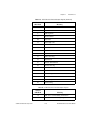
Contents
About This Manual
PCI-CAN .......................................................................................................................xv
PXI-846x ........................................................................................................................xv
PCMCIA-CAN ..............................................................................................................xv
USB-CAN ......................................................................................................................xvi
USB-LIN........................................................................................................................xvi
Conventions Used in This Manual.................................................................................xvii
Related Documentation..................................................................................................xvii
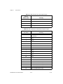
Chapter 1
Introduction
CAN Overview ..............................................................................................................1-1
Simplified CAN Data Frame ...........................................................................1-1
LIN Overview ................................................................................................................1-2
NI CAN Hardware Overview ........................................................................................1-2
About the NI CAN Series 2 Hardware ............................................................1-2
Series 2 Vs. Series 1 ........................................................................................1-4
PCI and PXI ......................................................................................1-6
PCMCIA ...........................................................................................1-7
PCMCIA Cables ...............................................................................1-7
About the USB-847x Hardware.......................................................................1-8
CAN: USB-8472, USB-8472s, USB-8473, USB-8473s...................1-8
LIN: USB-8476, USB-8476s ............................................................1-9
NI-CAN Software Overview .........................................................................................1-9
MAX................................................................................................................1-9
Frame API .......................................................................................................1-10
Channel API ....................................................................................................1-10
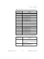
Chapter 2
Installation and Configuration
Safety Information .........................................................................................................2-1
Measurement & Automation Explorer (MAX) .............................................................2-3
Verify Installation of CAN and LIN Hardware .............................................................2-3
Configure CAN and LIN Ports........................................................................2-4
CAN Channels.................................................................................................2-5
LabVIEW Real-Time (RT) Configuration ....................................................................2-6
PXI System......................................................................................................2-6
CompactRIO System .......................................................................................2-7
© National Instruments Corporation
v
NI-CAN Hardware and Software Manual
Contents
Tools .............................................................................................................................. 2-7
Using NI-CAN with NI-DNET ..................................................................................... 2-8
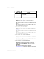
Chapter 3
NI CAN and LIN Hardware
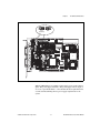
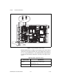
Philips SJA1000 CAN Controller ................................................................................. 3-1
PCI-CAN ....................................................................................................................... 3-2
High-Speed Physical Layer............................................................................. 3-2
Transceiver ....................................................................................... 3-2
Bus Power Requirements.................................................................. 3-2
VBAT Jumper................................................................................... 3-2
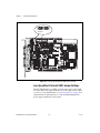
Low-Speed/Fault-Tolerant Physical Layer ..................................................... 3-4
Transceiver ....................................................................................... 3-4
Bus Power Requirements.................................................................. 3-5
VBAT Jumper................................................................................... 3-5
Low-Speed/Fault-Tolerant VBAT Jumper Settings ......................... 3-6
Single Wire Physical Layer............................................................................. 3-7
Transceiver ....................................................................................... 3-7
Bus Power Requirements.................................................................. 3-7
VBAT Jumper................................................................................... 3-8
XS Software Selectable Physical Layer.......................................................... 3-8
RTSI ............................................................................................................... 3-9
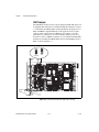
PXI-846x........................................................................................................................ 3-11
High-Speed Physical Layer............................................................................. 3-11
Transceiver ....................................................................................... 3-11
Bus Power Requirements.................................................................. 3-11
VBAT Jumper................................................................................... 3-11
Low-Speed/Fault-Tolerant Physical Layer ..................................................... 3-13
Transceiver ....................................................................................... 3-13
Bus Power Requirements.................................................................. 3-13
VBAT Jumper................................................................................... 3-14
Single Wire Physical Layer............................................................................. 3-15
Transceiver ....................................................................................... 3-15
Bus Power Requirements.................................................................. 3-16
VBAT Jumper................................................................................... 3-16
XS Software Selectable Physical Layer.......................................................... 3-16
PXI Trigger Bus (RTSI)................................................................................. 3-18
PCMCIA-CAN .............................................................................................................. 3-20
PCMCIA-CAN High-Speed Cables................................................................ 3-20
Transceiver ....................................................................................... 3-20
Bus Power Requirements.................................................................. 3-20
NI-CAN Hardware and Software Manual
vi
ni.com
Contents
PCMCIA-CAN Low-Speed/Fault-Tolerant Cables ........................................3-21
Transceiver........................................................................................3-21
Bus Power Requirements ..................................................................3-21
PCMCIA-CAN Single Wire Cables................................................................3-22
Transceiver........................................................................................3-22
Bus Power Requirements ..................................................................3-22
Synchronization ................................................................................3-23
USB-CAN ......................................................................................................................3-25
USB-8473/USB-8473s: High-Speed Physical Layer ......................................3-25
Transceiver........................................................................................3-26
Bus Power Requirements ..................................................................3-26
LED Indicators..................................................................................3-26
USB-8472/USB-8472s: Low-Speed/Fault-Tolerant Physical Layer...............3-27
Transceiver........................................................................................3-27
Bus Power Requirements ..................................................................3-27
LED Indicators..................................................................................3-28
USB-LIN........................................................................................................................3-28
USB-8476/USB-8476s: LIN ...........................................................................3-28
Transceiver........................................................................................3-28
Bus Power Requirements ..................................................................3-28
LED Indicators..................................................................................3-29
Synchronization in USB-CAN/LIN Devices .................................................................3-29
CAN for CompactRIO ...................................................................................................3-32
What is CompactRIO?.....................................................................................3-32
NI 985x............................................................................................................3-32
Chapter 4
Connectors and Cables
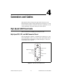
High-Speed CAN Pinout Cable .....................................................................................4-1
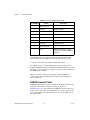
High-Speed PCI, PXI, and USB Connector Pinout.........................................4-1
PCMCIA Connector Pinout ..............................................................4-2
Cabling Requirements for High-Speed CAN....................................4-4
Cable Lengths ...................................................................................4-4
Number of Devices ...........................................................................4-5
Cable Termination.............................................................................4-5
Cabling Example...............................................................................4-6
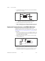
Low-Speed/Fault-Tolerant CAN Pinout Cable..............................................................4-6
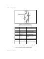
Low-Speed/Fault-Tolerant PCI, PXI, and USB Connector Pinout .................4-6
PCMCIA Connector Pinout PCMCIA Connector Pinout.................4-8
Cabling Requirements for Low-Speed/Fault-Tolerant CAN ..........................4-9
Number of Devices ...........................................................................4-9
Termination .......................................................................................4-10
© National Instruments Corporation
vii
NI-CAN Hardware and Software Manual
Contents
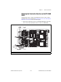
Determining the Necessary Termination Resistance
for the Board .................................................................................. 4-10
Software Selectable Termination (USB-8472s only) ....................... 4-13
Replacing the Termination Resistors on Your
PCI-CAN/LS Board....................................................................... 4-13
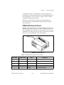
Replacing the Termination Resistors on the PXI-8460 Board ......... 4-15
Replacing the Termination Resistors on the PCMCIA-CAN/LS Cable ......... 4-16
Cabling Example .............................................................................. 4-17
Single Wire CAN Pinout Cable..................................................................................... 4-17
Single Wire PCI and PXI Connector Pinout ................................................... 4-17
PCMCIA-CAN Connector Pinout .................................................... 4-19
Cabling Requirements for Single Wire CAN ................................................. 4-20
Cable Length..................................................................................... 4-20
Number of Devices ........................................................................... 4-20
Termination (Bus Loading) .............................................................. 4-20
Cabling Example .............................................................................. 4-21
XS CAN Pinout Cable................................................................................................... 4-21
XS PCI and PXI Connector Pinout ................................................................. 4-21
Cabling Requirements for XS CAN................................................................ 4-23
External Transceiver Example.......................................................... 4-24
LIN ................................................................................................................................ 4-24
USB-LIN Connector Pinout............................................................................ 4-24
Cabling Requirements for LIN Specifications (LIN) ..................................... 4-26
Cable Specifications ......................................................................... 4-26
Cable Lengths ................................................................................... 4-26
Number of Devices ........................................................................... 4-26
Termination ...................................................................................... 4-26
Chapter 5
Application Development
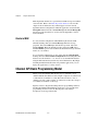
Choose the Programming Language ............................................................................. 5-1
LabVIEW ........................................................................................................ 5-1
LabWindows/CVI ........................................................................................... 5-2
Visual C++ 6 ................................................................................................... 5-2
Borland C/C++................................................................................................ 5-3
Microsoft Visual Basic.................................................................................... 5-4
Other Programming Languages ...................................................................... 5-4
Choose Which API To Use ........................................................................................... 5-6
NI-CAN Hardware and Software Manual
viii
ni.com
Contents
Chapter 6
Using the Channel API
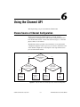
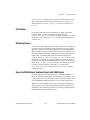
Choose Source of Channel Configuration .....................................................................6-1
Already Have a CAN Database File?..............................................................6-2
Application Uses a Subset of Channels? .........................................................6-2
Import CAN Database into MAX....................................................................6-2
Access CAN Database within Application......................................................6-3
User Must Create within Application? ............................................................6-3
Use Create Message Function in Application .................................................6-3
Create in MAX ................................................................................................6-4
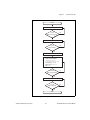
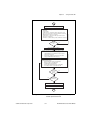
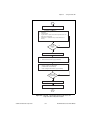
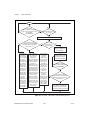
Channel API Basic Programming Model ......................................................................6-4
Init Start ...........................................................................................................6-5
Read.................................................................................................................6-6
sample rate = 0 ..................................................................................6-6
sample rate > 0 ..................................................................................6-7
Read Timestamped ..........................................................................................6-8
Write ................................................................................................................6-8
sample rate = 0 ..................................................................................6-9
sample rate > 0, Output mode ...........................................................6-9
sample rate > 0, Output Recent mode ...............................................6-10
Clear ................................................................................................................6-10
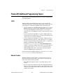
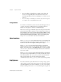
Channel API Additional Programming Topics..............................................................6-11
Get Names .......................................................................................................6-11
Synchronization...............................................................................................6-11
Set Property .....................................................................................................6-12
Frame to Channel Conversion .......................................................................................6-12
When Should I Use Frame to Channel Conversion?.......................................6-13
Logging .............................................................................................6-13
CompactRIO .....................................................................................6-14
Development without CAN Hardware..............................................6-15
Database Queries...............................................................................6-15
Enhance an Existing Frame API Application ...................................6-15
USB-847x..........................................................................................6-15
Virtual Bus Timing..........................................................................................6-16
Limitations.......................................................................................................6-17
Programming Model for Virtual Bus Timing Disabled ..................................6-21
Mode Dependent Channels ............................................................................................6-23
Mode Dependent Channels in MAX ...............................................................6-24
© National Instruments Corporation
ix
NI-CAN Hardware and Software Manual
Contents
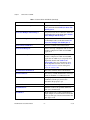
Chapter 7
Channel API for LabVIEW
Section Headings ........................................................................................................... 7-1
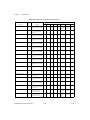
List of VIs...................................................................................................................... 7-1
CAN Clear.vi................................................................................................................. 7-4
CAN Clear with NI-DAQ.vi.......................................................................................... 7-6
CAN Clear with NI-DAQmx.vi .................................................................................... 7-8
CAN Clear Multiple with NI-DAQ.vi........................................................................... 7-10
CAN Clear Multiple with NI-DAQmx.vi...................................................................... 7-12
CAN Connect Terminals.vi ........................................................................................... 7-14
CAN Create Message.vi ................................................................................................ 7-24
CAN Create MessageEx.vi............................................................................................ 7-30
CAN Disconnect Terminals.vi ...................................................................................... 7-37
CAN Get Names.vi........................................................................................................ 7-39
CAN Get Property.vi ..................................................................................................... 7-42
CAN Initialize.vi ........................................................................................................... 7-55
CAN Init Start.vi ........................................................................................................... 7-59
CAN Read.vi ................................................................................................................. 7-65
CAN Set Property.vi...................................................................................................... 7-73
CAN Start.vi .................................................................................................................. 7-88
CAN Stop.vi .................................................................................................................. 7-90
CAN Sync Start with NI-DAQ.vi.................................................................................. 7-92
CAN Sync Start with NI-DAQmx.vi............................................................................. 7-94
CAN Sync Start Multiple with NI-DAQ.vi................................................................... 7-97
CAN Sync Start Multiple with NI-DAQmx.vi.............................................................. 7-100
CAN Write.vi ................................................................................................................ 7-103
Chapter 8
Channel API for C
Section Headings ........................................................................................................... 8-1
Data Types..................................................................................................................... 8-1
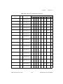
List of Functions............................................................................................................ 8-2
nctClear.......................................................................................................................... 8-4
nctConnectTerminals..................................................................................................... 8-5
nctCreateMessage.......................................................................................................... 8-15
nctCreateMessageEx ..................................................................................................... 8-20
nctDisconnectTerminals ................................................................................................ 8-26
nctGetNames ................................................................................................................. 8-28
nctGetNamesLength ...................................................................................................... 8-31
nctGetProperty............................................................................................................... 8-33
nctInitialize .................................................................................................................... 8-44
nctInitStart ..................................................................................................................... 8-47
NI-CAN Hardware and Software Manual
x
ni.com
Contents
nctRead ..........................................................................................................................8-53
nctReadTimestamped.....................................................................................................8-57
nctSetProperty................................................................................................................8-60
nctStart ...........................................................................................................................8-75
nctStop ...........................................................................................................................8-76
nctWrite .........................................................................................................................8-77
Chapter 9
Using the Frame API
Choose Which Objects To Use ......................................................................................9-1
Using CAN Network Interface Objects...........................................................9-1
Using LIN Network Interface Objects ............................................................9-2
Using CAN Objects.........................................................................................9-3
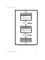
Frame API Basic Programming Model for CAN ..........................................................9-4
Frame API Basic Programming Model for LIN ............................................................9-7
LIN Interface as Bus Monitor..........................................................................9-7
LIN Interface as Master...................................................................................9-10
LIN Interface as Slave Device.........................................................................9-14
LIN Interface Accesses Single Subscribing Slave Device ..............................9-17
LIN Interface Accesses Single Publishing Slave Device ................................9-20
LIN Interface Sleep and Wakeup Behavior.....................................................9-23
Frame API Additional Programming Topics.................................................................9-25
RTSI ...............................................................................................................9-25
Remote Frames................................................................................................9-25
Using Queues...................................................................................................9-26
State Transitions ..............................................................................................9-26
Empty Queues .................................................................................................9-26
Full Queues......................................................................................................9-27
Disabling Queues.............................................................................................9-27
Using the CAN Network Interface Object with CAN Objects........................9-27
Detecting State Changes..................................................................................9-29
Frame to Channel Conversion .........................................................................9-29
Differences between CAN and LIN ................................................................9-30
Chapter 10
Frame API for LabVIEW
Section Headings ...........................................................................................................10-1
List of VIs ......................................................................................................................10-2
ncAction.vi.....................................................................................................................10-4
ncClose.vi ......................................................................................................................10-8
ncConfigCANNet.vi ......................................................................................................10-10
ncConfigCANNetRTSI.vi..............................................................................................10-15
© National Instruments Corporation
xi
NI-CAN Hardware and Software Manual
Contents
ncConfigCANObj.vi...................................................................................................... 10-19
ncConfigCANObjRTSI.vi ............................................................................................. 10-27
ncConnectTerminals.vi.................................................................................................. 10-32
ncDisconnectTerminals.vi ............................................................................................. 10-41
ncGetAttr.vi ................................................................................................................... 10-43
ncGetHardwareInfo.vi ................................................................................................... 10-58
ncGetTimer.vi................................................................................................................ 10-63
ncOpen.vi....................................................................................................................... 10-65
ncReadNet.vi ................................................................................................................. 10-68
ncReadNetMult.vi ......................................................................................................... 10-79
ncReadObj.vi ................................................................................................................. 10-90
ncReadObjMult.vi ......................................................................................................... 10-93
ncSetAttr.vi.................................................................................................................... 10-96
ncWaitForState.vi.......................................................................................................... 10-125
ncWriteNet.vi ................................................................................................................ 10-129
ncWriteNetMult.vi......................................................................................................... 10-137
ncWriteObj.vi ................................................................................................................ 10-149
Chapter 11
Frame API for C
Section Headings ........................................................................................................... 11-1
Data Types..................................................................................................................... 11-2
List of Functions............................................................................................................ 11-3
ncAction ........................................................................................................................ 11-5
ncCloseObject................................................................................................................ 11-8
ncConfig ........................................................................................................................ 11-9
ncConnectTerminals...................................................................................................... 11-29
ncCreateNotification...................................................................................................... 11-39
ncDisconnectTerminals ................................................................................................. 11-44
ncGetAttribute ............................................................................................................... 11-46
ncGetHardwareInfo ....................................................................................................... 11-61
ncOpenObject ................................................................................................................ 11-66
ncRead ........................................................................................................................... 11-68
ncReadMult ................................................................................................................... 11-81
ncSetAttribute................................................................................................................ 11-83
ncStatusToString ........................................................................................................... 11-112
ncWaitForState .............................................................................................................. 11-115
ncWrite .......................................................................................................................... 11-118
ncWriteMult .................................................................................................................. 11-126
NI-CAN Hardware and Software Manual
xii
ni.com
Contents
Appendix A
Troubleshooting and Common Questions
Troubleshooting with the Measurement & Automation Explorer (MAX) ....................A-1
Troubleshooting Self Test Failures................................................................................A-2
Common Questions........................................................................................................A-3
Appendix B
Summary of the CAN Standard
History and Use of CAN................................................................................................B-1
CAN Identifiers and Message Priority...........................................................................B-2
CAN Frames ..................................................................................................................B-3
CAN Error Detection and Confinement ........................................................................B-5
Low-Speed CAN............................................................................................................B-8
Appendix C
Summary of the LIN Standard
History and Use of LIN .................................................................................................C-1
LIN Frame Format .........................................................................................................C-1
LIN Bus Timing.............................................................................................................C-4
LIN Topology and Behavior..........................................................................................C-5
LIN Error Detection and Confinement ..........................................................................C-6
LIN Sleep and Wakeup..................................................................................................C-6
Advanced Frame Types .................................................................................................C-7
Additional LIN Information...........................................................................................C-8
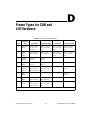
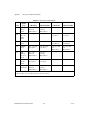
Appendix D
Frame Types for CAN and LIN Hardware
Appendix E
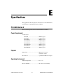
Specifications
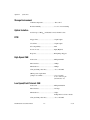
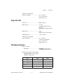
PCI-CAN Series 2..........................................................................................................E-1
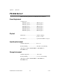
PXI-846x Series 2 ..........................................................................................................E-4
PCMCIA-CAN Series 2.................................................................................................E-7
USB-CAN and USB-LIN ..............................................................................................E-10
Safety .............................................................................................................................E-12
© National Instruments Corporation
xiii
NI-CAN Hardware and Software Manual
Contents
Appendix F
Technical Support and Professional Services
Glossary
Index
NI-CAN Hardware and Software Manual
xiv
ni.com
About This Manual
Use the NI-CAN Software and Hardware Installation Guide included with
your kit to install and configure the NI-CAN hardware and software. Use
this manual to learn the basics of NI-CAN, as well as how to develop an
application.
This manual contains specific programmer reference information about
each NI-CAN function and VI.
This manual also describes the hardware features. Unless otherwise noted,
this manual applies to the NI CAN Series 2 products, which include the
following.
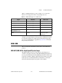
PCI-CAN
•
PCI-CAN Series 2 (High-Speed; 1 port)
•
PCI-CAN/2 Series 2 (High-Speed; 2 ports)
•
PCI-CAN/LS Series 2 (Low-Speed/Fault-Tolerant; 1 port)
•
PCI-CAN/LS2 Series 2 (Low-Speed/Fault-Tolerant; 2 ports)
•
PCI-CAN/XS Series 2 (Software Selectable; 1 port)
•
PCI-CAN/XS2 Series 2 (Software Selectable; 2 ports)
•
PXI-8461 Series 2 (High-Speed; 1 or 2 ports)
•
PXI-8460 Series 2 (Low-Speed/Fault-Tolerant; 1 or 2 ports)
•
PXI-8464 Series 2 (Software Selectable; 1 or 2 ports)
•
PCMCIA-CAN Series 2 (High-Speed; 1 port)
•
PCMCIA-CAN/2 Series 2 (High-Speed; 2 ports)
•
PCMCIA-CAN/LS Series 2 (Low-Speed/Fault-Tolerant; 1 port)
•
PCMCIA-CAN/LS2 Series 2 (Low-Speed/Fault-Tolerant; 2 port)
•
PCMCIA-CAN/SW Series 2 (Single Wire; 1 port)
PXI-846x
PCMCIA-CAN
© National Instruments Corporation
xv
NI-CAN Hardware and Software Manual
About This Manual
•
PCMCIA-CAN/HS/LS Series 2 (1 port High-Speed,
1 port Low-Speed/Fault-Tolerant)
•
PCMCIA-CAN/HS/SW Series 2 (1 port High-Speed,
1 port Single Wire)
•
USB-8473 (High-Speed CAN; 1 port)
•
USB-8473s (High-Speed CAN; 1 port, with Synchronization)
•
USB-8472 (Low-Speed CAN; 1 port)
•
USB-8472s (Low-Speed CAN; 1 port, with Synchronization)
•
USB-8476 (LIN; 1 port)
•
USB-8476s (LIN; 1 port, with Synchronization)
USB-CAN
USB-LIN
NI-CAN hardware products that pre-date the Series 2 product line are now
referred to as Series 1. NI CAN Series 2 products contain several
enhancements over Series 1 products, including the Philips SJA1000 CAN
controller, improved RTSI synchronization features, updated CAN
transceivers, and XS Software Selectable hardware for PCI and PXI.
NI-CAN software continues to fully support Series 1 hardware. However,
some advanced features are available only with Series 2 hardware. For
instance, with PCMCIA, both the card and the cable must be Series 2 to use
the advanced features. For a complete description of the differences
between Series 1 and Series 2 NI CAN hardware, refer to the Series 2 Vs.
Series 1 section of Chapter 1, Introduction.
To obtain complete documentation of NI CAN Series 1 hardware, refer to
the previous version of the NI-CAN Hardware and Software Manual,
part number 370289x-01, where x is the letter preceding the one used
in this manual. The previous version of this manual is available at
ni.com/manuals.
NI-CAN Hardware and Software Manual
xvi
ni.com
About This Manual
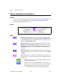
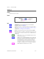
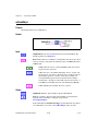
Conventions Used in This Manual
The following conventions appear in this manual:
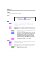
»
The » symbol leads you through nested menu items and dialog box options
to a final action. The sequence File»Page Setup»Options directs you to
pull down the File menu, select the Page Setup item, and select Options
from the last dialog box.
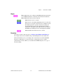
This icon denotes a note, which alerts you to important information.
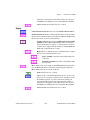
bold
Bold text denotes items that you must select or click in the software, such
as menu items and dialog box options. Bold text also denotes parameter
names.
italic
Italic text denotes variables, emphasis, a cross-reference, or an introduction
to a key concept. Italic text also denotes text that is a placeholder for a word
or value that you must supply.
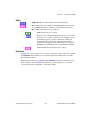
monospace
Text in this font denotes text or characters that you should enter from the
keyboard, sections of code, programming examples, and syntax examples.
This font is also used for the proper names of disk drives, paths, directories,
programs, subprograms, subroutines, device names, functions, operations,
variables, filenames, and extensions.
monospace bold
Bold text in this font denotes the messages and responses that the computer
automatically prints to the screen. This font also emphasizes lines of code
that are different from the other examples.
monospace italic
Italic text in this font denotes text that is a placeholder for a word or value
that you must supply.
Related Documentation
The following documents contain information that you might find helpful
as you read this manual:
•
ANSI/ISO Standard 11898-1993, Road Vehicles—Interchange of
Digital Information—Controller Area Network (CAN) for High-Speed
Communication
•
ANSI/ISO Standard 11519-1, 2 Road Vehicles—Low Speed Serial
Data Communications, Part 1 and 2
© National Instruments Corporation
xvii
NI-CAN Hardware and Software Manual
About This Manual
•
CAN Specification Version 2.0, 1991, Robert Bosch GmbH., Postfach
106050, D-70049 Stuttgart 1
•
CiA Draft Standard 102, Version 2.0, CAN Physical Layer for
Industrial Applications
•
CompactPCI Specification, Revision 2.0, PCI Industrial Computers
Manufacturers Group
•
DeviceNet Specification, Version 2.0, Open DeviceNet Vendor
Association
•
PXI Hardware Specification, Revision 2.1, National Instruments
Corporation
•
PXI Software Specification, Revision 2.1, National Instruments
Corporation
•
LabVIEW Online Reference
•
Measurement and Automation Explorer (MAX) Online Reference
•
Microsoft Win32 Software Development Kit (SDK) Online Help
•
SAE J2411, Single Wire CAN Recommended Practices
NI-CAN Hardware and Software Manual
xviii
ni.com
1
Introduction
This chapter provides an introduction to the Controller Area Network
(CAN), the Local Interconnect Network (LIN), and the National
Instruments products for CAN and LIN.
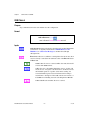
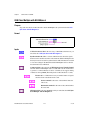
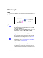
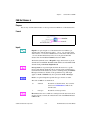
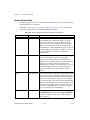
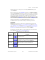
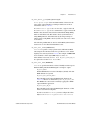
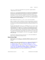
CAN Overview
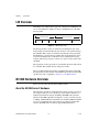
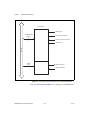
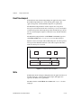
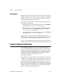
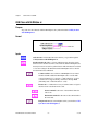
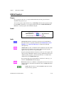
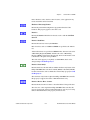
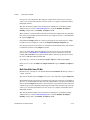
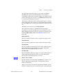
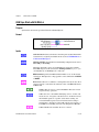
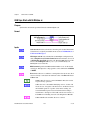
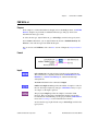
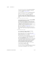
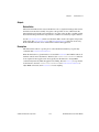
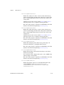
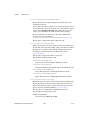
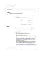
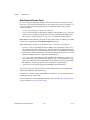
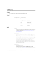
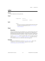
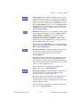
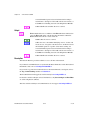
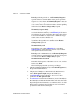
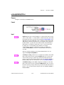
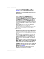
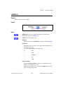
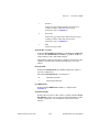
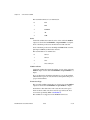
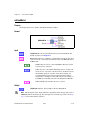
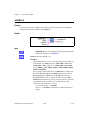
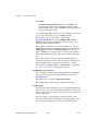
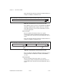
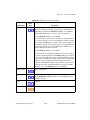
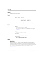
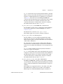
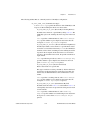
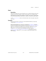
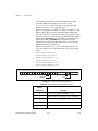
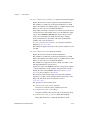
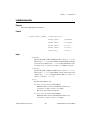
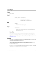
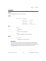
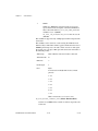
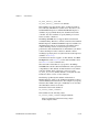
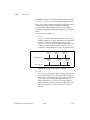
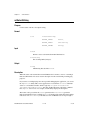
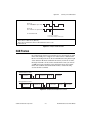
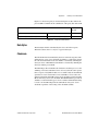
The data frame is the fundamental unit of data transfer on a CAN network.
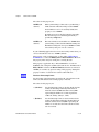
Figure 1-1 shows a simplified view of the CAN data frame.
Identifier
Length
Data
Figure 1-1. CAN Data Frame
Simplified CAN Data Frame
When multiple CAN devices transmit a frame at the same time, the
identifier (ID) resolves the collision. The highest priority ID continues, and
the lower priority IDs retry immediately afterward. The ISO 11898 CAN
standard specifies two ID formats: the standard format of 11 bits and the
extended format of 29 bits.
The ID is followed by a length code that specifies the number of data bytes
in the frame. The length ranges from 0 to 8 data bytes. The ID value
determines the meaning of the data bytes.
In addition to the data frame, the CAN standard specifies the remote frame.
The remote frame includes the ID, but no data bytes. A CAN device
transmits the remote frame to request that another device transmit the
associated data frame for the ID. In other words, the remote frame provides
a mechanism to poll for data.
The preceding information provides a simplified description of CAN
frames. The CAN frame format includes many other fields, such as for error
checking and acknowledgement. For more detailed information on the ISO
11898 CAN standard, refer to Appendix B, Summary of the CAN Standard.
© National Instruments Corporation
1-1
NI-CAN Hardware and Software Manual
Chapter 1
Introduction
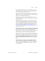
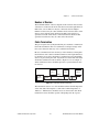
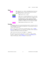
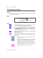
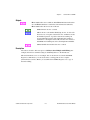
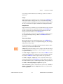
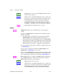
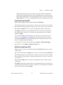
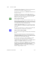
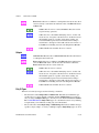
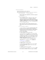
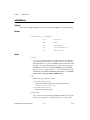
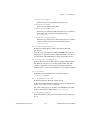
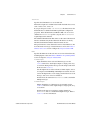
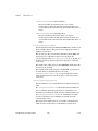
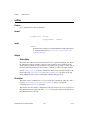
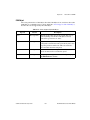
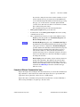
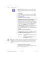
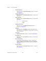
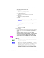
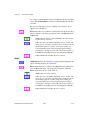
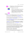
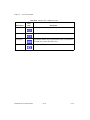
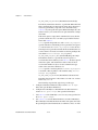
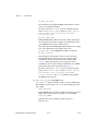
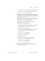
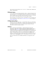
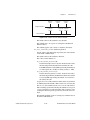
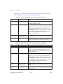
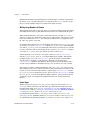
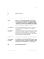
LIN Overview
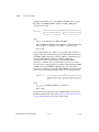
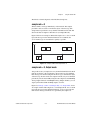
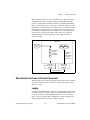
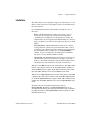
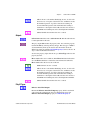
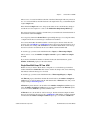
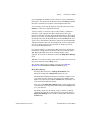
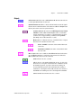
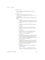
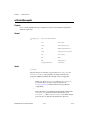
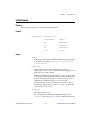
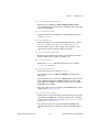
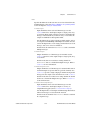
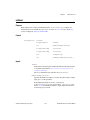
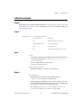
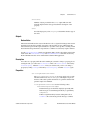
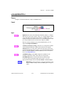
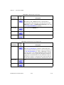
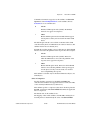
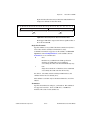
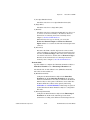
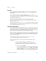
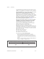
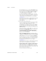
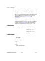
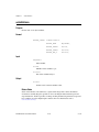
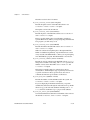
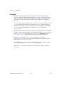
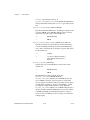
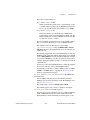
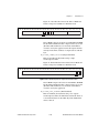
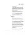
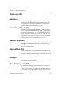
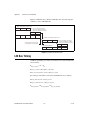
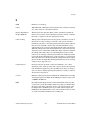
The LIN bus uses a Master/Slave approach, comprised of a LIN Master and
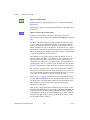
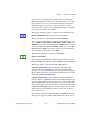
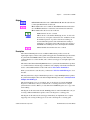
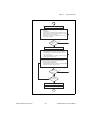
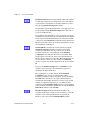
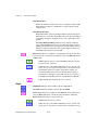
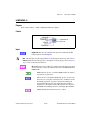
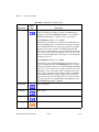
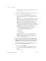
one or more LIN Slaves. Figure 1-2 shows a simplified view of the LIN
message frame.
Message Response
Message Header
Break
Sync
Identifier
Data
Checksum
Figure 1-2. LIN Message Frame
The message header consists of a break used to identify the start of the
frame and the sync field used by the slave node for clock synchronization.
The identifier (ID) consists of a 6-bit message ID and a 2-bit parity field.
The ID denotes a specific message address, but not the destination. Upon
reception and interpretation of the ID one slave will begin the message
response. The message response consists of 1–8 bytes of data and an 8-bit
checksum.
The sequencing of message frames is controlled by the master and is fixed
in a schedule. The schedule may be changed as needed.
The proceeding information provides a simplified description of the LIN
message frame. For more details on the LIN message frame and on the LIN
specification, refer to Appendix C, Summary of the LIN Standard.
NI CAN Hardware Overview
This section describes the NI CAN and LIN hardware.
About the NI CAN Series 2 Hardware
NI CAN Series 2 hardware and the NI-CAN software package provide an
easy and powerful way to use a desktop or notebook PC to interface to a
CAN bus. The hardware features the Philips SJA1000 CAN controller,
which is CAN 2.0B compatible and supports a variety of transfer rates up
to 1 Mbps. All NI CAN Series 2 hardware uses the Intel 386EX embedded
processor to implement time-critical features provided by the NI-CAN
software. NI CAN Series 2 hardware supports High-Speed and
NI-CAN Hardware and Software Manual
1-2
ni.com
Chapter 1
Introduction
Low-Speed/Fault-Tolerant physical layers, which fully conform to the
ISO 11898 physical layer specification for CAN. In addition, NI CAN
Series 2 hardware supports Single Wire CAN.
PCI-CAN Series 2 hardware supports the Real-Time System Integration
(RTSI) bus as a way to synchronize multiple interface cards in a system by
sharing common timing and triggering signals.
PXI-846x Series 2 hardware supports the PXI trigger bus as a way to
synchronize multiple interface cards in a system by sharing common timing
and triggering signals.
PCMCIA-CAN Series 2 cards provide a way to synchronize multiple
devices by using the PCMCIA-CAN Synchronization cable to externally
connect to shared timing and triggering signals. For more information
about the synchronization capabilities of the NI CAN Series 2 hardware,
refer to the RTSI section, the PXI Trigger Bus (RTSI) section, or the
Synchronization section of Chapter 3, NI CAN and LIN Hardware, for the
appropriate hardware type.
PCI-CAN Series 2 hardware is software configurable and compliant with
the PCI Local Bus Specification. It features the National Instruments MITE
bus interface chip that connects the card to the PCI I/O bus. With a
PCI-CAN Series 2 card, you can make the PC-compatible computer with
PCI Local Bus slots communicate with and control CAN devices.
PXI-846x Series 2 hardware is software configurable and compliant with
the PXI Specification and the CompactPCI Specification. It features the
National Instruments MITE bus interface chip that connects the card to the
PXI or CompactPCI I/O bus. With a PXI-846x Series 2 card, you can make
the PXI or CompactPCI chassis communicate with and control CAN
devices.
PCMCIA-CAN Series 2 hardware is a 16-bit, Type II PC Card that is
software configurable and compliant with the PCMCIA standards for
16-bit PC Cards. With a PCMCIA-CAN Series 2 card, you can make the
PC-compatible notebook with PCMCIA slots communicate with and
control CAN devices.
© National Instruments Corporation
1-3
NI-CAN Hardware and Software Manual
Chapter 1
Introduction
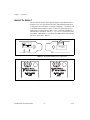
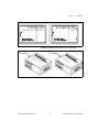
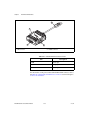
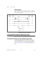
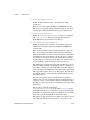
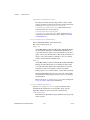
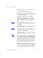
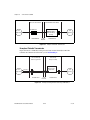
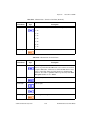
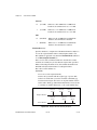
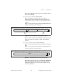
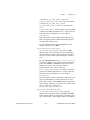
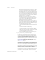
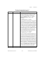
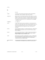
Series 2 Vs. Series 1
The technical information in this help file applies to the NI CAN Series 2
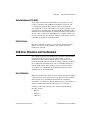
hardware. You can easily identify the series of the NI CAN hardware by
looking at the label. Use Figure 1-3, Figure 1-4, Figure 1-5, and Figure 1-6
to determine if the hardware is Series 1 or Series 2. If the label does not
indicate Series 2, the hardware is Series 1. For complete documentation of
NI CAN Series 1 hardware, refer to ni.com/manuals and search for the
part number 370289E-01 to access the October 2002 edition of the NI-CAN
Hardware and Software Manual.
®
NI PCI-CAN
Series 2
Figure 1-3. NI PCI-CAN Hardware Series 1 and 2 Labels
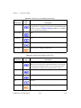
Series 2
Figure 1-4. NI PXI-CAN Hardware Series 1 and 2 Labels
NI-CAN Hardware and Software Manual
1-4
ni.com
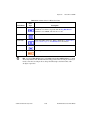
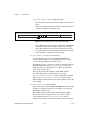
Chapter 1
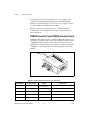
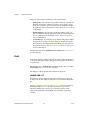
PCMCIA-CAN
NI PCMCIA-CAN
with high & low speed CAN support
Series 2
Introduction
Figure 1-5. NI PCMCIA-CAN Hardware Series 1 and 2 Labels
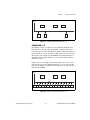
CA
C
N
A
VL
C_ H
S H
C_ V+
er
nt
(I
V-
,
r)
w
lP
na
T
R
J2
O
P
J2
1
J1
N/
HS
S
L erie
s2
,P
SH
H or t 1
C_
V+
C_
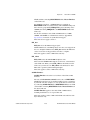
J1
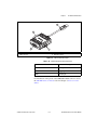
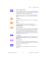
Figure 1-6. NI PCMCIA-CAN Series 1 and 2 Cables
© National Instruments Corporation
1-5
NI-CAN Hardware and Software Manual
Chapter 1
Introduction
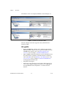
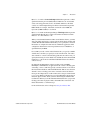
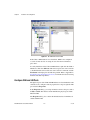
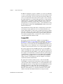
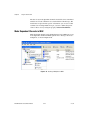
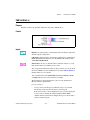
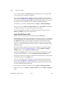
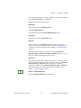
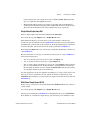
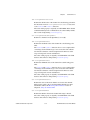
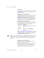
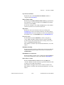
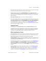
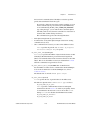
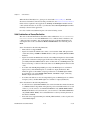
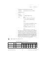
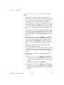
The hardware series is also displayed in MAX, as shown in Figure 1-7.
Figure 1-7. Hardware Series Displayed in MAX
The new and improved features supported only by NI CAN Series 2
hardware include:
PCI and PXI
•
Philips SJA1000 CAN controller. Series 1 hardware supported the
Intel 82527 CAN controller. For more specific information about the
SJA1000 CAN controller, refer to the Philips SJA1000 CAN
Controller section of Chapter 3, NI CAN and LIN Hardware.
•
Improved RTSI synchronization features. For more information about
the synchronization capabilities of the NI CAN Series 2 hardware,
refer to the RTSI section, the PXI Trigger Bus (RTSI) section, or the
Synchronization section of Chapter 3, NI CAN and LIN Hardware,
for the appropriate hardware type.
•
Single Wire CAN support.
•
XS Software selectable physical layer hardware. This feature allows
you to easily configure a CAN port in software to be a High-Speed,
Low-Speed/Fault-Tolerant, Single Wire, or external transceiver
interface.
NI-CAN Hardware and Software Manual
1-6
ni.com
Chapter 1
Introduction
•
Upgraded CAN transceivers. High-speed hardware uses the Philips
TJA1041 transceiver; Low-Speed/Fault-Tolerant hardware uses the
Philips TJA1054A transceiver. Both transceivers have increased
voltage tolerance and improved EMC performance over their NI CAN
Series 1 predecessors.
•
Internally powered physical layer with independent jumper option for
controlling the VBAT transceiver input pin either internally or
externally. This means High-Speed and Low-Speed/Fault-Tolerant
hardware is fully functional by default without supplying any bus
power. A jumper option exists to select the source for the VBAT
transceiver pin between internal (default) or external. Note that Single
Wire CAN requires external bus power.
PCMCIA
•
Philips SJA1000 CAN controller. Series 1 hardware supported the
Intel 82527 CAN controller. For more specific information about the
SJA1000 CAN controller, refer to the Philips SJA1000 CAN
Controller section of Chapter 3, NI CAN and LIN Hardware.
•
Synchronization capability for PCMCIA hardware. For more
information about PCMCIA synchronization, refer to the
Synchronization section of Chapter 3, NI CAN and LIN Hardware.
•
Improved performance and reduced power consumption. For more
information, refer to Appendix C, Summary of the LIN Standard.
PCMCIA Cables
•
Single Wire CAN support.
•
Upgraded CAN transceivers. High-speed hardware uses the Philips
TJA1041 transceiver; Low-Speed/Fault-Tolerant hardware uses the
Philips TJA1054A transceiver. Both transceivers have increased
voltage tolerance and improved EMC performance over their NI CAN
Series 1 predecessors.
•
Internally powered physical layer for High-Speed and
Low-Speed/Fault Tolerant. This means High-Speed and
Low-Speed/Fault-Tolerant hardware is fully functional by default
without supplying any bus power. Note that Single Wire CAN requires
external bus power.
•
NI-CAN 2.2 is required for full functionality of the PCMCIA cables.
Using these cables with any version of NI-CAN prior to 2.2 will
prevent use of the following functions:
© National Instruments Corporation
1-7
NI-CAN Hardware and Software Manual
Chapter 1
Introduction
•
High-speed error reporting
•
Transceiver sleep modes
•
Single-wire transceivers
About the USB-847x Hardware
NI USB-847x hardware provides a powerful and flexible way to interface
any desktop or notebook PC to a CAN or LIN bus via USB. All CAN
hardware features the Philips SJA1000 CAN controller, which is
CAN 2.0B compatible and supports a variety of transfer rates up to 1 Mbps.
The SJA1000 also includes a number of features well-suited to diagnostic
applications. USB-847x hardware supports High-Speed and
Low-Speed/Fault-Tolerant physical layers, which fully conform to the
ISO 11898 specification for CAN. All LIN devices are LIN 1.3, LIN 2.0
and SAE J2602 compliant and support the full range of LIN baud rates.
NI USB-847x with Sync series hardware is based on a powerful USB 2.0
compatible microcontroller capable of host data transfer rates up to
480 Mbps. The hardware includes onboard buffers to prevent dropped
frames at high CAN data rates. All USB-847x CAN devices are fully
powered from the USB and require no external power supply.
Additionally, USB-847x with Sync series hardware provides a way to
synchronize multiple devices by using an external sync connector to share
common timing and triggering signals. USB-847x with Sync series
hardware can share a timebase with each other or with a variety of data
acquisition products.
CAN: USB-8472, USB-8472s, USB-8473, USB-8473s
•
Philips SJA1000 CAN controller. For more specific information about
the SJA1000 CAN controller, refer to the Philips SJA1000 CAN
Controller section of Chapter 3, NI CAN and LIN Hardware.
•
Synchronization via RTSI or any 1/10/20 MHz timebase source. For
more information refer to the ncConnectTerminals function within
the Frame API.
•
High-Speed hardware uses the Philips TJA1041 transceiver;
Low-Speed/Fault-Tolerant hardware uses the Philips TJA1054A
transceiver. Both transceivers have increased voltage tolerance and
improved EMC performance over NI CAN Series 1 hardware.
•
Low-Speed/Fault-Tolerant CAN support with software selectable bus
termination.
NI-CAN Hardware and Software Manual
1-8
ni.com
Chapter 1
Introduction
•
High performance USB 2.0 connection with data transfer rates up to
480 Mbps.
•
Fully powered by the USB. No bus power needed.
LIN: USB-8476, USB-8476s
•
Synchronization via RTSI or any 1/10/20 MHz timebase source. For
more information refer to the ncConnectTerminals functions within
the Frame API.
•
Software selectable master/slave termination.
•
Atmel ATA6620 LIN transceiver with –27V to 60V LIN bus voltage
tolerance.
•
High performance USB 2.0 connection with data transfer rates up to
480 Mbps.
•
Hardware VBat detection.
NI-CAN Software Overview
The NI-CAN software provides full-featured Application Programming
Interfaces (APIs), plus tools for configuration and analysis within National
Instruments Measurement & Automation Explorer (MAX). The NI-CAN
APIs enable you to develop applications that are customized to the test and
simulation requirements.
MAX
The NI-CAN features within MAX enable you to:
•
Verify the installation of the NI CAN hardware.
•
Configure software properties for each CAN port.
•
Create or import configuration information for the Channel API.
•
Interact with the CAN network using various tools.
For more information, refer to Chapter 2, Installation and Configuration.
© National Instruments Corporation
1-9
NI-CAN Hardware and Software Manual
Chapter 1
Introduction
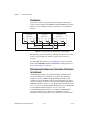
Frame API
As described in the CAN Overview section, the frame is the fundamental
unit of data transfer on a CAN network. The NI-CAN Frame API provides
a set of functions to write and read CAN frames.
Within the Frame API, the data bytes of each frame are not interpreted, but
are transferred in their raw format. For example, you can transmit a data
frame by calling a write function with the ID, length, and array of data
bytes.
For more information, refer to Chapter 9, Using the Frame API.
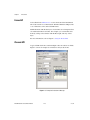
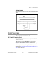
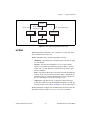
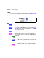
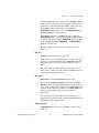
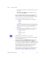
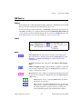
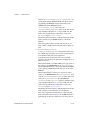
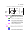
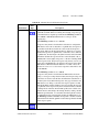
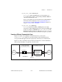
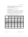
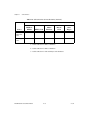
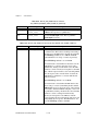
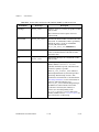
Channel API
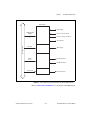
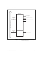
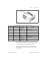
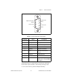
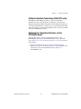
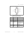
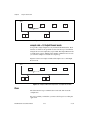
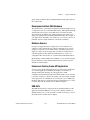
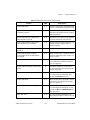
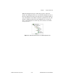
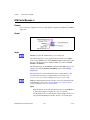
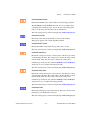
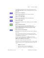
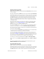
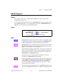
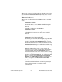
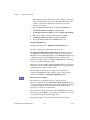
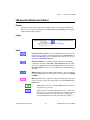
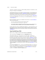
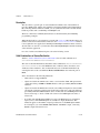
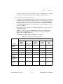
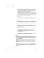
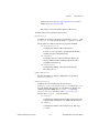
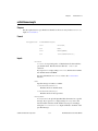
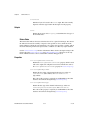
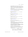
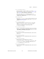
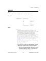
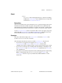
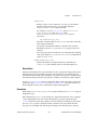
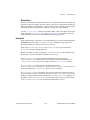
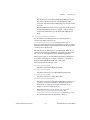
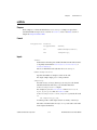
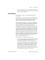
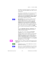
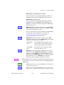
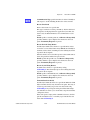
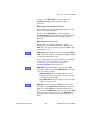
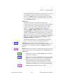
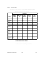
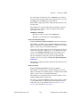
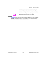
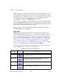
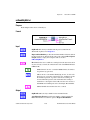
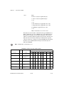
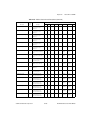
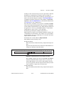
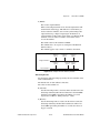
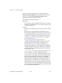
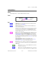
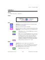
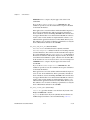
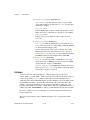
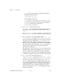
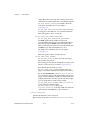
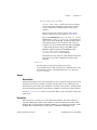
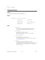
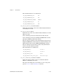
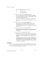
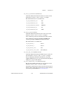
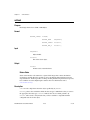
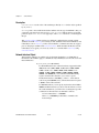
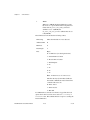
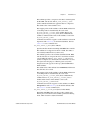
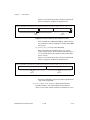
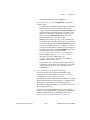
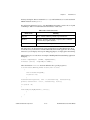
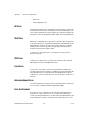
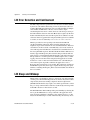
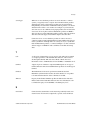
A typical CAN data frame contains multiple values encoded as raw fields.
Figure 1-8 shows an example set of fields for a 6-byte data frame.
Figure 1-8. Example of CruiseControl Message
NI-CAN Hardware and Software Manual
1-10
ni.com
Chapter 1
Introduction
Bytes 1 to 2 contain a CruiseCtrlSetSpeed field that represents a vehicle
speed in kilometers per hour (km/h). Most CAN devices do not transmit
values as floating-point units such as 115.6 km/h. Therefore, this field
consists of a 16-bit unsigned integer in which each increment represents
0.0039 km/h. For example, if the field contains the value 25000, that
represents (25000 * 0.0039) = 97.5 km/h.
Bytes 3 to 4 contain another unsigned integer VehicleSpeed that represents
speed in km/h. Bytes 0 and 5 contain various Boolean fields for which 1
indicates “on” and 0 indicates “off.”
When you use the NI-CAN Frame API to read CAN data frames, you must
write code in the application to convert each raw field to physical units such
as km/h. The NI-CAN Channel API enables you to specify this conversion
information at configuration time instead of within the application. This
configuration information can be imported from Vector CANdb files, or
specified directly in MAX.
For each ID you read or write on the CAN network, you specify a number
of fields. For each field, you specify its location in the frame, size in bits,
and a formula to convert to/from floating-point units. In other words, you
specify the meaning of various fields in each CAN data frame. In NI-CAN
terminology, a data frame for which the individual fields are described is
called a message.
In other National Instruments software products such as NI-DAQ,
NI-DAQmx, and FieldPoint, an application reads or writes a floating-point
value using a channel, which is typically converted to/from a raw value in
the measurement hardware. The NI-CAN Channel API also uses the term
channel to refer to floating-point values converted to/from raw fields in
messages. In CAN products of other vendors, this concept is often referred
to as a signal. When a CAN message is received, NI-CAN converts the raw
fields into physical units, which you then obtain using the Channel API
read function. When you call the Channel API write function, you provide
floating-point values in physical units, which NI-CAN converts into raw
fields and transmits as a CAN message.
For more information, refer to Chapter 6, Using the Channel API.
© National Instruments Corporation
1-11
NI-CAN Hardware and Software Manual
Installation and Configuration
2
This chapter explains how to install and configure CAN hardware.
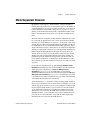
Safety Information
The following section contains important safety information that you must
follow when installing and using the module.
Do not operate the module in a manner not specified in this document.
Misuse of the module can result in a hazard. You can compromise the safety
protection built into the module if the module is damaged in any way. If the
module is damaged, return it to National Instruments (NI) for repair.
Do not substitute parts or modify the module except as described in this
document. Use the module only with the chassis, modules, accessories, and
cables specified in the installation instructions. You must have all covers
and filler panels installed during operation of the module.
Do not operate the module in an explosive atmosphere or where there may
be flammable gases or fumes. If you must operate the module in such an
environment, it must be in a suitably rated enclosure.
If you need to clean the module, use a soft, nonmetallic brush. Make sure
that the module is completely dry and free from contaminants before
returning it to service.
Operate the module only at or below Pollution Degree 2. Pollution is
foreign matter in a solid, liquid, or gaseous state that can reduce dielectric
strength or surface resistivity. The following is a description of pollution
degrees:
Pollution Degree 1 means no pollution or only dry, nonconductive pollution
occurs. The pollution has no influence.
Pollution Degree 2 means that only nonconductive pollution occurs in most
cases. Occasionally, however, a temporary conductivity caused by
condensation must be expected.
© National Instruments Corporation
2-1
NI-CAN Hardware and Software Manual
Chapter 2
Installation and Configuration
Pollution Degree 3 means that conductive pollution occurs, or dry,
nonconductive pollution occurs that becomes conductive due to
condensation.
You must insulate signal connections for the maximum voltage for which
the module is rated. Do not exceed the maximum ratings for the module.
Do not install wiring while the module is live with electrical signals.
Do not remove or add connector blocks when power is connected to the
system. Avoid contact between your body and the connector block signal
when hot swapping modules. Remove power from signal lines before
connecting them to or disconnecting them from the module.
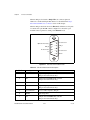
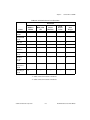
Operate the module at or below the installation category1 marked on the
hardware label. Measurement circuits are subjected to working voltages2
and transient stresses (overvoltage) from the circuit to which they are
connected during measurement or test. Installation categories establish
standard impulse withstand voltage levels that commonly occur in
electrical distribution systems. The following is a description of installation
categories:
1
2
3
•
Installation Category I is for measurements performed on circuits not
directly connected to the electrical distribution system referred to as
MAINS3 voltage. This category is for measurements of voltages from
specially protected secondary circuits. Such voltage measurements
include signal levels, special equipment, limited-energy parts of
equipment, circuits powered by regulated low-voltage sources, and
electronics.
•
Installation Category II is for measurements performed on circuits
directly connected to the electrical distribution system. This category
refers to local-level electrical distribution, such as that provided by a
standard wall outlet (for example, 115 AC voltage for U.S. or 230 AC
voltage for Europe). Examples of Installation Category II are
measurements performed on household appliances, portable tools, and
similar modules.
•
Installation Category III is for measurements performed in the building
installation at the distribution level. This category refers to
measurements on hard-wired equipment such as equipment in fixed
installations, distribution boards, and circuit breakers. Other examples
Installation categories, also referred to as measurement categories, are defined in electrical safety standard IEC 61010-1.
Working voltage is the highest rms value of an AC or DC voltage that can occur across any particular insulation.
MAINS is defined as a hazardous live electrical supply system that powers equipment. Suitably rated measuring circuits may
be connected to the MAINS for measuring purposes.
NI-CAN Hardware and Software Manual
2-2
ni.com
Chapter 2
Installation and Configuration
are wiring, including cables, bus bars, junction boxes, switches, socket
outlets in the fixed installation, and stationary motors with permanent
connections to fixed installations.
•
Installation Category IV is for measurements performed at the primary
electrical supply installation (<1,000 V). Examples include electricity
meters and measurements on primary overcurrent protection devices
and on ripple control units.
Measurement & Automation Explorer (MAX)
Measurement & Automation Explorer (MAX) provides access to all of the
National Instruments products. Like other NI software products, NI-CAN
uses MAX as the centralized location for all configuration and tools.
To launch MAX, select the Measurement & Automation shortcut on
the desktop, or within the Windows Programs menu under National
Instruments»Measurement & Automation.
For information on the NI-CAN software within MAX, consult the online
help within MAX.
A reference is located in the MAX Help menu under Help Topics»
NI-CAN.
View help for items in the MAX Configuration tree by using the built-in
MAX help pane. If this help pane is not shown on the far right, select the
Show/Hide button in the upper right.
View help for a dialog box by selecting the Help button in the window.
Verify Installation of CAN and LIN Hardware
Within the Devices & Interfaces branch of the MAX Configuration tree,
NI CAN and LIN hardware is listed along with other hardware in the local
computer system, as shown in Figure 2-1.
© National Instruments Corporation
2-3
NI-CAN Hardware and Software Manual
Chapter 2
Installation and Configuration
Figure 2-1. NI-CAN Cards Listed in MAX
If the CAN or LIN hardware is not listed here, MAX is not configured
to search for new devices on startup. To search for the new hardware,
press <F5>.
To verify installation of the CAN or LIN hardware, right-click the CAN or
LIN device, then select Self-test. If the self-test passes, the card icon shows
a checkmark. If the self-test fails, the card icon shows an X mark, and the
Test Status in the right pane describes the problem. Refer to Appendix A,
Troubleshooting and Common Questions, for information about resolving
hardware installation problems.
Configure CAN and LIN Ports
The physical ports of the CAN and LIN hardware are listed under the name
of the device. To configure software properties for each port, right-click the
port and select Properties.
In the Properties dialog, you assign an interface name to the port, such as
CAN0 or CAN1. The interface name identifies the physical port within
NI-CAN APIs.
The Properties dialog also contains the default baud rate for MAX tools
and the Channel API.
NI-CAN Hardware and Software Manual
2-4
ni.com
Chapter 2
Installation and Configuration
CAN Channels
Within the Data Neighborhood branch of the MAX Configuration tree,
the CAN Channels branch lists information for the NI-CAN Channel API,
as shown in Figure 2-2.
Figure 2-2. CAN Channels in MAX
The CAN Channels branch lists CAN messages for use with the Channel
API. A set of channels is specified for each message.
For information about creating information under CAN Channels, refer to
the Choose Source of Channel Configuration section of Chapter 6, Using
the Channel API.
© National Instruments Corporation
2-5
NI-CAN Hardware and Software Manual
Chapter 2
Installation and Configuration
LabVIEW Real-Time (RT) Configuration
LabVIEW Real-Time (RT) combines easy-to-use LabVIEW programming
with the power of real-time systems. When you use a National Instruments
PXI Controller you can install a PXI-CAN card and use the NI-CAN API
to develop real-time applications. For example, you can simulate the
behavior of a control algorithm within a CAN device, using data from
received CAN messages to generate outgoing CAN messages with
deterministic response times. This and other real-time applications can also
be developed if you are using CompactRIO as your LabVIEW RT system.
You can install a CompactRIO CAN module and use the NI-CAN software
and the LabVIEW FPGA I/O to develop your applications.
When you install the NI-CAN software, the installer checks for the
presence of the LabVIEW RT module. If LabVIEW RT exists, the NI-CAN
installer copies components for LabVIEW RT to the Windows system.
As with any other NI product for LabVIEW RT, you then download the
NI-CAN software to the LabVIEW RT system using the Remote Systems
branch in MAX. For more information, refer to the LabVIEW RT
documentation.
USB-847x hardware is not supported under LabVIEW RT.
PXI System
After you have installed the PXI CAN cards and downloaded the NI-CAN
software to the LabVIEW RT system, you need to verify the installation.
Within the Tools menu in MAX, select NI-CAN»RT Hardware
Configuration. The RT Hardware Configuration tool provides features
similar to Devices & Interfaces on the local system. Use the RT Hardware
Configuration tool to self-test the CAN cards and assign an interface name
to each physical CAN port.
To use the Channel API on the LabVIEW RT system, you must also
download channel configuration information. Right-click the CAN
Channels heading, then select Send to RT System. This downloads all
information under CAN Channels to the LabVIEW RT system, so you can
execute the same LabVIEW VIs on the LabVIEW RT system as on the
Windows system.
NI-CAN Hardware and Software Manual
2-6
ni.com
Chapter 2
Installation and Configuration
CompactRIO System
After you have installed the CompactRIO CAN modules and downloaded
NI-RIO and NI-CAN software, you need to enable the CompactRIO
Reconfigurable Embedded Chassis for use in LabVIEW. For instructions
on how to enable the CompactRIO Reconfigurable Embedded Chassis for
use in LabVIEW, refer to the MAX help.
To use the Channel API on the LabVIEW RT system, you must download
the channel configuration information. Right-click the CAN Channels
heading, then select Send to RT System. This downloads all the
information under CAN Channels to the LabVIEW RT system. To utilize
the CAN channels on the CompactRIO system, you need to use Frame to
Channel Conversion. For more information, refer to the Frame to Channel
Conversion section of Chapter 6, Using the Channel API.
Tools
NI-CAN provides tools that you can launch from MAX.
•
Bus Monitor—Displays statistics for CAN or LIN frames. This
provides a basic tool to analyze CAN or LIN network traffic. Launch
this tool by right-clicking a CAN or LIN interface (port).
•
Test Panel—Read or write physical units for a CAN channel. This
provides a simple debugging tool to experiment with CAN channels.
Launch this tool by right-clicking a CAN channel.
•
NI-Spy—Monitor function calls to the NI-CAN APIs. This tool helps
in debugging programming problems in the application. To launch this
tool, open the Software branch of the MAX Configuration tree,
right-click NI Spy, and select Launch NI Spy.
•
FP1300 Configuration—FieldPoint 1300 is the National Instruments
modular I/O product for CAN. If you have installed the software for
the FP1300 product, launch this tool by right-clicking a CAN interface
(port).
© National Instruments Corporation
2-7
NI-CAN Hardware and Software Manual
Chapter 2
Installation and Configuration
Using NI-CAN with NI-DNET
DeviceNet is a higher-level protocol based on CAN, typically used for
industrial automation or machine control applications. NI-DNET is the
National Instruments software for DeviceNet.
NI-CAN uses the same software infrastructure as NI-DNET, so both APIs
can be used with the same CAN card. The general rule is that each CAN
card can only be used for one API at a time.
Use of NI-DNET is restricted to port 1 (top port) of Series 1 CAN cards.
National Instruments hardware kits for CAN ship with Series 2 cards,
which cannot be used with NI-DNET. National Instruments hardware kits
for DeviceNet ship with Series 1 cards, which can be used with both
NI-DNET and NI-CAN. For information on identification of the series,
refer to the NI CAN Hardware Overview section of Chapter 1,
Introduction.
You can view each Series 1 CAN card in MAX with either DeviceNet or
CAN features. To change the view of a CAN card in MAX, right-click the
card and select Protocol. In this dialog you can select either DeviceNet for
NI-DNET, or CAN for NI-CAN. When the CAN protocol is selected, you
can access CAN tools in MAX, such as the Bus Monitor tool.
In order to develop NI-DNET applications, you must install NI-DNET
components such as documentation and examples. The NI-DNET software
components are available within the NI-CAN installer.
Launch the setup.exe program for the NI-CAN installer in the same
manner as the original installation (CD or ni.com download). Within the
installer, select both NI-DNET and NI-CAN components in the feature
tree.
When you right-click a port in MAX and select Properties, the resulting
Interface selection uses the syntax CANx or DNETx based on the protocol
selection. Regardless of which protocol is selected, the number x is the only
relevant identifier with respect to NI-CAN and NI-DNET functions. For
example, if you select DNET0 as an interface in MAX, you can run an
NI-DNET application that uses DNET0, then you can run an NI-CAN
application that uses CAN0. Both applications refer to the same port, and
can run at different times, but not simultaneously.
NI-CAN Hardware and Software Manual
2-8
ni.com
NI CAN and LIN Hardware
3
This chapter describes the NI CAN Series 2 and USB-847x hardware.
Philips SJA1000 CAN Controller
All NI CAN Series 2 and USB-847x CAN hardware uses the Philips
SJA1000 controller to implement the CAN protocol. This chip is
CAN 2.0B compatible, and supports both 11-bit and 29-bit identifiers.
Using the NI-CAN software package with the SJA1000 enables features
such as:
•
Listen only mode—In this mode, the CAN controller does not provide
an acknowledge signal on the bus, even if a message is received
successfully. This mode is useful for passively monitoring a CAN bus.
This feature is provided as the Listen Only attribute of the Frame API
and the Interface Listen Only property of the Channel API.
•
64-byte receive FIFO—Helps prevent data overrun errors.
•
Single/dual acceptance filter—Allows flexible filtering of CAN
messages through programming of acceptance mask and comparator
registers. This feature is provided as the Series 2 Filter Mode attribute
of the Frame API and the Interface Series 2 Filter Mode property of the
Channel API.
•
Self-reception request—When enabled, a successfully transmitted
message is received simultaneously. This feature is provided as the
Self Reception attribute of the Frame API and the Interface Self
Reception property of the Channel API.
•
Read/Write access to error counters—These counters are provided
as the Receive (and Transmit) Error Counter attribute of the Frame
API, and the Interface Receive (and Transmit) Error Counter property
of the Channel API.
© National Instruments Corporation
3-1
NI-CAN Hardware and Software Manual
Chapter 3
NI CAN and LIN Hardware
PCI-CAN
High-Speed Physical Layer
The CAN physical layer circuitry interfaces the CAN protocol controller to
the physical bus wires. The PCI-CAN High-Speed physical layer is
powered internally (from the card) through a DC-DC converter, and is
optically isolated up to 500 VDC (withstand, 2s max) channel-to-bus. This
isolation protects the NI CAN hardware and the PC it is installed in from
being damaged by high-voltage spikes on the CAN bus.
Transceiver
PCI-CAN High-Speed hardware uses the Philips TJA1041 High-Speed
CAN transceiver. The TJA1041 is fully compatible with the ISO 11898
standard and supports baud rates up to 1 Mbps. This device also supports
advanced power management through a low-power sleep mode. This
feature is provided as the Transceiver Mode attribute of the Frame API
and the Interface Transceiver Mode property of the Channel API. For
detailed TJA1041 specifications, refer to the Philips TJA1041 data sheet.
Bus Power Requirements
Because the High-Speed physical layer is completely powered internally,
there is no need to supply bus power. The V– signal serves as the reference
ground for the isolated signals. Refer to the High-Speed PCI, PXI, and USB
Connector Pinout section of Chapter 4, Connectors and Cables, for
information about how to connect signals to a High-Speed CAN interface.
VBAT Jumper
The TJA1041 features a battery voltage input pin, VBAT. This signal can
be supplied either internally or externally through the CAN bus V+ signal,
as controlled by the VBAT jumper setting. By default, the jumper is set to
INT, and VBAT is supplied internally. Some applications may require
explicit control of the transceiver VBAT pin; for example, to test the
performance of CAN devices on a network where battery power is lost.
If external control of VBAT is required, you can configure the PCI-CAN
hardware by switching the VBAT jumper from its default INT position to
EXT, as shown in Figure 3-1.
NI-CAN Hardware and Software Manual
3-2
ni.com
Chapter 3
INT
(Default)
NI CAN and LIN Hardware
EXT
Figure 3-1. High-Speed VBAT Jumper Settings
With the VBAT jumper set to EXT, you must supply power on the CAN V+
signal. The power supply should be a DC power supply with an output of
8 to 27 V, as specified in Table 3-1. You should take these requirements into
account when determining the bus power supply requirements for the
system.
© National Instruments Corporation
3-3
NI-CAN Hardware and Software Manual
Chapter 3
NI CAN and LIN Hardware
Table 3-1. CAN V+ Signal Power Supply
Characteristic
Specification
Voltage
8–27 VDC on V+ connector pin
(referenced to V–)
Current
30 μA typical 40 μA maximum
If you are unsure how to configure VBAT, leave the jumper set to its default
value, INT.
Low-Speed/Fault-Tolerant Physical Layer
The PCI-CAN Low-Speed/Fault-Tolerant physical layer is powered
internally (from the card) through a DC-DC converter, and is optically
isolated up to 500 VDC (withstand, 2s max) channel-to-bus. This isolation
protects the NI CAN hardware and the PC it is installed in from being
damaged by high-voltage spikes on the CAN bus.
Transceiver
PCI-CAN Low-Speed/Fault-Tolerant hardware uses the Philips TJA1054A
Low-Speed/Fault-Tolerant transceiver. The TJA1054A supports baud rates
up to 125 kbps. The transceiver can detect and automatically recover from
the following CAN bus failures:
•
CAN_H wire interrupted
•
CAN_L wire interrupted
•
CAN_H short-circuited to battery
•
CAN_L short-circuited to battery
•
CAN_H short-circuited to VCC
•
CAN_L short-circuited to VCC
•
CAN_H short-circuited to ground
•
CAN_L short-circuited to ground
•
CAN_H and CAN_L mutually short-circuited
The TJA1054A supports advanced power management through a
low-power sleep mode. This feature is provided as the Transceiver Mode
attribute of the Frame API and the Interface Transceiver Mode property
of the Channel API. For detailed specifications about the TJA1054A, refer
to the Philips TJA1054 data sheet.
NI-CAN Hardware and Software Manual
3-4
ni.com
Chapter 3
NI CAN and LIN Hardware
Bus Power Requirements
Because the Low-Speed/Fault-Tolerant physical layer is completely
powered internally, there is no need to supply bus power. The V– signal
serves as the reference ground for the isolated signals. Refer to the
Low-Speed/Fault-Tolerant PCI, PXI, and USB Connector Pinout section
of Chapter 4, Connectors and Cables, for information about how to
connect signals to a Low-Speed/Fault-Tolerant CAN interface.
VBAT Jumper
The TJA1054A features a battery voltage input pin, VBAT. This signal can
be supplied either internally or externally through the CAN bus V+ signal,
as controlled by the VBAT jumper setting. By default, the jumper is set to
INT, and VBAT is supplied internally. Some applications may require
explicit control of the transceiver VBAT pin; for example, to test the
performance of CAN devices on a network where battery power is lost.
If external control of VBAT is required, you can configure the PCI-CAN
hardware by switching the VBAT jumper from its default INT position to
EXT, as shown in Figure 3-2, Low-Speed/Fault-Tolerant VBAT Jumper
Settings.
© National Instruments Corporation
3-5
NI-CAN Hardware and Software Manual
Chapter 3
NI CAN and LIN Hardware
INT
(Default)
EXT
Figure 3-2. Low-Speed/Fault-Tolerant VBAT Jumper Settings
Low-Speed/Fault-Tolerant VBAT Jumper Settings
With the VBAT jumper set to EXT, you must supply power on the CAN
V+ signal. The power supply should be a DC power supply with an output
of 8 to 27 V, as specified in Table 3-2, CAN V+ Signal Power Supply. You
should take these requirements into account when determining the bus
power supply requirements for the system.
NI-CAN Hardware and Software Manual
3-6
ni.com
Chapter 3
NI CAN and LIN Hardware
Table 3-2. CAN V+ Signal Power Supply
Characteristic
Specification
Voltage
8–27 VDC on V+ connector pin
(referenced to V–)
Current
30 μA typical 125 μA maximum
If you are unsure how to configure VBAT, leave the jumper set to its default
value, INT.
Single Wire Physical Layer
The Single Wire physical layer is powered internally (from the card)
through a DC-DC converter. However, the Single Wire CAN transceiver
does require bus power. The physical layer is optically isolated up to
500 VDC (withstand, 2s max) channel-to-bus. This isolation protects the
NI CAN hardware and the PC it is installed in from being damaged by
high-voltage spikes on the CAN bus.
Transceiver
Single Wire hardware uses the Philips AU5790 Single Wire CAN
transceiver. The AU5790 supports baud rates up to 33.3 kbps in normal
transmission mode and 83.3 kbps in High-Speed transmission mode. The
achievable baud rate is primarily a function of the network characteristics
(termination and number of nodes on the bus), and assumes bus loading as
per SAE J2411. Each Single Wire CAN port has a local bus load resistance
of 9.09 kΩ between the CAN_H and RTH pins of the transceiver to provide
protection against the loss of ground. The AU5790 also supports advanced
power management through low-power sleep and wake-up modes. For
detailed AU5790 specifications, refer to the Philips AU5790 data sheet.
Bus Power Requirements
The Single Wire physical layer requires external bus power to provide the
signal levels necessary to fully use all AU5790 operating modes. This is
because some modes require higher signal levels than the internal DC/DC
converter on the PCI-CAN board can provide. You must supply power on
the CAN V+ signal. The power supply should be a DC power supply with
an output of 8 to 18 V, as specified in Table 3-3, CAN V+ Signal Power
Supply. A power supply of 12 VDC is recommended. You should take
these requirements into account when determining requirements of the bus
power supply for the system.
© National Instruments Corporation
3-7
NI-CAN Hardware and Software Manual
Chapter 3
NI CAN and LIN Hardware
Table 3-3. CAN V+ Signal Power Supply
Characteristic
Specification
Voltage
8–18 VDC (12 VDC typical) on V+ connector
pin (referenced to V–)
Current
40 mA typical 90 mA maximum
VBAT Jumper
Because the AU5790 requires external bus power, there is no option to
power the VBAT signal internally. For this reason, the VBAT jumper is not
present on Single Wire hardware, and external bus power must be
provided.
XS Software Selectable Physical Layer
PCI-CAN/XS hardware allows you to select each port individually in the
physical layer for one of the following transceivers:
•
High-Speed
•
Low-Speed/Fault-Tolerant
•
Single Wire
•
External
When an XS port is selected as High-Speed, it behaves exactly as a
dedicated High-Speed interface with the TJA1041 transceiver.
When an XS port is selected as Low-Speed/Fault-Tolerant, it behaves
exactly as a dedicated Low-Speed/Fault-Tolerant interface with the
TJA1054A transceiver.
When an XS port is selected as Single Wire, it behaves exactly as a
dedicated Single Wire interface with the AU5790 transceiver.
Note that the bus power requirements and VBAT jumper setting for an
XS port depend on the mode selected. Refer to the appropriate High-Speed,
Low-Speed/Fault-Tolerant, or Single Wire physical layer section to
determine the behavior for the mode selected. For example, the bus power
requirements and VBAT jumper operation for an XS port configured for
Single Wire mode are identical to those of a dedicated Single Wire node.
When an XS port is selected as external, all onboard transceivers are
bypassed, and the CAN controller RX, TX, and mode/status control signals
are routed directly to the I/O connector. Refer to the XS PCI and PXI
NI-CAN Hardware and Software Manual
3-8
ni.com
Chapter 3
NI CAN and LIN Hardware
Connector Pinout section of Chapter 4, Connectors and Cables, for
information about how to connect signals to an XS CAN interface.
External mode is intended for interfacing custom physical layer circuits to
NI CAN hardware. For example, to use a particular CAN transceiver that is
not supported natively by the NI CAN hardware, you can use an XS port
configured for external mode to connect to the custom-built transceiver
circuit and access the bus as usual using NI-CAN software. In addition to
the CAN controller RX and TX signals, you also can control two MODE
output pins and one STATUS input pin on an external mode port. These
MODE and STATUS signals are useful for controlling the operating mode
of the custom physical layer and monitoring for any error conditions on the
bus. These pins are provided in software as the Transceiver External
Outputs (and Inputs) attribute of the Frame API and the Interface
Transceiver External Outputs (and Inputs) property of the Channel API.
Because power is not routed through the connector of an XS port, an
external transceiver circuit requires bus power to be supplied.
You can change the transceiver type within MAX using the Properties
dialog for each port. The transceiver type selected within MAX is used as
the default for NI-CAN applications. The initial transceiver configuration
in MAX is High-Speed for Port 1 and Low-Speed/Fault-Tolerant for Port 2.
You also can change the transceiver type within the application, which
overrides the value in MAX. This feature is provided as the Transceiver
Type attribute of the Frame API, and the Interface Transceiver Type
property of the Channel API.
RTSI
The RTSI bus gives you the ability to synchronize multiple NI CAN cards
with other National Instruments hardware products such as DAQ, IMAQ,
and Motion. The RTSI bus consists of a flexible interconnect scheme for
sharing timing and triggering signals in a system.
For PCI hardware, the RTSI bus interface is a connector at the top of the
card, and you can synchronize multiple cards by connecting a RTSI ribbon
cable between the cards that need to share timing and triggering signals.
Figure 3-3 shows the RTSI signal interconnect architecture for
NI PCI-CAN hardware.
© National Instruments Corporation
3-9
NI-CAN Hardware and Software Manual
Chapter 3
NI CAN and LIN Hardware
RTSI Switch
Start Trigger
RTSI0–RTSI6
Triggers
Interface Receive Event
Interface Transceiver Event
7
RTSI Bus
10 Hz Resync
RTSI7
Clock
Master Timebase
20 MHz Timebase
Figure 3-3. RTSI Signal Interconnect Architecture for NI PCI-CAN Hardware
Refer to CAN Connect Terminals.vi for a description of the RTSI signals.
NI-CAN Hardware and Software Manual
3-10
ni.com
Chapter 3
NI CAN and LIN Hardware
PXI-846x
This section describes the PXI-846x hardware.
High-Speed Physical Layer
The CAN physical layer circuitry interfaces the CAN protocol controller to
the physical bus wires. The PXI-8461 physical layer is powered internally
(from the card) through a DC-DC converter, and is optically isolated up to
500 VDC (withstand, 2s max) channel-to-bus. This isolation protects the
NI CAN hardware and the PC it is installed in from being damaged by
high-voltage spikes on the CAN bus.
Transceiver
PXI-8461 hardware uses the Philips TJA1041 High-Speed CAN
transceiver. The TJA1041 is fully compatible with the ISO 11898 standard
and supports baud rates up to 1 Mbps. This device also supports advanced
power management through a low-power sleep mode. This feature is
provided as the Transceiver Mode attribute of the Frame API and the
Interface Transceiver Mode property of the Channel API. For detailed
TJA1041 specifications, refer to the Philips TJA1041 data sheet.
Bus Power Requirements
Because the High-Speed physical layer is completely powered internally,
there is no need to supply bus power. The V– signal serves as the reference
ground for the isolated signals. Refer to the High-Speed PCI, PXI, and USB
Connector Pinout section of Chapter 4, Connectors and Cables, for
information about how to connect signals to a High-Speed CAN interface.
VBAT Jumper
The TJA1041 features a battery voltage input pin, VBAT. This signal can
be supplied either internally or externally through the CAN bus V+ signal,
as controlled by the VBAT jumper setting. By default, the jumper is set to
INT, and VBAT is supplied internally. Some applications may require
explicit control of the transceiver VBAT pin; for example, to test the
performance of CAN devices on a network where battery power is lost.
If external control of VBAT is required, you can configure the PXI-8461
hardware by switching the VBAT jumper from its default INT position to
EXT, as shown in Figure 3-4, High-Speed VBAT Jumper Settings.
© National Instruments Corporation
3-11
NI-CAN Hardware and Software Manual
Chapter 3
NI CAN and LIN Hardware
INT
(Default)
EXT
Figure 3-4. High-Speed VBAT Jumper Settings
With the VBAT jumper set to EXT, you must supply power on the CAN V+
signal. The power supply should be a DC power supply with an output of
8 to 27 V, as specified in Table 3-4. You should take these requirements into
account when determining requirements of the bus power supply for the
system.
Table 3-4. CAN V+ Signal Power Supply
Characteristic
Specification
Voltage
8–27 VDC on V+ connector pin
(referenced to V–)
Current
30 μA typical 40 μA maximum
NI-CAN Hardware and Software Manual
3-12
ni.com
Chapter 3
NI CAN and LIN Hardware
If you are unsure how to configure VBAT, leave the jumper set to its default
value, INT.
Low-Speed/Fault-Tolerant Physical Layer
The PXI-8460 physical layer is powered internally (from the card) through
a DC-DC converter, and is optically isolated up to 500 VDC (withstand,
2s max) channel-to-bus. This isolation protects the NI CAN hardware and
the PC it is installed in from being damaged by high-voltage spikes on the
CAN bus.
Transceiver
PXI-8460 hardware uses the Philips TJA1054A Low-Speed/Fault-Tolerant
transceiver. The TJA1054A supports baud rates up to 125 kbps. The
transceiver can detect and automatically recover from the following CAN
bus failures:
•
CAN_H wire interrupted
•
CAN_L wire interrupted
•
CAN_H short-circuited to battery
•
CAN_L short-circuited to battery
•
CAN_H short-circuited to VCC
•
CAN_L short-circuited to VCC
•
CAN_H short-circuited to ground
•
CAN_L short-circuited to ground
•
CAN_H and CAN_L mutually short-circuited
The TJA1054A supports advanced power management through a
low-power sleep mode. This feature is provided as the Transceiver Mode
attribute of the Frame API and the Interface Transceiver Mode property
of the Channel API. For detailed TJA1054A specifications, refer to the
Philips TJA1054 data sheet.
Bus Power Requirements
Because the Low-Speed/Fault-Tolerant physical layer is completely
powered internally, there is no need to supply bus power. The V– signal
serves as the reference ground for the isolated signals. Refer to the
Low-Speed/Fault-Tolerant PCI, PXI, and USB Connector Pinout section
of Chapter 4, Connectors and Cables, for information about how to
connect signals to a Low-Speed/Fault-Tolerant CAN interface.
© National Instruments Corporation
3-13
NI-CAN Hardware and Software Manual
Chapter 3
NI CAN and LIN Hardware
VBAT Jumper
The TJA1054A features a battery voltage input pin, VBAT. This signal can
be supplied either internally or externally through the CAN bus V+ signal,
as controlled by the VBAT jumper setting. By default, the jumper is set to
INT, and VBAT is supplied internally. Some applications may require
explicit control of the transceiver VBAT pin; for example, to test the
performance of CAN devices on a network where battery power is lost.
If external control of VBAT is required, you can configure the PXI-8460
hardware by switching the VBAT jumper from its default INT position to
EXT, as shown in Figure 3-5.
INT
(Default)
EXT
Figure 3-5. Low-Speed/Fault-Tolerant VBAT Jumper Settings
NI-CAN Hardware and Software Manual
3-14
ni.com
Chapter 3
NI CAN and LIN Hardware
With the VBAT jumper set to EXT, you must supply power on the CAN V+
signal. The power supply should be a DC power supply with an output of
8 to 27 V, as specified in Table 3-5. You should take these requirements into
account when determining the bus power supply requirements for the
system.
Table 3-5. CAN V+ Signal Power Supply
Characteristic
Specification
Voltage
8–27 VDC on V+ connector pin
(referenced to V–)
Current
30 μA typical 125 μA maximum
If you are unsure how to configure VBAT, leave the jumper set to its default
value, INT.
Single Wire Physical Layer
The Single Wire physical layer is powered internally (from the card)
through a DC-DC converter. However, the Single Wire CAN transceiver
does require bus power. The physical layer is optically isolated up to
500 VDC (withstand, 2s max) channel-to-bus. This isolation protects the
NI CAN hardware and the PC it is installed in from being damaged by
high-voltage spikes on the CAN bus.
Transceiver
Single Wire hardware uses the Philips AU5790 Single Wire CAN
transceiver. The AU5790 supports baud rates up to 33.3 kbps in normal
transmission mode and 83.3 kbps in High-Speed transmission mode. The
achievable baud rate is primarily a function of the network characteristics
(termination and number of nodes on the bus), and assumes bus loading as
per SAE J2411. Each Single Wire CAN port has a local bus load resistance
of 9.09 kΩ between the CAN_H and RTH pins of the transceiver to provide
protection against the loss of ground. The AU5790 also supports advanced
power management through low-power sleep and wake-up modes. For
detailed specifications of the AU5790, refer to the Philips AU5790 data
sheet.
© National Instruments Corporation
3-15
NI-CAN Hardware and Software Manual
Chapter 3
NI CAN and LIN Hardware
Bus Power Requirements
The Single Wire physical layer requires external bus power to provide the
signal levels necessary to fully use all operating modes of the AU5790.
This is because some modes require higher signal levels than the internal
DC-DC converter on the PXI-8463 board can provide. You must supply
power on the CAN V+ signal. The power supply should be a DC power
supply with an output of 8 V to 18 V, as specified in Table 3-6. A power
supply of 12 VDC is recommended. You should take these requirements
into account when determining the bus power supply requirements for the
system.
Table 3-6. CAN V+ Signal Power Supply
Characteristic
Specification
Voltage
8–18 VDC (12 VDC typical) on V+ connector
pin (referenced to V–)
Current
40 mA typical 90 mA maximum
VBAT Jumper
Because the AU5790 requires external bus power, there is no option to
power the VBAT signal internally. For this reason, the VBAT jumper is not
present on Single Wire hardware, and external bus power must be
provided.
XS Software Selectable Physical Layer
PXI-8464 hardware allows each port in the physical layer to be individually
selected for one of the following transceivers:
•
High-Speed
•
Low-Speed/Fault-Tolerant
•
Single Wire
•
External
When an XS port is selected as High-Speed, it behaves exactly as a
dedicated High-Speed interface with the TJA1041 transceiver.
When an XS port is selected as Low-Speed/Fault-Tolerant, it behaves
exactly as a dedicated Low-Speed/Fault-Tolerant interface with the
TJA1054A transceiver.
NI-CAN Hardware and Software Manual
3-16
ni.com
Chapter 3
NI CAN and LIN Hardware
When an XS port is selected as Single Wire, it behaves exactly as a
dedicated Single Wire interface with the AU5790 transceiver.
The bus power requirements and VBAT jumper setting for an XS port
depend on the mode selected. Refer to the appropriate High-Speed,
Low-Speed/Fault-Tolerant, or Single Wire physical layer section to
determine the behavior for the mode selected. For example, the bus power
requirements and VBAT jumper operation for an XS port configured for
Single Wire mode are identical to those of a dedicated Single Wire node.
When an XS port is selected as external, all onboard transceivers are
bypassed, and the CAN controller RX, TX, and mode/status control signals
are routed directly to the I/O connector. Refer to the XS PCI and PXI
Connector Pinout section of Chapter 4, Connectors and Cables, for
information about how to connect signals to an XS CAN interface.
External mode is intended for interfacing custom physical layer circuits to
NI CAN hardware. For example, to use a particular CAN transceiver that is
not supported natively by the NI CAN hardware, you can use an XS port
configured for external mode to connect to the custom-built transceiver
circuit and access the bus as usual using NI CAN software. In addition to
the CAN controller RX and TX signals, you also can control two MODE
output pins and one STATUS input pin on an external mode port. These
MODE and STATUS signals are useful for controlling the operating mode
of the custom physical layer and monitoring for any error conditions on the
bus. These pins are provided in software as the Transceiver External
Outputs (and Inputs) attribute of the Frame API and the Interface
Transceiver External Outputs (and Inputs) property of the Channel API.
Because power is not routed through the connector of an XS port, an
external transceiver circuit requires bus power to be supplied.
You can change the transceiver type within MAX using the Properties
dialog for each port. The transceiver type selected within MAX is used as
the default for NI-CAN applications. The initial transceiver configuration
in MAX is High-Speed for Port 1 and Low-Speed/Fault-Tolerant for
Port 2.
You also can change the transceiver type within the application, which
overrides the value in MAX. This feature is provided as the Transceiver
Type attribute of the Frame API, and the Interface Transceiver Type
property of the Channel API.
© National Instruments Corporation
3-17
NI-CAN Hardware and Software Manual
Chapter 3
NI CAN and LIN Hardware
PXI Trigger Bus (RTSI)
The PXI trigger bus provides the ability to synchronize multiple NI CAN
cards with other National Instruments hardware products such as DAQ,
IMAQ, and Motion. The PXI trigger bus consists of a flexible interconnect
scheme for sharing timing and triggering signals in a system. For PXI
hardware, the PXI trigger bus is built into the chassis backplane, so all
devices in the same PXI chassis can share timing and triggering signals.
The functionality of the PXI trigger bus is very similar to the RTSI bus for
PCI hardware, with a few added features. In addition to the bused PXI
triggers, the PXI bus includes an independent PXI_Star trigger for each
slot in a chassis that is oriented in a star configuration from the star trigger
slot (slot 2). The star configuration makes PXI_Star well suited for
applications that require a trigger signal with very low skew between slots.
PXI-846x hardware can route this PXI_Star trigger to its start trigger
signal. The PXI_Clk10 signal is a 10 MHz timebase signal in a PXI
chassis. PXI-846x hardware can use this PXI_CLlk10 signal as its master
timebase for synchronization. Figure 3-6, RTSI Signal Interconnect
Architecture for NI PXI CAN Hardware, shows the RTSI signal
interconnect architecture for NI PXI CAN hardware.
NI-CAN Hardware and Software Manual
3-18
ni.com
Chapter 3
NI CAN and LIN Hardware
RTSI Switch
Start Trigger
RTSI0–RTSI6
Triggers
Interface Receive Event
Interface Transceiver Event
7
PXI Trigger Bus
10 Hz Resync
PXI_Star
Start Trigger
RTSI7
Clock
Master Timebase
20 MHz Timebase
PXI_Clk10
Master Timebase
Figure 3-6. RTSI Signal Interconnect Architecture for NI PXI CAN Hardware
Refer to CAN Connect Terminals.vi for a description of the RTSI signals.
© National Instruments Corporation
3-19
NI-CAN Hardware and Software Manual
Chapter 3
NI CAN and LIN Hardware
PCMCIA-CAN
For PCMCIA-CAN cards, the physical layer is implemented inside the
cable.
The three types of physical layers available for PCMCIA-CAN cards are:
•
High-Speed
•
Low-Speed/Fault-Tolerant
•
Single Wire
The High-Speed and Low-Speed/Fault Tolerant cables are powered
internally through an onboard DC-DC converter. The Single Wire cables
must be powered externally, through the CAN bus.
PCMCIA-CAN High-Speed Cables
The PCMCIA-CAN High-Speed physical layer is powered internally (from
the card through a DC-DC converter), and is optically isolated up to
500 VDC (withstand, 2s max) channel-to-bus. This isolation protects the
NI CAN hardware and the PC it is installed in from being damaged by
high-voltage spikes on the CAN bus.
Transceiver
PCMCIA-CAN High-Speed hardware uses the Philips TJA1041
High-Speed CAN transceiver. The TJA1041 is fully compatible with the
ISO 11898 standard and supports baud rates up to 1 Mbps. This device also
supports advanced power management through a low-power sleep mode.
This feature is provided as the Transceiver Mode attribute of the Frame
API and the Interface Transceiver Mode property of the Channel API.
For detailed TJA1041 specifications, refer to the Philips TJA1041 data
sheet.
Bus Power Requirements
Because the High-Speed physical layer is completely powered internally,
there is no need to supply bus power. The V– signal serves as the reference
ground for the isolated signals. Refer to the PCMCIA Connector Pinout
section of Chapter 4, Connectors and Cables, for information about how to
connect signals to a High-Speed CAN interface.
NI-CAN Hardware and Software Manual
3-20
ni.com
Chapter 3
NI CAN and LIN Hardware
PCMCIA-CAN Low-Speed/Fault-Tolerant Cables
The PCMCIA-CAN/LS cable physical layer is powered internally (from
the card) through a DC-DC converter, and is optically isolated up to
500 VDC (withstand, 2s max) channel-to-bus. This isolation protects the
NI CAN hardware and the PC it is installed in from being damaged by
high-voltage spikes on the CAN bus.
Transceiver
PCMCIA-CAN Low-Speed/Fault-Tolerant hardware uses the Philips
TJA1054A Low-Speed/Fault-Tolerant transceiver. The TJA1054A
supports baud rates up to 125 kbps. The transceiver can detect and
automatically recover from the following CAN bus failures:
•
CAN_H wire interrupted
•
CAN_L wire interrupted
•
CAN_H short-circuited to battery
•
CAN_L short-circuited to battery
•
CAN_H short-circuited to VCC
•
CAN_L short-circuited to VCC
•
CAN_H short-circuited to ground
•
CAN_L short-circuited to ground
•
CAN_H and CAN_L mutually short-circuited
The TJA1054A supports advanced power management through a
low-power sleep mode. This feature is provided as the Transceiver Mode
attribute of the Frame API and the Interface Transceiver Mode property
of the Channel API. For detailed specifications about the TJA1054A, refer
to the Philips TJA1054 data sheet.
Bus Power Requirements
Because the PCMCIA-CAN/LS cable is completely powered internally,
there is no need to supply bus power. The V– signal serves as the reference
ground for the isolated signals. Refer to the PCMCIA Connector Pinout
section of Chapter 4, Connectors and Cables, for information about how to
connect signals to a Low-Speed/Fault-Tolerant CAN interface.
© National Instruments Corporation
3-21
NI-CAN Hardware and Software Manual
Chapter 3
NI CAN and LIN Hardware
PCMCIA-CAN Single Wire Cables
The PCMCIA-CAN Single Wire physical layer is powered externally from
the CAN bus. The physical layer is optically isolated up to 500 VDC
(withstand, 2s max) channel-to-bus. This isolation protects the NI CAN
hardware and the PC in which it is installed from being damaged by
high-voltage spikes on the CAN bus.
Transceiver
PCMCIA-CAN Single Wire hardware uses the Philips AU5790 Single
Wire CAN transceiver. The AU5790 supports baud rates up to 33.3 kbps in
normal transmission mode and 83.3 kbps in High-Speed transmission
mode. The achievable baud rate is primarily a function of the network
characteristics (termination and number of nodes on the bus), and assumes
bus loading as per SAE J2411. Each Single Wire CAN port has a local bus
load resistance of 9.09 kΩ between the CAN_H and RTH pins of the
transceiver to provide protection against the loss of ground. The AU5790
also supports advanced power management through low-power sleep and
wake-up modes. For detailed AU5790 specifications, refer to the Philips
AU5790 data sheet.
Bus Power Requirements
The Single Wire physical layer requires external bus power to provide the
signal levels necessary to fully use all AU5790 operating modes. You must
supply power on the CAN V+ signal. The power supply should be a DC
power supply with an output of 8 to 18 V, as specified in Table 3-7.
A power supply of 12 VDC is recommended. You should take these
requirements into account when determining requirements of the bus
power supply for the system.
Table 3-7. CAN V+ Signal Power Supply
Characteristic
Specification
Voltage
8–18 VDC (12 VDC typical) on V+ connector pin
(referenced to V–)
Current
40 mA typical 90 mA maximum
NI-CAN Hardware and Software Manual
3-22
ni.com
Chapter 3
NI CAN and LIN Hardware
Synchronization
The PCMCIA-CAN synchronization cable provides the ability to
synchronize a Series 2 PCMCIA-CAN card with other National
Instruments hardware or external devices. The synchronization cable
provides a flexible interconnect scheme for sharing timing and triggering
signals in a system. For example, PCMCIA-CAN synchronization is
specifically designed to integrate well with National Instruments E Series
DAQCard hardware. Timing and triggering signals can be shared by wiring
the synchronization cable signals to the appropriate terminals on a DAQ
terminal block.
The functionality of the PCMCIA-CAN synchronization cable is very
similar to the RTSI bus for PCI hardware, with a few limitations:
•
Four general-purpose I/O trigger lines, as opposed to seven for RTSI
•
TRIG7_CLK clock line is an input-only signal that can receive a
master timebase; the PCMCIA-CAN card cannot drive a timebase onto
TRIG7_CLK
Figure 3-7, PCMCIA-CAN Synchronization Signal Interconnect
Architecture for NI PCMCIA-CAN Hardware, shows the PCMCIA-CAN
synchronization signal interconnect architecture for NI PCMCIA-CAN
hardware.
© National Instruments Corporation
3-23
NI-CAN Hardware and Software Manual
Chapter 3
NI CAN and LIN Hardware
RTSI Switch
Start Trigger
TRIG0–TRIG3
Triggers
Interface Receive Event
Interface Transceiver Event
PCMCIA Synchronization Bus
4
10 Hz Resync
TRIG7_CLK
Clock
Master Timebase
Figure 3-7. PCMCIA-CAN Synchronization Signal Interconnect Architecture
for NI PCMCIA-CAN Hardware
NI-CAN Hardware and Software Manual
3-24
ni.com
Chapter 3
NI CAN and LIN Hardware
Table 3-8, PCMCIA-CAN Trigger Lines and Wire Colors, shows the
function of each trigger line and its corresponding wire color.
Table 3-8. PCMCIA-CAN Trigger Lines and Wire Colors
Signal
Function
Wire Color
TRIG_0 (RTSI0)
General I/O trigger
Red
TRIG_1 (RTSI1)
General I/O trigger
Orange
TRIG_2 (RTSI2)
General I/O trigger
Yellow
TRIG_3 (RTSI3)
General I/O trigger
Green
TRIG7_CLK
(RTSI7/RTSI Clock)
Input-only timebase
White
GND
Ground
Black, brown, blue,
purple, gray
To improve the signal integrity of the trigger lines, all GND wires should
be connected to digital logic ground of the system. Unused trigger lines
may also be grounded. Refer to Appendix E, Specifications, for detailed
DC operating characteristics.
USB-CAN
This section describes the hardware characteristics of the USB-CAN
hardware.
USB-8473/USB-8473s: High-Speed Physical Layer
The USB-CAN physical layer circuitry interfaces the CAN protocol
controller to the physical bus wires. The USB-CAN High-Speed physical
layer is powered internally from the USB through a DC-DC converter, and
is optically isolated up to 500 VDC (withstand, 2s max) channel-to-bus. This
isolation protects your NI-CAN hardware and the PC it is connected to
from being damaged by high-voltage spikes on the CAN bus.
© National Instruments Corporation
3-25
NI-CAN Hardware and Software Manual
Chapter 3
NI CAN and LIN Hardware
Transceiver
USB-CAN High-Speed hardware uses the Philips TJA1041 High-Speed
CAN transceiver. The TJA1041 is fully compatible with the ISO 11898
standard and supports baud rates up to 1 Mbps. This device also supports
advanced power management through a low-power sleep mode. This
feature is provided as the Transceiver Mode attribute of the Frame API. For
detailed TJA1041 specifications, refer to the Philips TJA1041 data sheet.
Bus Power Requirements
Because the High-Speed physical layer is completely internally powered
through USB, there is no need to supply bus power. The V– signal serves
as the reference ground for the isolated signals. Refer to the High-Speed
PCI, PXI, and USB Connector Pinout section of Chapter 4, Connectors and
Cables, for information about how to connect signals to a High-Speed CAN
interface.
LED Indicators
Table 3-9 provides a description of the LEDs on the front panel of the
USB-8473 and USB-8473s.
Table 3-9. LED Indicators for USB-8473/8473s Module
Name
Function
USB
Indicates connectivity to a USB Host. Green indicates
a USB full speed connection. Amber indicates a USB
high speed connection.
CAN
Flashes to indicate the presence of traffic on the
CAN bus.
NI-CAN Hardware and Software Manual
3-26
ni.com
Chapter 3
NI CAN and LIN Hardware
USB-8472/USB-8472s: Low-Speed/Fault-Tolerant Physical Layer
The USB-CAN Low-Speed/Fault-Tolerant physical layer is powered
internally from the USB through a DC-DC converter, and is optically
isolated up to 500 VDC (withstand, 2s max) channel-to-bus. This isolation
protects your NI CAN hardware and the PC it is connected to from being
damaged by high-voltage spikes on the CAN bus.
Transceiver
USB-CAN Low-Speed/Fault-Tolerant hardware uses the Philips
TJA1054A Low-Speed CAN transceiver. The TJA1054A supports baud
rates up to 125 kbps. The transceiver can detect and automatically recover
from the following CAN bus failures:
•
CAN_H wire interrupted
•
CAN_L wire interrupted
•
CAN_H short-circuited to battery
•
CAN_L short-circuited to battery
•
CAN_H short-circuited to VCC
•
CAN_L short-circuited to VCC
•
CAN_H short-circuited to ground
•
CAN_L short-circuited to ground
•
CAN_H and CAN_L mutually short-circuited
The TJA1054A supports advanced power management through a
low-power sleep mode. This feature is provided as the Transceiver Mode
attribute of the Frame API. For detailed specifications about the
TJA1054A, refer to the Philips TJA1054 data sheet.
Bus Power Requirements
Because the Low-Speed/Fault-Tolerant physical layer is completely
powered internally through USB, there is no need to supply bus power. The
V– signal serves as the reference ground for the isolated signals. Refer to
the Low-Speed/Fault-Tolerant PCI, PXI, and USB Connector Pinout
section of Chapter 4, Connectors and Cables, for information about how to
connect signals to a Low-Speed/Fault-Tolerant CAN interface.
© National Instruments Corporation
3-27
NI-CAN Hardware and Software Manual
Chapter 3
NI CAN and LIN Hardware
LED Indicators
Table 3-10 provides a description of the LEDs on the front panel of the
USB-8472 and USB-8472s.
Table 3-10. LED Indicators for USB-8472/8472s Module
Name
Function
USB
Indicates connectivity to a USB Host. Green indicates
a USB full speed connection. Amber indicates a USB
high speed connection.
CAN
Flashes to indicate the presence of traffic on the
CAN bus.
USB-LIN
This section describes the USB-LIN hardware.
USB-8476/USB-8476s: LIN
The USB-LIN physical layer circuitry interfaces the LIN microcontroller to
the physical bus wires. The USB-LIN physical layer is powered externally
from VBat (required for the LIN bus), and is optically isolated up to
500 VDC (withstand, 2s max) channel-to-bus. This isolation protects your
NI-LIN hardware and the PC it is connected to from being damaged by
high-voltage spikes on the LIN bus.
Transceiver
USB-LIN hardware uses the Atmel ATA6620 LIN transceiver. The
ATA6620 is fully compatible with the ISO-9141 standard and supports
baud rates up to 20 kbps. This device also supports advanced power
management through a low-power sleep mode. This feature is provided as
the Transceiver Mode attribute of the Frame API. For detailed ATA6620
specifications, refer to the Atmel ATA6620 data sheet.
Bus Power Requirements
The LIN physical layer is powered through the LIN bus VBat power. The
USB-8476 physical layer requires a DC power supply with an output of
8 to 18 V, as specified in Table 3-11, Bus Power Requirements for
USB-8476. You should take these requirements into account when
determining the bus power supply requirements for the system. The Gnd
NI-CAN Hardware and Software Manual
3-28
ni.com
Chapter 3
NI CAN and LIN Hardware
pin serves as the reference ground for the isolated signals. Refer to the
High-Speed PCI, PXI, and USB Connector Pinout section of Chapter 4,
Connectors and Cables, for information about how to connect signals to a
LIN interface.
Table 3-11. Bus Power Requirements for USB-8476
Characteristic
Specification
Voltage
8-18 VDC on VBat connector pin
(referenced to Gnd)
Current
55 mA maximum
LED Indicators
Table 3-12 provides a description of the LEDs on the front panel of the
USB-8476 and USB-8476s.
Table 3-12. LED Indicators for USB-8476/8476s Module
Name
Function
USB
Indicates connectivity to a USB Host. Green indicates a
USB full speed connection. Amber indicates a USB high
speed connection.
LIN
Flashes to indicate the presence of traffic on the LIN bus.
VBAT
Indicates the presence of LIN bus power.
Synchronization in USB-CAN/LIN Devices
USB-847x with Sync series hardware give you the ability to synchronize
multiple NI-USB-CAN/LIN devices with each other and with a variety of
DAQ, IMAQ and Motion Products. Synchronization occurs through a
3-pin Combicon connection allowing for a shared timestamp clock, start
trigger and ground. USB-847x with Sync series hardware can synchronize
to timestamp clocks of 20 Mhz, 10 Mhz, or 1 Mhz. For 20 MHz
synchronization, ensure that the synchronization cable is shielded and
grounded. Clock frequency is detected automatically by the hardware and
illegal clock frequencies will be reported as an error. USB-847x with Sync
series hardware can also generate a clock of 1MHz, allowing for accurate
CAN-CAN, CAN-LIN, and LIN-LIN synchronization.
© National Instruments Corporation
3-29
NI-CAN Hardware and Software Manual
Chapter 3
NI CAN and LIN Hardware
2
1
4
1
2
3
LED indicators
USB connector
3
4
Combicon connector
D-SUB connector
Figure 3-8. USB-CAN Connector Cable
Table 3-13. USB-CAN Combicon Connector Pinout
Pin
Description
CLK
Clock pin
TRG
Trigger pin
GND
Ground pin
For information on the pinout of the USB-CAN D-SUB connector, refer to
the High-Speed PCI, PXI, and USB Connector Pinout section of Chapter 4,
Connectors and Cables.
NI-CAN Hardware and Software Manual
3-30
ni.com
Chapter 3
NI CAN and LIN Hardware
2
1
4
1
2
3
LED indicators
USB connector
3
4
Combicon connector
D-SUB connector
Figure 3-9. USB-LIN Connector Cable
Table 3-14. USB-LIN Combicon Connector Pinout
Pin
Description
CLK
Clock pin
TRG
Trigger pin
GND
Ground pin
For information on the pinout of the USB-LIN D-SUB connector, refer to
the USB-LIN Connector Pinout section of Chapter 4, Connectors and
Cables.
© National Instruments Corporation
3-31
NI-CAN Hardware and Software Manual
Chapter 3
NI CAN and LIN Hardware
CAN for CompactRIO
This section describes the use of CompactRIO with CAN.
What is CompactRIO?
National Instruments CompactRIO is an advanced embedded control and
acquisition system powered by NI reconfigurable I/O (RIO) technology.
CompactRIO combines a low-power-consumption, real-time embedded
processor with a high-performance RIO FPGA chipset. The RIO core has
built-in data transfer mechanisms to pass data to the embedded processor
for real-time analysis, post processing, data logging, or communication to
a networked host computer. CompactRIO provides direct hardware access
to the I/O circuitry of each I/O module using LabVIEW FPGA I/O
functions. Each I/O module includes built-in connectivity, signal
conditioning, conversion circuitry (such as ADC or DAC), and an optional
isolation barrier.
NI 985x
The NI 9853 is a CAN High-Speed I/O module for the CompactRIO
platform. For information on the NI 9853 CAN module, refer to the
NI 9853 Operating Instructions.
The NI 9852 is a CAN Low-Speed I/O module for the CompactRIO
platform. For information on the NI 9852 CAN module, refer to the
NI 9852 Operating Instructions.
For information on the software support for the NI 9853 and NI 9852
modules, refer to the LabVIEW FPGA help.
NI-CAN Hardware and Software Manual
3-32
ni.com
4
Connectors and Cables
This chapter describes the input and output signal connections to the
NI CAN hardware and the cabling requirements for interfacing to a CAN
network. Cables should be constructed to meet these requirements, as well
as the requirements of the other CAN devices in the network.
High-Speed CAN Pinout Cable
This section describes the High-Speed CAN pinout cable.
High-Speed PCI, PXI, and USB Connector Pinout
PCI-CAN, PXI-8461, USB-8473, and USB-8473s hardware have a 9-pin
male D-SUB (DB9) connector for each port. The 9-pin D-SUB connector
follows the pinout recommended by CiA DS 102. Figure 4-1 shows the
9-pin D-SUB connector pinout.
1
2
3
4
No Connection
5
Shield
9
V+
V–
8
No Connection
CAN_L
7
CAN_H
No Connection
6
Optional Ground (V–)
Figure 4-1. Pinout for 9-Pin D-SUB Connector
© National Instruments Corporation
4-1
NI-CAN Hardware and Software Manual
Chapter 4
Connectors and Cables
Table 4-1. Pinout for 9-Pin D-SUB Connector
D-SUB Pin
Signal
Description
1
No Connection
—
2
CAN_L
CAN_L bus line
3
V–
CAN reference ground
4
No Connection
5
(Shield)
Optional CAN shield
6
(V–)
Optional CAN reference ground
7
CAN_H
CAN_H bus line
8
No Connection
9
(V+)
—
—
Optional CAN power supply
if bus power or external VBAT is
required
CAN_H and CAN_L are signals lines that carry the data on the CAN
network. These signals should be connected using twisted-pair cable.
V– serves as the reference ground for CAN_H and CAN_L.
V+ supplies bus power to the CAN physical layer if external power is
required. All High-Speed Series 2 PCI, PXI, and USB hardware is powered
internally, so it is not necessary to supply V+, unless you have configured
the VBAT jumper for EXT.
Shield is an optional connection when using a shielded CAN cable.
Connecting the optional CAN shield may improve signal integrity in a
noisy environment.
PCMCIA Connector Pinout
PCMCIA-CAN cables have both a 9-pin male D-SUB and Combicon-style
pluggable screw terminal connector for each port. Figure 4-2,
PCMCIA-CAN Cable, shows the end of a PCMCIA-CAN cable. The arrow
points to pin 1 of the 5-pin screw terminal block. All of the signals on the
5-pin screw terminal are connected directly to the corresponding pins on
the 9-pin D-SUB.
NI-CAN Hardware and Software Manual
4-2
ni.com
Chapter 4
Connectors and Cables
CA
V- N (In
L
t
C_ H erna
S H lP
C_ V+ wr), P
OR
J2
T1
J1
Figure 4-2. PCMCIA-CAN Cable
Table 4-2. PCMCIA-CAN Cable Connector Pin Descriptions
D-SUB Pin
Combicon Pin
Signal
Description
1
—
No Connection
2
2
CAN_L
CAN_L bus line
3
1
V–
CAN reference ground
4
—
No Connection
5
3
(Shield)
Optional CAN shield
6
—
(V–)
Optional CAN reference ground
7
4
CAN_H
CAN_H bus line
8
—
No Connection
—
9
5
No Connection
—
—
—
CAN_H and CAN_L are signal lines that carry the data on the CAN
network. These signals should be connected using twisted-pair cable.
V– serves as the reference ground for CAN_H and CAN_L.
Shield is an optional connection when using a shielded CAN cable.
Connecting the optional CAN shield may improve signal integrity in a
noisy environment.
© National Instruments Corporation
4-3
NI-CAN Hardware and Software Manual
Chapter 4
Connectors and Cables
Cabling Requirements for High-Speed CAN
Cables should meet the physical medium requirements specified in
ISO 11898, shown in Table 4-3.
Belden cable (3084A) meets all of those requirements, and should be
suitable for most applications.
Table 4-3. ISO 11898 Specifications for Characteristics of a CAN_H and
CAN_L Pair of Wires
Characteristic
Value
Impedance
108 Ω minimum, 120 Ω nominal,
132 Ω maximum
Length-related resistance
70 mΩ /m nominal
Specific line delay
5 ns/m nominal
Cable Lengths
The allowable cable length is affected by the characteristics of the cabling
and the desired bit transmission rates. Detailed cable length
recommendations can be found in the ISO 11898, CiA DS 102, and
DeviceNet specifications.
ISO 11898 specifies 40 m total cable length with a maximum stub length
of 0.3 m for a bit rate of 1 Mb/s. The ISO 11898 specification says that
significantly longer cable lengths may be allowed at lower bit rates, but
each node should be analyzed for signal integrity problems.
Table 4-4 lists the DeviceNet cable length specifications.
Table 4-4. DeviceNet Cable Length Specifications
Bit Rate
Thick Cable
Thin Cable
500 kb/s
100 m
100 m
250 kb/s
200 m
100 m
100 kb/s
500 m
100 m
NI-CAN Hardware and Software Manual
4-4
ni.com
Chapter 4
Connectors and Cables
Number of Devices
The maximum number of devices depends on the electrical characteristics
of the devices on the network. If all of the devices meet the requirements of
ISO 11898, at least 30 devices may be connected to the bus. Higher
numbers of devices may be connected if the electrical characteristics of the
devices do not degrade signal quality below ISO 11898 signal level
specifications. If all of the devices on the network meet the DeviceNet
specifications, 64 devices may be connected to the network.
Cable Termination
The pair of signal wires (CAN_H and CAN_L) constitutes a transmission
line. If the transmission line is not terminated, each signal change on the
line causes reflections that may cause communication failures.
Because communication flows both ways on the CAN bus, CAN requires
that both ends of the cable be terminated. However, this requirement does
not mean that every device should have a termination resistor. If multiple
devices are placed along the cable, only the devices on the ends of the cable
should have termination resistors. Refer to Figure 4-3 for an example of
where termination resistors should be placed in a system with more than
two devices.
CAN
Device
CAN
Device
CAN
Device
CAN_H
CAN
Device
120 Ω
120 Ω
CAN_L
Figure 4-3. Termination Resistor Placement
The termination resistors on a cable should match the nominal impedance
of the cable. ISO 11898 requires a cable with a nominal impedance of
120 Ω, so a 120 Ω resistor should be used at each end of the cable. Each
termination resistor should be capable of dissipating 0.25 W of power.
© National Instruments Corporation
4-5
NI-CAN Hardware and Software Manual
Chapter 4
Connectors and Cables
Cabling Example
Figure 4-4, Cable Connecting Two CAN Devices, shows an example of a
cable to connect two CAN devices. For the internal power configuration,
no V+ connection is required.
5-Pin
Combicon
9-Pin
D-Sub
Pin 4
Pin 7
CAN_H
120 Ω
Pin 2
Pin 2
Pin 3
Pin 5
Pin 5
Pin 9
Pin 1
Pin 3
9-Pin
D-Sub
5-Pin
Combicon
Pin 7
Pin 4
Pin 2
Pin 2
Pin 5
Pin 3
Pin 9
Pin 5
Pin 3
Pin 1
120 Ω
CAN_L
SHIELD
V+
V–
Power
Connector
V+
V–
Figure 4-4. Cable Connecting Two CAN Devices
Low-Speed/Fault-Tolerant CAN Pinout Cable
This section describes the Low-Speed/Fault-Tolerant CAN pinout cable.
Low-Speed/Fault-Tolerant PCI, PXI, and USB Connector Pinout
PCI-CAN/LS, PXI-8460, USB-8472, and USB-8472s hardware have a
9-pin male D-SUB (DB9) connector for each port. The 9-pin D-SUB
connector follows the pinout recommended by CiA DS 102. Figure 4-5,
Pinout for 9-Pin D-SUB Connector, shows the 9-pin D-SUB connector
pinout.
NI-CAN Hardware and Software Manual
4-6
ni.com
Chapter 4
1
2
3
4
No Connection
5
Shield
9
V+
V–
8
No Connection
CAN_L
7
CAN_H
No Connection
6
Optional Ground (V–)
Connectors and Cables
Figure 4-5. Pinout for 9-Pin D-SUB Connector
Table 4-5. 9-Pin D-SUB Connector Pin Descriptions
D-SUB Pin
Signal
Description
1
No Connection
—
2
CAN_L
CAN_L bus line
3
V–
CAN reference ground
4
No Connection
5
(Shield)
Optional CAN shield
6
(V–)
Optional CAN reference
ground
7
CAN_H
CAN_H bus line
8
No Connection
9
(V+)
—
—
Optional CAN power supply
if bus power or external VBAT
is required
CAN_H and CAN_L are signals lines that carry the data on the CAN
network. These signals should be connected using twisted-pair cable.
V– serves as the reference ground for CAN_H and CAN_L.
© National Instruments Corporation
4-7
NI-CAN Hardware and Software Manual
Chapter 4
Connectors and Cables
V+ supplies bus power to the CAN physical layer if external power is
required. All Low-Speed/Fault-Tolerant Series 2 PCI, PXI and USB
hardware is powered internally, so it is not necessary to supply V+ unless
you have configured the VBAT jumper for EXT.
Shield is an optional connection when using a shielded CAN cable.
Connecting the optional CAN shield may improve signal integrity in a
noisy environment.
PCMCIA Connector Pinout PCMCIA Connector Pinout
PCMCIA-CAN cables have both a 9-pin male D-SUB and Combicon-style
pluggable screw terminal connector for each port. Figure 4-6 shows the end
of a PCMCIA-CAN cable. The arrow points to pin 1 of the 7-pin screw
terminal block. All of the signals on the 7-pin screw terminal, except RTL
and RTH, are connected directly to the corresponding pins on the 9-pin
D-SUB.
S
/L
R
T
C L
_L
V
-
N
A
C
er
S
s
ie
_
R H
T
H
+
J1
C
t1
V
or
P
S
H
2,
J2
Figure 4-6. PCMCIA-CAN/LS Cable
Table 4-6. PCMCIA-CAN/LS Cable Connector Pin Descriptions
D-SUB Pin
Combicon Pin
1
—
No Connection
2
2
CAN_L
CAN_L bus line
3
3
V–
CAN reference ground
4
—
No Connection
5
4
(Shield)
NI-CAN Hardware and Software Manual
Signal
Description
—
—
Optional CAN shield
4-8
ni.com
Chapter 4
Connectors and Cables
Table 4-6. PCMCIA-CAN/LS Cable Connector Pin Descriptions (Continued)
D-SUB Pin
Combicon Pin
Signal
Description
6
—
(V–)
Optional CAN reference ground
7
6
CAN_H
CAN_H bus line
8
—
No Connection
—
9
5
No Connection
—
CAN_H and CAN_L are signal lines that carry the data on the CAN
network. These signals should be connected using twisted-pair cable.
V– serves as the reference ground for CAN_H and CAN_L.
Shield is an optional connection when using a shielded CAN cable.
Connecting the optional CAN shield may improve signal integrity in a
noisy environment.
Cabling Requirements for Low-Speed/Fault-Tolerant CAN
Cables should meet the physical medium requirements shown in Table 4-7.
Table 4-7. Specifications for Characteristics of a CAN_H and CAN_L Pair of Wires
Characteristic
Value
Length-related resistance
90 mΩ /m nominal
Length-related capacitance: CAN_L and
ground, CAN_H and ground, CAN_L and
CAN_H
30 pF/m nominal
Belden cable (3084A) meets all of those requirements, and should be
suitable for most applications.
Number of Devices
The maximum number of devices depends on the electrical characteristics
of the devices on the network. If all of the devices meet the requirements of
typical Low-Speed/Fault-Tolerant CAN, up to 32 devices may be
connected to the bus. Higher numbers of devices may be connected if the
electrical characteristics of the devices do not degrade signal quality below
Low-Speed/Fault-Tolerant signal level specifications.
© National Instruments Corporation
4-9
NI-CAN Hardware and Software Manual
Chapter 4
Connectors and Cables
Termination
Every device on the low-speed CAN network requires a termination
resistor for each CAN data line: RRTH for CAN_H and RRTL for CAN_L.
Figure 4-7 shows termination resistor placement in a low-speed CAN
network.
Low-speed
CAN Device
RTL
CAN_L
Low-speed
CAN Device
RTH CAN_H
RTL
CAN_L
RTH CAN_H
Low-speed
CAN Device
RTL
CAN_L
RTH CAN_H
CAN_H
CAN_L
Figure 4-7. Termination Resistor Placement for Low-Speed CAN
The following sections explain how to determine the correct resistor values
for the low-speed CAN card, and how to replace those resistors, if
necessary.
For USB CAN (847x) interfaces, the termination is software selectable.
Refer to the Termination attribute in ncSetAttr.vi of Chapter 10, Frame
API for LabVIEW, for more details.
Determining the Necessary Termination Resistance
for the Board
Unlike High-Speed CAN, low-speed CAN requires termination at the
low-speed CAN transceiver instead of on the cable. The termination
requires two resistors: RTH for CAN_H and RTL for CAN_L. This
configuration allows the Philips fault-tolerant CAN transceiver to detect
and recover from bus faults. You can use the PCI-CAN/LS, PXI-8460, or
PCMCIA-CAN/LS to connect to a low-speed CAN network having from
two to 32 nodes as specified by Philips (including the port on the NI CAN
Low-Speed/Fault-Tolerant interface). You also can use the
Low-Speed/Fault-Tolerant interface to communicate with individual
low-speed CAN devices. It is important to determine the overall
termination of the existing network, or the termination of the individual
NI-CAN Hardware and Software Manual
4-10
ni.com
Chapter 4
Connectors and Cables
device, before connecting it to a Low-Speed/Fault-Tolerant port. Philips
recommends an overall RTH and RTL termination of 100 Ω to 500 Ω
(each) for a properly terminated low-speed network. The overall network
termination may be determined as follows:
1
1
1
1
1
-------------------------- = ------------------------ + ------------------------ + ------------------------ + -----------------------R RTHoverall
R RTHnode1 R RTHnode2 R RTHnode3 R RTHnoden
Philips also recommends an individual device RTH and RTL termination of
500 to 16 kΩ. The PCI-CAN/LS or PXI-8460 card ships with termination
resistor values of 510 Ω ±5% per port mounted on the PCB. The
PCI-CAN/LS or PXI-8460 kit also includes a pair of 15 kΩ ±5% resistors
for each port. After determining the termination of the existing network or
device, you can use the following formula to indicate which value should
be placed on the PCI-CAN/LS or PXI-8460 card in order to produce the
proper overall RTH and RTL termination of 100 to 500 Ω upon connection
of the card:
1
R RTHoverall = ----------------------------------------------------------------------------------------------------------------------------------------------------------------1
1
⎛ ----------------------------------------------------------------------------------⎞
⎝ R RTHoveralloflow – speedCANinterface - + ---------------------------------------------------------------R RTHofexistingnetworkordevice⎠
where
RRTH overall should be between 100 and 500 Ω
RRTH of low-speed CAN interface = 510 Ω ±5% (mounted) or
15 kΩ ±5% (in kit)
|RRTH = RRTL
As the formula indicates, the 510 Ω ±5% shipped on the card will work
with properly terminated networks having a total RTH and RTL
termination of 125 to 500 Ω, or individual devices having an RTH and RTL
termination of 500 to 16 kΩ. For communication with a network having an
overall RTH and RTL termination of 100 Ω to 125 Ω, you will need to
replace the 510 Ω resistors with the 15 kΩ resistors in the kit. Refer to the
next section of this chapter, Replacing the Termination Resistors on the
PCMCIA-CAN/LS Cable. The PCMCIA-CAN/LS cable ships with
screw-terminal mounted RTH and RTL values of 510 Ω ±5% per port. The
PCMCIA-CAN/LS cable also internally mounts a pair of 15.8 kΩ ±1%
resistors in parallel with the external 510 Ω resistors for each port.
This produces an effective RTH and RTL of 494 Ω per port for the
PCMCIA-CAN/LS cable. After determining the termination of the existing
network or device, you can use the formula below to indicate which
© National Instruments Corporation
4-11
NI-CAN Hardware and Software Manual
Chapter 4
Connectors and Cables
configuration should be used on the PCMCIA-CAN/LS cable to produce
the proper overall RTH and RTL termination of 100 to 500 Ω upon
connection of the cable:
1
R RTHoverall = ---------------------------------------------------------------------------------------------------------------------------------------------1
1
⎛ ----------------------------------------------------------------- + ---------------------------------------------------------------⎞
⎝ R RTHoflow – speedCANinterface R RTHofexistingnetworkordevice⎠
where
RRTH overall should be between 100 Ω and 500 Ω
RRTH of PCMCIA-CAN/LS = 494 Ω (510 Ω ± 5% (external) in parallel
with 15.8 kΩ ± 1% (internal), or 15.8 kΩ ± 1% (internal) only
|RRTH = RRTL
As the formula indicates, the 510 Ω ± 5% in parallel with 15.8 kΩ ± 1%
shipped on the cable will work with properly terminated networks having a
total RTH and RTL termination of 125 Ω to 500 Ω, or individual devices
having an RTH and RTL termination of 500 Ω to 16 KΩ. For
communication with a network having an overall RTH and RTL
termination of 100 Ω to 125 Ω, you will need to disconnect the 510 Ω
resistors from the 7-pin pluggable screw terminal. This will make the RTH
and RTL values of the PCMCIA-CAN/LS cable equal to the internal
resistance of 15.8 kΩ ± 1%. To produce RTH and RTL values between 494
and 15.8 kΩ on the PCMCIA-CAN/LS cable, use the following formula:
1
R RTHoverall = ------------------------------------------------------------------------------------------------------------------------------1
1
⎛ --------------------------------------------------⎞
- + ---------------------------------------------------------------⎝ R RTHofPCMCIA – CANLS R RTHofexistingnetworkordevice⎠
where
RInternal RTH of PCMCIA-CAN/LS = 15.8 kΩ ± 1%
|RRTH = RRTL
For information on replacing the external RTH and RTL resistors on the
PCMCIA-CAN/LS cable, refer to the Replacing the Termination Resistors
on the PCMCIA-CAN/LS Cable section of this chapter.
NI-CAN Hardware and Software Manual
4-12
ni.com
Chapter 4
Connectors and Cables
Software Selectable Termination (USB-8472s only)
The USB-8472 and USB-8472s feature a software selectable bus
termination resistors, allowing the user to adjust the overall network
termination through an API call. In general, if the existing network has an
overall network termination of 125 Ω or less, you should select the 5 KΩ
option. For existing overall network termination above 125 Ω, you should
select the 1 KΩ termination option.
Replacing the Termination Resistors on Your
PCI-CAN/LS Board
Complete these steps to replace the termination resistors on the
PCI-CAN/LS card, after you have determined the correct value in the
Determining the Necessary Termination Resistance for the Board section
of this chapter.
1.
© National Instruments Corporation
Remove the termination resistors on the low-speed CAN card.
Figure 4-8, Location of Termination Resistors on PCI-CAN/LS2 Card,
shows the location of the termination resistor sockets on a
PCI-CAN/LS2 card.
4-13
NI-CAN Hardware and Software Manual
Chapter 4
Connectors and Cables
1
2
1
Port 1 Termination Resistors
2
Port 2 Termination Resistors
Figure 4-8. Location of Termination Resistors on PCI-CAN/LS2 Card
2.
Cut and bend the lead wires of the resistors you want to install. Refer to
Figure 4-9.
0.3 in.
(8 mm)
0.165 in.
(4 mm)
Figure 4-9. Preparing Lead Wires of Replacement Resistors
3.
Insert the replacement resistors into the empty sockets.
4.
Refer to the NI-CAN Software and Hardware Installation Guide in the
jewel case of the program CD to complete the hardware installation.
NI-CAN Hardware and Software Manual
4-14
ni.com
Chapter 4
Connectors and Cables
Replacing the Termination Resistors on the PXI-8460
Board
Complete these steps to replace the termination resistors, after you have
determined the correct value in the Determining the Necessary Termination
Resistance for the Board section of this chapter.
1.
Remove the termination resistors on the PXI-8460. Figure 4-10 shows
the location of the termination resistor sockets on a PXI-8460.
1
2
1
Port 1 Termination Resistors
2
Port 2 Termination Resistors
Figure 4-10. Location of Termination Resistors on a PXI-8460
© National Instruments Corporation
4-15
NI-CAN Hardware and Software Manual
Chapter 4
Connectors and Cables
2.
Cut and bend the lead wires of the resistors you want to install. Refer to
Figure 4-11 for an example.
0.3 in.
(8 mm)
0.165 in.
(4 mm)
Figure 4-11. Preparing Lead Wires of Replacement Resistors
3.
Insert the replacement resistors into the empty sockets.
4.
Refer to the NI-CAN Software and Hardware Installation Guide in the
jewel case of the program CD to complete the hardware installation.
Replacing the Termination Resistors on the PCMCIA-CAN/LS Cable
Complete these steps to replace the termination resistors on the
PCMCIA-CAN/LS cable after you have determined the correct value in the
Determining the Necessary Termination Resistance for the Board section
of this chapter.
1.
Remove the two termination resistors on the PCMCIA-CAN/LS cable
by loosening the pluggable terminal block mounting screws for pins 1
and 2 (RTL) and pins 6 and 7 (RTH).
2.
Bend and cut the lead wires of the two resistors you want to install,
as shown in Figure 4-12.
0.3 in.
(7.62 mm)
0.138 in.
(3.5 mm)
Figure 4-12. Preparing Lead Wires of PCMCIA-CAN/LS Cable Replacement Resistors
3.
NI-CAN Hardware and Software Manual
Mount RTL by inserting the leads of one resistor into pins 1 and 2 of
the pluggable terminal block and tightening the mounting screws.
4-16
ni.com
Chapter 4
Connectors and Cables
Mount RTH by inserting the leads of the second resistor into pins 6 and
7 of the pluggable terminal block and tightening the mounting screws.
4.
Refer to the NI-CAN Software and Hardware Installation Guide in the
jewel case of the program CD to complete the hardware installation.
Cabling Example
Figure 4-13 shows an example of a cable to connect two low-speed CAN
devices. For the PCMCIA-CAN/LS cables, only V–, CAN_L, and CAN_H
are required to be connected to the bus.
7-Pin
Combicon
9-Pin
D-Sub
Pin 6
Pin 7
Pin 2
Pin 2
Pin 4
Pin 5
Pin 5
Pin 9
Pin 3
Pin 3
CAN_H
CAN_L
SHIELD
V+
V–
9-Pin
D-Sub
7-Pin
Combicon
Pin 7
Pin 6
Pin 2
Pin 2
Pin 5
Pin 4
Pin 9
Pin 5
Pin 3
Pin 3
Power
Connector
V+
V–
Figure 4-13. Cabling Example
Single Wire CAN Pinout Cable
This section describes the Single Wire CAN pinout cable.
Single Wire PCI and PXI Connector Pinout
PCI-CAN/XS and PXI-8464 hardware have a 9-pin male D-SUB (DB9)
connector for each port. The 9-pin D-SUB connector follows the pinout
recommended by CiA DS 102. Figure 4-14, Pinout for 9-Pin D-SUB
Connector, shows the 9-pin D-SUB connector pinout.
© National Instruments Corporation
4-17
NI-CAN Hardware and Software Manual
Chapter 4
Connectors and Cables
1
2
3
4
No Connection
5
Shield
9
V+
V–
8
No Connection
CAN_L
7
CAN_H
No Connection
6
Optional Ground (V–)
Figure 4-14. Pinout for 9-Pin D-SUB Connector
Table 4-8. 9-Pin D-SUB Connector Pin Descriptions
D-SUB Pin
Signal
Description
1
No Connection
—
2
CAN_L
CAN_L bus line
3
V–
CAN reference ground
4
No Connection
—
5
(Shield)
Optional CAN shield
6
(V–)
Optional CAN reference
ground
7
CAN_H
CAN_H bus line
8
No Connection
—
9
(V+)
Optional CAN power supply if
bus power or external VBAT is
required
CAN_H and CAN_L are signals lines that carry the data on the CAN
network. These signals should be connected using twisted-pair cable.
V– serves as the reference ground for CAN_H and CAN_L.
NI-CAN Hardware and Software Manual
4-18
ni.com
Chapter 4
Connectors and Cables
V+ supplies bus power to the CAN physical layer if external power is
required. All Low-Speed/Fault-Tolerant Series 2 PCI and PXI hardware is
powered internally, so it is not necessary to supply V+ unless you have
configured the VBAT jumper for EXT.
Shield is an optional connection when using a shielded CAN cable.
Connecting the optional CAN shield may improve signal integrity in a
noisy environment.
PCMCIA-CAN Connector Pinout
PCMCIA-CAN cables have both a 9-pin male D-SUB and Combicon-style
pluggable screw terminal connector for each port. Figure 4-15 shows the
end of a PCMCIA-CAN cable. The arrow points to pin 1 of the 5-pin screw
terminal block. All of the signals on the 5-pin screw terminal are connected
directly to the corresponding pins on the 9-pin D-SUB.
_L
J1
xt
(E r)
w
P
V
+
C
t1
_H
or
P
S
2,
H
s
ie
C
er
S
V
-
W
/S
N
A
C
J2
Figure 4-15. PCMCIA-CAN Cable
Table 4-9. PCMCIA-CAN Cable Connector Pin Descriptions
D-SUB Pin
Combicon Pin
1
—
No Connection
—
2
2
No Connection
—
3
1
V–
4
—
No Connection
5
3
(Shield)
© National Instruments Corporation
Signal
Description
CAN reference ground
—
Optional CAN shield
4-19
NI-CAN Hardware and Software Manual
Chapter 4
Connectors and Cables
Table 4-9. PCMCIA-CAN Cable Connector Pin Descriptions (Continued)
D-SUB Pin
Combicon Pin
Signal
Description
6
—
(V–)
Optional CAN reference ground
7
4
CAN_H
CAN_H bus line
8
—
No Connection
9
5
(V+)
—
CAN power supply
CAN_H is the signal line that carries the data on the CAN network.
V– serves as the reference ground for CAN_H.
V+ supplies bus power to the Single Wire CAN transceiver.
Shield is an optional connection when using a shielded CAN cable.
Connecting the optional CAN shield may improve signal integrity in a
noisy environment.
Cabling Requirements for Single Wire CAN
The number of nodes on the network, the total cable length of the system,
the bus loading of each node, and the clock tolerance are all interrelated.
It is therefore the responsibility of the system designer to factor in all of the
above parameters when designing a Single Wire CAN network. The SAE
J2411 standard provides some recommended specifications that can help in
making these decisions:
Cable Length
There shall be no more than 60 m between any two network system
ECU nodes.
Number of Devices
As stated previously, the maximum number of Single Wire CAN nodes
allowed on the network depends on the electrical characteristics of the
devices and cable. If all of the devices and cables meet the requirements of
J2411, between 2 and 32 devices may be networked together.
Termination (Bus Loading)
NI Single Wire CAN hardware includes a built-in 9.09 kΩ load resistor as
specified by J2411.
NI-CAN Hardware and Software Manual
4-20
ni.com
Chapter 4
Connectors and Cables
Cabling Example
Figure 4-16 shows an example of a cable to connect two Single Wire CAN
devices.
9-Pin
D-Sub
Pin 7
Pin 5
Pin 9
Pin 3
9-Pin
D-Sub
CAN_H
Pin 7
SHIELD
Pin 5
V+
Pin 9
V–
Pin 3
Power
Connector
V+
V–
Figure 4-16. Cabling Example
XS CAN Pinout Cable
This section describes the XS CAN pinout cable.
XS PCI and PXI Connector Pinout
PCI-CAN/XS and PXI-8464 hardware have a 9-pin male D-SUB (DB9)
connector for each port.
When an XS port is selected as High-Speed, its connector pinout is
identical to a dedicated High-Speed interface as described in the
High-Speed PCI, PXI, and USB Connector Pinout section of this chapter.
When an XS port is selected as Low-Speed/Fault-Tolerant, its connector
pinout is identical to a dedicated Low-Speed/Fault-Tolerant interface as
described in the Low-Speed/Fault-Tolerant PCI, PXI, and USB Connector
Pinout section of this chapter.
© National Instruments Corporation
4-21
NI-CAN Hardware and Software Manual
Chapter 4
Connectors and Cables
When an XS port is selected as Single Wire, its connector pinout is
identical to a dedicated Single Wire interface as described in the Single
Wire PCI and PXI Connector Pinout section of this chapter.
When an XS port has been selected as External, a different set of signals
is routed to the 9-pin D-SUB connector. Figure 4-17 shows the 9-pin
D-SUB connector pinout for an XS port in External mode.
1
2
3
4
No Connection
5
Shield
9
V+
V–
8
No Connection
CAN_L
7
CAN_H
No Connection
6
Optional Ground (V–)
Figure 4-17. Pinout for 9-Pin D-SUB Connector
Table 4-10. 9-Pin D-SUB Connector Pin Descriptions
D-SUB Pin
Signal
Description
1
MODE0
Digital output signal for external transceiver mode control
(XS port in external mode only)
2
RX
RX0 pin from SJA1000 CAN controller
(XS port in external mode only)
3
GND
Ground
4
MODE1
Digital output signal for external transceiver mode control
(XS port in external mode only)
5
No Connection
Do not connect signals to this pin
6
(GND)
Optional ground
7
TX
TX0 pin from SJA1000 CAN controller
(XS port in external mode only)
NI-CAN Hardware and Software Manual
4-22
ni.com
Chapter 4
Connectors and Cables
Table 4-10. 9-Pin D-SUB Connector Pin Descriptions (Continued)
D-SUB Pin
Signal
Description
8
STATUS
Digital input signal for external transceiver error reporting
(XS port in external mode only)
9
No Connection
Do not connect signals to this pin
RX and TX are the serial receive and transmit signals from the SJA1000
CAN controller. GND serves as the reference ground for RX and TX.
MODE0 and MODE1 are digital output signals for controlling the mode
selection of an external transceiver. For example, the TJA1041 and
TJA1054A have STB and EN input pins to select the transceiver operating
mode.
STATUS is a digital input signal for monitoring the status of an external
transceiver. For example, the TJA1041 and TJA1054A have an ERR output
to report bus fault conditions.
Cabling Requirements for XS CAN
For cabling requirements information, refer to the appropriate section on
cabling requirements for High-Speed, Low-Speed/Fault-Tolerant, or
Single Wire CAN depending on the XS port mode. Note that due to the
different cabling requirements for each physical layer, when switching an
XS port, you may also need to change out the cable to meet the network
cabling requirements.
When designing external transceiver circuits for an XS port in external
mode, keep the signal connections between the 9-pin D-SUB connector and
the transceiver circuit as short as possible. Ideally, the external transceiver
circuit should mount directly to the 9-pin D-SUB connector if possible.
© National Instruments Corporation
4-23
NI-CAN Hardware and Software Manual
Chapter 4
Connectors and Cables
External Transceiver Example
Figure 4-18 shows an example of an external transceiver circuit for an
XS port in External mode.
9-Pin
D-Sub
TX
CAN_L
Pin 7
RX
CAN_H
Pin 2
(SHIELD)
External
Transceiver
Circuit
MODE0
Pin 1
V+
MODE1
V–
STATUS
Pin 4
Pin 8
Power
Connector
V+
V–
Figure 4-18. External Transceiver Circuit for an XS Port in External Mode
LIN
This section describes the USB-LIN hardware.
USB-LIN Connector Pinout
USB-8476 and USB-8476s hardware has a 9-pin male D-Sub (DB9)
connector for connection to the LIN bus. Figure 4-19, Pinout for 9-Pin
D-SUB Connector, shows the 9-pin D-Sub connector pinout.
NI-CAN Hardware and Software Manual
4-24
ni.com
Chapter 4
1
2
3
4
No Connection
5
Shield
9
VBat
Ground
8
No Connection
No Connection
7
LIN
No Connection
6
Ground
Connectors and Cables
Figure 4-19. Pinout for 9-Pin D-SUB Connector
Table 4-11. 9-Pin D-SUB Connector Pin Descriptions
D-SUB Pin
© National Instruments Corporation
Signal
Description
1
No Connection
—
2
No Connection
—
3
Ground
4
No Connection
5
(Shield)
Optional LIN shield.
Connecting the optional LIN
shield may improve signal
integrity in a noisy
environment.
6
Ground
LIN reference ground.
7
LIN
Signal line that carries the data
on the LIN.
4-25
LIN reference ground.
—
NI-CAN Hardware and Software Manual
Chapter 4
Connectors and Cables
Table 4-11. 9-Pin D-SUB Connector Pin Descriptions (Continued)
D-SUB Pin
Signal
8
No Connection
9
VBat
Description
—
Supplies bus power to the LIN
physical layer, as required by
the LIN spec. All USB-LIN
interfaces require bus power of
8–18 VDC.
Cabling Requirements for LIN Specifications (LIN)
This section describes cabling requirements for LIN.
Cable Specifications
LIN cables should meet the physical medium requirement of a bus RC time
constant of 5 microseconds. For detailed formulas for calculating this
value, refer to the Line Characteristics section of the LIN specification.
Belden cable (3084A) and other unterminated CAN/Serial quality cables
meet these requirements, and should be suitable for most applications.
Cable Lengths
The maximum allowable cable length is 40 meters, per the LIN
specification.
Number of Devices
The maximum number of devices on a LIN bus is 16, per the LIN
specification.
Termination
LIN cables require no termination, as nodes are terminated at the
transceiver. Slave nodes are typically pulled up from the LIN bus to VBat
with a 30 KΩ resistance and a serial diode. This termination is usually
integrated into the transceiver package. The master node requires a 1 KΩ
resistor and serial diode between the LIN bus and VBat.
On NI USB-LIN products, master termination is software selectable and
can be enabled with the Termination attribute. For more information refer
to the ncSetAttribute function within the Frame API.
NI-CAN Hardware and Software Manual
4-26
ni.com
Application Development
5
This chapter explains how to develop an application using the NI-CAN
APIs.
Choose the Programming Language
The programming language you use for application development
determines how to access the NI-CAN APIs.
LabVIEW
NI-CAN functions and controls are available in the LabVIEW palettes. In
LabVIEW 7.0 or later, the NI-CAN palette is located within the top-level
NI Measurements palette. In earlier LabVIEW versions, the NI-CAN
palette is located at the top-level. The top level of the NI-CAN function
palette contains subpalettes for the Channel API and Frame API. Each
subpalette of an API contains the most commonly used functions, with
subpalettes for advanced functions.
The reference for each NI-CAN Channel API function is in Chapter 7,
Channel API for LabVIEW. The reference for each NI-CAN Frame API
function is in Chapter 10, Channel API for LabVIEW. To access the
reference for a function from within LabVIEW, press <Ctrl-H> to open the
help window, click on the NI-CAN function, and then follow the link.
The NI-CAN software includes a full set of examples for LabVIEW. These
examples teach basic NI-CAN programming as well as advanced topics.
The example help describes each example and includes a link you can use
to open the VI.
The NI-CAN example help is in Help»Find Examples»Hardware Input
and Output»CAN.
© National Instruments Corporation
5-1
NI-CAN Hardware and Software Manual
Chapter 5
Application Development
LabWindows/CVI
Within LabWindows™/CVI™, the NI-CAN function panel is in
Libraries»NI-CAN. Like other LabWindows/CVI function panels, the
NI-CAN function panel provides help for each function and the ability to
generate code.
The reference for each NI-CAN Channel API function is in Chapter 8,
Channel API for C. The reference for each NI-CAN Frame API function is
in Chapter 11, Frame API for C. You can access the reference for each
function directly from within the function panel.
The header file for both NI-CAN APIs is nican.h. The library for both
NI-CAN APIs is nican.lib.
The NI-CAN software includes a full set of examples for
LabWindows/CVI. The NI-CAN examples are installed in the
LabWindows/CVI directory under samples\nican.
Each example provides a complete LabWindows/CVI project (.prj file).
A description of each example is provided in comments at the top of the
.c file.
Visual C++ 6
The NI-CAN software supports Microsoft Visual C/C++ version 6.
The header file and library for Visual C/C++ 6 are in the MS Visual C
folder of the NI-CAN folder. The typical path to this folder is \Program
Files\National Instruments\NI-CAN\MS Visual C.
To use either NI-CAN API, include the nican.h header file in the code,
then link with the nicanmsc.lib library file.
For C applications (files with .c extension), include the header file by
adding a #include to the beginning of the code, such as:
#include "nican.h"
For C++ applications (files with .cpp extension), define _cplusplus
before including the header, such as:
#define _cplusplus
#include "nican.h"
The _cplusplus define enables the transition from C++ to the C language
NI-CAN functions.
NI-CAN Hardware and Software Manual
5-2
ni.com
Chapter 5
Application Development
The reference for each NI-CAN Channel API function is in Chapter 8,
Channel API for C. The reference for each NI-CAN Frame API function is
in Chapter 11, Frame API for C.
You can find examples for the C language in the MS Visual C subfolder
of the NI-CAN folder. Each example is in a separate folder. A description of
each example is in comments at the top of the .c file.
At the command prompt, after setting MSVC environment variables
(such as with MS vcvars32.bat), you can build each example using a
command such as:
cl -I..singin.c..\nicanmsc.lib
Borland C/C++
The header file and library for Borland C/C++ are in the Borland C folder
of the NI-CAN folder. The typical path to this folder is \Program
Files\National Instruments\NI-CAN\Borland C.
To use either NI-CAN API, include the nican.h header file in the code,
then link with the nicanbor.lib library file.
For C applications (files with .c extension), include the header file by
adding a #include to the beginning of the code, such as:
#include "nican.h"
For C++ applications (files with .cpp extension), define _cplusplus
before including the header, such as:
#define _cplusplus
#include "nican.h"
The _cplusplus define enables the transition from C++ to the C language
NI-CAN functions.
The reference for each NI-CAN Channel API function is in Chapter 8,
Channel API for C. The reference for each NI-CAN Frame API function is
in Chapter 11, Frame API for C.
You can find examples for the C language in the Borland C subfolder of
the NI-CAN folder. Each example is in a separate folder. A description of
each example is in comments at the top of the .c file.
© National Instruments Corporation
5-3
NI-CAN Hardware and Software Manual
Chapter 5
Application Development
Microsoft Visual Basic
The NI-CAN software supports Microsoft Visual Basic 6.0 or later.
To create an application in Visual Basic, add the NI-CAN Channel
API.BAS or NI-CAN Frame API.BAS file with the WIN32 API.BAS file
to the project. WIN32 API.BAS defines API calls to the Windows system
which are called by functions defined in the NI-CAN Channel API.BAS
and NI-CAN Frame API.BAS files. Adding these files to the project
allows you to call any of the functions declared in them from the code.
The .BAS files are located in the MS Visual Basic folder of the NI-CAN
folder. The typical path to this folder is \Program Files\National
Instruments\NI-CAN\MS Visual Basic.
The reference for each NI-CAN Channel API function is in Chapter 8,
Channel API for C. The reference for each NI-CAN Frame API function is
in Chapter 11, Frame API for C.
If you plan to use the ReadMult or WriteMult functions, refer to the
examples, which explain how to use the Read Multiple or Write Multiple
functions instead.
You can find examples for Visual Basic in the Channel API examples
and Frame API examples subfolders of the MS Visual Basic folder.
Each example is in a separate folder. A .vbp file with the same name as the
example opens the Visual Basic project. A description of the example is
located in a Help form within the project.
Other Programming Languages
The NI-CAN software does not provide formal support for programming
languages other than those described in the preceding sections.
Nevertheless, you may find libraries and examples for other programming
languages on the National Instruments Web site, ni.com.
If the programming language provides a mechanism to call a Dynamic Link
Library (DLL), you can create code to call NI-CAN functions. All
functions for the Channel API and Frame API are in nican.dll.
If the programming language supports the Microsoft Win32 APIs, you can
load pointers to NI-CAN functions in the application. The following text
demonstrates use of the Win32 functions for C/C++ environments other
than Visual C/C++ 6. For more detailed information, refer to Microsoft
documentation.
NI-CAN Hardware and Software Manual
5-4
ni.com
Chapter 5
Application Development
The following C language code fragment shows how to call Win32
LoadLibrary to load the DLL for the NI-CAN Channel API:
#include <windows.h>
#include "nican.h"
HINSTANCE NicanLib = NULL;
NicanLib = LoadLibrary("nican.dll");
Next, the application must call the Win32 GetProcAddress function to
obtain a pointer to each NI-CAN function that the application will use. For
each NI-CAN function, you must declare a pointer variable using the
prototype of the function. For the prototypes of each NI-CAN function,
refer to the C language sections of this help file.
static nctTypeStatus (NCT_FUNC * PnctInitStart)
(const str TaskList, i32 Interface, i32 Direction,
f64 SampleRate, nctTypeTaskRef * TaskRef);
static nctTypeStatus (NCT_FUNC * PnctRead)
(nctTypeTaskRef TaskRef, u32 NumberOfSamplesToRead,
nctTypeTimestamp * StartTime, nctTypeTimestamp *
DeltaTime, f64 * SampleArray, u32 *
NumberOfSamplesReturned);
static nctTypeStatus (NCT_FUNC * PnctClear)
(nctTypeTaskRef TaskRef);
PnctInitStart = (nctTypeStatus (NCT_FUNC *)
(const str, i32, i32, f64, nctTypeTaskRef *))
GetProcAddress(NicanLib, (LPCSTR)"nctInitStart");
PnctRead = (nctTypeStatus (NCT_FUNC *)
(nctTypeTaskRef, u32, nctTypeTimestamp *,
nctTypeTimestamp *, f64 *, u32 *))
GetProcAddress(NicanLib, (LPCSTR)"nctRead");
PnctClear = (nctTypeStatus (NCT_FUNC *)
(nctTypeTaskRef)) GetProcAddress(NicanLib,
(LPCSTR)"nctClear");
© National Instruments Corporation
5-5
NI-CAN Hardware and Software Manual
Chapter 5
Application Development
The application must de-reference the pointer to call the NI-CAN function,
as shown by the following code:
nctTypeStatus status;
nctTypeTaskRef TaskRef;
status = (*PnctInitStart)("mychannel1, mychannel2", 0,
nctModeInput, 1000.0, &TaskRef);
Before exiting the application, you must unload the NI-CAN DLL as
follows:
FreeLibrary(NicanLib);
Choose Which API To Use
For a given NI-CAN interface such as CAN0, you can use only one API at
a time. Therefore, for new application development, you need to decide
which API to use.
For example, if you have one application that uses the Channel API and
another application that uses the Frame API, you cannot use CAN0 with
both at the same time. As an alternative, you can connect CAN0 and CAN1
to the same network, then use CAN0 with one application and CAN1 with
the other, if you have a 2-port CAN card. As another alternative, you can
use CAN0 in both applications, but run each application at a different time
(not simultaneously).
Because the Channel API provides access to the CAN network in
easy-to-use physical units, it is recommended over the Frame API for
customers who are getting started with NI-CAN. You also need to use the
Channel API if you want to utilize CAN messages or channels that are
defined in CAN database files.
Nevertheless, because the Frame API provides lower-level access to the
CAN network, there are a few reasons why you might want to use it over
the Channel API:
•
You are continuing with an application developed with NI-CAN
version 1.6 or earlier. The Frame API is compatible with such code.
•
You need to implement a command/response protocol in which you
send a command to the device, and then the device replies by sending
a response. Command/response protocols typically use a fixed pair of
IDs for each device, and the ID does not determine the meaning of the
data bytes.
NI-CAN Hardware and Software Manual
5-6
ni.com
Chapter 5
Application Development
•
The devices require use of remote frames. The Channel API does not
provide support for remote frames, but the Frame API has extensive
features to transmit and receive remote frames. For more information,
refer to the Remote Frames section of Chapter 9, Using the Frame
API, in this manual.
•
The Frame API provides RTSI features that are lower level than the
synchronization features of the Channel API. If you have advanced
requirements for synchronizing CAN and DAQ cards, you may need to
use the Frame API. For more information, refer to the RTSI section of
Chapter 9, Using the Frame API, in this manual.
•
The USB-847x is supported only by the Frame API. In addition, the
USB-847x hardware uses the Network Interface, not CAN objects.
In some cases, applications might require the ability to convert CAN data
between a CAN frame and a CAN channel. For information on frame to
channel conversion, channel to frame conversion, and virtual interfaces,
refer to the Frame to Channel Conversion section of Chapter 6, Using the
Channel API, in this manual.
© National Instruments Corporation
5-7
NI-CAN Hardware and Software Manual
6
Using the Channel API
This chapter helps you get started with the Channel API.
Choose Source of Channel Configuration
The first step in using the Channel API is to create the channel
configuration for the applications. This channel configuration describes
how the NI-CAN software converts raw data in messages to or from the
physical units of each channel.
The NI-CAN software provides various methods to create the channel
configuration. Figure 6-1 shows a process you can use to decide the source
of the channel configuration. A description of each step in the decision
process follows the flowchart.
Yes
Already have
a CAN database
on file?
Application
uses a subset
of channels?
Yes
Import CAN
Database
into MAX
No
User must
create within
application?
No
Yes
Use Create
Message
Function in
Application
Access CAN
Database
Within
Application
No
Create
in
MAX
Figure 6-1. Decision Process for Choosing Source of Channel Configuration
© National Instruments Corporation
6-1
NI-CAN Hardware and Software Manual
Chapter 6
Using the Channel API
Already Have a CAN Database File?
If you have a CAN database file, the channel configuration has already
been created using a tool such as Vector’s CANdb Editor. You can use each
signal name in the CAN database as a channel name in the NI-CAN
Channel API.
If you answer yes, refer to the Application Uses a Subset of Channels?
section of this chapter. If you answer no, refer to the User Must Create
within Application? section of this chapter.
Application Uses a Subset of Channels?
If the CAN database file contains a large number of channel descriptions
(1,000 or more), does the application use only a subset of these channels
(100 or less)? Importing the channels into MAX provides many benefits,
but managing the transfer of large amounts of data from CAN databases
can be cumbersome. For example, if the large CAN database file is updated
periodically, you need to ensure that the changes are reflected in MAX after
each update.
If you answer yes, refer to the Import CAN Database into MAX section of
this chapter. If you answer no, refer to the Access CAN Database within
Application section of this chapter.
There are limitations on how NI-CAN uses information from a Vector
CANdb database file. For current information on NI-CAN support for
Vector CANdb files, refer to the NI-CAN readme file.
Import CAN Database into MAX
The benefits of importing channels into MAX include:
•
The option of initializing the channel name alone within the Channel
API. No path to the CAN database file is required.
•
Using the Test Panel in MAX to read and write the channels.
To import channel configurations from a Vector CANdb file into MAX,
right-click the CAN Channels heading, then select Import from CANdb
File. Use shift-click to select multiple channels, and then select Import.
If you need to select another set, you can select the channels and then
Import again. When you are finished with the import, select Done to return
to MAX.
NI-CAN Hardware and Software Manual
6-2
ni.com
Chapter 6
Using the Channel API
You can download the MAX channel configuration to a LabVIEW RT
system by right-clicking the CAN Channels heading, and selecting Send
to RT System.
Access CAN Database within Application
To access the CAN database within the application, you must initialize the
channel name with the file path as a prefix. For example, if you are using a
channel named EngineRPM in the C:\DBC_Files\Prototype.DBC file,
you pass the following name to the Init Start function:
C:\DBC_Files\Prototype.DBC::EngineRPM
For more information, refer to the description of the Init Start function in
the Channel API reference sections of this help file.
You can download the channel configuration to a LabVIEW RT system by
right-clicking the CAN Channels heading, and selecting Send to RT
System.
User Must Create within Application?
Are you developing an application that another person will use, and that
person must create the channel configuration using the application itself?
If you answer yes, refer to the Use Create Message Function in Application
section of this chapter.
If you answer no, you create the channel configuration within MAX. You
can save the MAX channel configuration to a file, so this method does not
prevent you from deploying the application for use by others. For more
information, refer to the Create in MAX section of this chapter.
Use Create Message Function in Application
The Create Message function (CAN Create Message in LabVIEW and
nctCreateMessage in other languages) takes inputs for a single message
configuration, then one or more channel configurations. By using Create
Message to create the channel configurations, the application is entirely
self contained, not depending on MAX or a CAN database file.
The inputs to Create Message are relatively advanced for many users. Use
of MAX or a CAN database helps to isolate the application end user from
the specifics of CAN message encoding.
© National Instruments Corporation
6-3
NI-CAN Hardware and Software Manual
Chapter 6
Using the Channel API
Mode dependent channels are a special kind of CAN message used within
some networks. Refer to the Mode Dependent Channels section of this
chapter for more information. If you must support creation of mode
dependent channel configurations within the application, use the Create
MessageEx function instead of Create Message. The Create MessageEx
function provides extensions for creation of mode dependent as well as
normal channels.
Create in MAX
To create channel configurations within MAX, right-click the CAN
Channels heading, then select Create Message. Enter the message
properties, then select OK. Right-click the message name, then select
Create Channel. Enter the channel properties, then select OK. Select
Create Channel again for each channel contained in the message. Channel
names are case sensitive.
To save channel configurations to a file, right-click the CAN Channels
heading, then select Save Channel Configuration. The resulting NI-CAN
database uses file extension .ncd. You can access the NI-CAN database
using the Init Start function just like any other CAN database. By simply
installing the NI-CAN database file along with the application, you can
deploy the application to a variety of users.
Channel API Basic Programming Model
When you use the Channel API, the first step is to initialize a list of
channels with the same direction, such as input or output. You can then read
or write this list of channels as a unit. The term task refers to a list of
channels you read or write together. A common use of the task concept is
to read/write all channels of a message.
Figure 6-2 shows a diagram describing the basic programming model for
the NI-CAN Channel API. Within the application, you repeat this basic
programming model for each task. The diagram is followed by a
description of each step in the model.
NI-CAN Hardware and Software Manual
6-4
ni.com
Chapter 6
Using the Channel API
Init Start
Mode = Output
or Output Recent
Mode = Input
Read
Mode = Timestamped Input
Read
Timestamped
Write
Clear
Figure 6-2. Basic Programming Model for Channel API
Init Start
The Init Start function initializes a list of channels as a single task, then
starts communication for that task.
The Init Start function uses the following input parameters:
•
channel list—Specifies the list of channels for the task, with one string
for each channel.
•
interface—Specifies the CAN interface to use for the task. The
interface is an enumeration in which 0 specifies CAN0, 1 specifies
CAN1, and so on. The baud rate is taken from the properties of the
interface in MAX.
•
mode—Specifies the I/O mode to use for the task. This determines the
direction of data transfer for the task (that is, Input or Output). It also
determines the type of Read or Write function you use with the task.
For more information, refer to the following sections.
•
sample rate—Specifies the rate of sampling for input and output
modes. The sample rate is specified in Hertz (samples per second). For
more information, refer to the Read and Write sections of this chapter.
The Init Start function simply calls the Initialize function followed by the
Start function. This provides an easy way to start a list of channels.
© National Instruments Corporation
6-5
NI-CAN Hardware and Software Manual
Chapter 6
Using the Channel API
There are a few scenarios in which you cannot use Init Start:
•
Set Property—If you need to set properties for the task, you must call
Initialize, Set Property, and Start in sequence. For example, use Set
Property if you need to specify the baud rate for the interface within
the application. For more information, refer to the Set Property section
of this chapter.
•
Synchronization—If you need to synchronize multiple cards, you
must call Initialize, then the appropriate functions to synchronize and
start the cards. For more information, refer to the Synchronization
section of this chapter.
•
Create Message—If you need to create channel configurations within
the application, you must call Create Message and Start in sequence.
For assistance is deciding whether Create Message is appropriate for
the application, refer to the Choose Source of Channel Configuration
section of this chapter.
The Init Start function is CAN Init Start in LabVIEW and nctInitStart
in other languages.
Read
If the mode of Init Start is Input, the application must call the Read function
to obtain floating-point samples. The application typically calls Read in a
loop until done.
The Read function is CAN Read in LabVIEW (all types that don’t end in
Time & Dbl) and nctRead in other languages.
The behavior of Read depends on the initialized sample rate:
sample rate = 0
Read returns a single sample from the most recent message(s) received
from the network. One sample is returned for every channel in the Init Start
list.
Figure 6-3, Example of Read with sample rate = 0, shows an example of
Read with sample rate = 0. A, B, and C represent messages for the
initialized channels. If no message is received since the start of the
application, the Default Value in MAX (def) is returned, along with a
warning.
NI-CAN Hardware and Software Manual
6-6
ni.com
Chapter 6
Using the Channel API
Start
A
B
C
def
A
C
Read
Read
Read
Figure 6-3. Example of Read with sample rate = 0
sample rate > 0
Read returns an array of samples for every channel in the Init Start list.
Each time the clock ticks at the specified rate, a sample from the most
recent message(s) is inserted into the arrays. In other words, the samples are
repeated in the array at the specified rate until a new message is received.
By using the same sample rate with NI-DAQ Analog Input channels or
NI-DAQmx Analog Input channels, you can compare CAN and DAQ
samples over time.
Figure 6-4 shows an example of Read with sample rate > 0. A, B, and C
represent messages for the initialized channels. <delta-t> represents the
time between samples as specified by the sample rate. def represents the
Default Value in MAX.
Start
A
B
C
Δt
def
def
def
def
A
A
A
A
A
B
B
B
C
C
C
Read
Figure 6-4. Example of Read with sample rate > 0
© National Instruments Corporation
6-7
NI-CAN Hardware and Software Manual
Chapter 6
Using the Channel API
Read Timestamped
If the Init Start mode is Timestamped Input, the application must call the
Read Timestamped function to obtain floating-point samples. The
application typically calls Read Timestamped in a loop until done.
The Read Timestamped function returns samples that correspond to
messages received from network. For each message, an associated sample
is returned along with a timestamp that specifies when the message arrived.
An array of timestamped samples is returned for every channel in the Init
Start list.
The Read Timestamped function is CAN Read in LabVIEW (types that
end in Time & Dbl) and nctReadTimestamped in other languages.
Figure 6-5 shows an example of Read Timestamped. A, B, and C represent
messages for the initialized channels. At, Bt, and Ct represent the times
when each message was received.
Start
A
B
C
A
B
C
At
Bt
Ct
Read Timestamped
Figure 6-5. Example of Read Timestamped
Write
If the Init Start mode is Output (or Output Recent), the application must call
the Write function to output floating-point samples. The application
typically calls Write in a loop until done.
The Write function is CAN Write in LabVIEW and nctWrite in other
languages.
NI-CAN Hardware and Software Manual
6-8
ni.com
Chapter 6
Using the Channel API
The behavior of Write depends on the initialized sample rate:
sample rate = 0
Write transmits a message immediately on the network. The samples
provided to write are used to form the data bytes of the message. One
sample must be specified for every channel in the Init Start list. The Init
Start mode must be Output for this behavior (not Output Recent).
Figure 6-6 shows an example of Write with sample rate = 0. A, B, C and D
represent messages for the initialized channels. For each Write, the
associated messages are transmitted as quickly as possible.
Start
A
A
B
B
C
C
Write
D
D
Write
Figure 6-6. Example of Write with Sample Rate = 0
sample rate > 0, Output mode
You provide an array of samples for every channel in the Init Start list. Each
time the clock ticks at the specified rate, the next message is transmitted.
Each message uses the next sample from the array(s) to form the data bytes
of the message. In other words, the samples from the array are transmitted
periodically onto the network. By using the same sample rate with NI-DAQ
Analog Output channels or NI-DAQmx Analog Output channels, you can
output synchronized CAN and DAQ samples over time.
Figure 6-7, Example of Write with Sample Rate > 0, Output Mode, shows
an example of Write with sample rate > 0 and Output mode. A, B, C and D
represent messages for the initialized channels. <delta-t> represents the
time between message transmission as specified by the sample rate.
© National Instruments Corporation
6-9
NI-CAN Hardware and Software Manual
Chapter 6
Using the Channel API
Start
A
B
C
D
Δt
A
B
C
Write
D
Write
Figure 6-7. Example of Write with Sample Rate > 0, Output Mode
sample rate > 0, Output Recent mode
You provide a single sample for every channel in the Init Start list. Each
time the clock ticks at the specified rate, the next message is transmitted
using the most recent sample that you provided. The Output Recent mode
is useful when you have multiple tasks running at different rates, because
you can write samples for all tasks in a single loop.
Figure 6-8 shows an example of Write with sample rate > 0 and Output
Recent mode.
Start
B
B
D
D
Δt
A
B
C
D
Write
Write
Write
Write
Figure 6-8. Example of Write with Sample Rate > 0, Output Recent Mode
Clear
The Clear function stops communication for the task, then clears the
configuration.
For every task that you initialize, you must call Clear prior to exiting the
application.
NI-CAN Hardware and Software Manual
6-10
ni.com
Chapter 6
Using the Channel API
The Clear function is CAN Clear in LabVIEW and nctClear in other
languages.
Channel API Additional Programming Topics
The following sections provide information you can use to extend the basic
programming model.
Get Names
If you are developing an application that another person will use, you may
not want to specify a fixed channel list in the application. Ideally, you want
the end-user to select the channels of interest from user interface controls,
such as list boxes.
The Get Names function queries MAX or a CAN database and returns
a list of all channels in that database. You can use this list to populate
user-interface controls. The end-user can then select channels from these
controls, avoiding the need to type each name using the keyboard. Once the
user makes his selections, the application can pass the resulting list to Init
Start.
The Get Names function is CAN Get Names in LabVIEW and
nctGetNames in other languages.
Synchronization
The NI-CAN Channel API uses RTSI to synchronize specific functional
units on each card. For CAN cards, the functional unit is the interface
(port). For DAQ cards, the functional unit is a specific measurement such
as Analog Input or Analog Output. Each function routes two signals over
the RTSI connection:
•
timebase—This is a common clock shared by both cards. The shared
timebase ensures that sampling does not drift. The timebase applies to
all functional units on the card.
•
start trigger—This signal is sent from one functional unit to the other
functional unit when sampling starts. The shared start trigger ensures
that both units start simultaneously.
© National Instruments Corporation
6-11
NI-CAN Hardware and Software Manual
Chapter 6
Using the Channel API
Set Property
The Init Start function uses interface and channel configuration as specified
in MAX or the CAN database file. If you need to change this configuration
within the application, you cannot use Init Start, because most properties
cannot be changed while the task is running.
For example, to set the baud rate for the interface within the application, use
the following calling sequence:
•
Initialize the task as stopped. The Initialize function is CAN Initialize
in LabVIEW and nctInitialize in other languages.
•
Use Set Property to specify the new value for the baud rate property.
The Set Property function is CAN Set Property in LabVIEW and
nctSetProperty in other languages.
•
Start the task with the Start function. The Start function is CAN Start
in LabVIEW and nctStart in other languages.
After the task is started, you may need to change properties again. To
change properties within the application, use the Stop function to stop the
task, Set Property to change properties, and then Start the task again.
You also can use the Get Property function to get the value of any property.
The Get Property function returns values whether the task is running or not.
Frame to Channel Conversion
As described in the NI-CAN Software Overview section of Chapter 1,
Introduction, NI-CAN supports two distinct formats for CAN data. The
first format is the CAN frame, which represents a raw frame consisting of
an ID, type, data bytes, and timestamp. The second format is the CAN
channel, which represents a field in the data of a specific ID, scaled to a
floating point value in physical units (such as Volts or
Revolutions-per-minute).
Many applications require the ability to convert CAN data from one format
to another. As one example, consider an application that logs CAN traffic
to a file for an extended period of time. Since CAN frames occur in an event
driven manner, the most efficient means of file storage is to use CAN
frames as the data format. Nevertheless, when displaying the contents of
the log file, you may need to plot the data as waveforms for specific CAN
channels. Therefore, the application must convert the CAN frames in the
file into CAN channels for waveform display.
NI-CAN Hardware and Software Manual
6-12
ni.com
Chapter 6
Using the Channel API
Figure 6-9 demonstrates how you can use NI-CAN to display waveforms
of CAN channels using a log file consisting of CAN frames. NI-CAN
provides a virtual CAN card with two interfaces, CAN256 and CAN257.
The two virtual interfaces are connected by a virtual bus. When you write
CAN frames to one virtual interface, those frames are received by the other
virtual interface, and can be read as channels. This feature allows you to
read and write CAN data in the same manner as two real CAN interfaces
connected by a real CAN cable. The conversion does not require real
NI CAN hardware, and your application is not required to check for
specific CAN IDs.
Application
Log
File
Read frames
from file,
and write
to NI-CAN.
Frame API
Network Interface
CAN256
Read CAN
channels
from NI-CAN,
and plot as
waveforms.
Channel API
Input Task
CAN257
Virtual CAN Bus
Figure 6-9. Display Waveforms of CAN Channels Using a Log File of CAN Frames
When Should I Use Frame to Channel Conversion?
The following sections outline some applications that use frame to channel
conversion, channel to frame conversion, or other aspects of the virtual
interface concept.
Logging
As explained in the Introduction, logging is one of the primary applications
for frame to channel conversion. Since overall CAN traffic does not occur
at a fixed rate, the most efficient implementation is to store each CAN
frame as it is received. The file of CAN frames can later be displayed as
channels using NI-CAN’s frame to channel conversion.
© National Instruments Corporation
6-13
NI-CAN Hardware and Software Manual
Chapter 6
Using the Channel API
In addition to displaying a log file as channels, you can also use NI-CAN
to create a log file using channel data. The process for this channel to frame
conversion is essentially a reversal of the operations shown in Figure 6-9
above. You obtain CAN channel data from front panel controls, and write
that CAN channel data to a Channel API output task on a virtual interface
(CAN257). Next, you read the resulting CAN frames from a Frame API
virtual interface (CAN256), and write those frames to the log file. At a
subsequent date, you can replay this log file to a real CAN interface using
the timestamped transmit feature (Transmit Mode attribute of the Frame
API network interface).
Although NI-CAN examples demonstrate a simple binary log file format,
your logging or replay application can access any file format that you
require. Although there is a wide variety of CAN log file formats available
from other companies, almost all use CAN frames as the fundamental data
type. Once you obtain the specification for a specific CAN log file format,
it is relatively straightforward to convert the file contents to data that is
compatible with the NI-CAN Frame API.
CompactRIO
The rugged enclosure and real-time capabilities of CompactRIO, as
discussed in the CAN for CompactRIO section of Chapter 3, NI CAN and
LIN Hardware, make it an ideal product for testing in the field, such as
drive testing of an automobile. Since the LabVIEW FPGA I/O interface for
CAN provides access to CAN frames only, you must use NI-CAN’s frame
to channel conversion features when access to CAN channels is required.
For logging applications, the LabVIEW application on CompactRIO is
simple: read CAN frames and store them in a file. When the CAN log file
is later transferred from CompactRIO to a lab computer, the application on
that computer can use NI-CAN to read frames from the log file and display
as CAN channels, as shown in Figure 6-1. In addition, if the LabVIEW
application on CompactRIO stores a second log file with analog/digital
samples, that data can be displayed on the lab computer as waveforms
synchronized with the CAN channels.
For applications in which you must execute a control model within
CompactRIO, you typically wire CAN channels as inputs and outputs to the
control model. In order to implement this, you can install NI-CAN on the
LabVIEW RT controller of CompactRIO. Your LabVIEW FPGA VI reads
and writes CAN frames, and transfers those CAN frames to/from
LabVIEW RT as you would any other I/O. Your LabVIEW RT VI uses
NI-CAN’s virtual interfaces to convert the CAN frames to/from CAN
channels. Your NI-CAN Channel API tasks use sample rate 0 and
NI-CAN Hardware and Software Manual
6-14
ni.com
Chapter 6
Using the Channel API
single-sample read/write, thus providing immediate single-point values for
the control model.
Development without CAN Hardware
The virtual interface can enable development of an NI-CAN application on
a computer that does not contain NI CAN hardware. Although the NI-CAN
virtual interface does impose some limitations, most functions return
successful status. In addition, the virtual bus feature may enable you to
debug your application by simulating limited CAN traffic. For example, if
your application is intended to test a CAN node, you can run your test on
CAN256, and run a simple simulation of the node on CAN257.
Database Queries
For large test applications that are deployed to several end-users, it is
common to query CAN databases for initial configuration of a test. For
example, you specify a list of channel names, each with parameters for
display in a single waveform graph, then save that test configuration to
a file. The application that queries the CAN database to create a test
configuration file often executes on a system without NI CAN hardware.
By initializing a Channel API task on CAN256, you can use the CAN Get
Property function to obtain detailed information for each message and
channel in a CAN database.
Enhance an Existing Frame API Application
You have a large Frame API application for an older version of NI-CAN
(1.x), and that application can benefit from display of CAN data as
channels. Rather than changing all of the application’s CAN
communication from the Frame API to the Channel API, you can use frame
to channel conversion to enhance the existing code. For example, the bulk
of the application can communicate on a real interface (i.e. CAN0) using
the Frame API, but you can add code that uses virtual interfaces to convert
raw frame data to/from channel data for additional displays.
USB-847x
The USB-847x hardware is supported only by the Frame API. For some
applications with the USB-847x you may want to display CAN data as
channels. In this case you can use frame to channel conversion to convert
the frame data into channel data for display.
© National Instruments Corporation
6-15
NI-CAN Hardware and Software Manual
Chapter 6
Using the Channel API
Virtual Bus Timing
The NI-CAN virtual interface provides an attribute that does not exist on
real interfaces. Virtual Bus Timing is a boolean attribute that specifies
whether the time between successive CAN frames is simulated by NI-CAN
when the frames transfer across the virtual bus.
When Virtual Bus Timing is true (default), the time between frames is
simulated. Frame timestamps are recalculated as they transfer across the
virtual bus. This mode is useful when you want the virtual bus to behave as
much like a real bus as possible. For example, if you use the technique
shown in Figure 6-1 to display a log file that was captured over 200 seconds
of time, the channel waveforms will scroll slowly to display data for
200 seconds. This is due to the fact that when you write two frames whose
timestamps are a few seconds apart, NI-CAN will delay a few seconds on
the virtual bus, and therefore the Channel API Read of CAN257 will delay
between the two frames. The programming model used to write NI-CAN
applications for real CAN hardware can be used for a majority of
applications with Virtual Bus Timing enabled. Refer to the Channel API
Basic Programming Model of this chapter and the Frame API Basic
Programming Model for CAN section of Chapter 9, Using the Frame API,
for information on programming real CAN hardware.
When Virtual Bus Timing is false, the time between frames is not
simulated. Frame timestamps are unchanged as they transfer across the
virtual bus. This mode is useful when you want to convert CAN data from
frames to channels as quickly as possible. For example, if you use the
technique shown in Figure 6-1 to display a log file that was captured over
200 seconds of time, the channel waveforms will scroll by very quickly.
This is due to the fact that when you write two frames whose timestamps
are a few seconds apart, NI-CAN will not delay the transfer on the virtual
bus, and therefore the Channel API Read of CAN257 will not delay
between the two frames. Although the conversion occurs quickly, you will
presumably use products like LabVIEW or DIAdem to search the
waveforms for specific events. When Virtual Bus Timing is disabled, time
advances only up to the timestamp of the last frame written onto the virtual
bus. As a result, if NI-CAN detects that a frame with a timestamp lesser
than the previous frame timestamp is being written onto the virtual bus, an
error will be returned. Refer to the Programming Model for Virtual Bus
Timing Disabled section of this chapter for information on developing an
application that converts frames to channels or channels to frames without
simulating frame timing.
When you change the Virtual Bus Timing in your application, you must set
the same value on both virtual interfaces, CAN256 and CAN257.
NI-CAN Hardware and Software Manual
6-16
ni.com
Chapter 6
Using the Channel API
Limitations
The virtual interface is not designed to support all of the features of a real
interface. This section serves as the primary reference for the limitations of
the virtual interface.
For each NI-CAN feature, the virtual interface will behave in one of
three ways:
•
Error—The NI-CAN function returns an error. This occurs for
features that are not supported, and which represent high-level
capabilities that your application would require. For example, the
virtual interface does not support Frame API CAN Objects, so the error
helps to clarify that you cannot execute applications that rely on CAN
Objects.
•
Non-operational—The NI-CAN function returns success, but the
feature performs in a fixed, non-operational manner. This occurs for
features that your application typically would not rely on. For example,
the virtual interface always returns zero for the Serial Number
attribute, because your application may display the serial number,
but operate correctly when the number is invalid.
•
Operational—The NI-CAN function returns success, and operates as
expected with regard to the virtual bus. For example, if you write a
frame to a virtual network interface using the Frame API, that frame
will transfer across the virtual bus to the other virtual interface.
Table 6-1 lists all Error features for the virtual interface. The VBT column
lists the values (T=true, F=false) of the Virtual Bus Timing attribute for
which the Error behavior applies. If the VBT column lists both T and F,
then Virtual Bus Timing does not affect the Error feature listed.
Table 6-2 lists all Operational features for the virtual interface. The VBT
column lists the values (T=true, F=false) of the Virtual Bus Timing attribute
for which the Operational behavior applies. If the VBT column lists both
T and F, then Virtual Bus Timing does not affect the Operational features
listed.
All features that are not explicitly listed in these tables are
Non-operational. The behavior of Non-operational features is not
documented in this manual. Your application should not make assumptions
regarding the behavior of Non-operational features beyond the fact that
NI-CAN returns success.
© National Instruments Corporation
6-17
NI-CAN Hardware and Software Manual
Chapter 6
Using the Channel API
Table 6-1. Error Features for the Virtual Interface
Feature
VBT
Explanation
T, F
The virtual interface does not support
periodic timing for transmit. For channel
to frame conversion, you must set the
Channel API sample rate to 0, and perform
periodic timing within your application.
F
Since timestamps are not changed when
Virtual Bus Timing is false, this attribute
does not apply.
T, F
CAN Objects are not supported. For the
Frame API, the virtual interface is limited
to the Network Interface.
F
When virtual bus timing is disabled, the
virtual interface does not simulate timing
between frames, so the Delay frame does
not apply. For information on the Delay
frame, refer to ncWriteNetMult.vi
(LabVIEW) or ncWriteMult (C/C++).
Frame API: Set Attribute of Log Comm
Warnings
T, F
The special Comm Warnings frame is not
supported on virtual interfaces. If you
write this frame, it will not be received on
the other interface.
Frame API: Set Attribute of Timestamp
Format
F
Since timestamps are not changed when
Virtual Bus Timing is false, this attribute
does not apply. The error is returned when
an interface or task is started.
Frame API: Set Attribute of Transmit
Mode
F
Since timestamps are not interpreted when
Virtual Bus Timing is false, this attribute
does not apply. The error is returned when
an interface or task is started.
Frame API: Wait (or CreateNotification or
CreateOccurrence) for any state except
Write Multiple
F
When virtual bus timing is disabled, the
virtual interface is limited to quick
conversion of frames to/from channels.
The Write Multiple state remains useful
for streaming of frames to channels, but
other states do not apply.
Channel API: Initialize of Output
(or Output Recent) mode with Sample
Rate greater than 0
Channel API: Set Property of Timestamp
Format
Frame API: Open of CAN Object
Frame API: Read (or ReadMult) of
Delay frame
NI-CAN Hardware and Software Manual
6-18
ni.com
Chapter 6
Using the Channel API
Table 6-2. Operational Features for the Virtual Interface
Feature
VBT
Explanation
Channel API: Clear
T, F
As with a real interface, the Channel API
task for a virtual interface must be cleared.
Channel API: Get Property of Message
or Channel properties
T, F
Useful for database queries. You pass the
filepath for the database into the original
Initialize function.
Channel API: Initialize of Input mode
with Sample Rate equal 0
T, F
Read most recent value for each channel.
Useful for simulated control models.
Channel API: Initialize of Input mode
with Sample Rate greater than 0
T, F
Read periodically sampled values for each
channel. Useful to display frames in
waveform graphs.
Channel API: Initialize of Timestamped
Input mode
T, F
Read timestamped samples.
Channel API: Initialize of Output
(or Output Recent) mode with Sample
Rate equal 0
T, F
Write channel values to transmit a frame.
Useful for simulated control models, or to
create a log file.
Channel API: Read
T, F
Read channels that correspond to frames
received from the virtual bus. All Read
types are supported.
T
Determines whether to use absolute or
relative timestamps when reading frames
from the virtual bus.
Channel API: Start or Stop
T, F
Controls whether frames are transmitted to
or received from the virtual bus. Start
includes the Init Start function.
Channel API: Write
T, F
Write channels that correspond to frames
transmitted to the virtual bus. All Write
types are supported.
Frame API: Action of Start or Stop
T, F
Controls whether frames are transmitted to
or received from the virtual bus. Action
opcodes for Reset and RTSI Output are
Non-operational.
Frame API: Close
T, F
As with a real Network Interface, the
virtual Network Interface must be closed.
Channel API: Set Property of Timestamp
Format
© National Instruments Corporation
6-19
NI-CAN Hardware and Software Manual
Chapter 6
Using the Channel API
Table 6-2. Operational Features for the Virtual Interface (Continued)
Feature
VBT
Explanation
Frame API: Config of Network Interface
T, F
The only valid attribute is Start On Open.
All other attributes are ignored. The only
valid virtual interface names are CAN256
and CAN257.
Frame API: Get Attribute of Read Entries
Pending
T, F
Returns the number of frames pending in
virtual Network Interface read queue.
Frame API: Get Attribute of Read Mult
Size for Notification
T
Returns the number of frames used as a
threshold for the Read Multiple state.
Frame API: Get Attribute of Write Entries
Free
T
Returns the number of frames that can be
accepted to write without causing an
overflow error.
Frame API: Get Attribute of Write Entries
Pending
T, F
Returns the number of frames pending in
virtual Network Interface write queue.
Frame API: Open of Network Interface
T, F
Config of the Network Interface is ignored
(Non-operational). The only valid virtual
interface names are CAN256 and
CAN257.
Frame API: Read or ReadMult
T, F
Receive frames from the virtual bus. When
Virtual Bus Mode is true (default), Delay
frames are operational. For information
on the Delay frame, refer to
ncWriteNetMult.vi (LabVIEW) or
ncWriteMult (C/C++).
Frame API: Set Attribute of Log Start
Trigger
T, F
Determine whether to return a start trigger
frame from ReadMult. Start trigger frames
are useful for logging/replay applications.
Frame API: Set Attribute of Read Mult
Size for Notification
T
Sets the number of frames used as a
threshold for the Read Multiple state. For
more information on the Read Multiple
state, refer to ncWaitForState.vi.
Frame API: Set Attribute of Timeline
Recovery
T
Determine whether to perform timeline
recovery for simulated bus timing.
NI-CAN Hardware and Software Manual
6-20
ni.com
Chapter 6
Using the Channel API
Table 6-2. Operational Features for the Virtual Interface (Continued)
Feature
VBT
Explanation
Frame API: Set Attribute of Timestamp
Format
T
Determines whether to use absolute or
relative timestamps when reading frames
from the virtual bus.
Frame API: Set Attribute of Transmit
Mode
T
When you submit timestamped frames to
WriteMult, this determines whether to
delay between frames.
Frame API: Wait (or CreateNotification or
CreateOccurrence)
T
All states are operational only when
Virtual Bus Timing is true (default).
Frame API: Wait (or CreateNotification or
CreateOccurrence) for Write Multiple
state
T, F
The Write Multiple state is useful for
streaming of frames to channels, so it is
supported for both Virtual Bus Timing
values.
Frame API: Write or WriteMult
T, F
Transmit frames to the virtual bus.
Programming Model for Virtual Bus Timing Disabled
There are some key rules to keep in mind while writing an application that
does Frame to Channel Conversion or Channel to Frame Conversion with
Virtual Bus Timing disabled:
•
Do the Frame to Channel/ Channel to Frame Conversion within the
same thread/process. In LabVIEW, create a single VI to transmit the
CAN frames using ncWriteNetMult.vi and perform channel read
using CAN Read.vi.
•
The Channel API Read task on the first virtual CAN interface requires
a CAN frame to be written into the buffer of the second virtual CAN
interface for it to start. Therefore, ensure that your application is
written such that the first CAN frame is written using
ncWriteNetMult.vi before the Channel API task times out.
The following steps demonstrate how to write a typical Frame to Channel
Conversion application using both the NI-CAN APIs together.
1.
Configure and Open the CAN Network Interface Object.
Prior to opening and communicating on a CAN port, you must
configure the CAN Network Interface Object. Configure the CAN
Network Interface Object using ncConfigNet. Set Start on Open to
FALSE. Specify CAN256 as the ObjName.
© National Instruments Corporation
6-21
NI-CAN Hardware and Software Manual
Chapter 6
Using the Channel API
Open the CAN Network Interface Object by calling ncOpen.vi.
Specify CAN256 as the ObjName.
2.
Initialize the Channel API task.
Initialize the CAN channels in your application using CAN
Initialize.vi. Specify CAN257 as the Interface.
3.
Disable Virtual Bus Timing on CAN256.
Turn Virtual Bus Timing off on CAN256 (Frame API Object) by
calling ncSetAttr.vi for Virtual Bus Timing with a value 0.
4.
Disable Virtual Bus Timing on CAN257.
Turn Virtual Bus Timing off on CAN257 (Channel API task) by calling
CAN Set Property.vi for Virtual Bus Timing with a value 0.
5.
Start Communication on the Virtual Bus (CAN256).
Start communication on the CAN Network Interface Object
(CAN256) by calling ncAction.vi with Start as the opcode.
6.
Start Communication on the Virtual Bus (CAN257).
Start communication on the CAN channel task for virtual interface
CAN257 by calling CAN Start.vi.
7.
Write CAN frames on to the Virtual Bus (CAN256).
Transmit frames on the virtual bus by calling ncWriteNetMult.vi on
CAN256. If the size of the frames array is greater than 512, call
ncWriteNetMult.vi within a loop and with a subset of the total data
frames each iteration of the loop.
8.
Read the CAN frames as Channels (CAN 257).
Read CAN frames as channels by calling CAN Read.vi on the channel
task. You can use any of the Read types (single point read, waveform
read or timestamped read). Refer to the Read section of this chapter for
more information on the different CAN Read types.
9.
Stop and Close the communication on the CAN Network Interface
Object (CAN 256).
Close the virtual interface (CAN256) by calling ncClose.vi.
10. Clear the Channel API task (CAN257).
Clear the virtual task on CAN257 by calling CAN Clear.vi.
NI-CAN Hardware and Software Manual
6-22
ni.com
Chapter 6
Using the Channel API
Mode Dependent Channels
By definition, CAN supports a limited number of unique identifiers to
transmit data between the nodes of a network. In some cases the number of
available identifiers is too small to transmit all of the data, so an extension
to these identifiers is needed. The concept of mode dependent messages
defines a mode channel that functions like a sub-identifier within a CAN
frame to determine the meaning of the rest of the data transmitted in the
frame.
The mode channel is an implicit channel inside the CAN frame that cannot
be accessed by an application for read or write operations. Each channel
that relies on a mode channel is associated to a certain mode of that mode
channel. This way the mode channel determines the distribution of the data
in a CAN frame to the associated CAN channels in the application. Since a
single CAN frame no longer contains data for all of these mode dependent
channels associated with a CAN message, mode dependent channel data is
buffered inside the NI-CAN driver. If the application reads data from a
channel, the most recent received value will be returned for that channel.
Writing data from mode dependent channels will result in sending one
CAN frame per mode, defined for the appropriate task. If more than one
mode channel is defined for a CAN message, the NI-CAN driver assures
that each mode of each mode channel is sent at least once with every write
operation.
For periodic data transmission the property Message Multiple Frame
Distribution determines the mode for the transmission of the CAN frames
of the appropriate CAN message. If Message Multiple Frame
Distribution is set to Uniform, the CAN frames are sent equally
distributed within the time frame selected for the transmission. If Message
Multiple Frame Distribution is set to Burst, all CAN frames associated
to the CAN message will be transmitted as fast as possible at the beginning
of the time frame selected for the transmission.
As mentioned before, a consequence of using mode dependent channels is
that not every CAN frame received contains data for all channels associated
with the appropriate CAN message. If you are reading data in timestamped
mode for normal CAN channels, you receive data for all of the channels
associated with the CAN message and timestamp information denoting
when the data was received by the CAN interface. In the case of mode
dependent channels, you get valid data only for those channels that were
part of the most recent CAN frame, along with the timestamp denoting
when the frame was received by the CAN interface.
© National Instruments Corporation
6-23
NI-CAN Hardware and Software Manual
Chapter 6
Using the Channel API
The data of any mode dependent channel is invalid if it is not transmitted
with the most recent CAN frame associated with the CAN message. The
invalid data is replaced with a special value. Before you can start a CAN
task that uses mode dependent messages, you have to define the special
value for these cases by setting the property Value for Invalid Data.
Mode Dependent Channels in MAX
Mode dependent channels can be defined interactively in MAX. To create
mode dependent channels in MAX, right-click on a message and create a
multiplexer, as shown in Figure 6-10.
Figure 6-10. Creating a Multiplexer in MAX
NI-CAN Hardware and Software Manual
6-24
ni.com
Chapter 6
Using the Channel API
Within the multiplexer dialog box define the properties of the mode
channel. On a multiplexer item create a mode item and define the value of
the mode channel (mode value). On a mode item, create channels which are
only valid when the mode-channel contains the specified mode value. The
channels of different modes in the same multiplexer may overlap each
other, as shown in Figure 6-11, Mode Dependent Channels in the MAX
Configuration Tree.
Figure 6-11. Mode Dependent Channels in the MAX Configuration Tree
© National Instruments Corporation
6-25
NI-CAN Hardware and Software Manual
7
Channel API for LabVIEW
This chapter lists the LabVIEW VIs for the NI-CAN Channel API and describes the format,
purpose, and parameters for each VI. The VIs are listed alphabetically.
Unless otherwise stated, each NI-CAN VI suspends execution of the calling thread until it
completes.
Section Headings
The following are section headings found in the Channel API for LabVIEW VIs.
Purpose
Each VI description includes a brief statement of the purpose of the VI.
Format
The format section describes the format of each VI.
Input and Output
The input and output parameters for each VI are listed.
Description
The description section gives details about the purpose and effect of each VI.
List of VIs
Table 7-1 is an alphabetical list of the NI-CAN VIs for the Channel API.
Table 7-1. Channel API for LabVIEW VIs
Function
Purpose
CAN Clear.vi
Stop communication for the task and then clear
the configuration.
CAN Clear with NI-DAQ.vi
Stop and clear the CAN task and the NI-DAQ
task synchronized with CAN Sync Start with
NI-DAQ.vi.
© National Instruments Corporation
7-1
NI-CAN Hardware and Software Manual
Chapter 7
Channel API for LabVIEW
Table 7-1. Channel API for LabVIEW VIs (Continued)
Function
Purpose
CAN Clear with NI-DAQmx.vi
Stop and clear the CAN task and the NI-DAQmx
task synchronized with CAN Sync Start with
NI-DAQmx.vi.
CAN Clear Multiple with NI-DAQ.vi
Stop and clear the list of CAN tasks and the list
of NI-DAQ tasks synchronized with CAN Sync
Start Multiple with NI-DAQ.vi.
CAN Clear Multiple with NI-DAQmx.vi
Stop and clear the list of CAN tasks and the list
of NI-DAQmx tasks synchronized with CAN
Sync Start Multiple with NI-DAQmx.vi.
CAN Connect Terminals.vi
Connect a terminal in the CAN hardware.
CAN Create Message.vi
Create a message configuration and associated
channel configurations within the LabVIEW
application.
CAN Create MessageEx.vi
Create a message configuration and associated
channel configurations within the LabVIEW
application. In addition you can specify mode
dependent channels with CAN Create
MessageEx.vi. For more information about
mode dependent channels, refer to the Mode
Dependent Channels section of Chapter 6,
Using the Channel API.
CAN Disconnect Terminals.vi
Disconnect terminals in the CAN hardware.
CAN Get Names.vi
Get an array of CAN channel names or message
names from MAX or a CAN database file.
CAN Get Property.vi
Get a property for the task, or a single channel
within the task. The poly VI selection
determines the property to get.
CAN Initialize.vi
Initialize a task for the specified channel list.
CAN Init Start.vi
Initialize a task for the specified channel list,
then start communication.
CAN Read.vi
Read samples from a CAN task initialized as
input. Samples are obtained from received CAN
messages. The poly VI selection determines the
data type to read.
NI-CAN Hardware and Software Manual
7-2
ni.com
Chapter 7
Channel API for LabVIEW
Table 7-1. Channel API for LabVIEW VIs (Continued)
Function
Purpose
CAN Set Property.vi
Set a property for the task, or a single channel
within the task. The poly VI selection
determines the property to set.
CAN Start.vi
Start communication for the specified task.
CAN Stop.vi
Stop communication for the specified task.
CAN Sync Start with NI-DAQ.vi
Synchronize and start the specified CAN task
and NI-DAQ task.
CAN Sync Start with NI-DAQmx.vi
Synchronize and start the specified CAN task
and NI-DAQmx task.
CAN Sync Start Multiple with NI-DAQ.vi
Synchronize and start the specified list of
multiple CAN tasks and NI-DAQ tasks. This is
a more complex implementation of CAN Sync
Start with NI-DAQ.vi that supports multiple
CAN and a single NI-DAQ hardware product.
CAN Sync Start Multiple with NI-DAQmx.vi
Synchronize and start the specified list of
multiple CAN tasks and NI-DAQmx tasks. This
is a more complex implementation of CAN
Sync Start with NI-DAQmx.vi that supports
multiple CAN and a single NI-DAQmx
hardware product.
CAN Write.vi
Write samples to a CAN task initialized as
Output. (Refer to the mode parameter of CAN
Init Start.vi.) Samples are placed into
transmitted CAN messages. The poly VI
selection determines the data type to write.
© National Instruments Corporation
7-3
NI-CAN Hardware and Software Manual
Chapter 7
Channel API for LabVIEW
CAN Clear.vi
Purpose
Stop communication for the task and then clear the configuration.
Format
Inputs
task reference in is the task reference from the previous NI-CAN VI. The
task reference is originally returned from CAN Init Start.vi, CAN
Initialize.vi, or CAN Create Message.vi, and then wired through
subsequent VIs.
Error in describes error conditions occurring before the VI executes. If an
error has already occurred, the VI returns the value of the Error in cluster
in Error out.
status is True if an error occurred. Unlike other VIs, this VI will
execute when status is True.
code is the error code number identifying an error. A value of 0
means success. A negative value means error: VI did not execute
the intended operation. A positive value means warning: VI
executed intended operation, but an informational warning is
returned. For a description of the code, wire the error cluster to a
LabVIEW error-handling VI, such as the Simple Error Handler.
source identifies the VI where the error occurred.
NI-CAN Hardware and Software Manual
7-4
ni.com
Chapter 7
Channel API for LabVIEW
Outputs
Error out describes error conditions. If the Error in cluster indicated an
error, the Error out cluster contains the same information. Otherwise,
Error out describes the error status of this VI.
status is True if an error occurred.
code is the error code number identifying an error. A value of 0
means success. A negative value means error: VI did not execute
the intended operation. A positive value means warning: VI
executed intended operation, but an informational warning is
returned. For a description of the code, wire the error cluster to a
LabVIEW error-handling VI, such as the Simple Error Handler.
source identifies the VI where the error occurred.
Description
The CAN Clear VI must always be the final NI-CAN VI called for each task. If you do not
use the CAN Clear VI, the remaining task configurations can cause problems in execution of
subsequent NI-CAN applications.
If the cleared task is the last running task for the initialized interface (refer to CAN Init
Start.vi), the CAN Clear VI also stops communication on the CAN controller of the interface
and disconnects all terminal connections for that interface.
Unlike other VIs, this VI will execute when status is True in Error in.
Because this VI clears the task, the task reference is not wired as an output. To change
properties of a running task, use CAN Stop.vi to stop the task, CAN Set Property.vi to
change the desired property, and then CAN Start.vi to restart the task.
© National Instruments Corporation
7-5
NI-CAN Hardware and Software Manual
Chapter 7
Channel API for LabVIEW
CAN Clear with NI-DAQ.vi
Purpose
Stop and clear the CAN task and the NI-DAQ task synchronized with CAN Sync Start with
NI-DAQ.vi.
Format
Inputs
task reference in is the NI-CAN task reference you passed through the
CAN Sync Start with NI-DAQ VI.
If you wire the same RTSI terminal that you passed into CAN Sync Start
with NI-DAQ.vi, this VI clears the routing in NI-DAQ. If you leave RTSI
terminal unwired, the VI retains the routing in NI-DAQ. This VI always
clears RTSI routing for NI-CAN.
NI-DAQ task ID is the same NI-DAQ task ID you wired into the CAN
Sync Start with NI-DAQ VI.
Error in describes error conditions occurring before the VI executes. If an
error has already occurred, the VI returns the value of the Error in cluster
in Error out.
status is True if an error occurred. If status is True, the VI does
not perform any operations.
code is the error code number identifying an error. A value of 0
means success. A negative value means error: VI did not execute
the intended operation. A positive value means warning: VI
executed intended operation, but an informational warning is
returned. For a description of the code, wire the error cluster to a
LabVIEW error-handling VI, such as the Simple Error Handler.
source identifies the VI where the error occurred.
NI-CAN Hardware and Software Manual
7-6
ni.com
Chapter 7
Channel API for LabVIEW
Outputs
Error out describes error conditions. If the Error in cluster indicated an
error, the Error out cluster contains the same information. Otherwise,
Error out describes the error status of this VI.
status is True if an error occurred.
code is the error code number identifying an error. A value of 0
means success. A negative value means error: VI did not execute
the intended operation. A positive value means warning: VI
executed intended operation, but an informational warning is
returned. For a description of the code, wire the error cluster to a
LabVIEW error-handling VI, such as the Simple Error Handler.
source identifies the VI where the error occurred.
Description
This VI is intended to serve as an example. You can use the VI as is, but the LabVIEW
diagram is commented so that you can use the VI as a starting point for more complex
synchronization scenarios. Before you customize the LabVIEW diagram, save a copy of the
VI for editing.
© National Instruments Corporation
7-7
NI-CAN Hardware and Software Manual
Chapter 7
Channel API for LabVIEW
CAN Clear with NI-DAQmx.vi
Purpose
Stop and clear the CAN task and the NI-DAQmx task synchronized with CAN Sync Start
with NI-DAQmx.vi.
Format
Inputs
task reference in is the NI-CAN task reference you passed through the
CAN Sync Start with NI-DAQmx VI.
Synchronization in defines a cluster with information about the signals
that have been routed between the cards and about additional DAQmx tasks
that may have been created for synchronization. This information is needed
to clear the routings in the NI-CAN and the NI-DAQmx devices after the
measurement has been finished.
Counter task in is the task from an NI-DAQmx Create Virtual
Channel VI. This additional NI-DAQmx task is created under
certain circumstances to generate a common timebase clock for
cards that do not support sharing of timebases through RTSI
(like DAQ cards or NI-CAN Series 1 cards).
Routes out is a 1-dimensional array of terminal names of signals
that have been routed between the cards.
Source terminal is the name of the terminal where the
route starts.
Destination terminal is the name of the terminal where
the route ends.
DAQmx task in is the same DAQmx task in you wired into CAN
Sync Start with NI-DAQmx.vi.
NI-CAN Hardware and Software Manual
7-8
ni.com
Chapter 7
Channel API for LabVIEW
Outputs
Error out describes error conditions. If the Error in cluster indicated an
error, the Error out cluster contains the same information. Otherwise,
Error out describes the error status of this VI.
status is True if an error occurred.
code is the error code number identifying an error. A value of 0
means success. A negative value means error: VI did not execute
the intended operation. A positive value means warning: VI
executed intended operation, but an informational warning is
returned. For a description of the code, wire the error cluster to a
LabVIEW error-handling VI, such as the Simple Error Handler.
source identifies the VI where the error occurred.
Description
This VI is intended to serve as an example. You can use the VI as is, but the LabVIEW
diagram is commented so that you can use the VI as a starting point for more complex
synchronization scenarios. Before you customize the LabVIEW diagram, save a copy of the
VI for editing.
© National Instruments Corporation
7-9
NI-CAN Hardware and Software Manual
Chapter 7
Channel API for LabVIEW
CAN Clear Multiple with NI-DAQ.vi
Purpose
Stop and clear the list of NI-CAN tasks and the NI-DAQ task synchronized with CAN Sync
Start Multiple with NI-DAQ.vi.
Format
Inputs
CAN task reference list is the same array of NI-CAN task references you
wired into the CAN Sync Start Multiple with NI-DAQ VI.
If you wire the same RTSI terminal that you passed into CAN Sync Start
Multiple with NI-DAQ.vi, this VI clears the routing in NI-DAQ. If you
leave RTSI terminal unwired, the VI retains the routing in NI-DAQ. This
VI always clears RTSI routing for NI-CAN.
NI-DAQ task ID is NI-DAQ task ID you wired into the CAN Sync Start
Multiple with NI-DAQ VI.
Error in describes error conditions occurring before the VI executes. If an
error has already occurred, the VI returns the value of the Error in cluster
in Error out.
status is True if an error occurred. If status is True, the VI does
not perform any operations.
code is the error code number identifying an error. A value of 0
means success. A negative value means error: VI did not execute
the intended operation. A positive value means warning: VI
executed intended operation, but an informational warning is
returned. For a description of the code, wire the error cluster to a
LabVIEW error-handling VI, such as the Simple Error Handler.
source identifies the VI where the error occurred.
NI-CAN Hardware and Software Manual
7-10
ni.com
Chapter 7
Channel API for LabVIEW
Outputs
Error out describes error conditions. If the Error in cluster indicated an
error, the Error out cluster contains the same information. Otherwise,
Error out describes the error status of this VI.
status is True if an error occurred.
code is the error code number identifying an error. A value of 0
means success. A negative value means error: VI did not execute
the intended operation. A positive value means warning: VI
executed intended operation, but an informational warning is
returned. For a description of the code, wire the error cluster to a
LabVIEW error-handling VI, such as the Simple Error Handler.
source identifies the VI where the error occurred.
Description
All tasks are cleared to their state prior to CAN Sync Start Multiple with NI-DAQ.vi.
For example, this VI clears terminal routing of all NI-DAQ devices to the default state.
This VI is intended to serve as an example. You can use the VI as is, but the LabVIEW
diagram is commented so you can use the VI as a starting point for more complex
synchronization scenarios. Before you customize the LabVIEW diagram, save a copy of
the VI for editing.
© National Instruments Corporation
7-11
NI-CAN Hardware and Software Manual
Chapter 7
Channel API for LabVIEW
CAN Clear Multiple with NI-DAQmx.vi
Purpose
Stop and clear the list of NI-CAN tasks and the NI-DAQmx task synchronized with CAN
Sync Start with NI-DAQmx.vi.
Format
Inputs
CAN task reference list is the same array of NI-CAN task references you
wired into the CAN Sync Start with NI-DAQmx.vi.
Synchronization in defines a cluster with information about the signals
that have been routed between the cards and about additional DAQmx tasks
that may have been created for synchronization. This information is needed
to clear the routings in the NI-CAN and the NI-DAQmx devices after the
measurement has been finished.
Counter task in is the task from an NI-DAQmx Create Virtual Channel
VI. This additional NI-DAQmx task is created under certain circumstances
to generate a common timebase clock for cards that do not support sharing
of timebases through RTSI (like DAQ-Cards or NI-CAN Series 1 cards).
Routes out is a 1-dimensional array of terminal names of signals
that have been routed between the cards.
Source terminal is the name of the terminal where the
route starts.
Destination terminal is the name of the terminal where
the route ends.
NI-DAQ task in is the same NI-DAQ task in you wired into the CAN Sync
Start Multiple with NI-DAQmx VI.
NI-CAN Hardware and Software Manual
7-12
ni.com
Chapter 7
Channel API for LabVIEW
Outputs
Error out describes error conditions. If the Error in cluster indicated an
error, the Error out cluster contains the same information. Otherwise,
Error out describes the error status of this VI.
status is True if an error occurred.
code is the error code number identifying an error. A value of 0
means success. A negative value means error: VI did not execute
the intended operation. A positive value means warning: VI
executed intended operation, but an informational warning is
returned. For a description of the code, wire the error cluster to a
LabVIEW error-handling VI, such as the Simple Error Handler.
source identifies the VI where the error occurred.
Description
All tasks are cleared to their state prior to CAN Sync Start Multiple with NI-DAQ. For
example, this VI clears terminal routing of all NI-DAQ devices to the default state.
This VI is intended to serve as an example. You can use the VI as is, but the LabVIEW
diagram is commented so you can use the VI as a starting point for more complex
synchronization scenarios. Before you customize the LabVIEW diagram, save a copy of
the VI for editing.
© National Instruments Corporation
7-13
NI-CAN Hardware and Software Manual
Chapter 7
Channel API for LabVIEW
CAN Connect Terminals.vi
Purpose
Connect a terminal in the CAN hardware.
Format
Inputs
task reference in is the task reference from the previous NI-CAN VI.
The task reference is originally returned from CAN Init Start.vi, CAN
Initialize.vi, or CAN Create Message.vi, and then wired through
subsequent VIs.
source terminal specifies the source of the connection.
Once the connection is successfully created, behavior flows from source
terminal to destination terminal.
For a list of valid source/destination pairs, refer to the Valid Combinations
of Source/Destination section in this function reference.
The following list describes each value of source terminal:
RTSI0... RTSI6
Selects a general-purpose RTSI line as source (input) of the
connection.
RTSI7/RTSI Clock
Selects RTSI line 7 as source (input) of the connection. RTSI7 is
dedicated for routing of a timebase (10 MHz or 20 MHz). RTSI7
is also known as RTSI Clock in some National Instruments
software products, such as NI-DAQ.
The only valid destination terminal for this source is Master
Timebase.
NI-CAN Hardware and Software Manual
7-14
ni.com
Chapter 7
Channel API for LabVIEW
For PCI and PXI form factors, this receives a 20 MHz (default)
timebase from another CAN or DAQ card. For example, you can
synchronize a CAN and DAQ E Series MIO card by connecting
the 20 MHz oscillator (board clock) of the DAQ card to
RTSI7/RTSI Clock, and then connecting RTSI7/RTSI Clock
to Master Timebase on the CAN card.
For PCMCIA form factor, a 10 MHz timebase is required on
RTSI7/RTSI Clock. For synchronization with a PCMCIA DAQ
card, this is done by programming FREQOUT signal of the DAQ
card to 10 MHz, then wiring FREQOUT to the RTSI7/RTSI
Clock of the CAN card.
This value applies to Series 2 cards only (returns error for
Series 1).
PXI_Star
PXI_Star selects the PXI star trigger signal.
Within a PXI chassis, some PXI products can source star trigger
from Slot 2 to all higher-numbered slots. PXI_Star enables the
PXI CAN card to receive the star trigger when it is in Slot 3 or
higher.
This value applies to Series 2 PXI CAN cards only. If you are
using a Series 1 CAN card or Series 2 PCI or PCMCIA CAN card,
selecting this value results in an error.
PXI_Clk10
PXI_Clk10 selects the PXI 10 MHz backplane clock.
The only valid destination terminal for this source is Master
Timebase. This routes the 10 MHz PXI backplane clock for use
as the timebase of the CAN card. When you use PXI_Clk10 as the
timebase for the CAN card, you must also use PXI_Clk10 as the
timebase for other PXI cards to perform synchronized
input/output.
This value applies to Series 2 PXI CAN cards only. If you are
using a Series 1 CAN card or Series 2 PCI or PCMCIA CAN card,
selecting this value results in an error.
20 MHz Timebase
20 MHz Timebase selects the local 20 MHz oscillator of the
CAN card.
© National Instruments Corporation
7-15
NI-CAN Hardware and Software Manual
Chapter 7
Channel API for LabVIEW
The only valid destination terminal for this source is
RTSI7/RTSI Clock. This routes the local 20 MHz clock of the
CAN card for use as a timebase by other NI cards. For example,
you can synchronize two CAN cards by connecting 20 MHz
Timebase to RTSI7/RTSI Clock on one CAN card and then
connecting RTSI7/RTSI Clock to Master Timebase on the other
CAN card.
20 MHz Timebase applies to the entire CAN card, including both
interfaces of a 2-port CAN card. The CAN card is specified by the
task interface, such as the interface input to CAN Initialize.vi.
This value applies to Series 2 PXI or PCI CAN cards only. If you
are using a Series 1 CAN card or Series 2 PCMCIA CAN card,
selecting this value results in an error.
10 Hz Resync Clock
10 Hz Resync Clock selects a 10 Hz, 50 percent duty cycle clock.
This slow rate is required for resynchronization of Series 1 CAN
cards. On each pulse of the resync clock, the other CAN card
brings its clock into sync.
By selecting RTSI0 to RTSI6 as the destination terminal, you
route the 10 Hz clock to synchronize with other Series 1 CAN
cards. NI-DAQ cards cannot use the 10 Hz resync clock, so this
selection is limited to synchronization of two or more CAN cards.
10 Hz Resync Clock applies to the entire CAN card, including
both interfaces of a 2-port CAN card. The CAN card is specified
by the task interface, such as the interface input to CAN
Initialize.vi.
This value is typically used with Series 1 CAN cards only. If all of
the CAN cards are Series 2, the 20 MHz timebase is preferable due
to the lack of drift. If you are using a mix of Series 1 and Series 2
CAN cards, you must use the 10 Hz Resync Clock.
Interface Receive Event
Interface Receive Event selects the dedicated receive interrupt
output on the Philips SJA1000 CAN controller. When a received
frame successfully passes the acceptance filter, a pulse with the
width of one bit time is output during the last bit of the end of
frame position of the CAN frame. Incoming CAN frames can be
filtered using the Series 2 Filter Mode property.
NI-CAN Hardware and Software Manual
7-16
ni.com
Chapter 7
Channel API for LabVIEW
The CAN controller is specified by the task interface, such as the
interface input to CAN Initialize.vi.
The Interface Receive Event can be used as the start trigger for
other NI cards, or for external instruments.
Since this value requires the Philips SJA1000 CAN controller,
it applies to Series 2 CAN cards only. If you are using a Series 1
CAN card, selecting this value results in an error.
Interface Transceiver Event
Interface Transceiver Event selects the NERR signal from the
CAN transceiver. The Low-Speed/Fault-Tolerant transceiver and
the High-Speed transceiver provide the NERR signal. This signal
asserts when the transceiver detects a fault. The default value of
NERR is logic-high, which indicates no error.
The CAN controller is specified by the task interface, such as the
interface input to CAN Initialize.vi.
This value applies to Series 2 CAN cards only. If you are using a
Series 1 CAN card, selecting this value results in an error.
Start Trigger
Start Trigger selects the start trigger, the event that begins
sampling for tasks.
The start trigger is the same for all tasks using a given interface,
such as the interface input to CAN Initialize.vi.
In the default (disconnected) state of the Start Trigger
destination, the start trigger occurs when communication begins
on the interface.
By selecting RTSI0 to RTSI6 as the destination terminal, you
route the start trigger of this CAN card to the start trigger of other
CAN or DAQ cards. This ensures that sampling begins at the same
time on both cards. For example, you can synchronize two CAN
cards by routing Start Trigger as the source terminal on one
CAN card and then routing Start Trigger as the destination
terminal on the other CAN card, with both cards using the same
RTSI line for the connections.
© National Instruments Corporation
7-17
NI-CAN Hardware and Software Manual
Chapter 7
Channel API for LabVIEW
destination terminal specifies the destination of the connection.
The following list describes each value of destination terminal:
RTSI0... RTSI6
Selects a general-purpose RTSI line as destination (output) of the
connection.
RTSI7/RTSI Clock
Selects RTSI line 7 as destination (output) of the connection.
RTSI7 is dedicated for routing of a timebase. RTSI7 is also
known as RTSI Clock in some National Instruments software
products, such as NI-DAQ. The only valid source terminal for this
source is 20 MHz Timebase. The CAN card can import a 10 MHz
or 20 MHz timebase, but can export only a 20 MHz timebase.
This value applies to Series 2 CAN cards only. If you are using a
Series 1 CAN card, selecting this value results in an error.
Master Timebase
Master Timebase instructs the CAN card to use the source of the
connection as the master timebase. The CAN card uses this master
timebase for input sampling (including timestamps of received
messages) as well as periodic output sampling.
For PCI and PXI form factors, you can use RTSI7/RTSI Clock as
the source terminal. By default, this receives a 20 MHz timebase
from another CAN or DAQ card. For example, you can
synchronize a CAN and DAQ E Series MIO card by connecting
the 20 MHz oscillator (board clock) of the DAQ card to
RTSI7/RTSI Clock, and then connecting RTSI7/RTSI Clock to
Master Timebase on the CAN card. To change the Master
Timebase Rate to 10 MHz, use CAN Set Property.vi to change
the Hardware Master Timebase Rate.
For PXI form factor, you also can use PXI_Clk10 as the source
terminal. This receives the PXI 10 MHz backplane clock for use
as the master timebase.
For PCMCIA form factor, you can use RTSI7/RTSI Clock as the
source terminal. Unlike PCI and PXI, the PCMCIA CAN card
requires a 10 MHz timebase on RTSI7/RTSI Clock. For
synchronization with a PCMCIA DAQ card, this is done by
programming the FREQOUT signal of the DAQ card to 10 MHz,
NI-CAN Hardware and Software Manual
7-18
ni.com
Chapter 7
Channel API for LabVIEW
then wiring FREQOUT to the RTSI7/RTSI Clock of the CAN
card.
Master Timebase applies to the entire CAN card, including both
interfaces of a 2-port CAN card. The CAN card is specified by the
task interface, such as the interface input to CAN Initialize.vi.
The default (disconnected) state of this destination means the
CAN card uses its local 20 MHz timebase as the master timebase.
This value applies to Series 2 CAN cards only. If you are using a
Series 1 CAN card, selecting this value results in an error.
10 Hz Resync Clock
10 Hz Resync Clock instructs the CAN card to use a 10 Hz,
50 percent duty cycle clock to resynchronize its local timebase.
This slow rate is required for resynchronization of CAN cards. On
each low-to-high transition of the resync clock, this CAN card
brings its local timebase into sync.
When synchronizing to an E Series MIO card, a typical use of this
value is to use RTSI0 to RTSI6 as the source terminal, then use
NI-DAQ functions to program the Counter 0 of the MIO card to
generate a 10 Hz 50 percent duty cycle clock on the RTSI line. For
an example, refer to CAN Sync Start with NI-DAQ.vi.
When synchronizing to a CAN card, a typical use of this value is
to use RTSI0 to RTSI6 as the source terminal, then route the
10 Hz Resync Clock of the other CAN card as the source
terminal to the same RTSI line.
10 Hz Resync Clock applies to the entire CAN card, including
both interfaces of a 2-port CAN card. The CAN card is specified
by the task interface, such as the interface input to CAN
Initialize.vi.
The default (disconnected) state of this destination means the
CAN card does not resynchronize its local timebase.
This value is typically used with Series 1 CAN cards only. If all of
the CAN cards are Series 2, the 20 MHz timebase is preferable due
to the lack of drift. If you are using a mix of Series 1 and Series 2
CAN cards, you must use the 10 Hz Resync Clock.
© National Instruments Corporation
7-19
NI-CAN Hardware and Software Manual
Chapter 7
Channel API for LabVIEW
Start Trigger
Start Trigger selects the start trigger, the event that begins
sampling for tasks. The start trigger occurs on the first low-to-high
transition of the source terminal.
The start trigger is the same for all tasks using a given interface,
such as the interface input to CAN Initialize.vi.
By selecting RTSI0 to RTSI6, or PXI_Star for PXI hardware, as
the source terminal, you route the start trigger from another CAN
or DAQ card. This ensures that sampling begins at the same time
on both cards. For example, you can synchronize with an E Series
DAQ MIO card by routing the AI start trigger of the MIO card to
a RTSI line and then routing the same RTSI line with Start
Trigger as the destination terminal on the CAN card.
The default (disconnected) state of this destination means the start
trigger occurs when communication begins on the interface.
Because communication begins when the first interface task is
started, this does not synchronize sampling with other NI cards.
modifiers provides optional connection information for certain
source/destination pairs. The current release of NI-CAN does not use this
information for any source/destination pair, so modifiers must be left
unwired.
Error in describes error conditions occurring before the VI executes. If an
error has already occurred, the VI returns the value of the Error in cluster
in Error out.
status is True if an error occurred. If status is True, the VI does
not perform any operations.
code is the error code number identifying an error. A value of 0
means success. A negative value means error: VI did not execute
the intended operation. A positive value means warning: VI
executed intended operation, but an informational warning is
returned. For a description of the code, wire the error cluster to a
LabVIEW error-handling VI, such as the Simple Error Handler.
source identifies the VI where the error occurred.
NI-CAN Hardware and Software Manual
7-20
ni.com
Chapter 7
Channel API for LabVIEW
Outputs
task reference out is the same as task reference in. Wire the task reference
to subsequent VIs for this task.
Error out describes error conditions. If the Error in cluster indicated an
error, the Error out cluster contains the same information. Otherwise,
Error out describes the error status of this VI.
status is True if an error occurred.
code is the error code number identifying an error. A value of 0
means success. A negative value means error: VI did not execute
the intended operation. A positive value means warning: VI
executed intended operation, but an informational warning is
returned. For a description of the code, wire the error cluster to a
LabVIEW error-handling VI, such as the Simple Error Handler.
source identifies the VI where the error occurred.
Description
This VI connects a specific pair of source/destination terminals. One of the terminals is
typically a RTSI signal, and the other terminal is an internal terminal in the CAN hardware.
By connecting internal terminals to RTSI, you can synchronize the CAN card with another
hardware product such as an NI-DAQ card.
The most common uses of RTSI synchronization are demonstrated by CAN Sync Start with
NI-DAQ.vi, CAN Sync Start with NI-DAQmx.vi, CAN Sync Start Multiple with
NI-DAQ.vi, and CAN Sync Start Multiple with NI-DAQmx.vi. The diagram for each of
these example VIs uses CAN Connect Terminals, and therefore serves as a good starting point
when learning this VI.
When the final task for a given interface is cleared with CAN Clear.vi, NI-CAN disconnects
all terminal connections for that interface. Therefore, CAN Disconnect Terminals.vi is not
required for most applications. NI-DAQ terminals remain connected after the tasks are
cleared, so you must disconnect NI-DAQ terminals manually at the end of the application.
For a list of valid source/destination pairs, refer to the following section.
Valid Combinations of Source/Destination
Table 7-2, Valid Combinations of Source/Destination, lists all valid combinations of source
terminal and destination terminal.
The series of the NI CAN hardware determines what combinations of source terminal to
destination terminal are valid. In Table 7-2, 1 indicates Series 1 hardware, and 2 indicates
© National Instruments Corporation
7-21
NI-CAN Hardware and Software Manual
Chapter 7
Channel API for LabVIEW
Series 2 hardware. You can determine the series of the NI CAN hardware by selecting the
name of the card within the Devices and Interfaces view in the left pane of MAX.
Series 1 hardware has the following limitations.
•
PXI cards do not support RTSI6.
•
Signals received from a RTSI source cannot occur faster than 1 kHz. This prevents the
card from receiving a 10 MHz or 20 MHz timebase, such as NI E Series MIO hardware
provides.
•
Signals received from a RTSI source must be at least 100 µs in length to be detected. This
prevents the card from receiving triggers in the nanoseconds range, such as the AI trigger
that E Series MIO hardware provides. Series 2 CAN cards also send RTSI pulses in the
nanoseconds range, so Series 1 CAN cards cannot receive RTSI input from Series 2 CAN
cards.
•
For CAN cards with High-Speed (HS) ports only, four RTSI signals are available for
input (source), and four RTSI signals are available for output (destination). This
limitation applies to the number of signals per direction, not the RTSI signal number. For
example, if you connect RTSI0, RTSI1, RTSI3, and RTSI5 as input, connecting RTSI4
as input will return an error.
•
For CAN cards with one or more Low-Speed (LS) ports, two RTSI signals are available
for input (source), and three RTSI signals are available for output (destination).
Series 2 hardware has the following limitations.
•
For all form factors (PCI, PXI, PCMCIA), the connection of Interface Transceiver
Event to a RTSI destination depends on the physical port location. If the interface is on
Port 1, you can connect to only even-numbered RTSI lines (RTSI0, RTSI2, RTSI4,
RTSI6). If the interface is on Port 2, you can connect to only odd-numbered RTSI lines
(RTSI1, RTSI3, RTSI5). You can determine the location by selecting the name of the
interface in MAX.
•
PCI cards do not support the PXI_Star and PXI_Clk10 terminals, as those signals exist
on the PXI backplane.
•
PCMCIA cards do not support the 20 MHz Timebase, PXI_Star, and PXI_Clk10
terminals. Because 20 MHz Timebase is not supported, you cannot synchronize the
timebases of two PCMCIA CAN cards.
•
On PCMCIA cards, RTSI4, RTSI5 and RTSI6 are not available.
NI-CAN Hardware and Software Manual
7-22
ni.com
Chapter 7
Channel API for LabVIEW
Table 7-2. Valid Combinations of Source/Destination
Destination
RTSI0 to
RTSI6
RTSI_CLO
CK
Master
Timebase
RTSI0 to
RTSI6
—
—
—
RTSI7/RTSI
Clock
—
—
PXI_Star
—
—
PXI_Clk10
—
—
20 MHz
Timebase
—
Source
10 Hz
Resync
Clock
1,2
2
1,2
—
—
2
2
Start
Trigger
—
—
2
—
—
—
—
—
10 Hz Resync
Clock
1,2
—
—
—
1,2
Interface
Receive
Event
2
—
—
—
2
Interface
Transceiver
Event
2
—
—
—
—
Start Trigger
Event
1,2
—
—
—
—
1—Valid connection for Series 1 hardware
2—Valid connection for Series 2 hardware
© National Instruments Corporation
7-23
NI-CAN Hardware and Software Manual
Chapter 7
Channel API for LabVIEW
CAN Create Message.vi
Purpose
Create a message configuration and associated channel configurations within the LabVIEW
application.
Format
Inputs
interface specifies the CAN interface to use for this task.
The interface input uses a ring typedef in which value 0 selects CAN0,
value 1 selects CAN1, and so on.The interface input is required. Since the
messages and channels are not defined in MAX, you cannot use MAX
default as the interface.
The default baud rate for the interface is defined within MAX, but you can
change it by setting the Interface Baud Rate property with CAN Set
Property.vi.
The special interface values 256 and 257 refer to virtual interfaces. For
more information on usage of virtual interfaces, refer to the Frame to
Channel Conversion section of Chapter 6, Using the Channel API.
mode specifies the I/O mode for the task. For an overview of the I/O modes,
including figures, refer to the Channel API Basic Programming Model
section of Chapter 6, Using the Channel API.
Input
Input channel data from received CAN messages. Use CAN Read.vi
to obtain input samples as single point, array, or waveform.
Use this input mode to read waveforms of timed samples, such as for
comparison with NI-DAQ waveforms. You also can use this input
NI-CAN Hardware and Software Manual
7-24
ni.com
Chapter 7
Channel API for LabVIEW
mode to read a single point from the most recent message, such as for
control or simulation.
Output
Output channel data to CAN messages for transmit. Use CAN
Write.vi to write output samples as single-point, array, or waveform.
Each sample value that you write is transmitted in a message on the
network. If you write an array or waveform, the samples are buffered
for subsequent transmit.
Output Recent
Output channel data to CAN messages for transmit. This mode is used
with sample rate greater than zero (periodic transmit). Use CAN
Write.vi to provide a single sample per channel. Each periodic
message uses the sample values from the most recent CAN Write.vi.
For this mode, there are restrictions on using channels in channel list
that are contained in multiple messages. Refer to CAN Read.vi for
more information.
Timestamped Input
Input channel data from received CAN messages. Use CAN Read.vi
to obtain input samples as an array of sample/timestamp pairs (Poly VI
types ending in Timestamped Dbl).
Use this input mode to read samples with timestamps that indicate
when each message is received from the network.
sample rate specifies the timing to use for samples of the task. The sample
rate is specified in Hertz (samples per second). A sample rate of zero means
to sample immediately.
For mode of Input, a sample rate of zero means that CAN Read.vi returns
a single point from the most recent message received, and greater than zero
means that CAN Read.vi returns samples timed at the specified rate.
For mode of Output, a sample rate of zero means that CAN messages
transmit immediately when CAN Write.vi is called, and greater than zero
means that CAN messages are transmitted periodically at the specified rate.
For mode of Timestamped Input, sample rate is ignored.
When the interface specifies a virtual interface (256 or 257), and mode is
Output or Output Recent, this sample rate must be zero (greater than
zero not supported).
© National Instruments Corporation
7-25
NI-CAN Hardware and Software Manual
Chapter 7
Channel API for LabVIEW
message config configures properties for a new message. These properties
are similar to the message properties in MAX. Can Create Message.vi
creates a task for a single message with one or more channels.
message ID
Configures the arbitration ID of the message.
Use the extended ID? Boolean to specify whether the ID is
standard (11-bit) or extended (29-bit).
extended ID?
Configures a Boolean value that indicates whether the arbitration
ID of the message is standard 11-bit format (false) or extended
29-bit format (true).
number of bytes
Configures the number of data bytes in the message. The range is
1 to 8.
channel config list configures a list of channels for the new message. The
channel config list is an array of clusters, with one cluster for each channel.
The properties of each channel entry are similar to the channel properties
in MAX:
start bit
Configures the starting bit position in the message. The range is 0
(lowest bit in first byte) to 63 (highest bit in last byte).
number of bits
Configures the number of bits for the raw data in the message. The
range is 1 to 64.
byte order
Configures the byte order of the channel in the message.
The value of byte order is an enumeration:
NI-CAN Hardware and Software Manual
0
Intel
Bytes are in little-endian order, with
most-significant first.
1
Motorola
Bytes are in big-endian order, with
least-significant first.
7-26
ni.com
Chapter 7
Channel API for LabVIEW
data type
Configures the data type of the channel in the message.
The value of Channel Data Type is an enumeration:
0
Signed
Raw data in the message is a signed integer.
1
Unsigned
Raw data in the message is an unsigned
integer.
2
IEEE
Float
Raw data in the message is floating-point;
no scaling required.
scaling factor
Configures the scaling factor used to convert raw data in the
message to/from scaled floating-point units. The scaling factor is
the A in the linear scaling formula AX+B, where X is the raw data,
and B is the scaling offset.
scaling offset
Configures the scaling offset used to convert raw data in the
message to/from scaled floating-point units. The scaling offset is
the B in the linear scaling formula AX+B, where X is the raw data,
and A is the scaling factor.
min value
Configures the minimum value of the channel in scaled
floating-point units.
The CAN Read.vi and CAN Write.vi VIs do not coerce samples
when converting to/from CAN messages. You can use this value
with property nodes to set the range of front-panel controls and
indicators.
max value
Configures the maximum value of the channel in scaled
floating-point units.
The CAN Read.vi and CAN Write.vi VIs do not coerce samples
when converting to/from CAN messages. You can use this value
with property nodes to set the range of front-panel controls and
indicators.
© National Instruments Corporation
7-27
NI-CAN Hardware and Software Manual
Chapter 7
Channel API for LabVIEW
default value
Configures the default value of the channel in scaled
floating-point units.
For information on how the default value is used, refer to CAN
Read.vi and CAN Write.vi.
unit string
Configures the channel unit string. The string is no more than
64 characters in length.
You can use this value to display units (such as volts or RPM)
along with the samples of the channel.
Error in describes error conditions occurring before the VI executes. If an
error has already occurred, the VI returns the value of the Error in cluster
in Error out.
status is True if an error occurred. If status is True, the VI does
not perform any operations.
code is the error code number identifying an error. A value of 0
means success. A negative value means error: VI did not execute
the intended operation. A positive value means warning: VI
executed intended operation, but an informational warning is
returned. For a description of the code, wire the error cluster to a
LabVIEW error-handling VI, such as the Simple Error Handler.
Outputs
Use task reference out with all subsequent VIs to reference the task. Wire
this task reference to CAN Start.vi before you read or write samples for the
message.
Error out describes error conditions. If the Error in cluster indicated an
error, the Error out cluster contains the same information. Otherwise,
Error out describes the error status of this VI.
status is True if an error occurred.
code is the error code number identifying an error. A value of 0
means success. A negative value means error: VI did not execute
the intended operation. A positive value means warning: VI
executed intended operation, but an informational warning is
returned. For a description of the code, wire the error cluster to a
LabVIEW error-handling VI, such as the Simple Error Handler.
NI-CAN Hardware and Software Manual
7-28
ni.com
Chapter 7
Channel API for LabVIEW
source identifies the VI where the error occurred.
Description
To use message and channel configurations from MAX or a CAN database, use CAN Init
Start.vi or CAN Initialize.vi. The CAN Create Message provides an alternative in which
you create the message and channel configurations within the application, without use of
MAX or a CAN database.
CAN Create Message returns a task reference that you wire to CAN Start.vi to start
communication for the message and its channels.
© National Instruments Corporation
7-29
NI-CAN Hardware and Software Manual
Chapter 7
Channel API for LabVIEW
CAN Create MessageEx.vi
Purpose
Create a message configuration and associated channel configurations within the application.
Format
Inputs
interface specifies the CAN interface to use for this task.
The interface input uses a ring typedef in which value 0 selects CAN0,
value 1 selects CAN1, and so on.
The interface input is required. Since the messages and channels are not
defined in MAX, you cannot use MAX default as the interface.
The default baud rate for the interface is defined within MAX, but you can
change it by setting the Interface Baud Rate property with CAN Set
Property.vi.
The special interface values 256 and 257 refer to virtual interfaces. For
more information on usage of virtual interfaces, refer to the Frame to
Channel Conversion section of Chapter 6, Using the Channel API.
mode specifies the I/O mode for the task. For an overview of the I/O modes,
including figures, refer to the Channel API Basic Programming Model
section of Chapter 6, Using the Channel API.
Input
Input channel data from received CAN messages. Use CAN Read.vi to
obtain input samples as single point, array, or waveform.
Use this input mode to read waveforms of timed samples, such as for
comparison with NI-DAQ waveforms. You also can use this input mode to
NI-CAN Hardware and Software Manual
7-30
ni.com
Chapter 7
Channel API for LabVIEW
read a single point from the most recent message, such as for control or
simulation.
Output
Output channel data to CAN messages for transmit. Use CAN Write.vi to
write output samples as single-point, array, or waveform. Each sample
value that you write is transmitted in a message on the network. If you write
an array or waveform, the samples are buffered for subsequent transmit.
Output Recent
Output channel data to CAN messages for transmit. This mode is used with
sample rate greater than zero (periodic transmit). Use CAN Write.vi to
provide a single sample per channel. Each periodic message uses the
sample values from the most recent CAN Write.vi.
For this mode, there are restrictions on using channels in channel list that
are contained in multiple messages. Refer to CAN Read.vi for more
information.
Timestamped Input
Input channel data from received CAN messages. Use CAN Read.vi to
obtain input samples as an array of sample/timestamp pairs (Poly VI types
ending in Timestamped Dbl).
Use this input mode to read samples with timestamps that indicate when
each message is received from the network.
sample rate specifies the timing to use for samples of the task. The sample
rate is specified in Hertz (samples per second). A sample rate of zero means
to sample immediately.
For mode of Input, a sample rate of zero means that CAN Read.vi returns
a single point from the most recent message received, and greater than zero
means that CAN Read.vi returns samples timed at the specified rate.
For mode of Output, a sample rate of zero means that CAN messages
transmit immediately when CAN Write.vi is called, and greater than zero
means that CAN messages are transmitted periodically at the specified rate.
For mode of Timestamped Input, sample rate is ignored.
When the interface specifies a virtual interface (256 or 257), and mode is
Output or Output Recent, this sample rate must be zero (greater than
zero not supported).
© National Instruments Corporation
7-31
NI-CAN Hardware and Software Manual
Chapter 7
Channel API for LabVIEW
message config configures properties for a new message. These properties
are similar to the message properties in MAX. Can Create Message.vi
creates a task for a single message with one or more channels.
message ID
Configures the arbitration ID of the message.
Use the extended ID? Boolean to specify whether the ID is
standard (11-bit) or extended (29-bit).
extended ID?
Configures a Boolean value that indicates whether the arbitration
ID of the message is standard 11-bit format (false) or extended
29-bit format (true).
number of bytes
Configures the number of data bytes in the message. The range is
1 to 8.
channel config list configures a list of channels for the new message. The
channel config list is an array of clusters, with one cluster for each channel.
The properties of each channel entry are similar to the channel properties
in MAX:
start bit
Configures the starting bit position in the message. The range is 0
(lowest bit in first byte) to 63 (highest bit in last byte).
number of bits
Configures the number of bits for the raw data in the message. The
range is 1 to 64.
byte order
Configures the byte order of the channel in the message.
The value of byte order is an enumeration:
NI-CAN Hardware and Software Manual
0
Intel
Bytes are in little-endian order, with
most-significant first.
1
Motorola
Bytes are in big-endian order, with
least-significant first.
7-32
ni.com
Chapter 7
Channel API for LabVIEW
data type
Configures the data type of channel in the message.
0
Signed
Raw data in the message is a signed integer.
1
Unsigned
Raw data in the message is an unsigned
integer.
2
IEEE
Float
Raw data in the message is floating-point;
no scaling required.
scaling factor
Configures the scaling factor used to convert raw data in the
message to/from scaled floating-point units. The scaling factor is
the A in the linear scaling formula AX+B, where X is the raw data,
and B is the scaling offset.
scaling offset
Configures the scaling offset used to convert raw data in the
message to/from scaled floating-point units. The scaling offset is
the B in the linear scaling formula AX+B, where X is the raw data,
and A is the scaling factor.
min value
Configures the minimum value of the channel in scaled
floating-point units.
The CAN Read.vi and CAN Write.vi VIs do not coerce samples
when converting to/from CAN messages. You can use this value
with property nodes to set the range of front-panel controls and
indicators.
max value
Configures the maximum value of the channel in scaled
floating-point units.
The CAN Read.vi and CAN Write.vi VIs do not coerce samples
when converting to/from CAN messages. You can use this value
with property nodes to set the range of front-panel controls and
indicators.
© National Instruments Corporation
7-33
NI-CAN Hardware and Software Manual
Chapter 7
Channel API for LabVIEW
default value
Configures the default value of the channel in scaled
floating-point units.
For information on how the default value is used, refer to CAN
Read.vi and CAN Write.vi.
unit string
Configures the channel unit string. The string is no more than
64 characters in length.
You can use this value to display units (such as volts or RPM)
along with the samples on a channel.
Mode channel config configures a list of the mode channels for this (data)
channel. Currently, only one mode channel is allowed per (data) channel.
Note that the same mode channel can be specified for several channels.
Mode value
Configures the mode channel value for which the data
channel is valid.
Start Bit
Configures the starting bit position in the message. The
range is 0 (lowest bit in first byte) to 63 (highest bit in last
byte).
Num Bits
Configures the number of bits for the raw data in the
message. The range is 1 to 64.
byte order
Configures the byte order of a channel in the message.
The value of byte order is an enumeration:
NI-CAN Hardware and Software Manual
0
Intel
Bytes are in little-endian order,
with most-significant first.
1
Motorola
Bytes are in big-endian order,
with least-significant first.
7-34
ni.com
Chapter 7
Channel API for LabVIEW
Default Value
This field is reserved. Set it to 0.
Error in describes error conditions occurring before the VI executes. If an
error has already occurred, the VI returns the value of the Error in cluster
in Error out.
status is True if an error occurred. If status is True, the VI does
not perform any operations.
code is the error code number identifying an error. A value of 0
means success. A negative value means error: VI did not execute
the intended operation. A positive value means warning: VI
executed intended operation, but an informational warning is
returned. For a description of the code, wire the error cluster to a
LabVIEW error-handling VI, such as the Simple Error Handler.
Outputs
Use task reference out with all subsequent VIs to reference the task. Wire
this task reference to CAN Start.vi before you read or write samples for the
message.
Error out describes error conditions. If the Error in cluster
indicated an error, the Error out cluster contains the same
information. Otherwise, Error out describes the error status of
this VI.
status is True if an error occurred.
code is the error code number identifying an error. A
value of 0 means success. A negative value means error:
VI did not execute the intended operation. A positive
value means warning: VI executed intended operation,
but an informational warning is returned. For a
description of the code, wire the error cluster to a
LabVIEW error-handling VI, such as the Simple Error
Handler.
source identifies the VI where the error occurred.
© National Instruments Corporation
7-35
NI-CAN Hardware and Software Manual
Chapter 7
Channel API for LabVIEW
Description
To use message and channel configurations from MAX or a CAN database, use the
nctInitStart or nctInitialize. CAN Create MessageEx provides an alternative in
which you create the message and channel configurations within the application, without use
of MAX or a CAN database. In addition, CAN Create MessageEx offers optionally the
possibility to specify mode dependent messages without using MAX or CAN databases.
CAN Create MessageEx returns a task reference that you wire to CAN Start.vi to start
communication for the message and its channels.
NI-CAN Hardware and Software Manual
7-36
ni.com
Chapter 7
Channel API for LabVIEW
CAN Disconnect Terminals.vi
Purpose
Disconnect terminals in the CAN hardware.
Format
Inputs
task reference in is the task reference from the previous NI-CAN VI. The
task reference is originally returned from CAN Init Start.vi, CAN
Initialize.vi, or CAN Create Message.vi and then wired through
subsequent VIs.
source terminal specifies the connection source. For a description of
values for source terminal, refer to CAN Connect Terminals.vi.
destination terminal specifies the connection destination.
For a description of values for destination terminal, refer to CAN
Connect Terminals.vi.
modifiers provides optional connection information for certain
source/destination pairs. The current release of NI-CAN does not use this
information for any source/destination pair, so modifiers must be left
unwired.
Error in describes error conditions occurring before the VI executes. If an
error has already occurred, the VI returns the value of the Error in cluster
in Error out.
status is True if an error occurred. If status is True, the VI does
not perform any operations.
code is the error code number identifying an error. A value of 0
means success. A negative value means error: VI did not execute
the intended operation. A positive value means warning: VI
executed intended operation, but an informational warning is
© National Instruments Corporation
7-37
NI-CAN Hardware and Software Manual
Chapter 7
Channel API for LabVIEW
returned. For a description of the code, wire the error cluster to a
LabVIEW error-handling VI, such as the Simple Error Handler.
source identifies the VI where the error occurred.
Outputs
task reference out is the same as task reference in. Wire the task reference
to subsequent VIs for this task.
Error out describes error conditions. If the Error in cluster indicated an
error, the Error out cluster contains the same information. Otherwise,
Error out describes the error status of this VI.
status is True if an error occurred.
code is the error code number identifying an error. A value of 0
means success. A negative value means error: VI did not execute
the intended operation. A positive value means warning: VI
executed intended operation, but an informational warning is
returned. For a description of the code, wire the error cluster to a
LabVIEW error-handling VI, such as the Simple Error Handler.
source identifies the VI where the error occurred.
Description
This VI disconnects a specific pair of source/destination terminals that were previously
connected with CAN Connect Terminals.vi.
When the final task for a given interface is cleared with CAN Clear.vi, NI-CAN disconnects
all terminal connections for that interface. Therefore, the CAN Disconnect Terminals VI is
not required for most applications. This VI is typically used to change RTSI connections
dynamically while an application is running. First, use CAN Stop.vi to stop all tasks for the
interface, then use CAN Disconnect Terminals and CAN Connect Terminals to adjust RTSI
connections, then CAN Start.vi to restart sampling.
NI-CAN Hardware and Software Manual
7-38
ni.com
Chapter 7
Channel API for LabVIEW
CAN Get Names.vi
Purpose
Get an array of CAN channel names or message names from MAX or a CAN database file.
Format
Inputs
filepath is an optional path to a CAN database file from which to get
channel names. The file must use either a .DBC or .NCD extension. Files
with extension .DBC use the CANdb database format. Files with extension
.NCD use the NI-CAN database format. You can generate NI-CAN
database files from the Save Channels selection in MAX.
The default (unwired) value of filepath is empty, which means to get the
channel names from MAX. The MAX CAN channels are in the MAX CAN
channels listing within Data Neighborhood.
message name is an optional input that filters the names for a specific
message. The default (unwired) value is an empty string, which means to
return all names in the database. If you wire a nonempty string, the channel
list output is limited to channels of the specified message. This input
applies to mode of channels only. It is ignored for mode of messages.
mode is an optional input that specifies the type of names to return.
The value of mode is an enumeration:
0
channels
Return list of channel names. You can write
this list to CAN Init Start.vi. This is the
default value.
1
messages
Return list of message names.
Error in describes error conditions occurring before the VI executes. If an
error has already occurred, the VI returns the value of the Error in cluster
in Error out.
© National Instruments Corporation
7-39
NI-CAN Hardware and Software Manual
Chapter 7
Channel API for LabVIEW
status is True if an error occurred. If status is True, the VI does
not perform any operations.
code is the error code number identifying an error. A value of 0
means success. A negative value means error: VI did not execute
the intended operation. A positive value means warning: VI
executed intended operation, but an informational warning is
returned. For a description of the code, wire the error cluster to a
LabVIEW error-handling VI, such as the Simple Error Handler.
source identifies the VI where the error occurred.
Outputs
channel list returns the array of channel names, one string entry per
channel.
The names in channel list use the minimum syntax required to properly
initialize the channels:
•
If a channel name is used within only one message in the database,
CAN Get Names returns only the channel name in the array.
•
If a channel name is used within multiple messages, CAN Get Names
prepends the message name to that channel name, with a decimal point
separating the message and channel name. This syntax ensures that the
duplicate channel is associated to a single message in the database.
For more information on the syntax conventions for channel names, refer
to CAN Init Start.vi.
To start a task for all channels returned from CAN Get Names, wire
channel list to CAN Init Start.vi to start a task.
You also can wire channel list to the property nodes of a front panel control
such as a ring or list box. The user of the VI can then select names using
this control, and the selected names can be wired to CAN Init Start.vi.
Error out describes error conditions. If the Error in cluster indicated an
error, the Error out cluster contains the same information. Otherwise,
Error out describes the error status of this VI.
status is True if an error occurred.
code is the error code number identifying an error. A value of 0
means success. A negative value means error: VI did not execute
the intended operation. A positive value means warning: VI
executed intended operation, but an informational warning is
NI-CAN Hardware and Software Manual
7-40
ni.com
Chapter 7
Channel API for LabVIEW
returned. For a description of the code, wire the error cluster to a
LabVIEW error-handling VI, such as the Simple Error Handler.
source identifies the VI where the error occurred.
© National Instruments Corporation
7-41
NI-CAN Hardware and Software Manual
Chapter 7
Channel API for LabVIEW
CAN Get Property.vi
Purpose
Get a property for the task, or a single channel within the task. The poly VI selection
determines the property to get.
To select the property, right-click the VI, go to Select Type and select the property by name.
For LabVIEW 7.0 and later, you can right-click the VI and select Visible Items»Poly VI
Selector to select the property from within the diagram.
Format
Inputs
task reference in is the task reference from the previous NI-CAN VI.
The task reference is originally returned from CAN Init Start.vi, CAN
Initialize.vi, or CAN Create Message.vi, and then wired through
subsequent VIs.
channel name specifies an individual channel within the task. The default
(unwired) value of channel name is empty, which means the property
applies to the entire task, not a specific channel.
Properties that begin with the word Channel or Message do not apply to the
entire task, but an individual channel or message within the task. For these
channel-specific properties, you must wire the name of a channel from
channel list into the channel name input.
For properties that do not begin with the word Channel or Message, you
must leave channel name unwired (empty).
Error in describes error conditions occurring before the VI executes. If an
error has already occurred, the VI returns the value of the Error in cluster
in Error out.
status is True if an error occurred. If status is True, the VI does
not perform any operations.
NI-CAN Hardware and Software Manual
7-42
ni.com
Chapter 7
Channel API for LabVIEW
code is the error code number identifying an error. A value of 0
means success. A negative value means error: VI did not execute
the intended operation. A positive value means warning: VI
executed intended operation, but an informational warning is
returned. For a description of the code, wire the error cluster to a
LabVIEW error-handling VI, such as the Simple Error Handler.
source identifies the VI where the error occurred.
Outputs
task reference out is the same as task reference in. Wire the task reference
to subsequent VIs for this task.
The poly output value returns the property value. You select the property
returned in value by selecting the Poly VI type. The data type of value is
also determined by the Poly VI selection. For information about the
different properties provided by CAN Get Property.vi, refer to the Poly VI
Types section in this function reference.
To select the property, right-click the VI, go to Select Type and select the
property by name.
Error out describes error conditions. If the Error in cluster indicated an
error, the Error out cluster contains the same information. Otherwise,
Error out describes the error status of this VI.
status is True if an error occurred.
code is the error code number identifying an error. A value of 0
means success. A negative value means error: VI did not execute
the intended operation. A positive value means warning: VI
executed intended operation, but an informational warning is
returned. For a description of the code, wire the error cluster to a
LabVIEW error-handling VI, such as the Simple Error Handler.
source identifies the VI where the error occurred.
Poly VI Types
Behavior After Final Output
Returns the Behavior After Final Output property, which is used with
some output task configurations. For more information, refer to the
Behavior After Final Output property in CAN Set Property.vi.
© National Instruments Corporation
7-43
NI-CAN Hardware and Software Manual
Chapter 7
Channel API for LabVIEW
Channel Byte Order
Returns the byte order of a channel in the message.
The value of Channel Byte Order is an enumeration:
0
Intel
Bytes are in little-endian order, with most-significant
first.
1
Motorola
Bytes are in big-endian order, with least-significant
first.
The value of this property cannot be changed using CAN Set Property.vi.
Channel Data Type
Returns the data type of a channel in the message.
The value of Channel Data Type is an enumeration:
0
Signed
Raw data in the message is a signed integer.
1
Unsigned
Raw data in the message is an unsigned integer.
2
IEEE
Float
Raw data in the message is floating-point; no scaling
required.
The value of this property cannot be changed using CAN Set Property.vi.
Channel Default Value
Returns the default value of the channel in scaled floating-point units.
For information on how Channel Default Value is used, refer to CAN
Read.vi and CAN Write.vi.
The value of this property is originally set within MAX or CAN Create
Message.vi. If the channel is initialized directly from a CAN database, the
value is 0.0 by default, but it can be changed using CAN Set Property.vi.
Channel Maximum Value
Returns the maximum value of the channel in scaled floating-point units.
The CAN Read.vi and CAN Write.vi VIs do not coerce samples when
converting to/from CAN messages. You can use this value with CAN
database to set the range of front-panel controls and indicators.
The value of this property cannot be changed using CAN Set Property.vi.
NI-CAN Hardware and Software Manual
7-44
ni.com
Chapter 7
Channel API for LabVIEW
Channel Minimum Value
Returns the minimum value of the channel in scaled floating-point units.
The CAN Read.vi and CAN Write.vi VIs do not coerce samples when
converting to/from CAN messages. You can use this value with property
nodes to set the range of front-panel controls and indicators.
The value of this property cannot be changed using CAN Set Property.vi.
Channel Mode Value
Returns the value of the mode channel associated to this channel.
This property applies only to mode dependent channels.
Channel Number of Bits
Returns the number of bits in the message. The range is 1 to 64.
The value of this property cannot be changed using CAN Set Property.vi.
Channel Scaling Factor
Returns the scaling factor used to convert raw bits of the message to/from
scaled floating-point units. The scaling factor is the A in the linear scaling
formula AX+B, where X is the raw data, and B is the scaling offset.
CAN messages use the raw data, and the CAN Read.vi and CAN Write.vi
VIs provide access to samples in floating-point units.
The value of this property cannot be changed using CAN Set Property.vi.
Channel Scaling Offset
Returns the scaling offset used to convert raw bits of the message to/from
scaled floating-point units. The scaling offset is the B in the linear scaling
formula AX+B, where X is the raw data, and A is the scaling factor.
CAN messages use the raw data, and the CAN Read.vi and CAN Write.vi
VIs provide access to samples in floating-point units.
The value of this property cannot be changed using CAN Set Property.vi.
Channel Start Bit
Returns the starting bit position in the message. The range is 0 (lowest bit
in first byte) to 63 (highest bit in last byte).
The value of this property cannot be changed using CAN Set Property.vi.
© National Instruments Corporation
7-45
NI-CAN Hardware and Software Manual
Chapter 7
Channel API for LabVIEW
Channel Unit String
Returns the unit string of the channel. The string is no more than
80 characters in length.
You can use this value to display units (such as volts or RPM) along with
the samples on a channel.
The value of this property cannot be changed using CAN Set Property.vi.
Hardware Form Factor
Returns the hardware form factor for the NI-CAN hardware that contains
interface.
The value of Hardware Form Factor is an enumeration:
0
PCI
1
PXI
2
PCMCIA
3
AT
Hardware Master Timebase Rate
Returns the present Hardware Master Timebase Rate in MHz,
programmed into the CAN hardware. For PCMCIA, this property will
always return 10 MHz.
Hardware Serial Number
Returns the hardware serial number for the NI-CAN hardware that contains
interface.
Hardware Series
Returns the hardware series for the NI CAN hardware that contains
Interface.
The value of Hardware Series is an enumeration:
0
Series 1
Series 1 hardware uses the Intel 82527 CAN
controller.
1
Series 2
Series 2 hardware uses the Philips SJA1000 CAN
controller and includes improved RTSI features.
NI-CAN Hardware and Software Manual
7-46
ni.com
Chapter 7
Channel API for LabVIEW
Newer hardware series often have more features, so the application may
need to determine which is installed.
Hardware Timestamp Format
Returns the present Timestamp Format programmed into the CAN
hardware. This property applies to the entire card.
Interface
Returns the interface initialized for the task, such as with the CAN Init
Start VI.
Interface Baud Rate
Returns the baud rate in use by the interface.
Basic baud rates such as 125000 and 500000 are specified as the numeric
rate.
Advanced baud rates are specified as 8000XXYY hex, where YY is the value
of Bit Timing Register 0 (BTR0), and XX is the value of Bit Timing
Register 1 (BTR1) of the CAN controller chip. For more information, refer
to the Interface Properties dialog in MAX.
The value of this property is originally set within MAX, but it can be
changed using CAN Set Property.vi.
Interface Listen Only?
Returns a Boolean value that indicates whether the listen only feature of the
Philips SJA1000 CAN controller is enabled (TRUE) or disabled (FALSE).
For more information, refer to the Interface Listen Only? property in CAN
Set Property.vi.
Since the listen only feature requires the Philips SJA1000 CAN controller,
this property is supported on Series 2 NI CAN hardware only.
Interface Receive Error Counter
Returns the Receive Error Counter as described in the CAN specification.
Since the error counts require the Philips SJA1000 CAN controller, this
property is supported on Series 2 NI CAN hardware only. If you are using
Series 1 NI CAN hardware, this property returns an error.
© National Instruments Corporation
7-47
NI-CAN Hardware and Software Manual
Chapter 7
Channel API for LabVIEW
Interface Self Reception?
Returns the Interface Self Reception property as configured in CAN Set
Property.vi.
This property is supported on Series 2 NI CAN hardware only (returns error
for Series 1).
Interface Series 2 Error/Arb Capture
Returns the current values of the Error Code Capture register and
Arbitration Lost Capture register from the Philips SJA1000 CAN controller
chip.
The Error Code Capture register provides information on bus errors that
occur according to the CAN standard. A bus error increments either the
Interface Transmit Error Counter or the Interface Receive Error Counter.
When communication starts on the interface, the first bus error is captured
into the Error Code Capture register and retained until you get this property.
After you get this property, the Error Code Capture register is again enabled
to capture information for the next bus error.
The Arbitration Lost Capture register provides information on a loss of
arbitration during transmit. Loss of arbitration is not considered an error.
When communication starts on the interface, the first arbitration loss is
captured into the Arbitration Lost Capture register, and retained until you
get this property. After you get this property, the Arbitration Lost Capture
register is again enabled to capture information for the next arbitration loss.
For each of the capture registers, a single-bit New flag indicates whether a
new error has occurred since the last Get. If the New flag of a register is set,
the associated fields contain new information. If the New flag of a register
is clear, the associated fields are the same as the previous Get.
This property is commonly used with the Interface Single Shot Transmit
property. When CAN Write.vi is used to transmit the single frame, you can
get this property to determine if the transmit was successful. If the single
shot transmit was not successful, this property provides detailed
information for the failure.
This property is supported for Series 2 hardware only (not Series 1). Since
the information and bit format is very specific to the Philips SJA1000 CAN
controller on Series 2 hardware, National Instruments cannot guarantee
compatibility for this property on future hardware series. When using this
property in the application, it is best to get the Hardware Series to verify
that the CAN hardware is Series 2.
NI-CAN Hardware and Software Manual
7-48
ni.com
Chapter 7
Channel API for LabVIEW
For information regarding the format of the bits in this property, refer to
Series 2 Error/Arb Capture attribute in the ncGetAttr.vi function of the
Frame API.
Interface Series 2 Comparator
Returns the value of the Interface Series 2 Comparator property
(refer to CAN Set Property.vi).
Interface Series 2 Filter Mode
Returns the value of the Interface Series 2 Filter Mode property
(refer to CAN Set Property.vi).
Interface Series 2 Mask
Returns the value of the Interface Series 2 Mask property (refer to CAN Set
Property.vi).
Interface Single Shot Transmit?
Returns the value of the Interface Single Shot Transmit property
(refer to CAN Set Property.vi). The single-shot transmit feature is not
available on the Intel 82527 CAN controller used by Series 1 CAN
hardware (Get returns error).
Interface Transceiver External Inputs
Returns the transceiver external inputs for the interface that was initialized
for the task.
Series 2 XS cards enable connection of an external transceiver. For an
external transceiver, this property allows you to determine the input voltage
on the STATUS pin of the CAN port.
For many models of CAN transceiver, an NERR pin is provided for
detection of faults and other status. For such transceivers, you can wire the
NERR pin to the STATUS pin of the CAN port.
This property is supported for Series 2 XS cards only.
This property uses a bit mask. When using the property, use bitwise AND
operations to check for values, not equality checks (equal, greater than, and
so on).
00000001 hex STATUS
This bit is set when 5 V exists on the STATUS pin.
This bit is clear when 0 V exists on the STATUS pin.
© National Instruments Corporation
7-49
NI-CAN Hardware and Software Manual
Chapter 7
Channel API for LabVIEW
Interface Transceiver External Outputs
Returns the transceiver external outputs for the interface that was initialized
for the task.
Series 2 XS cards enable connection of an external transceiver. For an
external transceiver, this property allows you to determine the output
voltage on the MODE0 and MODE1 pins of the CAN port, and it allows
you to determine if the CAN controller chip is sleeping.
For more information on the format of the value returned in this property,
refer to the description of Interface Transceiver External Outputs
property in CAN Set Property.vi.
This property is supported for Series 2 XS cards only.
Interface Transceiver Mode
Returns the transceiver mode for the interface that was initialized for the
task.
The transceiver mode changes when you set the mode within the
application, or when a remote wakeup transitions the interface from Sleep
to Normal mode. For more information, refer to CAN Set Property.vi.
This property uses the following values:
Normal
Transceiver is awake in normal communication mode.
Sleep
Transceiver and the CAN controller chip are both in sleep mode.
Single Wire Wakeup
Single Wire transceiver is in Wakeup Transmission mode.
Single Wire High-Speed
Single Wire transceiver is in High-Speed Transmission mode.
Interface Transceiver Type
Returns the type of transceiver for the interface that was initialized for the
task. For hardware other than Series 2 XS cards, the transceiver type is
fixed. For Series 2 XS cards, the transceiver type reflects the most recent
value specified by MAX or CAN Set Property.vi.
NI-CAN Hardware and Software Manual
7-50
ni.com
Chapter 7
Channel API for LabVIEW
This property is not supported on the PCMCIA form factor.
This property uses the following values:
High-Speed
Transceiver type is High-Speed (HS).
Low-Speed/Fault-Tolerant
Transceiver type is Low-Speed/Fault-Tolerant (LS).
Single Wire
Transceiver type is Single Wire (SW).
External
Transceiver type is External. This transceiver type is available on Series 2
XS cards only. For more information, refer to CAN Set Property.vi.
Disconnect
Transceiver type is Disconnect. This transceiver type is available on Series
2 XS cards only. For more information, refer to CAN Set Property.vi.
Interface Transmit Error Counter
Returns the Transmit Error Counter as described in the CAN specification.
Since the error counts require the Philips SJA1000 CAN controller, this
property is supported on Series 2 NI CAN hardware only. If you are using
Series 1 NI CAN hardware, this property returns an error.
Interface Virtual Bus Timing
Returns a Boolean value of True or False to indicate whether Virtual Bus
Timing has been set or not for the specified virtual task. This property is
applicable to all tasks opened on the virtual interface.
If this property is selected on real hardware, an error will be returned.
Message ID
Returns the arbitration ID of the channel message.
To determine whether the ID is standard (11-bit) or extended (29-bit),
get the Message ID is Extended? property.
The value of this property cannot be changed using CAN Set Property.vi.
© National Instruments Corporation
7-51
NI-CAN Hardware and Software Manual
Chapter 7
Channel API for LabVIEW
Message ID is Extended?
Returns a Boolean value that indicates whether the arbitration ID of the
channel message is standard 11-bit format (FALSE) or extended 29-bit
format (TRUE).
The value of this property cannot be changed using CAN Set Property.vi.
Message Name
Returns the name of the channel message. The string is no more than
80 characters in length.
The value of this property cannot be changed using CAN Set Property.vi.
Message Number of Data Bytes
Returns the number of data bytes in the channel message. The range is
1 to 8.
The value of this property cannot be changed using CAN Set Property.vi.
Mode
Returns the mode initialized for the task, such as with CAN Init Start.vi.
Message Multiple Frame Distribution
Returns the Message Multiple Frame Distribution property which is used
to determine if the CAN frames associated to a group of mode dependent
channels are sent even spaced or in burst mode.
Number of Channels
Returns the number of channels initialized in channel list. This is the
number of array entries required when using CAN Read.vi or CAN
Write.vi.
Channel Mode Dependency
Returns the number of mode dependent channels within a channel. So far a
hierarchy of one mode dependent channel per channel is supported.
0
Channel is not mode dependent.
1
Channel is mode dependent.
This property applies only to mode dependent channels.
NI-CAN Hardware and Software Manual
7-52
ni.com
Chapter 7
Channel API for LabVIEW
Number of Samples Pending
Returns the number of samples available to be read using CAN Read.vi. If
you set the number of samples to read input of CAN Read.vi to this value,
CAN Read.vi returns immediately without waiting.
This property applies only to tasks initialized with mode of Input and
sample rate greater than zero. For all other configurations, it returns an
error.
Sample Rate
Returns the SampleRate initialized for the task, such as with CAN Init
Start.vi.
Timeout
Returns the Timeout property, which is used with some task
configurations. For more information, refer to the Timeout property in
CAN Set Property.vi.
Value for invalid data
Returns the value that is returned on time stamped read for mode dependent
channels that have not been received with the most recent CAN frame
associated with the CAN message. This property applies only to mode
dependent channels that are read with the time stamped read operation.
For more information, refer to the Mode Dependent Channels section of
Chapter 6, Using the Channel API.
Version Build
Returns the build number of the NI-CAN software. This number applies to
Development, Alpha, and Beta phase only, and should be ignored for
Release phase.
Version Comment
Returns a comment string for the NI-CAN software. If you received a
custom release of NI-CAN from National Instruments, this comment often
describes special features of the release.
Version Major
Returns the major version of the NI-CAN software, such as the 2 in
version 2.1.5.
© National Instruments Corporation
7-53
NI-CAN Hardware and Software Manual
Chapter 7
Channel API for LabVIEW
Version Minor
Returns the minor version of the NI-CAN software, such as the 1 in
version 2.1.5.
Version Phase
Returns the phase of the NI-CAN software.
The value of Version Phase is an enumeration:
0
Development
1
Alpha
2
Beta
3
Release
Versions of NI-CAN in hardware kits or on ni.com will always be
Release.
Version Update
Returns the update version of the NI-CAN software, such as the 5 in
version 2.1.5.
NI-CAN Hardware and Software Manual
7-54
ni.com
Chapter 7
Channel API for LabVIEW
CAN Initialize.vi
Purpose
Initialize a task for the specified channel list.
Format
Inputs
filepath is an optional path to a CAN database file from which to import
the channel (signal) configurations.
If filepath is unwired (empty), the channel configuration is obtained from
MAX. The MAX CAN channels are in the MAX CAN channels listing
within Data Neighborhood.
channel list is the array of channel names to initialize as a task. Each
channel name is provided in an array entry.
For more information, refer to the channel list input of CAN Init Start.vi.
interface specifies the CAN interface to use for this task.
The interface input uses a ring typedef in which value 0 selects CAN0,
value 1 selects CAN1, and so on.
The default (unwired) value is MAX default, which means to use the
default interface as defined in the Message/Channel configuration
properties. If the default interface in MAX is All, or if filepath is wired to
use a CAN database (not MAX), the interface is a required input to this VI.
The Channel API and Frame API cannot use the same CAN network
interface simultaneously. If the CAN network interface is already
initialized in the Frame API, this function returns an error.
The special interface values 256 and 257 refer to virtual interfaces. For
more information on usage of virtual interfaces, refer to the Frame to
Channel Conversion section of Chapter 6, Using the Channel API.
© National Instruments Corporation
7-55
NI-CAN Hardware and Software Manual
Chapter 7
Channel API for LabVIEW
mode specifies the I/O mode for the task. For an overview of the I/O modes,
including figures, refer to the Channel API Basic Programming Model
section of Chapter 6, Using the Channel API.
Input
Input channel data from received CAN messages. Use CAN Read.vi to
obtain input samples as single-point, array, or waveform.
Use this input mode to read waveforms of timed samples, such as for
comparison with NI-DAQ waveforms. You also can use this input mode to
read a single point from the most recent message, such as for control or
simulation.
For this mode, the channels in channel list can be contained in multiple
messages.
Output
Output channel data to CAN messages for transmit. Use CAN Write.vi to
write output samples as single point, array, or waveform. Each sample
value that you write is transmitted in a message on the network. If you write
an array or waveform, the samples are buffered for subsequent transmit.
For this mode, there are restrictions on using channels in channel list that
are contained in multiple messages. Refer to CAN Write.vi for more
information.
Output Recent
Output channel data to CAN messages for transmit. This mode is used with
sample rate greater than zero (periodic transmit). Use CAN Write.vi to
provide a single sample per channel. Each periodic message uses the
sample values from the most recent CAN Write.vi.
For this mode, there are restrictions on using channels in channel list that
are contained in multiple messages. Refer to CAN Read.vi for more
information.
Timestamped Input
Input channel data from received CAN messages. Use CAN Read.vi to
obtain input samples as an array of sample/timestamp pairs (Poly VI types
ending in Timestamped Dbl).
Use this input mode to read samples with timestamps that indicate when
each message is received from the network.
NI-CAN Hardware and Software Manual
7-56
ni.com
Chapter 7
Channel API for LabVIEW
For this mode, the channels in channel list must be contained in a single
message.
sample rate specifies the timing to use for samples of the task. The sample
rate is specified in Hertz (samples per second). A sample rate of zero means
to sample immediately.
For mode of Input, sample rate of zero means that CAN Read.vi returns
a single point from the most recent message received, and greater than zero
means that CAN Read.vi returns samples timed at the specified rate.
For mode of Output, sample rate of zero means that CAN messages
transmit immediately when CAN Write.vi is called, and greater than zero
means that CAN messages are transmitted periodically at the specified rate.
For mode of Output Recent, sample rate must be greater than zero
(periodic transmit).
For mode of Timestamped Input, sample rate is ignored.
When the interface specifies a virtual interface (256 or 257), and mode is
Output or Output Recent, this sample rate must be zero (greater than
zero not supported).
Error in describes error conditions occurring before the VI executes. If an
error has already occurred, the VI returns the value of the Error in cluster
in Error out.
status is True if an error occurred. If status is True, the VI does
not perform any operations.
code is the error code number identifying an error. A value of 0
means success. A negative value means error: VI did not execute
the intended operation. A positive value means warning: VI
executed intended operation, but an informational warning is
returned. For a description of the code, wire the error cluster to a
LabVIEW error-handling VI, such as the Simple Error Handler.
source identifies the VI where the error occurred.
© National Instruments Corporation
7-57
NI-CAN Hardware and Software Manual
Chapter 7
Channel API for LabVIEW
Outputs
Use task reference out with all subsequent VIs to reference the task. Wire
this task reference to CAN Start.vi before you read or write samples for the
message.
Error out describes error conditions. If the Error in cluster indicated an
error, the Error out cluster contains the same information. Otherwise,
Error out describes the error status of this VI.
status is True if an error occurred.
code is the error code number identifying an error. A value of 0
means success. A negative value means error: VI did not execute
the intended operation. A positive value means warning: VI
executed intended operation, but an informational warning is
returned. For a description of the code, wire the error cluster to a
LabVIEW error-handling VI, such as the Simple Error Handler.
source identifies the VI where the error occurred.
Description
The CAN Initialize.vi VI does not start communication. This enables you to use CAN Set
Property.vi to change the properties of the task, or CAN Connect Terminals.vi to
synchronize CAN or DAQ cards. After you change properties or connections, use CAN
Start.vi to start communication for the task.
NI-CAN Hardware and Software Manual
7-58
ni.com
Chapter 7
Channel API for LabVIEW
CAN Init Start.vi
Purpose
Initialize a task for the specified channel list, then start communication.
Format
Inputs
filepath is an optional path to a CAn database file from which to import the
channel (signal) configurations.
If filepath is unwired (empty), the channel configuration is obtained from
MAX. The MAX CAN channels are in the MAX CAN channels listing
within Data Neighborhood.
channel list is the array of channel names to initialize and start as a task.
Each channel name is provided in an array entry.
You can type in the channel list entries as string constants, or you can obtain
the list from MAX or another CAN database by using CAN Get Names.vi.
Channel names are case sensitive.
You can initialize the same channel list with different interface, mode,
or sample rate, because each task reference is unique.
The following paragraphs describe the syntax of each channel name.
Brackets indicate optional fields.
[message.]channel
•
message refers to the message in which the channel is contained.
The message name must be followed by a decimal point.
If the channel name occurs in multiple messages, you must specify the
message name to identify the channel uniquely. Within MAX,
channels with the same name in multiple messages are shown with a
yellow exclamation point.
© National Instruments Corporation
7-59
NI-CAN Hardware and Software Manual
Chapter 7
Channel API for LabVIEW
If the channel name is unique across all channels, the message name is
not required.
•
channel refers to the channel (signal) name in MAX or the CAN
database (indicated by filepath).
If you are using mode dependent channels, and each channel name is not
unique, you will need to use a special syntax described in the Mode
Dependent Channel Syntax section at the end of the function description.
The following examples demonstrate the channel list syntax:
1.
List of channels, each channel name unique across all messages.
myChan1
myChan2
myChan3
If you are using mode dependent channels, and each channel name is
not unique, you will need to use a special syntax described in the Mode
Dependent Channel Syntax section at the end of the function
description.
2.
List of channels, with one channel duplicated across two messages.
MyChan2 and MyChan3 must be unique across all messages.
myMessage1.myChan1
myChan2
myMessage2.myChan1
myChan3
interface specifies the CAN interface to use for this task.
The interface input uses a ring typedef in which value 0 selects CAN0,
value 1 selects CAN1, and so on.
The default (unwired) value is MAX default, which means to use the
default interface as defined in the Message/Channel configuration
properties. If the default interface in MAX is All, or if filepath is wired to
use a CAN database (not MAX), the interface is a required input to this VI.
The Channel API and Frame API cannot use the same CAN network
interface simultaneously. If the CAN network interface is already
initialized in the Frame API, this function returns an error.
The special interface values 256 and 257 refer to virtual interfaces. For
more information on usage of virtual interfaces, refer to the Frame to
Channel Conversion section of Chapter 6, Using the Channel API.
NI-CAN Hardware and Software Manual
7-60
ni.com
Chapter 7
Channel API for LabVIEW
mode specifies the I/O mode for the task. For an overview of the I/O modes,
including figures, refer to the Channel API Basic Programming Model
section of Chapter 6, Using the Channel API.
Input
Input channel data from received CAN messages. Use CAN Read.vi to
obtain input samples as single-point, array, or waveform.
Use this input mode to read waveforms of timed samples, such as for
comparison with NI-DAQ waveforms. You also can use this input mode to
read a single point from the most recent message, such as for control or
simulation.
For this mode, the channels in channel list can be contained in multiple
messages.
Output
Output channel data to CAN messages for transmit. Use CAN Write.vi to
write output samples as single-point, array, or waveform. Each sample
value that you write is transmitted in a message on the network. If you write
an array or waveform, the samples are buffered for subsequent transmit.
For this mode, there are restrictions on using channels in channel list that
are contained in multiple messages. Refer to CAN Write.vi for more
information.
Output Recent
Output channel data to CAN messages for transmit. This mode is used with
sample rate greater than zero (periodic transmit). Use CAN Write.vi to
provide a single sample per channel. Each periodic message uses the
sample values from the most recent CAN Write.vi.
For this mode, there are restrictions on using channels in channel list that
are contained in multiple messages. Refer to CAN Write.vi for more
information.
Timestamped Input
Input channel data from received CAN messages. Use CAN Read.vi to
obtain input samples as an array of sample/timestamp pairs (Poly VI types
ending in Timestamped Dbl).
Use this input mode to read samples with timestamps that indicate when
each message is received from the network.
© National Instruments Corporation
7-61
NI-CAN Hardware and Software Manual
Chapter 7
Channel API for LabVIEW
For this mode, the channels in channel list must be contained in a single
message.
sample rate specifies the timing to use for samples of the task. The sample
rate is specified in Hertz (samples per second). A sample rate of zero means
to sample immediately.
For mode of Input, a sample rate of zero means that CAN Read.vi returns
a single point from the most recent message received, and greater than zero
means that CAN Read.vi returns samples timed at the specified rate.
For mode of Output, a sample rate of zero means that CAN messages
transmit immediately when CAN Write.vi is called, and greater than zero
means that CAN messages are transmitted periodically at the specified rate.
For mode of Output Recent, sample rate must be greater than zero
(periodic transmit).
For mode of Timestamped Input, sample rate is ignored.
When the interface specifies a virtual interface (256 or 257), and mode is
Output or Output Recent, this sample rate must be zero (greater than
zero not supported).
Error in describes error conditions occurring before the VI executes. If an
error has already occurred, the VI returns the value of the Error in cluster
in Error out.
status is True if an error occurred. If status is True, the VI does
not perform any operations.
code is the error code number identifying an error. A value of 0
means success. A negative value means error: VI did not execute
the intended operation. A positive value means warning: VI
executed intended operation, but an informational warning is
returned. For a description of the code, wire the error cluster to a
LabVIEW error-handling VI, such as the Simple Error Handler.
source identifies the VI where the error occurred.
NI-CAN Hardware and Software Manual
7-62
ni.com
Chapter 7
Channel API for LabVIEW
Outputs
Use task reference out with all subsequent VIs to reference the running
task. Because CAN Init Start.vi starts communication, you can wire this
task reference to CAN Read.vi or CAN Write.vi.
Error out describes error conditions. If the Error in cluster indicated an
error, the Error out cluster contains the same information. Otherwise,
Error out describes the error status of this VI.
status is True if an error occurred.
code is the error code number identifying an error. A value of 0
means success. A negative value means error: VI did not execute
the intended operation. A positive value means warning: VI
executed intended operation, but an informational warning is
returned. For a description of the code, wire the error cluster to a
LabVIEW error-handling VI, such as the Simple Error Handler.
source identifies the VI where the error occurred.
Description
The diagram for this VI simply calls CAN Initialize.vi followed by CAN Start.vi. This
provides an easy way to start a list of channels.
The following list describes the scenarios for which CAN Init Start.vi cannot be used:
•
If you need to set properties for the channels, use CAN Initialize.vi, then CAN Set
Property.vi, then CAN Start.vi. CAN Init Start.vi starts communication, and most
channel properties cannot be changed after the task is started.
•
If you need to synchronize tasks for multiple NI-CAN or NI DAQ cards, refer to the VIs
in the CAN/DAQ Synchronization palette, such as CAN Sync Start with NI-DAQ.vi.
•
If you need to create channel configurations entirely within LabVIEW, without using
MAX or a CAN database file, use CAN Create Message.vi, then CAN Start.vi. CAN
Init Start.vi accepts only channel names defined in MAX or a CAN database file.
© National Instruments Corporation
7-63
NI-CAN Hardware and Software Manual
Chapter 7
Channel API for LabVIEW
Mode Dependent Channel Syntax
If you are using mode dependent channels, and each channel name is not unique, you will
need to use a special syntax described in this section. Within MAX, channels with the same
name are shown with a yellow exclamation point. For channels with unique names, you can
use the simple syntax described previously for channel list. The brackets [] define optional
parameters:
[message name.[[multiplexer.]mode_value.]]channel.
•
message name refers to the message in which the channel is contained. The message
name must be followed by a decimal point.
•
multiplexer refers to the multiplexer name in MAX or the CAN database. The multiplexer
must be followed by a decimal point.
•
mode_value refers to the multiplexer mode in MAX or the CAN database.
The mode_value must be followed by a decimal point.
•
channel refers to the channel (signal) name in MAX or the CAN database.
You cannot use the same channel name for a normal CAN channel and a mode dependent
CAN channel within the same CAN message.
For more information on mode dependent channels, refer to the Mode Dependent Channels
section of Chapter 6, Using the Channel API.
NI-CAN Hardware and Software Manual
7-64
ni.com
Chapter 7
Channel API for LabVIEW
CAN Read.vi
Purpose
Read samples from a CAN task initialized as input. Samples are obtained from received CAN
messages. The poly VI selection determines the data type to read.
To select the data type, right-click the VI, go to Select Type, and select the type by name. For
LabVIEW 7.0 and later, you can right-click the VI and select Visible Items»Poly VI Selector
to select the data type from within the diagram. For an overview of CAN Read, refer to the
Read and Read Timestamped sections of Chapter 6, Using the Channel API.
Format
Inputs
task reference in is the task reference from the previous NI-CAN VI.
The task reference is originally returned from CAN Init Start.vi, CAN
Initialize.vi, or CAN Create Message.vi, and then wired through
subsequent VIs.
The mode initialized for the task must be either Input or Timestamped
Input.
number of samples to read specifies the number of samples to read for the
task. For single-sample Poly VI types, CAN Read.vi always returns one
sample, so this input is ignored.
Error in describes error conditions occurring before the VI executes. If an
error has already occurred, the VI returns the value of the Error in cluster
in Error out.
status is True if an error occurred. If status is True, the VI does
not perform any operations.
code is the error code number identifying an error. A value of 0
means success. A negative value means error: VI did not execute
the intended operation. A positive value means warning: VI
executed intended operation, but an informational warning is
© National Instruments Corporation
7-65
NI-CAN Hardware and Software Manual
Chapter 7
Channel API for LabVIEW
returned. For a description of the code, wire the error cluster to a
LabVIEW error-handling VI, such as the Simple Error Handler.
source identifies the VI where the error occurred.
Outputs
task reference out is the same as task reference in. Wire the task reference
to subsequent VIs for this task.
number of samples returned indicates the number of samples returned in
the samples output.
The poly output samples returns the samples read from received CAN
messages. The type of the poly output is determined by the Poly VI
selection. For information on the different poly VI types provided by CAN
Read.vi, refer to the Poly VI Types section in this function reference.
To select the data type, right-click the VI, go to Select Type, and select the
type by name.
Error out describes error conditions. If the Error in cluster indicated an
error, the Error out cluster contains the same information. Otherwise,
Error out describes the error status of this VI.
status is True if an error occurred.
code is the error code number identifying an error. A value of 0
means success. A negative value means error: VI did not execute
the intended operation. A positive value means warning: VI
executed intended operation, but an informational warning is
returned. For a description of the code, wire the error cluster to a
LabVIEW error-handling VI, such as the Simple Error Handler.
source identifies the VI where the error occurred.
Poly VI Types
The name of each Poly VI type uses the following conventions:
•
The first term is either Single-Chan or Multi-Chan. This indicates whether the type
returns data for a single channel or multiple channels. Multi-Chan types return an array
of analogous Single-Chan types, one entry for each channel initialized in channel list of
CAN Init Start.vi. Single-Chan types are convenient because no array indexing is
required, but you are limited to reading only one CAN channel.
•
The second term is either Single-Samp or Multi-Samp. This indicates whether the type
returns a single sample, or an array of multiple samples. Single-Samp types are often
used for single point control applications, such as within LabVIEW RT.
NI-CAN Hardware and Software Manual
7-66
ni.com
Chapter 7
•
Channel API for LabVIEW
The third term indicates the data type used for each sample. The word Dbl indicates
double-precision (64-bit) floating point. The word Wfm indicates the waveform data type.
The words 1D and 2D indicate one and two-dimensional arrays, respectively. The words
Time & Dbl indicate a cluster of a LabVIEW timestamp and a double-precision sample.
Single-Chan Single-Samp Dbl
Returns a single sample for the first channel initialized in channel list.
If the initialized sample rate is greater than zero, this poly VI type waits for the next sample
time, then returns a single sample. This enables you to execute a control loop at a specific rate.
If the initialized sample rate is zero, this poly VI immediately returns a single sample.
The samples output returns a single sample from the most recent message received. If no
message has been received since you started the task, the Default Value of the channel is
returned in samples.
You can use error out to determine whether a new message has been received since the
previous call to CAN Read.vi (or CAN Start.vi). If no message has been received, the
warning code 3FF62009 hex is returned in error out. If a new message has been received,
the success code 0 is returned in error out.
To use this type, you must set the initialized mode to Input (not Timestamped Input).
Unless an error occurs, number of samples returned is one.
Multi-Chan Single-Samp 1D Dbl
Returns an array, one entry for each channel initialized in channel list. Each entry consists of
a single sample.
The order of channel entries in samples is the same as the order in the original channel list.
If the initialized sample rate is greater than zero, this poly VI type waits for the next sample
time, then returns a single sample for each channel. This enables you to execute a control loop
at a specific rate.
If the initialized sample rate is zero, this poly VI immediately returns a single sample for
each channel.
The samples output returns a single sample for each channel from the most recent message
received. If no message has been received for a channel since you started the task, the Default
Value of the channel is returned in samples.
© National Instruments Corporation
7-67
NI-CAN Hardware and Software Manual
Chapter 7
Channel API for LabVIEW
You can specify channels in channel list that span multiple messages. A sample from the
most recent message is returned for all channels.
You can use error out to determine whether a new message has been received since the
previous call to CAN Read.vi (or CAN Start.vi). If no message has been received for one or
more channels, the warning code 3FF62009 hex is returned in error out. If a new message
has been received for all channels, the success code 0 is returned in error out.
To use this type, you must set the initialized mode to Input (not Timestamped Input).
Unless an error occurs, number of samples returned is one. The samples array is indexed
by channel, and the entry for each channel contains a single sample.
If you need to determine the number of channels in the task after initialization, get the
Number of Channels property for the task reference.
Single-Chan Multi-Samp 1D Dbl
Returns an array of samples for the first channel initialized in channel list.
The initialized sample rate must be greater than zero for this poly VI, because each sample in
the array indicates the value of the CAN channel at a specific point in time. In other words,
the sample rate specifies a virtual clock that copies the most recent value from CAN
messages for each sample time. The changes in sample values from message to message
enable you to view the CAN channel over time, such as for comparison with other CAN or
DAQ input channels.
This VI waits until all samples arrive in time before returning. To avoid internal waiting
within the VI, you can use CAN Get Property.vi to obtain the Number Of Samples
Pending, and pass that as the number of samples to read.
If the initialized sample rate is zero, this poly VI returns an error. If the intent is simply to
read the most recent sample for a task, use the Single-Chan Single-Samp Dbl type.
If no message has been received since you started the task, the Default Value of the channel
is returned in all entries of the samples array.
You can use error out to determine whether a new message has been received since the
previous call to CAN Read.vi (or CAN Start.vi). If no message has been received, the
warning code 3FF62009 hex is returned in error out. If a new message has been received,
the success code 0 is returned in error out.
To use this type, you must set the initialized mode to Input (not Timestamped Input).
Unless an error occurs, the number of samples returned is equal to number of samples to
read.
NI-CAN Hardware and Software Manual
7-68
ni.com
Chapter 7
Channel API for LabVIEW
Multi-Chan Multi-Samp 2D Dbl
Returns an array, one entry for each channel initialized in channel list. Each entry consists of
an array of samples.
The order of channel entries in samples is the same as the order in the original channel list.
The initialized sample rate must be greater than zero for this poly VI, because each sample in
the array indicates the value of each CAN channel at a specific point in time. In other words,
the sample rate specifies a virtual clock that copies the most recent value from CAN
messages for each sample time. The changes in sample values from message to message
enable you to view the CAN channels over time, such as for comparison with other CAN
or DAQ input channels.
This VI waits until all samples arrive in time before returning. To avoid internal waiting
within the VI, you can use CAN Get Property.vi to obtain the Number Of Samples
Pending, and pass that as the number of samples to read.
If the initialized sample rate is zero, this poly VI returns an error. If the intent is simply to
read the most recent samples for a task, use the Multi-Chan Single-Samp 1D Dbl type.
If no message has been received for a channel since you started the task, the Default Value of
the channel is returned in samples.
You can specify channels in channel list that span multiple messages. At each point in time,
a sample from the most recent message is returned for all channels.
You can use error out to determine whether a new message has been received since the
previous call to CAN Read.vi (or CAN Start.vi). If no message has been received for one or
more channels, the warning code 3FF62009 hex is returned in error out. If a new message
has been received for all channels, the success code 0 is returned in error out.
To use this type, you must set the initialized mode to Input (not Timestamped Input).
Unless an error occurs, the number of samples returned is equal to number of samples to
read.
If you need to determine the number of channels in the task after initialization, get the
Number of Channels property for the task reference.
Single-Chan Multi-Samp Wfm
Returns a single waveform for the first channel initialized in channel list.
The initialized sample rate must be greater than zero for this poly VI, because each sample in
the array indicates the value of the CAN channel at a specific point in time. In other words,
the sample rate specifies a virtual clock that copies the most recent value from CAN
© National Instruments Corporation
7-69
NI-CAN Hardware and Software Manual
Chapter 7
Channel API for LabVIEW
messages for each sample time. The changes in sample values from message to message
enable you to view the CAN channel over time, such as for comparison with other CAN or
DAQ input channels.
This VI waits until all samples arrive in time before returning. To avoid internal waiting
within the VI, you can use CAN Get Property.vi to obtain the Number Of Samples
Pending, and pass that as the number of samples to read.
The start time of a waveform indicates the time of the first CAN sample in the array. The delta
time of the waveform indicates the time between each sample in the array, as determined by
the original sample rate.
If the initialized sample rate is zero, this poly VI returns an error. If the intent is to simply
read the most recent sample for a task, use the Single-Chan Single-Samp Dbl type.
If no message has been received since you started the task, the Default Value of the channel
is returned in all entries of the samples waveform.
You can use error out to determine whether a new message has been received since the
previous call to CAN Read.vi (or CAN Start.vi). If no message has been received, the
warning code 3FF62009 hex is returned in error out. If a new message has been received,
the success code 0 is returned in error out.
To use this type, you must set the initialized mode to Input (not Timestamped Input).
Unless an error occurs, the number of samples returned is equal to number of samples to
read.
Multi-Chan Multi-Samp 1D Wfm
Returns an array, one entry for each channel initialized in channel list. Each entry consists of
a single waveform.
The order of channel entries in samples is the same as the order in the original channel list.
The initialized sample rate must be greater than zero for this poly VI, because each sample in
the array of a waveform indicates the value of the CAN channel at a specific point in time. In
other words, the sample rate specifies a virtual clock that copies the most recent value from
CAN messages for each sample time. The changes in sample values from message to message
enable you to view the CAN channel over time, such as for comparison with other CAN or
DAQ input channels.
This VI waits until all samples arrive in time before returning. To avoid internal waiting
within the VI, you can use CAN Get Property.vi to obtain the Number Of Samples
Pending, and pass that as the number of samples to read.
NI-CAN Hardware and Software Manual
7-70
ni.com
Chapter 7
Channel API for LabVIEW
The start time of a waveform indicates the time of the first CAN sample in the array. The delta
time of a waveform indicates the time between each sample in the array, as determined by the
original sample rate.
If the initialized sample rate is zero, this poly VI returns an error. If the intent is simply to
read the most recent samples for a task, use the Multi-Chan Single-Samp 1D Dbl type.
If no message has been received for a channel since you started the task, the Default Value of
the channel is returned in samples.
You can specify channels in channel list that span multiple messages. At each point in time,
a sample from the most recent message is returned for all channels.
You can use error out to determine whether a new message has been received since the
previous call to CAN Read.vi (or CAN Start.vi). If no message has been received for one or
more channels, the warning code 3FF62009 hex is returned in error out. If a new message
has been received for all channels, the success code 0 is returned in error out.
To use this type, you must set the initialized mode to Input (not Timestamped Input).
Unless an error occurs, the number of samples returned is equal to number of samples
to read.
If you need to determine the number of channels in the task after initialization, get the
Number of Channels property for the task reference.
Single-Chan Multi-Samp 1D Time & Dbl
Returns an array of clusters. Each cluster corresponds to a received message for the first
channel initialized in channel list. Each cluster contains the sample value, and a timestamp
that indicates when the message was received.
To use this type, you must set the initialized mode to Timestamped Input (not Input).
The Timeout property determines whether this VI will wait for the number of samples to
read messages to arrive from the network. The default value of Timeout is zero, but you can
change it using CAN Set Property.vi.
If Timeout is greater than zero, the VI will wait for number of samples to read messages to
arrive. If number of samples to read messages are not received before the Timeout expires,
an error is returned. Timeout is specified as milliseconds.
If Timeout is zero, the VI will not wait for messages, but instead returns samples from the
messages received since the previous call to CAN Read.vi. The number of samples returned
is indicated in the number of samples returned output, up to a maximum of number of
© National Instruments Corporation
7-71
NI-CAN Hardware and Software Manual
Chapter 7
Channel API for LabVIEW
samples to read messages. If no new message has been received, number of samples
returned is 0, and error out indicates success.
Because the timing of values in samples is determined by when the message is received,
the sample rate input is not used with this poly VI type.
Multi-Chan Multi-Samp 2D Time & Dbl
Returns an array, one entry for each channel initialized in channel list. Each entry consists of
an array of clusters. Each cluster corresponds to a received message for the channels
initialized in channel list. Each cluster contains the sample value, and a timestamp that
indicates when the message was received.
The order of channel entries in samples is the same as the order in the original channel list.
To use this type, you must set the initialized mode to Timestamped Input (not Input).
You cannot specify channels in channel list that span multiple messages.
The Timeout property determines whether this VI waits for the number of samples to read
messages to arrive from the network. The default value of Timeout is zero, but you can
change it using CAN Set Property.vi.
If Timeout is greater than zero, the VI will wait for number of samples to read messages to
arrive. If number of samples to read messages are not received before the Timeout expires,
an error is returned. Timeout is specified as milliseconds.
If Timeout is zero, the VI will not wait for messages, but instead returns samples from the
messages received since the previous call to CAN Read.vi. The number of samples returned
is indicated in the number of samples returned output, up to a maximum of number of
samples to read messages. If no new message has been received, number of samples
returned is 0, and error out indicates success.
Because the timing of values in samples is determined by when the message is received,
the sample rate input is not used with this poly VI type.
If you need to determine the number of channels in the task after initialization, get the
Number of Channels property for the task reference.
NI-CAN Hardware and Software Manual
7-72
ni.com
Chapter 7
Channel API for LabVIEW
CAN Set Property.vi
Purpose
Set a property for the task, or a single channel within the task. The poly VI selection
determines the property to set.
To select the property, right-click the VI, go to Select Type and select the property by name.
For LabVIEW 7.0 and later, you can right-click the VI and select Visible Items»Poly VI
Selector to select the property from within the diagram.
Format
Inputs
task reference in is the task reference from the previous NI-CAN VI. The
task reference is originally returned from VIs such as CAN Initialize.vi or
CAN Create Message.vi, and then wired through subsequent VIs.
channel name specifies an individual channel within the task. The default
(unwired) value of channel name is empty, which means that the property
applies to the entire task, not a specific channel.
Properties that begin with the word Channel or Message do not apply to the
entire task, but an individual channel or message within the task. For these
channel-specific properties, you must wire the name of a channel from
channel list into the channel name input.
For properties that do not begin with the word Channel or Message,
you must leave channel name unwired (empty).
The poly input value specifies the property value. You select the property
to set as value by selecting the Poly VI type. The data type of value is also
determined by the Poly VI selection. For information on the different
properties provided by CAN Get Property.vi, refer to the Poly VI Types
section in this function reference.
To select the property, right-click the VI, go to Select Type and select the
property by name.Error in describes error conditions occurring before the
© National Instruments Corporation
7-73
NI-CAN Hardware and Software Manual
Chapter 7
Channel API for LabVIEW
VI executes. If an error has already occurred, the VI returns the value of the
Error in cluster in Error out.
status is True if an error occurred. If status is True, the VI does
not perform any operations.
code is the error code number identifying an error. A value of 0 means
success. A negative value means error: VI did not execute the intended
operation. A positive value means warning: VI executed intended
operation, but an informational warning is returned. For a description of the
code, wire the error cluster to a LabVIEW error-handling VI, such as the
Simple Error Handler.
source identifies the VI where the error occurred.
Outputs
task reference out is the same as task reference in. Wire the task reference
to subsequent VIs for this task.
Error out describes error conditions. If the Error in cluster indicated an
error, the Error out cluster contains the same information. Otherwise,
Error out describes the error status of this VI.
status is True if an error occurred.
code is the error code number identifying an error. A value of 0
means success. A negative value means error: VI did not execute
the intended operation. A positive value means warning: VI
executed intended operation, but an informational warning is
returned. For a description of the code, wire the error cluster to a
LabVIEW error-handling VI, such as the Simple Error Handler.
source identifies the VI where the error occurred.
Description
You cannot set a property while the task is running. If you need to change a property prior to
starting the task, you cannot use CAN Init Start.vi. First, call CAN Initialize.vi, followed by
CAN Set Property.vi and then CAN Start.vi. After you start the task, you also can change
a property by calling CAN Stop.vi, followed by CAN Set Property.vi, and then CAN
Start.vi again.
NI-CAN Hardware and Software Manual
7-74
ni.com
Chapter 7
Channel API for LabVIEW
Poly VI Types
Behavior After Final Output
The Behavior After Final Output property applies only to tasks initialized
with mode of Output, and sample rate greater than zero. The value
specifies the behavior to perform after the final periodic sample is
transmitted.
Behavior After Final Output uses the following values:
Repeat Final Sample
Transmit messages for the final sample(s) repeatedly. The final messages
are transmitted periodically as specified by sample rate.
If there is significant delay between subsequent calls to CAN Write.vi, this
value means that periodic messages continue between CAN Write.vi calls,
and messages with the data of the final sample will be repeated on the
network.
Repeat Final Sample is the default value of the Behavior After Final
Output property.
Cease Transmit
Cease transmit of messages until the next call to CAN Write.vi.
If there is significant delay between subsequent calls to CAN Write.vi, this
value means that periodic messages cease between CAN Write.vi calls,
and the data of the final sample will not be repeated on the network.
Channel Default Value
Sets the default value of the channel in scaled floating-point units.
For information on how the Channel Default Value is used, refer to CAN
Read.vi and CAN Write.vi.
The value of this property is originally set within MAX. If the channel is
initialized directly from a CAN database, the value is 0.0 by default, but it
can be changed using CAN Set Property.vi.
Hardware Master Timebase Rate
Sets the rate (in MHz) of the external clock that is exported to the CAN
card.
© National Instruments Corporation
7-75
NI-CAN Hardware and Software Manual
Chapter 7
Channel API for LabVIEW
The values for this property are:
20 MHz (20
decimal)
When synchronizing 2 CAN cards or synchronizing a
CAN card with an E-Series DAQ card, the 20 MHz
master timebase rate is to be used. By default, this
property is set to 20 MHz.
Transmit messages for the final sample(s) repeatedly.
The final messages are transmitted periodically as
specified by sample rate.
10 MHz (10
decimal)
The master timebase rate should be set to 10 MHz when
synchronizing a CAN card with an M-Series DAQ card.
The M-Series DAQ card can export a 20 MHz clock but
it does this by using one of its two counters.
If your CAN-DAQ application does not use the 2 DAQ counters then, you
can leave the timebase rate set to 20 MHz (default).
This property can be set either before or after calling CAN Connect
Terminals.vi to connect the RTSI_CLK to Master Timebase. However,
this property must always be called prior to starting the task.
This property is applicable only to PCI and PXI Series 2 cards. For
PCMCIA cards, setting this attribute will return an error. On PXI cards, if
PXI_CLK10 is routed to the Master Timebase, then the rate is fixed at
10 MHz (it over-rides any previous setting of this property). Setting this
property for Series 1 cards will also result in a NI-CAN error.
Hardware Timestamp Format
Sets the format of the timestamps reported by the on-board timer on the
CAN card. The default value for this property is Absolute.
The values for this property are:
0 (Absolute)
Sets the timestamp format to absolute. In the absolute
format, the timestamp returned by NI-CAN read
functions is the LabVIEW date/time format (DBL
representing the number of seconds elapsed since
12:00 a.m., Friday, January 1, 1904).
1 (Relative)
Sets the timestamp format to relative. In the relative
format, the timestamp returned by the NI-CAN read
functions will be zero based (DBL representing the
number of seconds since the CAN controller for that
task was started).
NI-CAN Hardware and Software Manual
7-76
ni.com
Chapter 7
Channel API for LabVIEW
A typical use case for this property would be if data received from two
RTSI synchronized CAN cards is to be correlated. For that use case, this
property must be set to 1 for all of the CAN cards being synchronized.
Setting this property on one port of a 2-port card will also reset the
timestamp of the second port, since resetting the timestamp on the CAN
port involves resetting the on-board timer.
This property should be set prior to starting any tasks on the CAN card.
Interface Baud RateSets the baud rate in use by the interface.
This property applies to all tasks initialized with the Interface.
You can specify the following basic baud rates as the numeric rate: 33333,
83333, 100000, 125000, 200000, 250000, 400000, 500000, 800000, and
1000000.You can specify advanced baud rates as 8000XXYY hex, where YY
is the value of Bit Timing Register 0 (BTR0), and XX is the value of Bit
Timing Register 1 (BTR1) of the CAN controller. For more information,
refer to the Interface Properties dialog in MAX.
The value of this property is originally set within MAX.
Interface Listen Only?
Sets a Boolean value that indicates whether the listen only feature of the
Philips SJA1000 CAN controller is enabled (TRUE) or disabled (FALSE).
This property applies to all tasks initialized with the Interface.
If Interface Listen Only? is False, the Interface can transmit CAN
messages; therefore, CAN Write.vi operates normally. When CAN
messages are received by the Interface, those messages are acknowledged.
Because False is the behavior specified in the CAN specification, it is the
default value of Interface Listen Only?.
If Interface Listen Only? is True, the Interface cannot transmit CAN
messages; therefore, CAN Write.vi returns an error. When CAN messages
are received by the Interface, those messages are not acknowledged. The
Philips SJA1000 CAN controller enters the error passive state when listen
only is enabled (but no error-passive warning is returned). The True value
of Interface Listen Only? enables passive monitoring of network traffic,
which can be useful for debugging scenarios in which only one device
exists on the network.
Since the listen only feature requires the Philips SJA1000 CAN controller,
this property is supported on Series 2 NI CAN hardware only. If you are
© National Instruments Corporation
7-77
NI-CAN Hardware and Software Manual
Chapter 7
Channel API for LabVIEW
using Series 1 NI CAN hardware, an attempt to set this property returns
error nctErrRequiresNewSeries (code BFF6210D hex, status T).
Interface Self Reception?
Specifies whether to echo successfully transmitted CAN frames as received
frames. Each reception occurs just as if the frame were received from
another CAN device. This enables you to initialize the same channels for
both input and output.
For self reception to operate properly, another CAN node must receive and
acknowledge each transmit.
FALSE disables self reception mode (default), and TRUE enables self
reception mode.
The self reception mode is not available on the Intel 82527 CAN controller
used by Series 1 CAN hardware. For Series 1 hardware, this property must
be left at its default (FALSE).
Interface Series 2 Comparator
Specifies the filter comparator for the Philips SJA1000 CAN controller on
all Series 2 CAN hardware. This property is not supported for Series 1
hardware (returns error).
This property specifies a comparator value that is checked against the ID,
RTR, and data bits. The Interface Series 2 Mask determines the applicable
bits for comparison.
The default value of this property is zero.
The mapping of bits in this property to the ID, RTR, and data bits of
incoming frames is determined by the value of the Interface Series 2 Filter
Mode property. The Series 2 filter mode determines the format of this
property as well as the Series 2 mask.
Interface Series 2 Filter Mode
All Series 2 hardware uses the Philips SJA1000 CAN controller. The
Philips SJA1000 CAN controller provides sophisticated filtering of
received frames. This property specifies the filtering mode, which is used
in conjunction with the Interface Series 2 Mask and Interface Series 2
Comparator properties.
This property is not supported for Series 1 hardware (returns error).
NI-CAN Hardware and Software Manual
7-78
ni.com
Chapter 7
Channel API for LabVIEW
Since the format of the Series 2 filters is very specific to the Philips
SJA1000 CAN controller, National Instruments cannot guarantee
compatibility for this property on future hardware series. When using this
property in the application, it is best to get the Hardware Series property
to verify that the CAN hardware is Series 2.
The filtering specified by the Series 2 filter properties applies to all input
tasks for that interface. For example, if you specify filters that discard ID 5,
then open an Input task to receive channels of ID 5, the task will not receive
data.
The default value for this property is Single Standard.
The values for this property are summarized below. For detailed
information on each value, including the format of the Interface Series 2
Mask and Interface Series 2 Comparator properties for each mode, refer to
the Series 2 Filter Mode attribute in the ncSetAttr.vi function of the
Frame API.
Single Standard
Filter all standard (11-bit) frames using a single mask/comparator filter.
Single Extended
Filter all extended (29-bit) frames using a single mask/comparator filter.
Dual Standard
Filter all standard (11-bit) frames using a two separate mask/comparator
filters. If either filter matches the frame, it is received. The frame is
discarded only when neither filter detects a match.
Dual Extended
Filter all extended (29-bit) frames using a two separate mask/comparator
filters. If either filter matches the frame, it is received. The frame is
discarded only when neither filter detects a match.
Interface Series 2 Mask
Specifies the filter mask for the Philips SJA1000 CAN controller on all
Series 2 CAN hardware. This property is not supported for Series 1
hardware (returns error).
This property specifies a bit mask that determines the ID, RTR, and data
bits that are compared. If a bit is clear in the mask, the corresponding bit in
© National Instruments Corporation
7-79
NI-CAN Hardware and Software Manual
Chapter 7
Channel API for LabVIEW
the Interface Series 2 Comparator is checked. If a bit in the mask is set,
that bit is ignored for the purpose of filtering (don’t care).
The default value of this property is hex FFFFFFFF, which means that all
messages are received.
The mapping of bits in this property to the ID, RTR, and data bits of
incoming frames is determined by the value of the Interface Series 2 Filter
Mode property. The Series 2 filter mode determines the format of this
property as well as the Series 2 comparator.
Interface Single Shot Transmit?
Specifies whether to retry failed CAN frame transmissions (Series 2 only).
If Interface Single Shot Transmit? is False (default), failed transmissions
retry as defined in the CAN specification. If a CAN frame is not transmitted
successfully, the CAN controller will immediately retry.
If Interface Single Shot Transmit? is True, all transmissions are single
shot. If a CAN frame is not transmitted successfully, the CAN controller
will not retry.
The single-shot transmit feature is not available on the Intel 82527 CAN
controller used by Series 1 CAN hardware (set returns error).
Interface Transceiver External Outputs
Sets the transceiver external outputs for the interface that was initialized for
the task.
Series 2 XS cards enable connection of an external transceiver. For an
external transceiver, this property allows you to set the output voltage on
the MODE0 and MODE1 pins of the CAN port, and it allows you control
the sleep mode of the on-board CAN controller chip.
For many models of CAN transceiver, EN and NSTB pins control the
transceiver mode, such as whether the transceiver is sleeping or
communicating normally. For such transceivers, you can wire the EN and
NSTB pins to the MODE0 and MODE1 pins of the CAN port.
The default value of this property is 00000003 hex. For many models of
transceiver, this specifies normal communication mode for the transceiver
and CAN controller chip. If the transceiver requires a different
MODE0/MODE1 combination for normal mode, you can use external
inverters to change the default 5 V to 0 V.
NI-CAN Hardware and Software Manual
7-80
ni.com
Chapter 7
Channel API for LabVIEW
This property is supported for Series 2 XS cards only. This property is not
supported when the Interface Transceiver Type is any value other than
External. To control the mode of an internal transceiver, use the Interface
Transceiver Mode property.
This property uses a bit mask. Use bitwise OR operations to set multiple
values.
00000001 hex MODE0
Set this bit to drive 5 V on the MODE0 pin. This is the default
value. This bit is set automatically when a remote wakeup is
detected.
Clear this bit to drive 0 V on the MODE0 pin.
00000002 hex MODE1
Set this bit to drive 5 V on the MODE1 pin. This is the default
value. This bit is set automatically when a remote wakeup is
detected.
Clear this bit to drive 0 V on the MODE1 pin.
00000100 hex Sleep CAN controller chip
Set this bit to place the CAN controller chip into sleep mode. This
bit controls the mode of the CAN controller chip (sleep or
normal), and the independent MODE0/MODE1 bits control the
mode of the external transceiver. When you set this bit to place the
CAN controller into sleep mode, you typically specify
MODE0/MODE1 bits that place the external transceiver into sleep
mode as well.
When the CAN controller is asleep, a remote wakeup will
automatically place the CAN controller into its normal mode of
communication. In addition, the MODE0/MODE1 pins are
restored to their default values of 5 V. Therefore, a remote wakeup
causes this property to change from the value that you set for sleep
mode, back to its default 00000003 hex. You can determine when
this has occurred by getting Interface Transceiver External
Outputs using CAN Get Property.vi. For more information on
remote wakeup, refer to the Interface Transceiver Mode
property for internal transceivers.
Clear this bit to place the CAN controller chip into normal
communication mode. If the CAN controller was previously in
sleep mode, this performs a local wakeup to restore
communication.
© National Instruments Corporation
7-81
NI-CAN Hardware and Software Manual
Chapter 7
Channel API for LabVIEW
Interface Transceiver Mode
Sets the transceiver mode for the interface that was initialized for the task.
The transceiver mode controls whether the transceiver is asleep or
communicating, as well as other special modes.
This property is supported on Series 2 cards only.
For Series 2 cards for the PCMCIA form factor, this property requires a
corresponding Series 2 cable (dongle). For information on how to identify
the series of the PCMCIA cable, refer to the Series 2 Vs. Series 1 section of
Chapter 1, Introduction.
For Series 2 XS cards, this property is not supported when the Interface
Transceiver Type is External. To control the mode of an external
transceiver, use the Interface Transceiver External Outputs property.
The default value for this property is Normal.
This property uses the following values:
Normal
Set transceiver to normal communication mode. If you set Sleep mode
previously, this performs a local wakeup of the transceiver and CAN
controller chip.
Sleep
Set transceiver and the CAN controller chip to sleep (or standby) mode.
If the transceiver supports multiple sleep/standby modes, the NI CAN
hardware implementation ensures that all of those modes are equivalent
with regard to the behavior of the transceiver on the network. For more
information on the physical specifications for normal and sleep modes for
each transceiver, refer to Chapter 3, NI CAN and LIN Hardware.
You can set Sleep mode only while the interface is communicating. If at
least one task for the interface has not been started (such as with CAN
Start.vi), setting the transceiver mode to Sleep will return an error.
When the interface enters sleep mode, communication is not possible until
a wakeup occurs. All pending frame transmissions are deferred until the
wakeup occurs. The transceiver and CAN controller wake from sleep mode
when either a local wakeup or remote wakeup occurs.
NI-CAN Hardware and Software Manual
7-82
ni.com
Chapter 7
Channel API for LabVIEW
If you set Sleep mode when the CAN controller is actively transmitting a
frame (that is, won arbitration), the interface will not enter Sleep mode until
the frame is transmitted successfully (acknowledgement detected).
A local wakeup occurs when the application sets the transceiver mode to
Normal (or some other communication mode).
A remote wakeup occurs when a remote node transmits a CAN frame
(referred to as the wakeup frame). The wakeup frame wakes up the
transceiver and CAN controller chip of the NI CAN interface. The wakeup
frame is not received or acknowledged by the CAN controller chip. When
the wakeup frame ends, the NI CAN interface enters Normal mode, and
again receives and transmits CAN frames. If the node that transmitted the
wakeup frame did not detect an acknowledgement (such as if other nodes
were also waking), it will retry the transmission, and the retry will be
received by the NI CAN interface.
For a remote wakeup to occur for Single Wire transceivers, the node that
transmits the wakeup frame must first place the network into the Single
Wire Wakeup Transmission mode by asserting a higher voltage
(typically 12 V). For more information, refer to the Single Wire Wakeup
mode.
When the local or remote wakeup occurs, frame transmissions resume from
the point at which the original Sleep was set.
You can detect when a remote wakeup occurs by using CAN Get
Property.vi with the Interface Transceiver Mode property.
Single Wire Wakeup
Set Single Wire transceiver to Wakeup Transmission mode.
This mode is supported on Single Wire (SW) ports only.
The Single Wire Wakeup Transmission mode drives a higher voltage
level on the network to wake up all sleeping nodes. Other than this
higher voltage, this mode is similar to Normal mode. CAN frames can
be received and transmitted normally.
Since you use the Single Wire Wakeup mode to wake up other nodes
on the network, it is not typically used in combination with Sleep mode
for a given interface.
The timing of how long the wakeup voltage is driven is controlled
entirely by the application. Your application will typically change to
Single Wire Wakeup mode, transmit a wakeup frame, then return to
Normal mode.
© National Instruments Corporation
7-83
NI-CAN Hardware and Software Manual
Chapter 7
Channel API for LabVIEW
The following sequence demonstrates a typical sequence of steps for
sleep and wakeup between two Single Wire NI CAN interfaces. The
sequence assumes that CAN0 is the sleeping node, and CAN1
originates the wakeup.
1.
Start both CAN0 and CAN1. Both use the default Normal mode.
2.
Set Interface Transceiver Mode of CAN0 to Sleep.
3.
Set Interface Transceiver Mode of CAN1 to Single Wire Wakeup.
4.
Write data to CAN1 to transmit a wakeup frame to CAN0.
5.
Set Interface Transceiver Mode of CAN1 to Normal.
6.
Now both CAN0 and CAN1 are in Normal mode again.
Single Wire High-Speed
Set Single Wire transceiver to High-Speed Transmission mode.
This mode is supported on Single Wire (SW) ports only.
The Single Wire High-Speed Transmission mode disables the internal
waveshaping function of the transceiver, which allows baud rates up to
100 kbytes/s to be used. The disadvantage versus Normal (which allows up
to 40 kbytes/s baud) is degraded EMC performance. Other than the
disabled waveshaping, this mode is similar to Normal mode. CAN frames
can be received and transmitted normally.
This mode has no relationship to High-Speed (HS) transceivers. It is merely
a higher speed mode of the Single Wire (SW) transceiver, typically used for
downloading large amounts of data to a node.
The Single Wire transceiver does not support use of this mode in
conjunction with Sleep mode. For example, a remote wakeup cannot
transition from Sleep to this Single Wire High-Speed mode.
Interface Transceiver Type
For XS software selectable physical layer cards that provide a
software-switchable transceiver, the Interface Transceiver Type property
sets the type of transceiver. When the transceiver is switched from one type
to another, NI-CAN ensures that the switch is undetectable from the
perspective of other nodes on the network.
The default value for this property is specified within MAX. If you change
the transceiver type in MAX to correspond to the network in use, you can
avoid setting this property within the application.
This property applies to all tasks initialized with the same interface.
NI-CAN Hardware and Software Manual
7-84
ni.com
Chapter 7
Channel API for LabVIEW
You cannot set this property for Series 1 hardware, or for Series 2 hardware
other than XS (fixed HS, LS, or SW cards).
This property uses the following values:
High-Speed
Switch the transceiver to High-Speed (HS).
Low-Speed/Fault-Tolerant
Switch the transceiver to Low-Speed/Fault-Tolerant (LS).
Single Wire
Switch the transceiver to Single Wire (SW).
External
Switch the transceiver to External. The External type allows you to
connect a transceiver externally to the interface. For more information on
connecting transceivers externally, refer to Chapter 3, NI CAN and LIN
Hardware.
When this transceiver type is selected, you can use the Transceiver
External Outputs and Transceiver External Inputs properties to access
the external mode and status pins of the connector.
Disconnect
Disconnect the CAN controller chip from the connector. This value is used
when you physically switch an external transceiver. You first set Interface
Transceiver Type to Disconnect, then switch from one external
transceiver to another, then set Interface Transceiver Type to External.
For more information on connecting transceivers externally, refer to
Chapter 3, NI CAN and LIN Hardware.
Interface Virtual Bus Timing
Sets the Virtual Bus Timing of the virtual device.
© National Instruments Corporation
7-85
NI-CAN Hardware and Software Manual
Chapter 7
Channel API for LabVIEW
Interface Virtual Bus Timing uses the following values:
0 (False)
Virtual Bus Timing is turned off. By turning Virtual
Bus Timing off, the CAN bus simulation is disabled
and CAN frames are copied from the write queue of
one virtual interface to the read queue of the second
virtual interface. This setting is useful if you desire to
only convert frames to channels or vice versa and not
simulate actual CAN bus communication.
1 (True)
Virtual Bus Timing is turned on (default). By turning
Virtual Bus Timing on, frame timestamps are
recalculated as they transfer across the virtual bus. This
mode is useful when you want the virtual bus to behave
as much like a real bus as possible.
If this property is set on real hardware, an error will be returned.
Virtual Bus Timing has to be set to the same value on both virtual
interfaces. This property must be set prior to starting the virtual interface.
Refer to the Frame to Channel Conversion section of Chapter 6, Using the
Channel API for more information.
Message Multiple Frame Distribution
Sets the Message Multiple Frame Distribution property which is used to
determine if the CAN frames associated to a group of mode dependent
channels are sent even spaced or in burst mode.
Message Multiple Frame Distribution uses the following values:
0
Uniform
Uniform distribution transmits mode dependent
messages uniformly (evenly spaced) on the network.
1
Burst
Burst distribution transmits mode dependent
messages back to back on the network.This property
applies only to mode dependent channels that are
transmitted periodically. For more information, refer
to the Mode Dependent Channels section of
Chapter 6, Using the Channel API.
NI-CAN Hardware and Software Manual
7-86
ni.com
Chapter 7
Channel API for LabVIEW
Timeout
Sets a time in milliseconds to wait for samples. The default value is zero.
For all task configurations, the Timeout specifies the time that Read will
wait for the start trigger. If the application does not use CAN Connect
Terminals, the start trigger occurs when the task starts (CAN Start). If you
connect a start trigger from a RTSI line or other source, Timeout specifies
the number of milliseconds to wait. Timeout of zero means to wait up to
10 seconds for the start trigger.
Use of the Timeout property depends on the initialized mode of the task:
•
Output— For each Output task, NI-CAN uses a buffer to store
samples for transmit. If the number of samples that you provide to
CAN Write.vi exceeds the size of the underlying buffer, NI-CAN
waits for sufficient space to become available (due to successful
transmits). The Timeout specifies the number of milliseconds to wait
for available buffer space. Timeout of zero means to wait up to
10 seconds.
•
Input— The timeout value does not apply. For Input tasks initialized
with sample rate greater than zero, the number of samples to read
input to CAN Read.vi implicitly specifies the time to wait. For Input
tasks initialized with sample rate equal to zero, the CAN Read.vi VI
always returns available samples immediately, without waiting.
•
Timestamped Input— A timeout of zero means to return available
samples immediately. A timeout greater than zero means that CAN
Read.vi will wait a maximum of Timeout milliseconds for number of
samples to read samples to become available before returning.
•
Output Recent— The timeout value does not apply.
Value for invalid data
Sets the value that is returned on time stamped read for mode dependent
channels that have not been received with the most recent CAN frame
associated with the CAN message. This property applies only to mode
dependent channels that are read with the time stamped read operation.
For more information, refer to the Mode Dependent Channels section of
Chapter 6, Using the Channel API.
© National Instruments Corporation
7-87
NI-CAN Hardware and Software Manual
Chapter 7
Channel API for LabVIEW
CAN Start.vi
Purpose
Start communication for the specified task.
Format
Inputs
task reference in is the task reference from the previous NI-CAN VI. The
task reference is originally returned from VIs such as CAN Initialize.vi or
CAN Create Message.vi, and then wired through subsequent VIs.
Error in describes error conditions occurring before the VI executes. If an
error has already occurred, the VI returns the value of the Error in cluster
in Error out.
status is True if an error occurred. If status is True, the VI does
not perform any operations.
code is the error code number identifying an error. A value of 0
means success. A negative value means error: VI did not execute
the intended operation. A positive value means warning: VI
executed intended operation, but an informational warning is
returned. For a description of the code, wire the error cluster to a
LabVIEW error-handling VI, such as the Simple Error Handler.
source identifies the VI where the error occurred.
Outputs
task reference out is the same as task reference in. Wire the task reference
to subsequent VIs for this task.
Error out describes error conditions. If the Error in cluster indicated an
error, the Error out cluster contains the same information. Otherwise,
Error out describes the error status of this VI.
NI-CAN Hardware and Software Manual
7-88
ni.com
Chapter 7
Channel API for LabVIEW
status is True if an error occurred.
code is the error code number identifying an error. A value of 0
means success. A negative value means error: VI did not execute
the intended operation. A positive value means warning: VI
executed intended operation, but an informational warning is
returned. For a description of the code, wire the error cluster to a
LabVIEW error-handling VI, such as the Simple Error Handler.
source identifies the VI where the error occurred.
Description
You must start communication for a task to use CAN Read.vi or CAN Write.vi. After you
start communication, you can no longer change the configuration of the task with CAN Set
Property.vi or CAN Connect Terminals.vi.
© National Instruments Corporation
7-89
NI-CAN Hardware and Software Manual
Chapter 7
Channel API for LabVIEW
CAN Stop.vi
Purpose
Stop communication for the specified task.
Format
Inputs
task reference in is the task reference from the previous NI-CAN VI. The
task reference is originally returned from CAN Init Start.vi, CAN
Initialize.vi, or CAN Create Message.vi, and then wired through
subsequent VIs.
Error in describes error conditions occurring before the VI executes. If an
error has already occurred, the VI returns the value of the Error in cluster
in Error out.
status is True if an error occurred. If status is True, the VI does
not perform any operations.
code is the error code number identifying an error. A value of 0
means success. A negative value means error: VI did not execute
the intended operation. A positive value means warning: VI
executed intended operation, but an informational warning is
returned. For a description of the code, wire the error cluster to a
LabVIEW error-handling VI, such as the Simple Error Handler.
source identifies the VI where the error occurred.
Outputs
task reference out is the same as task reference in. Wire the task reference
to subsequent VIs for this task.
Error out describes error conditions. If the Error in cluster indicated an
error, the Error out cluster contains the same information. Otherwise,
Error out describes the error status of this VI.
status is True if an error occurred.
NI-CAN Hardware and Software Manual
7-90
ni.com
Chapter 7
Channel API for LabVIEW
code is the error code number identifying an error. A value of 0
means success. A negative value means error: VI did not execute
the intended operation. A positive value means warning: VI
executed intended operation, but an informational warning is
returned. For a description of the code, wire the error cluster to a
LabVIEW error-handling VI, such as the Simple Error Handler.
source identifies the VI where the error occurred.
Description
This VI stops communication so that you can change the configuration of the task, such as by
using CAN Set Property.vi or CAN Connect Terminals.vi. After you change the
configuration, use CAN Start.vi to start again.
This VI does not clear the configuration for the task; therefore, do not use it as the last
NI-CAN VI in the application. CAN Clear.vi must always be the last NI-CAN VI for each
task.
© National Instruments Corporation
7-91
NI-CAN Hardware and Software Manual
Chapter 7
Channel API for LabVIEW
CAN Sync Start with NI-DAQ.vi
Purpose
Synchronize and start the specified CAN task and NI-DAQ task.
Format
Inputs
task reference in is the task reference from the previous NI-CAN VI. The
task reference is originally returned from VIs such as CAN Initialize.vi or
CAN Create Message.vi.
NI-DAQ task ID is the task ID from an NI-DAQ configuration VI, such as
AI Config or AO Config.
When this VI returns, do not call an NI-DAQ start VI for the task. The
LabVIEW diagram of this VI starts the NI-DAQ task ID for you, so you
can immediately call NI-DAQ read or write VIs.
RTSI terminal specifies the RTSI terminal number to use for the shared
start trigger. This input uses a ring typedef to select terminals from RTSI0
to RTSI6.
Error in describes error conditions occurring before the VI executes. If an
error has already occurred, the VI returns the value of the Error in cluster
in Error out.
status is True if an error occurred. If status is True, the VI does
not perform any operations.
code is the error code number identifying an error. A value of 0
means success. A negative value means error: VI did not execute
the intended operation. A positive value means warning: VI
executed intended operation, but an informational warning is
returned. For a description of the code, wire the error cluster to a
LabVIEW error-handling VI, such as the Simple Error Handler.
source identifies the VI where the error occurred.
NI-CAN Hardware and Software Manual
7-92
ni.com
Chapter 7
Channel API for LabVIEW
Outputs
task reference out is the same as task reference in. Wire the task reference
to subsequent NI-CAN VIs for this task.
Error out describes error conditions. If the Error in cluster indicated an
error, the Error out cluster contains the same information. Otherwise,
Error out describes the error status of this VI.
status is True if an error occurred.
code is the error code number identifying an error. A value of 0
means success. A negative value means error: VI did not execute
the intended operation. A positive value means warning: VI
executed intended operation, but an informational warning is
returned. For a description of the code, wire the error cluster to a
LabVIEW error-handling VI, such as the Simple Error Handler.
source identifies the VI where the error occurred.
Description
The CAN and NI-DAQ task execute on different NI hardware products. To use the
input/output samples of these tasks together in the application, the NI hardware products must
be synchronized with RTSI terminal connections. Both NI hardware products must use a
common timebase to avoid clock drift, and a common start trigger to start input/output at the
same time.
This VI uses NI-CAN and NI-DAQ RTSI functions to synchronize the NI hardware products
to a common timebase and start trigger, and then it starts sampling on both tasks. The function
used to connect RTSI terminals on the CAN card is CAN Connect Terminals.vi.
When you use this VI to start the tasks, you must use CAN Clear with NI-DAQ.vi to clear
the tasks.
This VI synchronizes a single CAN hardware product to a single NI-DAQ hardware product.
To synchronize multiple CAN cards and/or multiple NI-DAQ cards, refer to CAN Sync Start
Multiple with NI-DAQ.vi.
This VI is intended to serve as an example. You can use the VI as is, but the LabVIEW
diagram is commented so that you can use the VI as a starting point for more complex
synchronization scenarios. Before you customize the LabVIEW diagram, save a copy of the
VI for editing.
The diagram of this VI assumes that the NI-DAQ product is an E Series MIO device. If you
are using a different NI hardware product, refer to the diagram as a starting point.
The diagram of this VI issues the start trigger immediately. To implement more complex
triggering, such as using an AI trigger to start, refer to the diagram as a starting point.
© National Instruments Corporation
7-93
NI-CAN Hardware and Software Manual
Chapter 7
Channel API for LabVIEW
CAN Sync Start with NI-DAQmx.vi
Purpose
Synchronize and start the specified CAN task and NI-DAQmx task.
Format
Inputs
task reference in is the task reference from the previous NI-CAN VI. The
task reference is originally returned from VIs such as CAN Initialize.vi or
CAN Create Message.vi.
NI-DAQmx task in is the task ID from an NI-DAQmx configuration VI,
such as DAQmx Create Virtual Channel.When this VI returns, do not call
an NI-DAQmx Start Task VI for the task. The LabVIEW diagram of this
VI starts the NI-DAQmx task for you, so you can immediately call
NI-DAQmx read or write VIs.
RTSI terminal specifies the RTSI terminal number to use for the shared
start trigger. This input uses a ring typedef to select terminals from RTSI0
to RTSI6.
Error in describes error conditions occurring before the VI executes. If an
error has already occurred, the VI returns the value of the Error in cluster
in Error out.
status is True if an error occurred. If status is True, the VI does
not perform any operations.
code is the error code number identifying an error. A value of 0
means success. A negative value means error: VI did not execute
the intended operation. A positive value means warning: VI
executed intended operation, but an informational warning is
returned. For a description of the code, wire the error cluster to a
LabVIEW error-handling VI, such as the Simple Error Handler.
source identifies the VI where the error occurred.
NI-CAN Hardware and Software Manual
7-94
ni.com
Chapter 7
Channel API for LabVIEW
Outputs
task reference out is the same as task reference in. Wire the task reference
to subsequent NI-CAN VIs for this task.
Synchronization out defines a cluster with information about the signals
that have been routed between the cards and about additional DAQmx tasks
that may have been created for synchronization.
Counter task out is the task from an NI-DAQmx Create Virtual
Channel VI. This additional NI-DAQmx task is created under
certain circumstances to generate a common timebase clock for
cards that do not support sharing of timebases through RTSI
(like DAQ cards or NI-CAN Series 1 cards).
Routes out is a 1-dimensional array of terminal names of signals
that have been routed between the cards.
Source terminal is the name of the terminal where the
route starts.
Destination terminal is the name of the terminal where
the route ends.
Error out describes error conditions. If the Error in cluster indicated an
error, the Error out cluster contains the same information. Otherwise,
Error out describes the error status of this VI.
status is True if an error occurred.
code is the error code number identifying an error. A value of 0
means success. A negative value means error: VI did not execute
the intended operation. A positive value means warning: VI
executed intended operation, but an informational warning is
returned. For a description of the code, wire the error cluster to a
LabVIEW error-handling VI, such as the Simple Error Handler.
source identifies the VI where the error occurred.
© National Instruments Corporation
7-95
NI-CAN Hardware and Software Manual
Chapter 7
Channel API for LabVIEW
Description
The CAN and NI-DAQmx tasks execute on different NI hardware products. To use the
input/output samples of these tasks together in the application, the NI hardware products must
be synchronized with RTSI terminal connections. Both NI hardware products must use a
common timebase to avoid clock drift, and a common start trigger to start input/output at the
same time.
This VI uses NI-CAN and NI-DAQmx RTSI functions to synchronize the NI hardware
products to a common timebase and start trigger, and then it starts sampling on both tasks.
The function used to connect RTSI terminals on the CAN card is CAN Connect
Terminals.vi.
When you use this VI to start the tasks, you must use CAN Clear with NI-DAQmx.vi to clear
the tasks.
This VI synchronizes a single CAN hardware product to a single NI-DAQ hardware product.
To synchronize multiple CAN cards and/or multiple NI-DAQ cards, refer to CAN Sync Start
with NI-DAQmx.vi.
This VI is intended to serve as an example. You can use the VI as is, but the LabVIEW
diagram is commented so that you can use the VI as a starting point for more complex
synchronization scenarios. Before you customize the LabVIEW diagram, save a copy of the
VI for editing.
This VI is designed to support most E Series MIO devices and M Series MIO devices through
NI-DAQmx. If you are using a different NI hardware product, refer to the diagram as a starting
point.
The diagram of this VI issues the start trigger immediately. To implement more complex
triggering, such as using an AI trigger to start, refer to the diagram as a starting point.
NI-CAN Hardware and Software Manual
7-96
ni.com
Chapter 7
Channel API for LabVIEW
CAN Sync Start Multiple with NI-DAQ.vi
Purpose
Synchronize and start the specified list of multiple CAN tasks and a single NI-DAQ task.
This is a more complex implementation of CAN Sync Start with NI-DAQ.vi that supports
multiple CAN hardware products.
Format
Inputs
CAN task reference list in is an array of NI-CAN task references. Each
task reference is originally returned from VIs such as CAN Initialize.vi or
CAN Create Message.vi. You can build the task references into an array
using the LabVIEW Build Array VI.
NI-DAQ task ID list is a task ID originally returned from an NI-DAQ
configuration VI, such as AI Config or AO Config.When this VI returns,
do not call an NI-DAQ start VI. The LabVIEW diagram of this VI starts
NI-DAQ task ID list for you, so you can immediately call NI-DAQ read or
write VIs.
RTSI terminal specifies the RTSI terminal number to use for the shared
start trigger. This input uses a ring typedef to select terminals from RTSI0
to RTSI6.
Error in describes error conditions occurring before the VI executes. If an
error has already occurred, the VI returns the value of the Error in cluster
in Error out.
status is True if an error occurred. If status is True, the VI does
not perform any operations.
code is the error code number identifying an error. A value of 0
means success. A negative value means error: VI did not execute
the intended operation. A positive value means warning: VI
executed intended operation, but an informational warning is
© National Instruments Corporation
7-97
NI-CAN Hardware and Software Manual
Chapter 7
Channel API for LabVIEW
returned. For a description of the code, wire the error cluster to a
LabVIEW error-handling VI, such as the Simple Error Handler.
source identifies the VI where the error occurred.
Outputs
CAN task reference list out is the same as CAN task reference list in.
Error out describes error conditions. If the Error in cluster indicated an
error, the Error out cluster contains the same information. Otherwise,
Error out describes the error status of this VI.
status is True if an error occurred.
code is the error code number identifying an error. A value of 0
means success. A negative value means error: VI did not execute
the intended operation. A positive value means warning: VI
executed intended operation, but an informational warning is
returned. For a description of the code, wire the error cluster to a
LabVIEW error-handling VI, such as the Simple Error Handler.
source identifies the VI where the error occurred.
Description
The CAN and NI-DAQ tasks execute on different NI hardware products. To use the
input/output samples of these tasks together in the application, the NI hardware products must
be synchronized with RTSI terminal connections. Both NI hardware products must use a
common timebase to avoid clock drift, and a common start trigger to start input/output at the
same time.
This VI uses NI-CAN and NI-DAQ RTSI functions to synchronize the NI hardware products
to a common timebase and start trigger, and then it starts sampling on all tasks. The function
used to connect RTSI terminals on the CAN card is CAN Connect Terminals.vi.
When you use this VI to start the tasks, you must use CAN Clear Multiple with NI-DAQ.vi
to clear the tasks.
This VI is intended to serve as an example. You can use the VI as is, but the LabVIEW
diagram is commented so that you can use the VI as a starting point for more complex
synchronization scenarios. Before you customize the LabVIEW diagram, save a copy of the
VI for editing.
This VI does not demonstrate synchronization of multiple NI-DAQ hardware products. Refer
to NI-DAQ for examples of synchronizing the timebase and trigger of multiple DAQ cards.
NI-CAN Hardware and Software Manual
7-98
ni.com
Chapter 7
Channel API for LabVIEW
The diagram of this VI assumes that all NI-DAQ products are E Series MIO devices. If you
are using a different NI hardware product, refer to the diagram as a starting point.
The diagram of this VI issues the start trigger immediately. To implement more complex
triggering, such as using an AI trigger to start, refer to the diagram as a starting point.
© National Instruments Corporation
7-99
NI-CAN Hardware and Software Manual
Chapter 7
Channel API for LabVIEW
CAN Sync Start Multiple with NI-DAQmx.vi
Purpose
Synchronize and start the specified list of multiple CAN tasks and a single NI-DAQmx task.
This is a more complex implementation of CAN Sync Start with NI-DAQmx.vi that
supports multiple CAN hardware products.
Format
Inputs
CAN task reference list in is an array of NI-CAN task references. Each
task reference is originally returned from VIs such as CAN Initialize.vi or
CAN Create Message.vi. You can build the task references into an array
using the LabVIEW Build Array VI.
DAQmx task in is the task from an NI-DAQmx configuration VI, such as
DAQmx Create Virtual Channel. When this VI returns, do not call an
NI-DAQmx Start Task VI. The LabVIEW diagram of this VI starts the
NI-DAQmx task for you, so you can immediately call NI-DAQmx read or
write VIs.
RTSI terminal specifies the RTSI terminal number to use for the shared
start trigger. This input uses a ring typedef to select terminals from RTSI0
to RTSI6.
Error in describes error conditions occurring before the VI executes. If an
error has already occurred, the VI returns the value of the Error in cluster
in Error out.
status is True if an error occurred. If status is True, the VI does
not perform any operations.
code is the error code number identifying an error. A value of 0
means success. A negative value means error: VI did not execute
the intended operation. A positive value means warning: VI
executed intended operation, but an informational warning is
NI-CAN Hardware and Software Manual
7-100
ni.com
Chapter 7
Channel API for LabVIEW
returned. For a description of the code, wire the error cluster to a
LabVIEW error-handling VI, such as the Simple Error Handler.
source identifies the VI where the error occurred.
Outputs
CAN task reference list out is the same as CAN task reference list in.
Synchronization out defines a cluster with information about the signals
that have been routed between the cards and about additional DAQmx tasks
that may have been created for synchronization.
Counter task out is the task from an NI-DAQmx Create Virtual
Channel VI. This additional NI-DAQmx task is created under
certain circumstances to generate a common timebase clock for
cards that do not support sharing of timebases through RTSI (like
DAQ cards or NI-CAN Series 1 cards).
Routes out is a 1-dimensional array of terminal names of signals
that have been routed between the cards.
Source terminal is the name of the terminal where the
route starts.
Destination terminal is the name of the terminal where
the route ends.
Error out describes error conditions. If the Error in cluster indicated an
error, the Error out cluster contains the same information. Otherwise,
Error out describes the error status of this VI.
status is True if an error occurred.
code is the error code number identifying an error. A value of 0
means success. A negative value means error: VI did not execute
the intended operation. A positive value means warning: VI
executed intended operation, but an informational warning is
returned. For a description of the code, wire the error cluster to a
LabVIEW error-handling VI, such as the Simple Error Handler.
source identifies the VI where the error occurred.
© National Instruments Corporation
7-101
NI-CAN Hardware and Software Manual
Chapter 7
Channel API for LabVIEW
Description
The CAN and NI-DAQmx tasks execute on different NI hardware products. To use the
input/output samples of these tasks together in the application, the NI hardware products must
be synchronized with RTSI terminal connections. Both NI hardware products must use a
common timebase to avoid clock drift, and a common start trigger to start input/output at the
same time.
This VI uses NI-CAN and NI-DAQmx RTSI functions to synchronize the NI hardware
products to a common timebase and start trigger, and then it starts sampling on all tasks. The
function used to connect RTSI terminals on the CAN card is CAN Connect Terminals.vi.
When you use this VI to start the tasks, you must use CAN Clear Multiple with
NI-DAQmx.vi to clear the tasks.
This VI is intended to serve as an example. You can use the VI as is, but the LabVIEW
diagram is commented so that you can use the VI as a starting point for more complex
synchronization scenarios. Before you customize the LabVIEW diagram, save a copy of the
VI for editing.
This VI does not demonstrate synchronization of multiple NI-DAQmx hardware products.
Refer to NI-DAQ for examples of synchronizing the timebase and trigger of multiple DAQ
cards.
This VI is designed to support most E Series MIO devices and M Series MIO devices through
NI-DAQmx. If you are using a different NI hardware product, refer to the diagram as a starting
point.
The diagram of this VI issues the start trigger immediately. To implement more complex
triggering, such as using an AI trigger to start, refer to the diagram as a starting point.
NI-CAN Hardware and Software Manual
7-102
ni.com
Chapter 7
Channel API for LabVIEW
CAN Write.vi
Purpose
Write samples to a CAN task initialized as Output (refer to the mode parameter of CAN Init
Start.vi). Samples are placed into transmitted CAN messages. The poly VI selection
determines the data type to write.
To select the data type, right-click the VI, go to Select Type, and select the type by name.
For LabVIEW 7.0 and later, you can right-click the VI and select Visible Items»Poly VI
Selector to select the data type from within the diagram.
For an overview of CAN Write, refer to the Write section of Chapter 6, Using the Channel
API.
Format
Inputs
task reference in is the task reference from the previous NI-CAN VI.
The task reference is originally returned from CAN Init Start.vi, CAN
Initialize.vi, or CAN Create Message.vi, and then wired through
subsequent VIs.
The mode initialized for the task must be Output.
number of samples to write specifies the number of samples to write for
the task. For single-sample Poly VI types, CAN Write.vi always accepts
one sample, so this input is ignored.
The poly input samples specifies the samples to transmit in CAN
messages. The poly input type is determined by the Poly VI selection.
For information on the different poly VI types provided by CAN Write.vi,
refer to the Poly VI Types section in this function reference.
To select the data type, right-click the VI, go to Select Type, and select the
type by name.
© National Instruments Corporation
7-103
NI-CAN Hardware and Software Manual
Chapter 7
Channel API for LabVIEW
Error in describes error conditions occurring before the VI executes. If an
error has already occurred, the VI returns the value of the Error in cluster
in Error out.
status is True if an error occurred. If status is True, the VI does
not perform any operations.
code is the error code number identifying an error. A value of 0
means success. A negative value means error: VI did not execute
the intended operation. A positive value means warning: VI
executed intended operation, but an informational warning is
returned. For a description of the code, wire the error cluster to a
LabVIEW error-handling VI, such as the Simple Error Handler.
source identifies the VI where the error occurred.
Outputs
task reference out is the same as task reference in. Wire the task reference
to subsequent VIs for this task.
Error out describes error conditions. If the Error in cluster indicated an
error, the Error out cluster contains the same information. Otherwise,
Error out describes the error status of this VI.
status is True if an error occurred.
code is the error code number identifying an error. A value of 0
means success. A negative value means error: VI did not execute
the intended operation. A positive value means warning: VI
executed intended operation, but an informational warning is
returned. For a description of the code, wire the error cluster to a
LabVIEW error-handling VI, such as the Simple Error Handler.
source identifies the VI where the error occurred.
Poly VI Types
The name of each Poly VI type uses the following conventions:
•
The first term is either Single-Chan or Multi-Chan. This indicates whether the type
specifies data for a single channel or multiple channels. Multi-Chan types specify an
array of analogous Single-Chan types, one entry for each channel initialized in channel
list of CAN Init Start.vi. Single-Chan types are convenient because no array indexing
is required, but you are limited to writing only one CAN channel.
•
The second term is either Single-Samp or Multi-Samp. This indicates whether the type
specifies a single sample, or an array of multiple samples. Single-Samp types are often
NI-CAN Hardware and Software Manual
7-104
ni.com
Chapter 7
Channel API for LabVIEW
used for single-point control applications, such as within LabVIEW RT. Single-Samp
types are required for the Output Recent mode.
•
The third term indicates the data type used for each sample. The word Dbl indicates
double-precision (64-bit) floating point. The word Wfm indicates the waveform data type.
The words 1D and 2D indicate one and two-dimensional arrays, respectively.
Single-Chan Single-Samp Dbl
Writes a single sample for the first channel initialized in channel list.
You can use this type with Output mode or Output Recent mode.
If the initialized sample rate is greater than zero, the task transmits a CAN message
periodically at the specified rate. The first CAN Write.vi transmits a message immediately,
and then begins a periodic timer at the specified rate. Each subsequent message transmission
is based on the timer, and uses the most recent sample provided by CAN Write.vi.
If the initialized sample rate is zero, the message is transmitted immediately each time you
call CAN Write.vi.
Because all channels of a message are transmitted on the network as a unit, CAN Write.vi
enforces the following rules:
•
You cannot write the same message in more than one Output task.
•
You can write more than one message in a single Output task.
•
You can write a subset of channels for a message in a single Output task. For channels
that are not included in the task, the Default Value is transmitted in the CAN message.
Because this Poly VI writes only one channel, the Default Value will always be used for
any remaining channels in the associated message.
For many applications, the most straightforward technique is to assign a single task for each
message you want to transmit. In each task, include all channels of that message in the
channel list. This ensures that you can provide new samples for the entire message with each
CAN Write.vi.
Multi-Chan Single-Samp 1D Dbl
Writes an array, one entry for each channel initialized in channel list. Each entry consists of
a single sample.
You can use this type with Output mode or Output Recent mode.
The messages transmitted by CAN Write.vi are determined by the associated channel list.
If all channels are contained in a single message, only that message is transmitted. If a few
© National Instruments Corporation
7-105
NI-CAN Hardware and Software Manual
Chapter 7
Channel API for LabVIEW
channels are contained in one message, and the remaining channels are contained in a second
message, two messages are transmitted.
If the initialized sample rate is greater than zero, the task transmits associated CAN messages
periodically at the specified rate. The first CAN Write.vi transmits messages immediately,
and then begins a periodic timer at the specified rate. Each subsequent transmission of
messages is based on the timer and uses the most recent samples provided by CAN Write.vi.
If the initialized sample rate is zero, the messages are transmitted immediately each time you
call CAN Write.vi.
Because all channels of a message are transmitted on the network as a unit, CAN Write.vi
enforces the following rules:
•
You cannot write the same message in more than one task.
•
You can write more than one message in a single task.
•
You can write a subset of channels for a message in a single task. For channels that are
not included in the task, the Default Value is transmitted in the CAN message.
For many applications, the most straightforward technique is to assign a single task for each
message that you want to transmit. In each task, include all channels of that message in the
channel list. This ensures that you can provide new samples for the entire message with each
CAN Write.vi.
Single-Chan Multi-Samp 1D Dbl
Writes an array of samples for the first channel initialized in channel list.
You can use this type with Output mode only (not Output Recent mode).
If the initialized sample rate is greater than zero, the task transmits a CAN message
periodically at the specified rate. This Poly VI is used to transmit a sequence of messages
periodically, with a unique sample value in each message. The first CAN Write.vi transmits
a message immediately using the first sample in the array, and then begins a periodic timer at
the specified rate. Each subsequent message transmission is based on the timer, and uses the
next sample in the array. After the final sample in the array has been transmitted, subsequent
behavior is determined by the Behavior After Final Output property. The default Behavior
After Final Output is to retransmit the final sample each period until CAN Write.vi is called
again.
If the initialized sample rate is zero, a message is transmitted immediately for each entry in
the array, with as little delay as possible between messages. After the message for the final
sample is transmitted, no further transmissions occur until CAN Write.vi is called again,
regardless of the Behavior After Final Output property.
NI-CAN Hardware and Software Manual
7-106
ni.com
Chapter 7
Channel API for LabVIEW
Because all channels of a message are transmitted on the network as a unit, CAN Write.vi
enforces the following rules:
•
You cannot write the same message in more than one task.
•
You can write more than one message in a single task.
•
You can write a subset of channels for a message in a single task. For channels that are
not included in the task, the Default Value is transmitted in the CAN message. Because
this Poly VI writes only one channel, the Default Value will always be used for any
remaining channels in the associated message.
For many applications, the most straightforward technique is to assign a single task for each
message that you want to transmit. In each task, include all channels of that message in the
channel list. This ensures that you can provide new samples for the entire message with each
CAN Write.vi.
Multi-Chan Multi-Samp 2D Dbl
Writes an array, one entry for each channel initialized in channel list. Each entry consists of
an array of samples.
You can use this type with Output mode only (not Output Recent mode).
The messages transmitted by CAN Write.vi are determined by the associated channel list.
If all channels are contained in a single message, only that message is transmitted. If a few
channels are contained in one message, and the remaining channels are contained in a second
message, two messages are transmitted.
If the initialized sample rate is greater than zero, the task transmits associated CAN messages
periodically at the specified rate. This Poly VI is used to transmit a sequence of messages
periodically, with unique sample values in each set of messages. The first CAN Write.vi
transmits associated messages immediately using the first sample in the array of each channel,
and then begins a periodic timer at the specified rate. Each subsequent transmission of
messages is based on the timer, and uses the next sample in the array of each channel. After
the final sample in the array of each channel has been transmitted, subsequent behavior is
determined by the Behavior After Final Output property. The default Behavior After Final
Output is to retransmit the final sample each period until CAN Write.vi is called again.
If the initialized sample rate is zero, the task transmits associated messages immediately for
each entry in the array of each channel, with as little delay as possible between messages.
After the message for the final sample is transmitted, no further transmissions occur until
CAN Write.vi is called again, regardless of the Behavior After Final Output property.
© National Instruments Corporation
7-107
NI-CAN Hardware and Software Manual
Chapter 7
Channel API for LabVIEW
Because all channels of a message are transmitted on the network as a unit, CAN Write.vi
enforces the following rules:
•
You cannot write the same message in more than one task.
•
You can write more than one message in a single task.
•
You can write a subset of channels for a message in a single task. For channels that are
not included in the task, the Default Value is transmitted in the CAN message.
For many applications, the most straightforward technique is to assign a single task for each
message that you want to transmit. In each task, include all channels of that message in the
channel list. This ensures that you can provide new samples for the entire message with each
CAN Write.vi.
Single-Chan Multi-Samp Wfm
Writes a single waveform for the first channel initialized in channel list.
The start time and delta time of the waveform does not affect the beginning of message
transmission. Therefore, this Poly VI type is equivalent to the Single-Chan Multi-Samp 1D
Dbl Poly VI type.
Multi-Chan Multi-Samp 1D Wfm
Writes an array, one entry for each channel initialized in channel list. Each entry consists of
a single waveform.
The start time and delta time of each waveform does not affect the beginning of message
transmission. Therefore, this Poly VI type is equivalent to the Multi-Chan Multi-Samp 2D
Dbl Poly VI type.
NI-CAN Hardware and Software Manual
7-108
ni.com
8
Channel API for C
This chapter lists the NI-CAN functions and describes the format, purpose and parameters.
Unless otherwise stated, each NI-CAN function suspends execution of the calling thread until
it completes. The functions in this chapter are listed alphabetically.
Section Headings
The following are section headings found in the Channel API for C functions.
Purpose
Each function description includes a brief statement of the purpose of the function.
Format
The format section describes the format of each function for the C programming language.
Input and Output
The input and output parameters for each function are listed.
Description
The description section gives details about the purpose and effect of each function.
Data Types
The following data types are used with functions of the NI-CAN Channel API for C.
Table 8-1. NI-CAN Channel API for C Data Types
Data Type
Purpose
i8
8-bit signed integer.
i16
16-bit signed integer.
i32
32-bit signed integer.
u8
8-bit unsigned integer.
© National Instruments Corporation
8-1
NI-CAN Hardware and Software Manual
Chapter 8
Channel API for C
Table 8-1. NI-CAN Channel API for C Data Types (Continued)
Data Type
Purpose
u16
16-bit unsigned integer.
u32
32-bit unsigned integer.
f32
32-bit floating-point number.
f64
64-bit floating-point number.
str
ASCII string represented as an array of characters
terminated by null character ('\0'). This type is used
with output strings.
cstr
ASCII string represented as an array of characters
terminated by null character ('\0'). This type is used
with input strings.
nctTypeTaskRef
Reference to an initialized task. Refer to
nctInitStart for more information.
nctTypeStatus
Status returned from NI-CAN functions. Refer to
ncStatusToString in the Frame API for more
information.
nctTypeTimestamp
Timestamp. Refer to nctReadTimestamped for more
information.
List of Functions
Table 8-1 contains an alphabetical list of the NI-CAN Channel API for C functions.
Table 8-2. NI-CAN Channel API for C Functions
Function
Purpose
nctClear
Stops communication for the task and then clears the
configuration.
nctConnectTerminals
Connects terminals in the CAN hardware.
nctCreateMessage
Creates a message configuration and associated
channel configurations within the application.
NI-CAN Hardware and Software Manual
8-2
ni.com
Chapter 8
Channel API for C
Table 8-2. NI-CAN Channel API for C Functions (Continued)
Function
Purpose
nctCreateMessageEx
Creates a message configuration and associated
channel configurations within the application.
nctCreateMessageEx allows you to create normal
CAN channels and mode dependent channels. For more
information about mode dependent channels, refer to
the Mode Dependent Channels section of Chapter 6,
Using the Channel API.
nctDisconnectTerminals
Disconnects terminals in the CAN hardware.
nctGetNames
Gets an array of CAN channel names or message names
from MAX or a CAN database file.
nctGetNamesLength
Gets the required size for a specified list of channels to
allocate an array for the ChannelList input of
nctGetNames.
nctGetProperty
Gets a property for the task, or a single channel within
the task.
nctInitialize
Initializes a task for the specified channel list.
nctInitStart
Initializes a task for the specified channel list, then start
communication.
nctRead
Reads samples from a CAN task initialized with a Mode
of nctModeInput. Samples are obtained from
received CAN messages.
nctReadTimestamped
Reads samples from a CAN task initialized with a Mode
of nctModeTimestampedInput.
nctSetProperty
Sets a property for the task, or a single channel within
the task.
nctStart
Starts communication for the specified task.
nctStop
Stops communication for the specified task.
nctWrite
Writes samples to a CAN task initialized as
nctModeOutput. Samples are placed into transmitted
CAN messages.
© National Instruments Corporation
8-3
NI-CAN Hardware and Software Manual
Chapter 8
Channel API for C
nctClear
Purpose
Stops communication for the task and then clears the configuration.
Format
nctTypeStatus
nctClear(
nctTypeTaskRef TaskRef);
Inputs
TaskRef
Task reference from the previous NI-CAN function. The task reference
is originally returned from nctInitStart, nctInitialize, or
nctCreateMessage.
Outputs
Return Value
The return value indicates the status of the function call as a signed 32-bit integer. Zero means
the function executed successfully. A negative value specifies an error, which means the
function did not perform the expected behavior. A positive value specifies a warning, which
means the function performed as expected, but a condition arose that may require attention.
Use the ncStatusToString function of the Frame API to obtain a descriptive string for the
return value. The ncStatusToString and ncGetHardwareInfo functions are the only
Frame API functions that can be called within a Channel API application.
Description
The nctClear function must always be the final NI-CAN function called for each task.
If you do not use the nctClear function, the remaining task configurations can cause
problems in execution of subsequent NI-CAN applications.
If the cleared task is the last running task for the initialized Interface (refer to
nctInitStart for more information), the nctClear function also stops communication on
the CAN controller of the interface and disconnects all terminal connections for that interface.
Because this function clears the task, TaskRef cannot be used with subsequent functions.
To change the properties of a running task, use nctStop to stop the task, nctSetProperty
to change the desired property, and then nctStart to restart the task.
NI-CAN Hardware and Software Manual
8-4
ni.com
Chapter 8
Channel API for C
nctConnectTerminals
Purpose
Connects terminals in the CAN hardware.
Format
nctTypeStatus
nctConnectTerminals(
nctTypeTaskRef
TaskRef,
u32
SourceTerminal,
u32
DestinationTerminal,
u32
Modifiers);
Inputs
TaskRef
Task reference from the previous NI-CAN function. The task reference
is originally returned from nctInitStart, nctInitialize, or
nctCreateMessage.
SourceTerminal
Specifies the connection source.
Once the connection is successfully created, behavior flows from
SourceTerminal to DestinationTerminal.
For a list of valid source/destination pairs, refer to the Valid
Combinations of Source/Destination section in this function reference.
The following list describes each value of SourceTerminal:
nctSrcTermRTSI0... nctSrcTermRTSI6
Selects a general-purpose RTSI line as source (input) of the
connection.
nctSrcTermRTSI_Clock
Selects the RTSI clock line as source (input) of the
connection. This terminal is also RTSI line 7. RTSI7 is
dedicated for routing of a timebase (10 MHz or 20 MHz)
The only valid DestinationTerminal for this source is
nctDestTermMasterTimebase.
© National Instruments Corporation
8-5
NI-CAN Hardware and Software Manual
Chapter 8
Channel API for C
For PCI and PXI form factors, this receives a 20 MHz
(default) timebase from another CAN or DAQ card. For
example, you can synchronize a CAN and DAQ E Series MIO
card by connecting the 20 MHz oscillator (board clock) of the
DAQ card to nctSrcTermRTSI_Clock, and then connecting
nctSrcTermRTSI_Clock to
nctDestTermMasterTimebase on the CAN card.
For PCMCIA form factor, a 10 MHz timebase is required on
nctSrcTermRTSI_Clock. For synchronization with a
PCMCIA DAQ card, this is done by programming the
FREQOUT signal of the DAQ card to 10 MHz, then wiring
FREQOUT to the nctSrcTermRTSI_Clock of the CAN
card.
This value applies to Series 2 cards only (returns error for
Series 1).
nctSrcTermPXI_Star
nctSrcTermPXI_Star selects the PXI star trigger signal.
Within a PXI chassis, some PXI products can source star
trigger from Slot 2 to all higher-numbered slots.
PXI_Star enables the PXI CAN card to receive the star
trigger when it is in Slot 3 or higher.
This value applies to Series 2 PXI CAN cards only. If you are
using a Series 1 CAN card or Series 2 PCI or PCMCIA CAN
card, selecting this value results in an error.
nctSrcTermPXI_Clk10
nctSrcTermPXI_Clk10 selects the PXI 10 MHz backplane
clock.
The only valid DestinationTerminal for this source is
nctDestTermMasterTimebase. This routes the 10 MHz
PXI backplane clock for use as the timebase for the CAN
card. When you use PXI_Clk10 as the timebase for the CAN
card, you must also use PXI_Clk10 as the timebase for other
PXI cards to perform synchronized input/output.
This value applies to Series 2 PXI CAN cards only. If you are
using a Series 1 CAN card or Series 2 PCI or PCMCIA CAN
card, selecting this value results in an error.
nctSrcTerm20MHzTimebase
nctSrcTerm20MHzTimebase selects the 20 MHz oscillator
of the CAN card.
NI-CAN Hardware and Software Manual
8-6
ni.com
Chapter 8
Channel API for C
The only valid DestinationTerminal for this source is
nctDestTermRTSI_Clock. This routes the 20 MHz clock
of the CAN card for use as a timebase by other NI cards. For
example, you can synchronize two CAN cards by connecting
nctSrcTerm20MHzTimebase to
nctDestTermRTSI_CLOCK on one CAN card, and then
connecting nctSrcTermRTSI_CLOCK to
nctDestTermMasterTimebase on the other CAN card.
nctSrcTerm20MHzTimebase applies to the entire CAN
card, including both interfaces of a 2-port CAN card. The
CAN card is specified by the task interface, such as the
Interface input to nctInitialize.
This value applies to Series 2 PXI or PCI CAN cards only.
If you are using a Series 1 CAN card or Series 2 PCMCIA
CAN card, selecting this value results in an error.
nctSrcTerm10HzResyncClock
nctSrcTerm10HzResyncClock selects a 10 Hz, 50 percent
duty cycle clock. This slow rate is required for
resynchronization of CAN cards. On each pulse of the resync
clock, the other CAN card brings its clock into sync.
By selecting RTSI0-RTSI6 as the DestinationTerminal,
you route the 10 Hz clock to synchronize with other CAN
cards. NI DAQ cards cannot use the 10 Hz resync clock, so
this selection is limited to synchronization of two or more
CAN cards.
nctSrcTerm10HzResyncClock applies to the entire CAN
card, including both interfaces of a 2-port CAN card. The
CAN card is specified by the task interface, such as the
Interface input to nctInitialize.
This value is typically used with Series 1 CAN cards only.
If all of the CAN cards are Series 2, the 20 MHz timebase is
preferable due to the lack of drift. If you are using a mix of
Series 1 and Series 2 CAN cards, you must use
nctSrcTerm10HzResyncClock.
nctSrcTermIntfReceiveEvent
nctSrcTermIntfReceiveEvent selects the dedicated
receive interrupt output on the Philips SJA1000 CAN
controller. When a received frame successfully passes the
acceptance filter, a pulse with the width of one bit time is
output during the last bit of the end of frame position of the
CAN frame. Incoming CAN frames can be filtered using the
© National Instruments Corporation
8-7
NI-CAN Hardware and Software Manual
Chapter 8
Channel API for C
nctPropIntfSeries2FilterMode property. The CAN
controller is specified by the task interface, such as the
Interface input to nctInitialize.
nctSrcTermIntfReceiveEvent can be used as the start
trigger for other NI cards, or for external instruments.
Since this value requires the Philips SJA1000 CAN
controller, it applies to Series 2 CAN cards only. If you are
using a Series 1 CAN card, selecting this value results in an
error.
nctSrcTermIntfTransceiverEvent
nctSrcTermIntfTransceiverEvent selects the NERR
signal from the CAN transceiver. The
Low-Speed/Fault-Tolerant transceiver and the High-Speed
transceiver provide the NERR signal. This signal asserts
when a fault is detected by the transceiver. The default value
of NERR is logic-high, which indicates no error.
The CAN controller is specified by the task interface, such as
the Interface input to nctInitialize.
This value applies to Series 2 CAN cards only. If you are
using a Series 1 CAN card, selecting this value results in an
error.
nctSrcTermStartTrigger
nctSrcTermStartTrigger selects the start trigger,
the event that begins sampling for tasks.
The start trigger is the same for all tasks using a given
interface, such as the Interface input to nctInitialize.
In the default (disconnected) state of the
nctDestTermStartTrigger destination, the start trigger
occurs when communication begins on the interface.
By selecting RTSI0-RTSI6 as the DestinationTerminal,
you route the start trigger of this CAN card to the start trigger
of other CAN or DAQ cards. This ensures that sampling
begins at the same time on both cards. For example,
you can synchronize two CAN cards by routing
nctSrcTermStartTrigger as the SourceTerminal
on one CAN card, and then routing
nctDestTermStartTrigger as the
DestinationTerminal on the other CAN card, with both
cards using the same RTSI line for the connections.
NI-CAN Hardware and Software Manual
8-8
ni.com
Chapter 8
Channel API for C
DestinationTerminal
Specifies the destination of the connection.
The following list describes each value of DestinationTerminal:
nctDestTermRTSI0... nctDestTermRTSI6
Selects a general-purpose RTSI line as destination (output) of
the connection.
nctDestTermRTSI_Clock
Selects the RTSI clock line as destination (output) of the
connection. This terminal is also RTSI line 7. RTSI7 is
dedicated for routing of a timebase. The CAN card can import
a 10 MHz or 20 MHz timebase, but can only export a 20 MHz
timebase. The only valid SourceTerminal for this source is
nctSrcTerm20MHzTimebase.
This value applies to Series 2 CAN cards only. If you are
using a Series 1 CAN card, selecting this value results in an
error.
nctDestTermMasterTimebase
nctDestTermMasterTimebase instructs the CAN card to
use the source of the connection as the master timebase.
The CAN card uses this master timebase for input sampling
(including timestamps of received messages) as well as
periodic output sampling.
For PCI and PXI form factors, you can use
nctSrcTermRTSI_Clock as the SourceTerminal. By
default this receives a 20 MHz timebase from another CAN
or DAQ card. For example, you can synchronize a CAN and
DAQ E Series MIO card by connecting the 20 MHz oscillator
(board clock) of the DAQ card to RTSI Clock (RTSI7),
and then connecting nctSrcTermRTSI_Clock to
nctDestTermMasterTimebase on the CAN card. To
change the Master Timebase Rate to 10 MHz, use
nctSetProperty to change the
nctPropHwMasterTimebaseRate.
For PXI form factor, you also can use
nctSrcTermPXI_Clk10 as the SourceTerminal. This
receives the PXI 10 MHz backplane clock for use as the
master timebase.
For PCMCIA form factor, you can use
nctSrcTermRTSI_Clock as the SourceTerminal. Unlike
PCI and PXI, the PCMCIA CAN card requires a 10 MHz
© National Instruments Corporation
8-9
NI-CAN Hardware and Software Manual
Chapter 8
Channel API for C
timebase on nctSrcTermRTSI_Clock (TRIG7_CLK). For
synchronization with a PCMCIA DAQ card, this is done by
programming the FREQOUT signal of the DAQ card to
10 MHz, then wiring FREQOUT to the
nctSrcTermRTSI_Clock of the CAN card.
nctDestTermMasterTimebase applies to the entire CAN
card, including both interfaces of a 2-port CAN card. The
CAN card is specified by the task interface, such as the
Interface input to nctInitialize.
The default (disconnected) state of this destination means the
CAN card uses its local 20 MHz timebase as the master
timebase.
This value applies to Series 2 CAN cards only. If you are
using a Series 1 CAN card, selecting this value results in an
error.
nctDestTerm10HzResyncClock
nctDestTerm10HzResyncClock instructs the CAN card to
use a 10 Hz, 50 percent duty cycle clock to resynchronize its
local timebase. This slow rate is required for
resynchronization of CAN cards. On each low-to-high
transition of the resync clock, this CAN card brings its local
timebase into sync.
When synchronizing to an E Series MIO card, a typical use of
this value is to use RTSI0-RTSI6 as the SourceTerminal,
then use NI-DAQ functions to program Counter 0 of the MIO
card to generate a 10 Hz 50 percent duty cycle clock on the
RTSI line.
When synchronizing to a CAN card, a typical use of this
value is to use RTSI0-RTSI6 as the SourceTerminal, then
route the nctSrcTerm10HzResyncClock of the other CAN
card as the SourceTerminal to the same RTSI line.
nctDestTerm10HzResyncClock applies to the entire CAN
card, including both interfaces of a 2-port CAN card. The
CAN card is specified by the task interface, such as the
Interface input to nctInitialize.
The default (disconnected) state of this destination means the
CAN card does not resynchronize its local timebase.
This value is typically used with Series 1 CAN cards only.
If all of the CAN cards are Series 2, the 20 MHz timebase is
preferable due to the lack of drift. If you are using a mix of
NI-CAN Hardware and Software Manual
8-10
ni.com
Chapter 8
Channel API for C
Series 1 and Series 2 CAN cards, you must use
nctSrcTerm10HzResyncClock.
nctDestTermStartTrigger
nctDestTermStartTrigger selects the start trigger, the
event that begins sampling for tasks. The start trigger occurs
on the first low-to-high transition of the source terminal.
The start trigger is the same for all tasks using a given
interface, such as the Interface input to nctInitialize.
By selecting RTSI0-RTSI6, or nctSrcTermPXI_Star for
PXI hardware, as the SourceTerminal, you route the start
trigger from another CAN or DAQ card. This ensures that
sampling begins at the same time on both cards. For example,
you can synchronize with an E Series DAQ MIO card by
routing the AI start trigger of the MIO card to a RTSI line and
then routing the same RTSI line with
nctDestTermStartTrigger as the
DestinationTerminal on the CAN card.
The default (disconnected) state of this destination means the
start trigger occurs when communication begins on the
interface. Because communication begins when the first task
of the interface is started, this does not synchronize sampling
with other NI cards.
Modifiers
Provides optional connection information for certain
source/destination pairs. The current release of NI-CAN does not use
this information for any source/destination pair, so you must pass
Modifiers as zero.
Outputs
Return Value
The return value indicates the status of the function call as a signed 32-bit integer. Zero means
the function executed successfully. A negative value specifies an error, which means the
function did not perform the expected behavior. A positive value specifies a warning, which
means the function performed as expected, but a condition arose that may require attention.
Use the ncStatusToString function of the Frame API to obtain a descriptive string for the
return value. The ncStatusToString and ncGetHardwareInfo functions are the only
Frame API functions that can be called within a Channel API application.
© National Instruments Corporation
8-11
NI-CAN Hardware and Software Manual
Chapter 8
Channel API for C
Description
This VI connects a specific pair of source/destination terminals. One of the terminals is
typically a RTSI signal, and the other terminal is an internal terminal in the CAN hardware.
By connecting internal terminals to RTSI, you can synchronize the CAN card with another
hardware product such as an NI-DAQ or NI-DAQmx card.
The most common uses of RTSI synchronization are demonstrated by the CAN/DAQ
programming examples.
When the final task for a given interface is cleared with nctClear, NI-CAN disconnects all
terminal connections for that interface. Therefore, the nctDisconnectTerminals function
is not required for most applications. NI-DAQ and NI-DAQmx terminals remain connected
after the tasks are cleared, so you must disconnect NI-DAQ/NI-DAQmx terminals manually
at the end of the application.
For a list of valid source/destination pairs, refer to the following section.
Valid Combinations of Source/Destination
Table 8-3, Valid combinations of Source/Destination, lists all valid combinations of
SourceTerminal and DestinationTerminal.
The series of the NI CAN hardware determines what combinations of SourceTerminal to
DestinationTerminal are valid. Within the table, 1 indicates Series 1 hardware, and
2 indicates Series 2 hardware. You can determine the series of the NI CAN hardware by
selecting the name of the card within the Devices and Interfaces view in the left pane of
MAX.
Series 1 hardware has the following limitations:
•
PXI cards do not support RTSI 6.
•
Signals received from a RTSI source cannot occur faster than 1 kHz. This prevents the
card from receiving a 10 MHz or 20 MHz timebase, such as provided by NI E Series MIO
hardware.
•
Signals received from a RTSI source must be at least 100 µs in length to be detected. This
prevents the card from receiving triggers in the nanoseconds range, such as the AI trigger
provided by NI E Series MIO hardware. Series 2 CAN cards also send RTSI pulses in the
nanoseconds range, so Series 1 CAN cards cannot receive RTSI input from Series 2
CAN cards.
•
For CAN cards with High-Speed (HS) ports only, four RTSI signals are available for
input (source), and four RTSI signals are available for output (destination). This
limitation applies to the number of signals per direction, not the RTSI signal number.
For example, if you connect RTSI0, RTSI1, RTSI3, and RTSI5 as input, connecting
RTSI4 as input will return an error.
NI-CAN Hardware and Software Manual
8-12
ni.com
Chapter 8
•
Channel API for C
For CAN cards with one or more Low-Speed (LS) ports, two RTSI signals are available
for input (source), and three RTSI signals are available for output (destination).
Series 2 hardware has the following limitations:
•
For all form factors (PCI, PXI, PCMCIA), the connection of Interface Transceiver Event
to a RTSI destination is dependent on the physical port location. If the interface is located
on Port 1, you can connect to even-numbered RTSI lines only (RTSI0, RTSI2, RTSI4,
RTSI6). If the interface is located on Port 2, you can connect to odd-numbered RTSI lines
only (RTSI1, RTSI3, RTSI5). You can determine the location by selecting the name of
the interface in MAX.
•
PCI cards do not support the PXI_Star and PXI_Clk10 terminals, as those signals exist
on the PXI backplane.
•
PCMCIA cards do not support the 20 MHz Timebase, PXI_Star, and PXI_Clk10
terminals. Because 20 MHz Timebase is not supported, you cannot synchronize the
timebases of two PCMCIA CAN cards.
•
On PCMCIA cards, RTSI4, RTSI5 and RTSI6 are not available.
Table 8-3. Valid combinations of Source/Destination
Destination
RTSI0 to
RTSI6
RTSI_Clock
Master
Timebase
RTSI0 to
RTSI6
—
—
—
RTSI_Clock
—
—
PXI_Star
—
—
PXI_Clk10
—
—
20 MHz
Timebase
—
Source
2
1, 2
Start
Trigger
1, 2
—
—
2
2
10 Hz
Resync
Clock
—
—
2
—
—
—
—
—
10 Hz Resync
Clock
1, 2
—
—
—
1, 2
Interface
Receive
Event
2
—
—
—
2
© National Instruments Corporation
8-13
NI-CAN Hardware and Software Manual
Chapter 8
Channel API for C
Table 8-3. Valid combinations of Source/Destination (Continued)
Destination
RTSI0 to
RTSI6
Source
RTSI_Clock
Master
Timebase
10 Hz
Resync
Clock
Start
Trigger
Interface
Transceiver
Event
2
—
—
—
—
Start Trigger
1, 2
—
—
—
—
1—Valid connection for Series 1 hardware
2—Valid connection for Series 2 hardware
NI-CAN Hardware and Software Manual
8-14
ni.com
Chapter 8
Channel API for C
nctCreateMessage
Purpose
Creates a message configuration and associated channel configurations within the
application.
Format
nctTypeStatus
nctCreateMessage(
nctTypeMessageConfig
MessageConfig,
u32
NumberOfChannels,
nctTypeChannelConfig
*ChannelConfigList,
i32
Interface,
i32
Mode,
f64
SampleRate,
nctTypeTaskRef
*TaskRef)
Inputs
MessageConfig
Configures properties for a new message. This function creates a task
for a single message with one or more channels. You provide the
properties in a C struct.
The properties are similar to the message properties in MAX:
u32 MsgArbitrationID
Configures the arbitration ID of the message.
Use the Extended Boolean to specify whether the ID is
standard (11-bit) or extended (29-bit).
u32 Extended
Configures a Boolean value that indicates whether the
message arbitration ID is standard 11-bit format (0) or
extended 29-bit format (1).
u32 MsgDataBytes
Configures the number of data bytes in the message.
The range is 0 to 8.
© National Instruments Corporation
8-15
NI-CAN Hardware and Software Manual
Chapter 8
Channel API for C
NumberOfChannels
Specifies the number of channel configurations you provide in
ChannelConfigList.
ChannelConfigList
Configures the list of channels for the new message.
ChannelConfigList is an array of a C struct, with one C struct
for each channel.
The properties of each channel are similar to the channel properties in
MAX:
u32 StartBit
Configures the starting bit position in the message. The range
is 0 (lowest bit in first byte), to 63 (highest bit in last byte).
u32 NumBits
Configures the number of bits in the message. The range
is 1 to 64.
u32 DataType
Configures the data type of the channel in the message.
Values are nctDataSigned, nctDataUnsigned, and
nctDataFloat.
u32 ByteOrder
Configures the byte order of the channel in the message.
Values are nctOrderIntel (little-endian), and
nctOrderMotorola (big-endian).
f64 ScalingFactor
Configures the scaling factor used to convert raw bits of the
message to/from scaled floating-point units. The scaling
factor is the A in the linear scaling formula AX+B, where X is
the raw data, and B is the scaling offset.
f64 ScalingOffset
Configures the scaling offset used to convert raw bits of the
message to/from scaled floating-point units. The scaling
offset is the B in the linear scaling formula AX+B, where X is
the raw data, and A is the scaling factor.
f64 MaxValue
Configures the maximum value of the channel in scaled
floating-point units.
The nctRead and nctWrite functions do not coerce
samples when converting to/from CAN messages. You can
NI-CAN Hardware and Software Manual
8-16
ni.com
Chapter 8
Channel API for C
use this value with the user-interface functions of the
development environment to set the range of front-panel
controls and indicators.
f64 MinValue
Configures the minimum value of the channel in scaled
floating-point units.
The nctRead and nctWrite functions do not coerce
samples when converting to/from CAN messages. You can
use this value with the user-interface functions of the
development environment to set the range of front-panel
controls and indicators.
f64 DefaultValue
Configures the default value of the channel in scaled
floating-point units.
For information on how the DefaultValue is used, refer to
the nctRead and nctWrite functions.
const str Unit
Configures the unit string of the channel. The string is no
more than 64 characters in length.
You can use this value to display units (such as volts or RPM)
along with the samples of the channel.
Interface
Specifies the CAN interface to use for this task.
The interface input uses an enumeration in which value 0 selects CAN0,
value 1 selects CAN1, and so on.
The default baud rate for the Interface is defined within MAX, but
you can change it by setting the nctPropIntfBaudRate property
with nctSetProperty.
The special interface values 256 and 257 refer to virtual interfaces. For
more information on usage of virtual interfaces, refer to the Frame to
Channel Conversion section of Chapter 6, Using the Channel API.
Mode
Specifies the I/O mode for the task. For an overview of the I/O modes,
including figures, refer to the Channel API Basic Programming Model
section of Chapter 6, Using the Channel API.
nctModeInput
Input channel data from received CAN messages. Use the
nctRead function to obtain input samples as single-point, array,
© National Instruments Corporation
8-17
NI-CAN Hardware and Software Manual
Chapter 8
Channel API for C
or waveform. Each sample value that you write is transmitted in a
message on the network. If you write an array or waveform, the
samples are buffered for subsequent transmit.
Use this input mode to read waveforms of timed samples, such as
for comparison with NI-DAQ or NI-DAQmx waveforms. You also
can use this input mode to read a single point from the most recent
message, such as for control or simulation.
nctModeOutput
Output channel data to CAN messages for transmit. Use the
nctWrite function to write output samples as single-point, array,
or waveform.
nctModeOutputRecent
Output channel data to CAN messages for transmit. This mode is
used with sample rate greater than zero (periodic transmit). Use
nctWrite to provide a single sample per channel. Each periodic
message uses the sample values from the most recent nctWrite.
For this mode, there are restrictions on using channels in channel
list that are contained in multiple messages. Refer to nctWrite
for more information.
nctModeTimestampedInput
Input channel data from received CAN messages. Use the
nctRead function to obtain input samples as an array of
sample/timestamp pairs (refer to nctReadTimestamped for
more information).
Use this input mode to read samples with timestamps that indicate
when each message is received from the network.
SampleRate
Specifies the timing to use for samples of the task. The sample rate is
specified in Hertz (samples per second). A sample rate of zero means
to sample immediately.
For Mode of NctModeInput, SampleRate of zero means nctRead
returns a single point from the most recent message received, and
greater than zero means nctRead returns samples timed at the
specified rate.
For Mode of NctModeOutput, SampleRate of zero means CAN
messages transmit immediately when nctWrite is called, and greater
than zero means CAN messages are transmitted periodically at the
specified rate.
NI-CAN Hardware and Software Manual
8-18
ni.com
Chapter 8
Channel API for C
For mode of nctModeOutputRecent, SampleRate must be greater
than zero (periodic transmit).
For Mode of NctModeTimestampedInput, SampleRate is ignored.
When the Interface specifies a virtual interface (256 or 257), and
Mode is nctModeOutput or nctModeOutputRecent, this
SampleRate must be zero (greater than zero not supported).
Outputs
TaskRef
Use TaskRef with all subsequent functions to reference the task. Pass
this task reference to nctStart before you read or write samples for
the message.
Return Value
The return value indicates the status of the function call as a signed 32-bit integer. Zero means
the function executed successfully. A negative value specifies an error, which means the
function did not perform the expected behavior. A positive value specifies a warning, which
means the function performed as expected, but a condition arose that may require attention.
Use the ncStatusToString function of the Frame API to obtain a descriptive string for the
return value. The ncStatusToString and ncGetHardwareInfo functions are the only
Frame API functions that can be called within a Channel API application.
Description
To use message and channel configurations from MAX or a CAN database, use the
nctInitStart or nctInitialize functions. The nctCreateMessage function provides
an alternative in which you create the message and channel configurations within the
application, without use of MAX or a CAN database.
nctCreateMessage returns a task reference you wire to nctStart to start communication
for the message and its channels.
© National Instruments Corporation
8-19
NI-CAN Hardware and Software Manual
Chapter 8
Channel API for C
nctCreateMessageEx
Purpose
Create a mode dependent message configuration and associated channel configurations
within the application.
Format
nctTypeStat
us
nctCreateMessageEx(
u32
ConfigID,
void
*MessageConfig,
u32
NumberOfChannels,
void
*ChannelConfigList,
i32
Interface,
i32
Mode,
f64
SampleRate,
nctTypeTaskRef
*TaskRef)
Inputs
ConfigID
Specifies the type of structures you provide in MessageConfig and
ChannelConfigList. The properties are similar to the message
properties in MAX. Currently, the following values are supported.
1
In this case, the MessageConfig and ChannelConfigList
parameters behave exactly as those described for the
nctCreateMessage function. This mode is provided for
compatibility.
2
This value allows you to define mode dependent channels. The
MessageConfig parameter behaves the same way as for
ConfigId = 1. The ChannelConfigList parameter must be
passed an array of structures described below. For more
NI-CAN Hardware and Software Manual
8-20
ni.com
Chapter 8
Channel API for C
information, refer to the Mode Dependent Channels section of
Chapter 6, Using the Channel API.
3
This value is reserved for internal purposes. Do not use.
All other values for this parameter return an error.
MessageConfig
Configures properties for a new message. For both ConfigId = 1 and
ConfigId = 2, you provide the properties as a pointer to a C struct.
The properties are similar to the message properties in MAX:
u32 MsgArbitrationID
Configures the arbitration ID of the message.
Use the Extended property to specify whether the ID is
standard (11-bit) or extended (29-bit).
u32 Extended
Configures a Boolean value that indicates whether the
message arbitration ID is standard 11-bit format (0) or
extended 29-bit format (1).
u32 MsgDataBytes
Configures the number of data bytes in the message.
The range is 0 to 8.
NumberOfChannels
Specifies the number of channel configurations you provide in
ChannelConfigList.
ChannelConfigList
Configures the list of channels for the new message.
ChannelConfigList is an array of a C struct, with one C struct
for each channel. The properties of each channel are similar to the
channel properties in MAX. For ConfigId = 1, refer to the
ChannelConfigList parameter of the nctCreateMessage
function. For ConfigId = 2 use this structure:
u32 StartBit
Configures the starting bit position in the message. The range
is 0 (lowest bit in first byte), to 63 (highest bit in last byte).
u32 NumBits
Configures the number of bits in the message. The range
is 1 to 64.
© National Instruments Corporation
8-21
NI-CAN Hardware and Software Manual
Chapter 8
Channel API for C
u32 DataType
Configures the data type of the channel in the message.
Values are nctDataSigned, nctDataUnsigned, and
nctDataFloat.
u32 ByteOrder
Configures the byte order of the channel in the message.
Values are nctOrderIntel (little-endian), and
nctOrderMotorola (big-endian).
f64 ScalingFactor
Configures the scaling factor used to convert raw bits of the
message to/from scaled floating-point units. The scaling
factor is the A in the linear scaling formula AX+B, where X is
the raw data, and B is the scaling offset.
f64 ScalingOffset
Configures the scaling offset used to convert raw bits of the
message to/from scaled floating-point units. The scaling
offset is the B in the linear scaling formula AX+B, where X is
the raw data, and A is the scaling factor.
f64 MaxValue
Configures the maximum value of the channel in scaled
floating-point units.
The nctRead and nctWrite functions do not coerce
samples when converting to/from CAN messages. You can
use this value with the user-interface functions of the
development environment to set the range of front-panel
controls and indicators.
f64 MinValue
Configures the minimum value of the channel in scaled
floating-point units.
The nctRead and nctWrite functions do not coerce
samples when converting to/from CAN messages. You can
use this value with the user-interface functions of the
development environment to set the range of front-panel
controls and indicators.
f64 DefaultValue
Configures the default value of the channel in scaled
floating-point units.
For information on how the DefaultValue is used, refer to
the nctRead and nctWrite functions.
NI-CAN Hardware and Software Manual
8-22
ni.com
Chapter 8
Channel API for C
const str Unit
Configures the unit string of the channel. The string is no
more than 64 characters in length.
You can use this value to display units (such as volts or RPM)
along with the samples of the channel.
u32 NumModeChannels
Configures whether to use a mode channel for this channel.
The range is 0 to 1. For 0, this channel is valid in each frame
(mode independent channel). For 1, this channel is valid only
if the mode channel described in the ModeChannel struct
applies (mode dependent channel). For more information,
refer to the Mode Dependent Channels section of Chapter 6,
Using the Channel API.
struct ModeChannel
Configures the mode channel for this (data) channel. Note
that the same mode channel can be specified for several
channels. The structure contains following fields:
Interface
Specifies the CAN interface to use for this task.
The interface input uses an enumeration in which value 0 selects
CAN0, value 1 selects CAN1, and so on.
The special interface values 256 and 257 refer to virtual interfaces. For
more information on usage of virtual interfaces, refer to the Frame to
Channel Conversion section of Chapter 6, Using the Channel API.
Mode
Specifies the I/O mode for the task. For an overview of the I/O modes,
including figures, refer to the Channel API Basic Programming Model
section of Chapter 6, Using the Channel API.
nctModeInput
Input channel data from received CAN messages. Use the
nctRead function to obtain input samples as single-point, array,
or waveform. Each sample value that you write is transmitted in a
message on the network. If you write an array or waveform, the
samples are buffered for subsequent transmit.
Use this input mode to read waveforms of timed samples, such as
for comparison with NI-DAQ or NI-DAQmx waveforms. You also
can use this input mode to read a single point from the most recent
message, such as for control or simulation.
© National Instruments Corporation
8-23
NI-CAN Hardware and Software Manual
Chapter 8
Channel API for C
For this mode, the channels in ChannelList can be contained in
multiple messages.
nctModeOutput
Output channel data to CAN messages for transmit. Use the
nctWrite function to write output samples as single-point, array,
or waveform.
For this mode, there are restrictions on using channels in
ChannelList that are contained in multiple messages. Refer to
the nctWrite function for more information.
nctModeOutputRecent
Output channel data to CAN messages for transmit. This mode is
used with sample rate greater than zero (periodic transmit). Use
nctWrite to provide a single sample per channel. Each periodic
message uses the sample values from the most recent nctWrite.
For this mode, there are restrictions on using channels in channel
list that are contained in multiple messages. Refer to the
nctWrite function for more information.
nctModeTimestampedInput
Input channel data from received CAN messages. Use the
nctReadTimestamped function to obtain input samples
as an array of sample/timestamp pairs (refer to the
nctReadTimestamped function for more information).
For this mode, the channels in ChannelList must be contained
in a single message.
Use this input mode to read samples with timestamps that indicate
when each message is received from the network.
SampleRate
Specifies the timing to use for samples of the task. The sample rate is
specified in Hertz (samples per second). A sample rate of zero means
to sample immediately.
For Mode of NctModeInput, SampleRate of zero means nctRead
returns a single point from the most recent message received, and
greater than zero means nctRead returns samples timed at the
specified rate.
For Mode of nctModeOutput, SampleRate of zero means CAN
messages transmit immediately when nctWrite is called, and greater
than zero means CAN messages are transmitted periodically at the
specified rate.
For Mode of NctModeTimestampedInput, SampleRate is ignored.
NI-CAN Hardware and Software Manual
8-24
ni.com
Chapter 8
Channel API for C
When the Interface specifies a virtual interface (256 or 257),
and Mode is nctModeOutput or nctModeOutputRecent, this
SampleRate must be zero (greater than zero not supported).
Outputs
TaskRef
Use TaskRef with all subsequent functions to reference the task. Pass
this task reference to nctStart before you read or write samples for
the message.
Return Value
The return value indicates the status of the function call as a signed 32-bit integer. Zero means
the function executed successfully. A negative value specifies an error, which means the
function did not perform the expected behavior. A positive value specifies a warning, which
means the function performed as expected, but a condition arose that may require attention.
Use the ncStatusToString function of the Frame API to obtain a descriptive string for the
return value. The ncStatusToString and ncGetHardwareInfo functions are the only
Frame API functions that can be called within a Channel API application.
Description
To use message and channel configurations from MAX or a CAN database, use the
nctInitStart or nctInitialize functions. The nctCreateMessage function provides
an alternative in which you create the message and channel configurations within the
application, without use of MAX or a CAN database.
nctCreateMessage returns a task reference you wire to nctStart to start communication
for the message and its channels.
© National Instruments Corporation
8-25
NI-CAN Hardware and Software Manual
Chapter 8
Channel API for C
nctDisconnectTerminals
Purpose
Disconnect terminals in the CAN hardware.
Format
nctTypeStatus
nctDisconnectTerminals(
nctTypeTaskRef
TaskRef,
u32
SourceTerminal,
u32
DestinationTerminal,
u32
Modifiers);
Inputs
TaskRef
Task reference from the previous NI-CAN function. The task reference
is originally returned from nctInitStart, nctInitialize, or
nctCreateMessage.
SourceTerminal
Specifies the source of the connection.
For a description of values for SourceTerminal, refer to
nctConnectTerminals.
DestinationTerminal
Specifies the destination of the connection.
For a description of values for DestinationTerminal, refer to
nctConnectTerminals.
Modifiers
Provides optional connection information for certain
source/destination pairs. The current release of NI-CAN does not use
this information for any source/destination pair, so you must pass
Modifiers as zero.
NI-CAN Hardware and Software Manual
8-26
ni.com
Chapter 8
Channel API for C
Outputs
Return Value
The return value indicates the status of the function call as a signed 32-bit integer. Zero means
the function executed successfully. A negative value specifies an error, which means the
function did not perform the expected behavior. A positive value specifies a warning, which
means the function performed as expected, but a condition arose that may require attention.
Use the ncStatusToString function of the Frame API to obtain a descriptive string for the
return value. The ncStatusToString and ncGetHardwareInfo functions are the only
Frame API functions that can be called within a Channel API application.
Description
This function disconnects a specific pair of source/destination terminals you previously
connected with nctConnectTerminals.
When the final task for a given interface is cleared with nctClear, NI-CAN disconnects all
terminal connections for that interface. Therefore, the nctDisconnectTerminals function
is not required for most applications. You typically use this function to change RTSI
connections dynamically while the application is running. First use nctStop to stop all tasks
for the interface, then use nctDisconnectTerminals and nctConnectTerminals to
adjust RTSI connections, then nctStart to restart sampling.
© National Instruments Corporation
8-27
NI-CAN Hardware and Software Manual
Chapter 8
Channel API for C
nctGetNames
Purpose
Get an array of CAN channel names or message names from MAX or a CAN database file.
Format
nctTypeStatus
nctGetNames(
cstr
FilePath,
u32
Mode,
cstr
MessageName,
u32
SizeofChannelList,
str
ChannelList);
Inputs
FilePath
FilePath is an optional path to a CAN database file from which to
get channel names. The file must use either .DBC or .NCD extension.
Files with extension .DBC use the CANdb database format. Files with
extension .NCD use the NI-CAN database format. You can generate
NI-CAN database files from the Save Channels selection in MAX.
If you pass NULL or empty-string to FilePath, this function gets the
channel names from MAX. The MAX CAN channels are in the MAX
CAN channels listing within Data Neighborhood.
Mode
Specifies the type of names to return.
nctGetNamesModeChannels
Return list of channel names. You can pass the returned
ChannelList to nctInitStart.
nctGetNamesModeMessages
Return list of message names.
MessageName
MessageName is an optional input that filters the names for a specific
message. If you pass NULL or empty-string to MessageName, this
NI-CAN Hardware and Software Manual
8-28
ni.com
Chapter 8
Channel API for C
function returns all names in the database. If you pass a non empty
string, the ChannelList output is limited to channels of the specified
message.
This input applies to Mode of nctGetNamesModeChannels only. It is
ignored for Mode of nctGetNamesModeMessages.
SizeofChannelList
Number of bytes allocated for the ChannelList output.
If all of the channel names do not fit in the allocated ChannelList,
this function returns as much as possible with an error.
Use the nctGetNamesLength function to determine the proper
SizeofChannelList.
Outputs
ChannelList
Returns the comma-separated list of channel names.
Each name in ChannelList uses the minimum syntax required to
properly initialize:
•
If a channel name is used within only one message in the database,
nctGetNames returns only the channel name in the list. If a channel
name is used within multiple messages, nctGetNames prepends the
message name to that channel name, with a decimal point separating
the message and channel name. This syntax ensures that the duplicate
channel is associated to a single message in the database.
For more information on the syntax conventions for channel names,
refer to the nctInitStart function.
To start a task for all channels returned from nctGetNames, pass
ChannelList to the nctInitStart function to start a task.
You also can use ChannelList with a user-interface control such as a
ring or list box. The user of the application can then select names using
this control, and the selected names can be passed to nctInitStart.
Return Value
The return value indicates the status of the function call as a signed 32-bit integer. Zero means
the function executed successfully. A negative value specifies an error, which means the
function did not perform the expected behavior. A positive value specifies a warning, which
means the function performed as expected, but a condition arose that may require attention.
© National Instruments Corporation
8-29
NI-CAN Hardware and Software Manual
Chapter 8
Channel API for C
Use the ncStatusToString function of the Frame API to obtain a descriptive string for the
return value. The ncStatusToString and ncGetHardwareInfo functions are the only
Frame API functions that can be called within a Channel API application.
Note The function nctGetNames returns the string results as an array of char (*char).
VB is not able to convert this array to a string automatically. Therefore, VB users should
call the wrapper function nct_GetNames.
NI-CAN Hardware and Software Manual
8-30
ni.com
Chapter 8
Channel API for C
nctGetNamesLength
Purpose
Get the required size for a specified list of channels to allocate an array for the ChannelList
input of nctGetNames.
Format
nctTypeStatus
nctGetNamesLength(
cstr
FilePath,
u32
Mode,
cstr
MessageName,
u32
*SizeofChannelList);
Inputs
FilePath
FilePath is an optional path to a CAN database file from which to
get channel names. The file must use either the .DBC or .NCD
extension.
If you pass NULL or empty-string to FilePath, this function examines
the channel names from MAX.
For more information on FilePath, refer to the nctGetNames
function.
Mode
Specifies the type of names to examine.
nctGetNamesModeChannels
Examine the list of channel names.
nctGetNamesModeMessages
Examine the list of message names.
MessageName
MessageName is an optional input that filters the names for a specific
message. If you pass NULL or empty-string to MessageName, this
function returns all names in the database. If you pass a nonempty
string, the SizeofChannelList output is limited to channels of the
specified message.
© National Instruments Corporation
8-31
NI-CAN Hardware and Software Manual
Chapter 8
Channel API for C
This input applies to Mode of nctGetNamesModeChannels only. It is
ignored for Mode of nctGetNamesModeMessages.
Outputs
SizeofChannelList
Number of bytes required for nctGetNames to return all names for the
specified FilePath, Mode, and MessageName. After calling
nctGetNamesLength, you can allocate an array of size
SizeofChannelList, then pass that array to nctGetNames using
the same input parameters. This ensures that nctGetNames will return
all names without error.
Return Value
The return value indicates the status of the function call as a signed 32-bit integer. Zero means
the function executed successfully. A negative value specifies an error, which means the
function did not perform the expected behavior. A positive value specifies a warning, which
means the function performed as expected, but a condition arose that may require attention.
Use the ncStatusToString function of the Frame API to obtain a descriptive string for the
return value. The ncStatusToString and ncGetHardwareInfo functions are the only
Frame API functions that can be called within a Channel API application.
NI-CAN Hardware and Software Manual
8-32
ni.com
Chapter 8
Channel API for C
nctGetProperty
Purpose
Get a property for the task, or a single channel within the task.
Format
nctTypeStatus
nctGetProperty(
nctTypeTaskRef
TaskRef,
cstr
ChannelName,
u32
PropertyId,
u32
SizeofValue,
void
*Value);
Inputs
TaskRef
Task reference from the previous NI-CAN function. The task reference
is originally returned from nctInitStart, nctInitialize, or
nctCreateMessage.
ChannelName
Specifies an individual channel within the task. If you pass
empty-string to ChannelName, this means the property applies to the
entire task, not a specific channel.
Properties that begin with the word Channel or Message do not apply
to the entire task, but an individual channel or message within the task.
For these channel-specific properties, you must pass the name of a
channel from a channel list into the ChannelName input.
For properties that do not begin with the word Channel or Message,
you must pass empty-string ("") into ChannelName. You must not
pass NULL into ChannelName.
PropertyId
Selects the property to get.
For a description of each property, including its data type and
PropertyId, refer to the Properties section of this function reference.
© National Instruments Corporation
8-33
NI-CAN Hardware and Software Manual
Chapter 8
Channel API for C
SizeofValue
Number of bytes allocated for the Value output. This size normally
depends on the data type listed in the description of the property.
Outputs
Value
Returns the property value. PropertyId determines the data type of
the returned value.
Return Value
The return value indicates the status of the function call as a signed 32-bit integer. Zero means
the function executed successfully. A negative value specifies an error, which means the
function did not perform the expected behavior. A positive value specifies a warning, which
means the function performed as expected, but a condition arose that may require attention.
Use the ncStatusToString function of the Frame API to obtain a descriptive string for the
return value. The ncStatusToString and ncGetHardwareInfo functions are the only
Frame API functions that can be called within a Channel API application.
Properties
u32 nctPropBehavAfterFinalOut
Returns the nctPropBehavAfterFinalOut property, which is used
with some output task configurations. For more information, refer to
the nctPropBehavAfterFinalOut property in nctSetProperty.
u32 nctPropChanByteOrder
Returns the byte order of the channel in the message. Values are
nctOrderIntel (little-endian), and nctOrderMotorola
(big-endian).
The value of this property is originally set within MAX or the CAN
database and cannot be changed using nctSetProperty.
u32 nctPropChanDataType
Returns the data type of the channel in the message. Values are
nctDataSigned, nctDataUnsigned, and nctDataFloat.
The value of this property is originally set within MAX or the CAN
database and cannot be changed using nctSetProperty.
NI-CAN Hardware and Software Manual
8-34
ni.com
Chapter 8
Channel API for C
f64 nctPropChanDefaultValue
Returns the default value of the channel in scaled floating-point units.
For information on how nctPropChanDefaultValue is used, refer
to the nctRead and nctWrite functions.
The value of this property is originally set within MAX. If the channel
is initialized directly from a CAN database, the value is 0.0 by default,
but it can be changed using nctSetProperty
u32 nctPropChanIsModeDependent
Returns if a channel is mode dependent (1) or not (0).
f64 nctPropChanMaxValue
Returns the maximum value of the channel in scaled floating-point
units.
The nctRead and nctWrite functions do not coerce samples when
converting to/from CAN messages. You can use this value with the
user-interface functions of the development environment to set the
range of front-panel controls and indicators.
The value of this property is originally set within MAX or the CAN
database and cannot be changed using nctSetProperty.
f64 nctPropChanMinValue
Returns the minimum value of the channel in scaled floating-point
units.
The nctRead and nctWrite functions do not coerce samples when
converting to/from CAN messages. You can use this value with the
user-interface functions of the development environment to set the
range of front-panel controls and indicators.
The value of this property is originally set within MAX or the CAN
database and cannot be changed using nctSetProperty.
u32 nctPropChanModeValue
Returns the value of the mode channel associated to this channel.
This property applies only to mode dependent channels. For more
information, refer to the Mode Dependent Channels section of
Chapter 6, Using the Channel API.
u32 nctPropChanNumBits
Returns the number of bits in the channel. The range is 0 to 64.
The value of this property is originally set within MAX or the CAN
database and cannot be changed using nctSetProperty.
© National Instruments Corporation
8-35
NI-CAN Hardware and Software Manual
Chapter 8
Channel API for C
f64 nctPropChanScalFactor
Returns the scaling factor used to convert raw bits of the message
to/from scaled floating-point units. The scaling factor is the A in the
linear scaling formula AX+B, where X is the raw data, and B is the
scaling offset.
CAN messages use the raw data, and the nctRead and nctWrite
functions provide access to samples in floating-point units.
The value of this property is originally set within MAX or the CAN
database and cannot be changed using nctSetProperty.
f64 nctPropChanScalOffset
Returns the scaling offset used to convert raw bits of the message
to/from scaled floating-point units. The scaling offset is the B in the
linear scaling formula AX+B, where X is the raw data, and A is the
scaling factor.
CAN messages use the raw data, and the nctRead and nctWrite
functions provide access to samples in floating-point units.
The value of this property is originally set within MAX or the CAN
database and cannot be changed using nctSetProperty.
u32 nctPropChanStartBit
Returns the starting bit position in the message. The range is 0
(lowest bit in first byte), to 63 (highest bit in last byte).
The value of this property is originally set within MAX or the CAN
database and cannot be changed using nctSetProperty.
str nctPropChanUnitString
Returns the unit string of the channel. The string is no more than
80 characters in length.
You can use this value to display units (such as volts or RPM) along
with the samples of the channel.
The value of this property is originally set within MAX or the CAN
database and cannot be changed using nctSetProperty.
u32 nctPropHwFormFactor
Returns the hardware form factor for the NI-CAN hardware that
contains interface. Values are nctHwFormFactorPCI,
nctHwFormFactorPXI, nctHwFormFactorPCMCIA, and
nctHwFormFactorAT.
NI-CAN Hardware and Software Manual
8-36
ni.com
Chapter 8
Channel API for C
u32 nctPropHwMasterTimebaseRate
Returns the present Hardware Master Timebase Rate in MHz,
programmed into the CAN hardware. For PCMCIA, this property will
always return 10 MHz.
u32 nctPropHwSerialNum
Returns the hardware serial number for the NI-CAN hardware that
contains Interface.
u32 nctPropHwSeries
Returns the hardware series for the NI CAN hardware that contains
Interface. Values are nctHwSeries1 and nctHwSeries2.
Newer hardware series are often capable of more features, so the
application may need to determine which is installed.
u32 nctPropHwTimestampFormat
Returns the present Timestamp Format programmed into the CAN
hardware. This property applies to the entire card.
u32 nctPropInterface
Returns the Interface initialized for the task, such as with the
nctInitStart function.
u32 nctPropIntfBaudRate
Returns the baud rate in use by the Interface.
Basic baud rates such as 125000 and 500000 are specified as the
numeric rate.
Advanced baud rates are specified as 8000XXYY hex, where YY is the
value of Bit Timing Register 0 (BTR0), and XX is the value of Bit
Timing Register 1 (BTR1). For more information, refer to the Port
Properties dialog in MAX.
The value of this property is originally set within MAX, but it can be
changed using nctSetProperty.
u32 nctPropIntfListenOnly
Returns a Boolean value that indicates whether the listen only feature
of the Philips SJA1000 CAN controller is enabled (true) or disabled
(false). For more information, refer to the nctPropIntfListenOnly
property in nctSetProperty.
Since the listen only feature requires the Philips SJA1000 CAN
controller, this property is supported on Series 2 NI CAN hardware
only.
© National Instruments Corporation
8-37
NI-CAN Hardware and Software Manual
Chapter 8
Channel API for C
u32 nctPropIntfRxErrorCounter
Returns the Receive Error Counter as described in the CAN
specification.
Since the error count requires the Philips SJA1000 CAN controller,
this property is supported on Series 2 NI CAN hardware only. If you
are using Series 1 NI CAN hardware, this property returns an error.
u32 nctPropIntfSelfReception
Returns the nctPropIntfSelfReception property as configured
with nctSetProperty. This property is supported on Series 2
NI CAN hardware only (returns error for Series 1).
u32 nctPropIntfSeries2ErrArbCapture
Returns the current values of the Error Code Capture register and
Arbitration Lost Capture register from the Philips SJA1000 CAN
controller chip.
The Error Code Capture register provides information on bus errors
that occur according to the CAN standard. A bus error increments
either the Transmit Error Counter or the Receive Error Counter. When
communication starts on the interface, the first bus error is captured
into the Error Code Capture register, and retained until you get this
property. After you get this property, the Error Code Capture register
is again enabled to capture information for the next bus error.
The Arbitration Lost Capture register provides information on a loss of
arbitration during transmits. Loss of arbitration is not considered an
error. When communication starts on the interface, the first arbitration
loss is captured into the Arbitration Lost Capture register, and retained
until you get this property. After you get this property, the Arbitration
Lost Capture register is again enabled to capture information for the
next arbitration loss.
For each of the capture registers, a single-bit New flag indicates
whether a new error has occurred since the last Get. If the New flag of
a register is set, the associated fields contain new information. If the
New flag of a register is clear, the associated fields are the same as the
previous Get.
This property is commonly used with the
nctPropIntfSingleShotTx property. When nctWrite is used to
transmit the single frame, you can get this property to determine if the
transmit was successful. If the single shot transmit was not successful,
this property provides detailed information for the failure.
This property is supported for Series 2 hardware only (Series 1 returns
error). Since the information and bit format is very specific to the
NI-CAN Hardware and Software Manual
8-38
ni.com
Chapter 8
Channel API for C
Philips SJA1000 CAN controller on Series 2 hardware, National
Instruments cannot guarantee compatibility for this property on future
hardware series. When using this property in the application, it is best
to get the nctPropHwSeries property to verify that the CAN
hardware is Series 2.
For information regarding the format of the bits in this property,
refer to the NC_ATTR_SERIES2_ERR_ARB_CAPTURE attribute in the
ncGetAttribute function of the Frame API.
u32 nctPropIntfSeries2Comp
Returns the value of the nctPropIntfSeries2Comp property
(refer to nctSetProperty).
u32 nctPropIntfSeries2FilterMode
Returns the value of the nctPropIntfSeries2FilterMode
property (refer to nctSetProperty).
u32 nctPropIntfSeries2Mask
Returns the value of the nctPropIntfSeries2Mask property
(refer to nctSetProperty.html).
u32 nctPropIntfSingleShotTx
Returns the value of the nctPropIntfSingleShotTx property
(refer to nctSetProperty).
u32 nctPropIntfTransceiverExternalIn
Returns the transceiver external inputs for the interface that was
initialized for the task.
Series 2 XS cards enable connection of an external transceiver. For an
external transceiver, this property allows you to determine the input
voltage on the STATUS pin of the CAN port.
For many models of CAN transceiver, an NERR pin is provided for
detection of faults and other status. For such transceivers, you can wire
the NERR pin to the STATUS pin of the CAN port.
This property is supported for Series 2 XS cards only.
This property uses a bit mask. When using the property, use bitwise
AND operations to check for values, not equality checks (equal,
greater than, and so on).
nctTransceiverInStatus (00000001 hex, STATUS pin)
This bit is set when 5 V exists on the STATUS pin.
This bit is clear when 0 V exists on the STATUS pin.
© National Instruments Corporation
8-39
NI-CAN Hardware and Software Manual
Chapter 8
Channel API for C
u32 nctPropIntfTransceiverExternalOut
Returns the transceiver external outputs for the interface that was
initialized for the task.
Series 2 XS cards enable connection of an external transceiver. For an
external transceiver, this property allows you to determine the output
voltage on the MODE0 and MODE1 pins of the CAN port, and it
allows you to determine if the CAN controller chip is sleeping.
For more information on the format of the value returned in this
property, refer to the description of
nctPropIntfTransceiverExternalOut in nctSetProperty.
This property is supported for Series 2 XS cards only.
u32 nctPropIntfTransceiverMode
Returns the transceiver mode for the interface that was initialized for
the task. The transceiver mode changes when you set the mode within
the application, or when a remote wakeup transitions the interface
from Sleep to Normal mode. For more information, refer to
nctSetProperty.
This property is supported for Series 2 cards only.
This property uses the following values:
nctTransceiverModeNormal
Transceiver is awake in Normal communication mode.
nctTransceiverModeSleep
Transceiver and the CAN controller chip are both in Sleep mode.
nctTransceiverModeSWWakeup
Single Wire transceiver is in Wakeup Transmission mode.
nctTransceiverModeSWHighSpeed
Single Wire transceiver is in High-Speed Transmission mode.
u32 nctPropIntfTransceiverType
Returns the type of transceiver for the interface that was initialized for
the task. For hardware other than Series 2 XS cards, the transceiver
type is fixed. For Series 2 XS cards, the transceiver type reflects the
most recent value specified by MAX or nctSetProperty.
This property is not supported on the PCMCIA form factor.
This property uses the following values:
nctTransceiverTypeHS
Transceiver type is High-Speed (HS).
NI-CAN Hardware and Software Manual
8-40
ni.com
Chapter 8
Channel API for C
nctTransceiverTypeLS
Transceiver type is Low-Speed/Fault-Tolerant (LS).
nctTransceiverTypeSW
Transceiver type is Single Wire (SW).
nctTransceiverTypeExternal
Transceiver type is External. This transceiver type is available on
Series 2 XS cards only. For more information, refer to
nctSetProperty.
nctTransceiverTypeDisconnect
Transceiver type is Disconnect. This transceiver type is available
on Series 2 XS cards only. For more information, refer to
nctSetProperty.
u32 nctPropIntfTxErrorCounter
Returns the Transmit Error Counter as described in the CAN
specification.
Since the error count requires the Philips SJA1000 CAN controller,
this property is supported on Series 2 NI CAN hardware only. If you
are using Series 1 NI CAN hardware, this property returns an error.
u32 nctPropIntfVirtualBusTiming
Returns a Boolean value of True or False to indicate whether Virtual
Bus Timing has been set or not for the specified virtual task. This
property is applicable to all tasks opened on the virtual interface.
If this property is selected on real hardware, an error will be returned.
u32 nctPropMode
Returns the mode initialized for the task, such as with the
nctInitStart function.
u32 nctPropMsgArbitrationId
Returns the arbitration ID of the channel message.
To determine whether the ID is standard (11-bit) or extended (29-bit),
get the nctPropMsgIsExtended property.
The value of this property is originally set within MAX or the CAN
database and cannot be changed using nctSetProperty.
u32 nctPropMsgByteLength
Returns the number of data bytes in the channel message. The range
0 to 8.
© National Instruments Corporation
8-41
NI-CAN Hardware and Software Manual
Chapter 8
Channel API for C
The value of this property is originally set within MAX or the CAN
database and cannot be changed using nctSetProperty.
u32 nctPropMsgIsExtended
Returns a Boolean value that indicates whether the arbitrationID of the
channel message is standard 11-bit format (0) or extended 29-bit
format (1).
The value of this property is originally set within MAX or the CAN
database and cannot be changed using nctSetProperty.
str nctPropMsgName
Returns the name of the channel message. The string is no more than
80 characters in length.
The value of this property is originally set within MAX or the CAN
database and cannot be changed using nctSetProperty.
u32 nctPropMsgDistribution
Returns the nctPropMsgDistribution which is used to determine
if the CAN frames associated to a group of mode dependent channels
are sent even spaced or in burst mode. This property applies only for
mode dependent channels that are transmitted periodically. For more
information, refer to the Mode Dependent Channels section of
Chapter 6, Using the Channel API.
f64 nctPropNoValue
Returns the value that is returned on timestamped read for mode
dependent channels that have not been received with the most recent
CAN frame associated with the CAN message. This Property applies
only to mode dependent channels that are read with the timestamped
read operation. For more information, refer to the Mode Dependent
Channels section of Chapter 6, Using the Channel API.
u32 nctPropNumChannels
Returns the number of channels initialized in channel list. This is the
number of array entries required when using nctRead or nctWrite.
f64 nctPropSampleRate
Returns the sample rate initialized for the task, such as with the
nctInitStart function.
NI-CAN Hardware and Software Manual
8-42
ni.com
Chapter 8
Channel API for C
u32 nctPropSamplesPending
Returns the number of samples available to be read using nctRead.
If you set the NumberOfSamplesToRead input of nctRead to this
value, nctRead returns immediately without waiting.
This property applies only to tasks initialized with Mode of
NctModeInput, and SampleRate greater than zero. For all other
configurations, it returns an error.
f64 nctPropTimeout
Returns the nctPropTimeout property, which is used with some task
configurations. For more information, refer to the nctPropTimeout
property in nctSetProperty.
u32 nctPropVersionBuild
Returns the build number of the NI-CAN software. This number
applies to nctPhaseDevelopment, nctPhaseAlpha, and
nctPhaseBeta phase only, and should be ignored for
nctPhaseRelease phase.
str nctPropVersionComment
Returns a comment string for the NI-CAN software. If you received a
custom release of NI-CAN from National Instruments, this comment
often describes special features of the release.
u32 nctPropVersionMajor
Returns the major version of the NI-CAN software, such as the 2 in
version 2.1.5.
u32 nctPropVersionMinor
Returns the minor version of the NI-CAN software, such as the 1 in
version 2.1.5.
u32 nctPropVersionPhase
Returns the phase of the NI-CAN software. Values are
nctPhaseDevelopment, nctPhaseAlpha, nctPhaseBeta, and
nctPhaseRelease. Versions of NI-CAN in hardware kits or on
ni.com will always be nctPhaseRelease.
u32 nctPropVersionUpdate
Returns the update version of the NI-CAN software, such as the 5 in
version 2.1.5.
© National Instruments Corporation
8-43
NI-CAN Hardware and Software Manual
Chapter 8
Channel API for C
nctInitialize
Purpose
Initialize a task for the specified channel list.
Format
nctTypeStatus
nctInitialize(
cstr
ChannelList,
i32
Interface,
i32
Mode,
f64
SampleRate,
nctTypeTaskRef
*TaskRef);
Inputs
ChannelList
Comma-separated list of channel names to initialize as a task.
For more information, refer to the channel list input of
nctInitStart.
Interface
Specifies the CAN interface to use for this task.
The interface input uses an enumeration in which value 0 selects
CAN0, value 1 selects CAN1, and so on.
If you pass the special value -1 to Interface, this function uses the
default interface as defined in the Message/Channel configuration
properties. If the default interface in MAX is All, or if one or more
channels in ChannelList specifies a filepath, the Interface is a
required input to this function.
The Channel API and Frame API cannot use the same CAN network
interface simultaneously. If the CAN network interface is already
initialized in the Frame API, this function returns an error.
The special interface values 256 and 257 refer to virtual interfaces. For
more information on usage of virtual interfaces, refer to the Frame to
Channel Conversion section of Chapter 6, Using the Channel API.
NI-CAN Hardware and Software Manual
8-44
ni.com
Chapter 8
Channel API for C
Mode
Specifies the I/O mode for the task. For an overview of the I/O modes,
including figures, refer to the Channel API Basic Programming Model
section of Chapter 6, Using the Channel API.
nctModeInput
Input channel data from received CAN messages. Use the
nctRead function to obtain input samples as single-point, array,
or waveform. Each sample value that you write is transmitted in a
message on the network. If you write an array or waveform, the
samples are buffered for subsequent transmit.
Use this input mode to read waveforms of timed samples, such as
for comparison with NI-DAQ or NI-DAQmx waveforms. You also
can use this input mode to read a single point from the most recent
message, such as for control or simulation.
For this mode, the channels in ChannelList can be contained in
multiple messages.
nctModeOutput
Output channel data to CAN messages for transmit. Use the
nctWrite function to write output samples as single-point, array,
or waveform.
For this mode, there are restrictions on using channels in
ChannelList that are contained in multiple messages. Refer to
nctWrite for more information.
nctModeOutputRecent
Output channel data to CAN messages for transmit. This mode is
used with sample rate greater than zero (periodic transmit). Use
nctWrite to provide a single sample per channel. Each periodic
message uses the sample values from the most recent nctWrite.
For this mode, there are restrictions on using channels in channel
list that are contained in multiple messages. Refer to nctWrite
for more information.
nctModeTimestampedInput
Input channel data from received CAN messages. Use the
nctRead function to obtain input samples as an array of
sample/timestamp pairs (refer to nctReadTimestamped).
Use this input mode to read samples with timestamps that indicate
when each message is received from the network.
For this mode, the channels in ChannelList must be contained
in a single message.
© National Instruments Corporation
8-45
NI-CAN Hardware and Software Manual
Chapter 8
Channel API for C
SampleRate
Specifies the timing to use for samples of the task. The sample rate is
specified in Hertz (samples per second). A sample rate of zero means
to sample immediately.
For Mode of NctModeInput, SampleRate of zero means nctRead
returns a single point from the most recent message received, and
greater than zero means nctRead returns samples timed at the
specified rate.
For Mode of NctModeOutput, SampleRate of zero means CAN
messages transmit immediately when nctWrite is called, and greater
than zero means CAN messages are transmitted periodically at the
specified rate.
For Mode of NctModeTimestampedInput, SampleRate is ignored.
When the Interface specifies a virtual interface (256 or 257), and
Mode is nctModeOutput or nctModeOutputRecent, this
SampleRate must be zero (greater than zero not supported).
Outputs
TaskRef
Use TaskRef with all subsequent functions to reference the task. Pass
this task reference to nctStart before you read or write samples for
the message.
Return Value
The return value indicates the status of the function call as a signed 32-bit integer. Zero means
the function executed successfully. A negative value specifies an error, which means the
function did not perform the expected behavior. A positive value specifies a warning, which
means the function performed as expected, but a condition arose that may require attention.
Use the ncStatusToString function of the Frame API to obtain a descriptive string for the
return value. The ncStatusToString and ncGetHardwareInfo functions are the only
Frame API functions that can be called within a Channel API application.
Description
The nctInitialize function does not start communication. This enables you to use
nctSetProperty to change the properties of the task, or nctConnectTerminals to
synchronize CAN or DAQ cards. After you change properties or connections, use nctStart
to start communication for the task.
NI-CAN Hardware and Software Manual
8-46
ni.com
Chapter 8
Channel API for C
nctInitStart
Purpose
Initialize a task for the specified channel list, then start communication.
Format
nctTypeStatus
nctInitStart(
cstr
ChannelList,
i32
Interface,
i32
Mode,
f64
SampleRate,
nctTypeTaskRef
*TaskRef);
Inputs
ChannelList
Comma-separated list of channel names to initialize as a task.
You can type in the channel list as a string constant, or you can obtain
the list from MAX or another CAN database by using the
nctGetNames function. Channel names are case sensitive.
You can initialize the same ChannelList with different Interface,
Mode, or SampleRate, because each task reference is unique.
If you are using mode dependent channels, and each channel name is
not unique, you will need to use a special syntax described in the Mode
Dependent Channel Syntax section at the end of the function
description.
The following paragraphs describe the syntax of each channel name.
Brackets indicate optional fields.
[filepath::][message.]channel
•
filepath is the path to a CAN database file from which to import the
channel (signal) configurations. The filepath must use Windows
directory syntax, and must be followed by a double-colon.
If filepath is not included, the channel configuration is obtained
from MAX. The MAX CAN channels are in the MAX CAN
Channels listing within Data Neighborhood.
© National Instruments Corporation
8-47
NI-CAN Hardware and Software Manual
Chapter 8
Channel API for C
Once you specify a filepath, it will continue to be applied to
subsequent names in the channel list until you specify a new
filepath. After using filepath for a CAN database file, you can
revert to using MAX by specifying an empty filepath (double
colon only).
If you are using mode dependent channels, and each channel name is
not unique, you will need to use a special syntax described in the Mode
Dependent Channel Syntax section at the end of the function
description.
•
message refers to the message in which the channel is contained. The
message name must be followed by a decimal point.
If the channel name occurs in multiple messages, you must
specify the message name to identify the channel uniquely. Within
MAX, channels with the same name in multiple messages are
shown with a yellow exclamation point.
If the channel name is unique across all channels, the message
name is not required.
•
channel refers to the channel (signal) name in MAX or the filepath
CAN database.
The following examples demonstrate the channel list syntax:
•
List of channels from MAX, each channel name unique across all
messages.
myChan1,myChan2,myChan3
•
List of channels from a CANdb file, each channel name unique across
all messages.
C:\MyCandb\MyChannels.DBC::myChan1
myChan2,myChan3
•
List of channels from MAX, with one channel duplicated across
two messages. MyChan2 andMyChan3 must be unique across all
messages.
myMessage1.myChan1,myChan2,
myMessage2.myChan1,myChan3
•
List of two channels from a CANdb file, then two channels from
MAX.
C:\MyCandb\MoreChannels.DBC::myChan1,
myChan2,::myChan3,myChan4
NI-CAN Hardware and Software Manual
8-48
ni.com
Chapter 8
Channel API for C
Interface
Specifies the CAN interface to use for this task.
The interface input uses an enumeration in which value 0 selects CAN0,
value 1 selects CAN1, and so on.
If you pass the special value -1 to Interface, this function uses the
default interface as defined in the Message/Channel configuration
properties. If the default interface in MAX is All, or if one or more
channels in ChannelList specifies a filepath, the Interface is a
required input to this function.
The Channel API and Frame API cannot use the same CAN network
interface simultaneously. If the CAN network interface is already
initialized in the Frame API, this function returns an error.
The special interface values 256 and 257 refer to virtual interfaces. For
more information on usage of virtual interfaces, refer to the Frame to
Channel Conversion section of Chapter 6, Using the Channel API.
Mode
Specifies the I/O mode for the task. For an overview of the I/O modes,
including figures, refer to the Channel API Basic Programming Model
section of Chapter 6, Using the Channel API.
nctModeInput
Input channel data from received CAN messages. Use the
nctRead function to obtain input samples as single-point, array,
or waveform. Each periodic message uses the sample values from
the most recent nctWrite.
Use this input mode to read waveforms of timed samples, such as
for comparison with NI-DAQ or NI-DAQmx waveforms. You also
can use this input mode to read a single point from the most recent
message, such as for control or simulation.
For this mode, the channels in ChannelList can be contained in
multiple messages.
nctModeOutput
Output channel data to CAN messages for transmit. Use the
nctWrite function to write output samples as single-point, array,
or waveform.
For this mode, there are restrictions on using channels in
ChannelList that are contained in multiple messages. Refer to
nctWrite for more information.
© National Instruments Corporation
8-49
NI-CAN Hardware and Software Manual
Chapter 8
Channel API for C
nctModeOutputRecent
Output channel data to CAN messages for transmit. This mode is
used with sample rate greater than zero (periodic transmit). Use
nctWrite to provide a single sample per channel. Each periodic
message uses the sample values from the most recent nctWrite.
For this mode, there are restrictions on using channels in channel
list that are contained in multiple messages. Refer to nctWrite
for more information.
nctModeTimestampedInput
Input channel data from received CAN messages. Use the
nctRead function to obtain input samples as an array of
sample/timestamp pairs (refer to nctReadTimestamped).
For this mode, the channels in ChannelList must be contained
in a single message.
Use this input mode to read samples with timestamps that indicate
when each message is received from the network.
If nctModeTimestampedInput mode is used, the task cannot be
started with nctInitStart because the Value for invalid
data must be set up through nctSetProperty before calling
nctStart. Use the sequence nctInitialize,
nctSetProperty (nctPropNoValue), and nctStart instead.
SampleRate
Specifies the timing to use for samples of the task. The sample rate is
specified in Hertz (samples per second). A sample rate of zero means
to sample immediately.
For Mode of NctModeInput, SampleRate of zero means nctRead
returns a single point from the most recent message received, and
greater than zero means nctRead returns samples timed at the
specified rate.
For Mode of NctModeOutput, SampleRate of zero means CAN
messages transmit immediately when nctWrite is called, and greater
than zero means CAN messages are transmitted periodically at the
specified rate.
For Mode of NctModeTimestampedInput, SampleRate is ignored.
When the Interface specifies a virtual interface (256 or 257), and
Mode is nctModeOutput or nctModeOutputRecent, this
SampleRate must be zero (greater than zero not supported).
NI-CAN Hardware and Software Manual
8-50
ni.com
Chapter 8
Channel API for C
Outputs
TaskRef
Use TaskRef with all subsequent functions to reference the running
task. Because nctInitStart starts communication, you can pass this
task reference to nctRead or nctWrite.
Return Value
The return value indicates the status of the function call as a signed 32-bit integer. Zero means
the function executed successfully. A negative value specifies an error, which means the
function did not perform the expected behavior. A positive value specifies a warning, which
means the function performed as expected, but a condition arose that may require attention.
Use the ncStatusToString function of the Frame API to obtain a descriptive string for the
return value. The ncStatusToString and ncGetHardwareInfo functions are the only
Frame API functions that can be called within a Channel API application.
Description
The code for this function simply calls nctInitialize followed by nctStart. This
provides an easy way to start a list of channels.
The following list describes the scenarios for which nctInitStart cannot be used:
•
If you need to set properties for the channels, use nctInitialize, then
nctSetProperty, then nctStart. The nctInitStart function starts
communication, and most channel properties cannot be changed after the task is started.
•
If you need to synchronize tasks for multiple NI-CAN, NI-DAQ, or NI-DAQmx cards,
use nctInitialize, then nctConnectTerminals to synchronize, the nctStart to
start communication.
•
If you need to create channel configurations entirely within the application, without using
MAX or a CAN database file, use nctCreateMessage, then nctStart. The
nctInitStart function accepts only channel names defined in MAX or a CAN
database file.
© National Instruments Corporation
8-51
NI-CAN Hardware and Software Manual
Chapter 8
Channel API for C
Mode Dependent Channel Syntax
If you are using mode dependent channels, and each channel name is not unique, you will
need to use a special syntax described in this section. For the large majority of channels, you
can use the simple syntax described previously for channel list. The brackets [] define
optional parameters:
[message name.[[multiplexer.]mode_value.]]channel.
•
message refers to the message in which the channel is contained. The message name must
be followed by a decimal point. If the channel name is not unique within MAX or the
database file, you must specify the message name to identify the channel uniquely.
Within MAX, channels with the same name are shown with a yellow exclamation point. This
feature can be changed in the CAN Channels»Options dialog box.
If the channel name is unique across all channels, the message name is not required.
•
multiplexer refers to the multiplexer name in MAX or the CAN database. The message
name must be followed by a decimal point. It applies only to mode dependent messages
and must be omitted for normal CAN channels. If more than one multiplexer is defined
for the message and the channel name is not unique within the CAN message, you must
specify the multiplexer name to identify the channel uniquely.
•
mode_value refers to the multiplexer mode in MAX or the CAN database. The message
name must be followed by a decimal point. It applies only to mode dependent messages
and must be omitted for normal CAN channels. If the channel name is not unique within
the multiplexer, you must specify the mode to identify the channel uniquely.
•
channel refers to the channel (signal) name in MAX or the CAN database.
You cannot use the same channel name for a normal CAN channel and a mode dependent
CAN channel within the same CAN message.
If the name of a channel is unique within MAX or the database, it can be referenced by the
channel API using its channel name.
For more information on mode dependent channels, refer to the Mode Dependent Channels
section of Chapter 6, Using the Channel API.
NI-CAN Hardware and Software Manual
8-52
ni.com
Chapter 8
Channel API for C
nctRead
Purpose
Read samples from a CAN task initialized with Mode of nctModeInput. Samples are
obtained from received CAN messages. For an overview of nctRead, refer to the Read
section of Chapter 6, Using the Channel API.
Format
nctTypeStatus
nctRead(
nctTypeTaskRef
TaskRef,
u32
NumberOfSamplesToRead,
nctTypeTimestamp
*StartTime,
nctTypeTimestamp
*DeltaTime,
f64
*SampleArray,
u32
*NumberOfSamplesReturned);
Inputs
TaskRef
Task reference from the previous NI-CAN function. The task reference
is originally returned from nctInitStart, nctInitialize, or
nctCreateMessage.
The Mode initialized for the task must be NctModeInput.
NumberOfSamplesToRead
Specifies the number of samples to read for the task. For single-sample
input, pass 1 to this parameter.
If the initialized sample rate is zero, you must pass
NumberOfSamplesToRead no greater than 1. SampleRate of zero
means nctRead immediately returns a single sample from the most
recent message(s) received.
© National Instruments Corporation
8-53
NI-CAN Hardware and Software Manual
Chapter 8
Channel API for C
Outputs
StartTime
Returns the time of the first CAN sample in SampleArray.
This parameter is optional. If you pass NULL for the StartTime
parameter, the nctRead function proceeds normally.
If the initialized SampleRate is greater than zero, the StartTime is
determined by the sample timing.
If the initialized sample rate is zero, the StartTime is zero, because
the most recent sample is returned regardless of timing.
StartTime uses the nctTypeTimestamp data type. The
nctTypeTimestamp data type is a 64-bit unsigned integer compatible
with the Microsoft Win32 FILETIME type. This absolute time is kept
in a Coordinated Universal Time (UTC) format. UTC time is loosely
defined as the current date and time of day in Greenwich, England.
Microsoft defines its UTC time (FILETIME) as a 64-bit counter of
100 ns intervals that have elapsed since 12:00 a.m., January 1, 1601.
Because nctTypeTimestamp is compatible with Win32 FILETIME,
you can pass it into the Win32 FileTimeToLocalFileTime function
to convert it to the local time zone, and then pass the resulting local
time to the Win32 FileTimeToSystemTime function to convert to
the Win32 SYSTEMTIME type. SYSTEMTIME is a struct with fields for
year, month, day, and so on. For more information on Win32 time
types and functions, refer to the Microsoft Win32 documentation.
DeltaTime
Returns the time between each sample in SampleArray.
This parameter is optional. If you pass NULL for the DeltaTime
parameter, the nctRead function proceeds normally.
If the initialized sample rate is greater than zero, the DeltaTime is
determined by the sample timing.
If the initialized sample rate is zero, the DeltaTime is zero, because
the most recent sample is returned regardless of timing.
DeltaTime uses the nctTypeTimestamp data type. The delta time is
a relative 64-bit counter of 100 ns intervals, not an absolute UTC time.
Nevertheless, you can use functions like the Win32
FileTimeToSystemTime function to convert to the Win32
SYSTEMTIME type. In addition, you can use the 32-bit LowPart of
DeltaTime to obtain a simple 100 ns count, because SampleRate s
as slow as 0.4 Hz are still limited to a 32-bit 100 ns count.
NI-CAN Hardware and Software Manual
8-54
ni.com
Chapter 8
Channel API for C
SampleArray
Returns an array of arrays (2D array), one array for each channel
initialized in the task. The array of each channel must have
NumberOfSamplesToRead entries allocated.
For example, if you call nctInitStart with ChannelList of
mych1,mych2,mych3, then call nctRead with
NumberOfSamplesToRead of 10, SampleArray must be
allocated as:
f64 SampleArray[3][10];
The order of channel entries in SampleArray is the same as the order
in the original channel list.
If you need to determine the number of channels in the task after
initialization, get the nctPropNumChannels property for the task
reference.
If no message has been received since you started the task, the default
value of the channel (nctPropChanDefaultValue) is returned in all
entries of SampleArray.
NumberOfSamplesReturned
Indicates the number of samples returned for each channel in
SampleArray. The remaining entries are left unchanged (zero).
Return Value
The return value indicates the status of the function call as a signed 32-bit integer. Zero means
the function executed successfully. A negative value specifies an error, which means the
function did not perform the expected behavior. A positive value specifies a warning, which
means the function performed as expected, but a condition arose that may require attention.
Use the ncStatusToString function of the Frame API to obtain a descriptive string for the
return value. The ncStatusToString and ncGetHardwareInfo functions are the only
Frame API functions that can be called within a Channel API application.
Description
When using Mode of nctModeInput, you can specify channels in ChannelList that span
multiple messages.
If the initialized SampleRate is greater than zero, this function returns an array of samples,
each of which indicates the value of the CAN channel at a specific point in time. The
nctRead function waits for these samples to arrive in time before returning. In other words,
the SampleRate specifies a virtual clock that copies the most recent value from CAN
messages for each sample time. The changes in sample values from message to message
© National Instruments Corporation
8-55
NI-CAN Hardware and Software Manual
Chapter 8
Channel API for C
enable you to view the CAN channel over time, such as for comparison with other CAN or
DAQ input channels. To avoid internal waiting, you can use nctGetProperty to obtain the
nctPropSamplesPending property, and pass that as the NumberOfSamplesToRead
parameter to nctRead.
If the initialized SampleRate is zero, nctRead immediately returns a single sample from the
most recent message(s) received. For this single-point read, you must pass the
NumberOfSamplesToRead parameter as 1.
You can use the return value of nctRead to determine whether a new message has been
received since the previous call to nctRead (or nctStart). If no message has been received,
the warning code CanWarnOldData is returned. If a new message has been received, the
success code 0 is returned.
If no message has been received since you started the task, the default value of the channel
(nctPropChanDefaultValue) is returned in all entries of SampleArray.
NI-CAN Hardware and Software Manual
8-56
ni.com
Chapter 8
Channel API for C
nctReadTimestamped
Purpose
Read samples from a CAN task initialized with Mode of nctModeTimestampedInput. For
an overview of nctReadTimestamped, refer to the Read Timestamped section of Chapter 6,
Using the Channel API.
Format
nctTypeStatus
nctReadTimestamped(
nctTypeTaskRef
TaskRef,
u32
NumberOfSamplesToRead,
nctTypeTimestamp
*TimestampArray,
f64
*SampleArray,
u32
*NumberOfSamplesReturned);
Inputs
TaskRef
Task reference from the previous NI-CAN function. The task reference
is originally returned from nctInitStart, nctInitialize, or
nctCreateMessage.
The Mode initialized for the task must be
NctModeTimestampedInput.
NumberOfSamplesToRead
Specifies the number of samples to read for the task.
Outputs
TimestampArray
Returns the time at which each corresponding sample in
SampleArray was received in a CAN message.
The timestamps are returned as an array of arrays (2D array), one array
for each channel initialized in the task. The array of each channel must
have NumberOfSamplesToRead entries allocated.
For example, if you call nctInitStart with ChannelList of
mych1,mych2, then call nctReadTimestamped with
© National Instruments Corporation
8-57
NI-CAN Hardware and Software Manual
Chapter 8
Channel API for C
NumberOfSamplesToRead of 20, both TimestampArray and
SampleArray must be allocated as:
nctTypeTimestamp TimestampArray[2][20];
f64 SampleArray[2][20];
The order of channel entries in TimestampArray is the same as the
order in the original channel list.
If you need to determine the number of channels in the task after
initialization, get the nctPropNumChannels property for the task
reference.
Each timestamp in TimestampArray uses the nctTypeTimestamp
data type. The nctTypeTimestamp data type is a 64-bit unsigned
integer compatible with the Microsoft Win32 FILETIME type. This
absolute time is kept in a Coordinated Universal Time (UTC) format.
UTC time is loosely defined as the current date and time of day in
Greenwich, England. Microsoft defines its UTC time (FILETIME) as
a 64-bit counter of 100 ns intervals that have elapsed since 12:00 a.m.,
January 1, 1601. Because nctTypeTimestamp is compatible
with Win32 FILETIME, you can pass it into the Win32
FileTimeToLocalFileTime function to convert it to the local
time zone, and then pass the resulting local time to the Win32
FileTimeToSystemTime function to convert to the Win32
SYSTEMTIME type. SYSTEMTIME is a struct with fields for year, month,
day, and so on. For more information on Win32 time types and
functions, refer to the Microsoft Win32 documentation.
SampleArray
Returns the sample value(s) for each received CAN message.
The samples are returned as an array of arrays (2D array), one array
for each channel initialized in the task. The array of each channel
must have NumberOfSamplesToRead entries allocated.
You must allocate SampleArray exactly as TimestampArray,
and the order of channel entries is the same for both.
NumberOfSamplesReturned
Indicates the number of samples returned for each channel in
SampleArray, and the number of timestamps returned for each
channel in TimestampArray. The remaining entries are left
unchanged (zero).
NI-CAN Hardware and Software Manual
8-58
ni.com
Chapter 8
Channel API for C
Return Value
The return value indicates the function call status as a signed 32-bit integer. Zero means the
function executed successfully. A negative value specifies an error, which means the function
did not perform the expected behavior. A positive value specifies a warning, which means the
function performed as expected, but a condition arose that may require attention.
Use the ncStatusToString function of the Frame API to obtain a descriptive string for the
return value. The ncStatusToString and ncGetHardwareInfo functions are the only
Frame API functions that can be called within a Channel API application.
Description
Each returned sample corresponds to a received CAN message for the channels initialized in
channel list. For each sample, nctReadTimestamped returns the sample value and a
timestamp that indicates when the message was received.
When using Mode of nctModeTimestampedInput, you cannot specify channels in
ChannelList that span multiple messages.
Because the timing of samples returned by nctReadTimestamped is determined by when
the message is received, the initialized sample rate is not used.
The nctPropTimeout property determines whether this function waits for the
NumberOfSamplesToRead messages to arrive from the network. The default value of
nctPropTimeout is zero, but you can change it using the nctSetProperty function.
If nctPropTimeout is greater than zero, the function will wait for
NumberOfSamplesToRead messages to arrive. If NumberOfSamplesToRead messages are
not received before thenctPropTimeout expires, an error is returned.
If nctPropTimeout is zero, the function does not wait for messages, but instead returns
samples from the messages received since the previous call to nctReadTimestamped. The
number of samples returned is indicated in the NumberOfSamplesReturned output, up to a
maximum of NumberOfSamplesToRead messages. If no new message has been received,
NumberOfSamplesReturned is 0, and the return value indicates success.
© National Instruments Corporation
8-59
NI-CAN Hardware and Software Manual
Chapter 8
Channel API for C
nctSetProperty
Purpose
Set a property for the task, or a single channel within the task.
Format
nctTypeStatus
nctGetProperty
(
nctTypeTaskRef
TaskRef,
cstr
ChannelName,
u32
PropertyId,
u32
SizeofValue,
void
*Value);
Inputs
TaskRef
Task reference from the previous NI-CAN function. The task reference
is originally returned from nctInitStart, nctInitialize, or
nctCreateMessage.
ChannelName
Specifies an individual channel within the task. If you pass NULL or
empty-string to ChannelName, this means the property applies to the
entire task, not a specific channel.
Properties that begin with the word Channel or Message do not apply
to the entire task, but an individual channel or message within the task.
For these channel-specific properties, you must pass the name of a
channel from the channel list into the ChannelName input.
For properties that do not begin with the word Channel or Message,
you must pass empty-string ("") into ChannelName. You must not
pass NULL into ChannelName.
PropertyId
Selects the property to set.
For a description of each property, including its data type and
PropertyId, refer to the Properties section in this function reference.
NI-CAN Hardware and Software Manual
8-60
ni.com
Chapter 8
Channel API for C
SizeofValue
Number of bytes provided for the Value output. This size will
normally depend on the data type listed in the description of the
property.
Value
Provides the property value. PropertyId determines the data type of
the value.
Outputs
Return Value
The return value indicates the status of the function call as a signed 32-bit integer. Zero means
the function executed successfully. A negative value specifies an error, which means the
function did not perform the expected behavior. A positive value specifies a warning, which
means the function performed as expected, but a condition arose that may require attention.
Use the ncStatusToString function of the Frame API to obtain a descriptive string for the
return value. The ncStatusToString and ncGetHardwareInfo functions are the only
Frame API functions that can be called within a Channel API application.
Description
You cannot set a property while the task is running. If you need to change a property prior to
starting the task, you cannot use nctInitStart. First call nctInitialize, followed by
nctSetProperty, and then nctStart. After you start the task, you also can change a
property by calling nctStop, followed by nctSetProperty, and then nctStart again.
Properties
u32 nctPropBehavAfterFinalOut
The nctPropBehavAfterFinalOut property applies only to tasks
initialized with mode of NctModeOutput, and sample rate greater
than zero. The value specifies the behavior to perform after the final
periodic sample is transmitted.
nctPropBehavAfterFinalOut uses the following values:
nctOutBehavRepeatFinalSample
Transmit messages for the final sample(s) repeatedly. The
final messages are transmitted periodically as specified by
SampleRate.
If there is significant delay between subsequent calls to
nctWrite, this value means periodic messages continue
© National Instruments Corporation
8-61
NI-CAN Hardware and Software Manual
Chapter 8
Channel API for C
between nctWrite calls, and messages with the data of the
final sample are repeated on the network.
nctOutBehavRepeatFinalSample is the default value of
the nctPropBehavAfterFinalOut property.
nctOutBehavCeaseTransmit
Cease transmit of messages until the next call to nctWrite.
If there is significant delay between subsequent calls to
nctWrite, this value means periodic messages cease
between nctWrite calls, and the data of the final sample is
not repeated on the network.
f64 nctPropChanDefaultValue
Sets the default value of the channel in scaled floating-point units.
For information on how the nctPropChanDefaultValue is used,
refer to the nctRead and nctWrite functions.
The value of this property is originally set within MAX. If the channel
is initialized directly from a CAN database, the value is 0.0 by default,
but it can be changed using nctSetProperty.
u32 nctPropHwMasterTimebaseRate
Sets the rate (in MHz) of the external clock that is exported to the CAN
card.
The decimal values for this property are:
20
When synchronizing 2 CAN cards or synchronizing a CAN card
with an E-Series DAQ card, the 20 MHz master timebase rate is to
be used. By default, this property is set to 20 MHz.
10
The master timebase rate should be set to 10 MHz when
synchronizing a CAN card with an M-Series DAQ card. The
M-Series DAQ card can export a 20 MHz clock but it does this by
using one of its two counters.
If your CAN-DAQ application does not use the 2 DAQ counters then,
you can leave the timebase rate set to 20 MHz (default).
This property can be set either before or after calling
nctConnectTerminals to connect the RTSI_CLK to Master
Timebase. However, this property must always be called prior to
starting the task.
This property is applicable only to PCI and PXI Series 2 cards. For
PCMCIA cards, setting this attribute will return an error. On PXI cards,
NI-CAN Hardware and Software Manual
8-62
ni.com
Chapter 8
Channel API for C
if PXI_CLK10 is routed to the Master Timebase, then the rate is
fixed at 10 MHz (it over rides any previous setting of this property).
Setting this property for Series 1 cards will also result in an NI-CAN
error.
u32 nctPropHwTimestampFormat
Sets the format of the timestamps reported by the on-board timer on the
CAN card. The default value for this property is Absolute.
The values for this property are:
0 (Absolute)
Sets the timestamp format to absolute. In the absolute format, the
timestamp returned by NI-CAN read functions is the LabVIEW
date/time format (DBL representing the number of seconds
elapsed since 12:00 a.m., Friday, January 1, 1904).
1 (Relative)
Sets the timestamp format to relative. In the relative format,
the timestamp returned by the NI-CAN read functions will be
zero based (DBL representing the number of seconds since the
CAN controller for that task was started).
A typical use case for this property would be if data received from
two RTSI synchronized CAN cards is to be correlated. For that use
case, this property must be set to 1 for all of the CAN cards being
synchronized. Setting this property on one port of a 2-port card will
also reset the timestamp of the second port, since resetting the
timestamp on the CAN port involves resets the on-board timer.
This property should be set prior to starting any tasks on the CAN card.
u32 nctPropIntfBaudRate
Sets the baud rate in use by the Interface.
This property applies to all tasks initialized with the interface.
You can specify the following basic baud rates as the numeric rate:
33333, 83333, 100000, 125000, 200000, 250000, 400000, 500000,
800000, and 1000000.
You can specify advanced baud rates as 8000XXYY hex, where YY is
the value of Bit Timing Register 0 (BTR0), and XX is the value of Bit
Timing Register 1 (BTR1). For more information, refer to the Port
Properties dialog in MAX.
The value of this property is originally set within MAX, but it can be
changed using nctSetProperty.
© National Instruments Corporation
8-63
NI-CAN Hardware and Software Manual
Chapter 8
Channel API for C
u32 nctPropIntfListenOnly
Sets a Boolean value that indicates whether the listen only feature of
the Philips SJA1000 CAN controller is enabled (1) or disabled (0).
This property applies to all tasks initialized with the Interface.
If nctPropIntfListenOnly is 0, the Interface can transmit CAN
messages; therefore the nctWrite function operates normally. When
CAN messages are received by the Interface, those messages are
acknowledged. Because disabled (0) is the behavior specified in the
CAN specification, it is the default value of
nctPropIntfListenOnly.
If nctPropIntfListenOnly is 1, the Interface cannot transmit
CAN messages; therefore the nctWrite function returns an error.
When CAN messages are received by the Interface, those messages are
not acknowledged. The Philips SJA1000 CAN controller enters error
passive state when listen only is enabled (but no error-passive warning
is returned). The enabled (1) value of nctPropIntfListenOnly
enables passive monitoring of network traffic, which can be useful for
debugging scenarios in which only one device exists on the network.
Since the listen only feature requires the Philips STA1000 CAN
controller, this property is supported on Series 2 NI CAN hardware
only. If you are using Series 1 NI CAN hardware, an attempt to set this
property returns error code CanErrRequiresSeries2.
u32 nctPropIntfSelfReception
Specifies whether to echo successfully transmitted CAN frames as
received frames. Each reception occurs just as if the frame were
received from another CAN device. This enables you to initialize the
same channels for both input and output.
For self reception to operate properly, another CAN node must receive
and acknowledge each transmit.
False disables self reception mode (default), and True enables self
reception mode.
The self reception mode is not available on the Intel 82527 CAN
controller used by Series 1 CAN hardware. For Series 1 hardware,
this property must be left at its default (False).
u32 nctPropIntfSeries2Comp
Specifies the filter comparator for the Philips SJA1000 CAN controller
on all Series 2 CAN hardware. This property is not supported for
Series 1 hardware (returns error).
NI-CAN Hardware and Software Manual
8-64
ni.com
Chapter 8
Channel API for C
This property specifies a comparator value that is checked against the
ID, RTR, and data bits. The nctPropIntfSeries2Mask determines
the applicable bits for comparison.
The default value of this property is zero.
The mapping of bits in this property to the ID, RTR, and data bits of
incoming frames is determined by the value of the
nctPropIntfSeries2FilterMode property. The Series 2 filter
mode determines the format of this property as well as the Series 2
mask.
u32 nctPropIntfSeries2FilterMode
All Series 2 hardware uses the Philips SJA1000 CAN controller. The
Philips SJA1000 CAN controller provides sophisticated filtering of
received frames. This property specifies the filtering mode, which is
used in conjunction with the nctPropIntfSeries2Mask and
nctPropIntfSeries2Comp properties.
This property is not supported for Series 1 hardware (returns error).
Since the format of the Series 2 filters is very specific to the Philips
SJA1000 CAN controller, National Instruments cannot guarantee
compatibility for this property on future hardware series. When using
this property in the application, it is best to get the nctPropHwSeries
property to verify that the CAN hardware is Series 2.
The filtering specified by the Series 2 filter properties applies to all
input tasks for that interface. For example, if you specify filters that
discard ID 5, then open an Input task to receive channels of ID 5,
the task will not receive data. The default value for this property is
nctFilterSingleStandard.
The values for this property are summarized below. For detailed
information on each value, including the format of the
nctPropIntfSeries2Mask and nctPropIntfSeries2Comp
properties for each mode, refer to the
NC_ATTR_SERIES2_FILTER_MODE attribute in the ncConfig
function of the Frame API.
nctFilterSingleStandard (Single Standard)
Filter all standard (11-bit) frames using a single mask/comparator
filter.
nctFilterSingleExtended (Single Extended)
Filter all extended (29-bit) frames using a single mask/comparator
filter.
© National Instruments Corporation
8-65
NI-CAN Hardware and Software Manual
Chapter 8
Channel API for C
nctFilterDualStandard (Dual Standard)
Filter all standard (11-bit) frames using a two separate
mask/comparator filters. If either filter matches the frame, it is
received. The frame is discarded only when neither filter detects a
match.
nctFilterDualExtended (Dual Extended)
Filter all extended (29-bit) frames using a two separate
mask/comparator filters. If either filter matches the frame, it is
received. The frame is discarded only when neither filter detects a
match.
u32 nctPropIntfSeries2Mask
Specifies the filter mask for the Philips SJA1000 CAN controller on all
Series 2 CAN hardware. This property is not supported for Series 1
hardware (returns error).
This property specifies a bit mask that determines the ID, RTR, and
data bits that are compared. If a bit is clear in the mask, the
corresponding bit in the nctPropIntfSeries2Comp is checked. If a
bit in the mask is set, that bit is ignored for the purpose of filtering
(don’t care).
The default value of this property is hex FFFFFFFF, which means that
all messages are received.
The mapping of bits in this property to the ID, RTR, and data bits of
incoming frames is determined by the value of the
nctPropIntfSeries2FilterMode property. The Series 2 filter
mode determines the format of this property as well as the Series 2
comparator.
u32 nctPropIntfSingleShotTx
Specifies whether to retry failed CAN frame transmissions (Series 2
only).
If nctPropIntfSingleShotTx is 0 (default), failed transmissions
retry as defined in the CAN specification. If a CAN frame is not
transmitted successfully, the CAN controller will immediately retry.
If nctPropIntfSingleShotTx is 1, all transmissions are single
shot. If a CAN frame is not transmitted successfully, the CAN
controller will not retry.
The single-shot transmit feature is not available on the Intel 82527
CAN controller used by Series 1 CAN hardware (returns error).
NI-CAN Hardware and Software Manual
8-66
ni.com
Chapter 8
Channel API for C
u32 nctPropIntfTransceiverExternalOut
Sets the transceiver external outputs for the interface that was
initialized for the task.
Series 2 XS cards enable connection of an external transceiver. For an
external transceiver, this property allows you to set the output voltage
on the MODE0 and MODE1 pins of the CAN port, and it allows you
control the sleep mode of the on-board CAN controller chip.
For many models of CAN transceiver, EN and NSTB pins control the
transceiver mode, such as whether the transceiver is sleeping, or
communicating normally. For such transceivers, you can wire the EN
and NSTB pins to the MODE0 and MODE1 pins of the CAN port.
The default value of this property is 00000003 hex. For many models
of transceiver, this specifies normal communication mode for the
transceiver and CAN controller chip. If the transceiver requires a
different MODE0/MODE1 combination for normal mode, you can use
external inverters to change the default 5 V to 0 V.
This property is supported for Series 2 XS cards only. This property is
not supported when the nctPropIntfTransceiverType property is
any value other than External. To control the mode of an internal
transceiver, use the nctPropIntfTransceiverMode property.
This property uses a bit mask. Use bitwise OR operations to set
multiple values.
nctTransceiverOutMode0 (00000001 hex, MODEO pin)
Set this bit to drive 5 V on the MODE0 pin. This is the default
value. This bit is set automatically when a remote wakeup is
detected.
Clear this bit to drive 0 V on the MODE0 pin.
nctTransceiverOutMode1 (00000001 hex, MODE1 pin)
Set this bit to drive 5 V on the MODE1 pin. This is the default
value. This bit is set automatically when a remote wakeup is
detected.
Clear this bit to drive 0 V on the MODE1 pin.
nctTransceiverOutSleep (00000100 hex, Sleep CAN
controller chip)
Set this bit to place the CAN controller chip into sleep mode.
This bit controls the mode of the CAN controller chip (sleep
or normal), and the independent MODE0/MODE1 bits
control the mode of the external transceiver. When you set
this bit to place the CAN controller into sleep mode, you
© National Instruments Corporation
8-67
NI-CAN Hardware and Software Manual
Chapter 8
Channel API for C
typically specify MODE0/MODE1 bits that place the
external transceiver into sleep mode as well.
When the CAN controller is asleep, a remote wakeup will
automatically place the CAN controller into its normal mode
of communication. In addition, the MODE0/MODE1 pins are
restored to their default values of 5 V. Therefore, a remote
wakeup causes this property to change from the value that
you set for sleep mode, back to its default 00000003 hex. You
can determine when this has occurred by getting
nctPropIntfTransceiverExternalOut using
nctGetProperty. For more information on remote wakeup,
refer to the nctPropIntfTransceiverMode property for
internal transceivers.
Clear this bit to place the CAN controller chip into normal
communication mode. If the CAN controller was previously
in sleep mode, this performs a local wakeup to restore
communication.
u32 nctPropIntfTransceiverMode
Sets the transceiver mode for the interface that was initialized for the
task. The transceiver mode controls whether the transceiver is asleep
or communicating, as well as other special modes.
This property is supported on Series 2 cards only.
For Series 2 cards for the PCMCIA form factor, this property requires
a corresponding Series 2 cable (dongle). For information on how to
identify the series of the PCMCIA cable, refer to the Series 2 Vs.
Series 1 section of Chapter 1, Introduction.
For Series 2 XS cards, this property is not supported when the
nctPropIntfTransceiverType property is External. To control
the mode of an external transceiver, use the
nctPropIntfTransceiverExternalOut property.
The default value for this property is Normal.
This property uses the following values:
nctTransceiverModeNormal
Set transceiver to normal communication mode. If you set Sleep
mode previously, this performs a local wakeup of the transceiver
and CAN controller chip.
nctTransceiverModeSleep
Set transceiver and the CAN controller chip to sleep (or standby)
mode.
NI-CAN Hardware and Software Manual
8-68
ni.com
Chapter 8
Channel API for C
If the transceiver supports multiple sleep/standby modes, the
NI CAN hardware implementation ensures that all of those modes
are equivalent with regard to the behavior of the transceiver on the
network. For more information on the physical specifications for
the normal and sleep modes of each transceiver, refer to Chapter 3,
NI CAN and LIN Hardware.
You can set Sleep mode only while the interface is
communicating. If at least one task for the interface has not been
started (such as with nctStart), setting the transceiver mode to
Sleep will return an error.
When the interface enters sleep mode, communication is not
possible until a wakeup occurs. All pending frame transmissions
are deferred until the wakeup occurs. The transceiver and CAN
controller wake from sleep mode when either a local wakeup or
remote wakeup occurs.
If you set Sleep mode when the CAN controller is actively
transmitting a frame (that is, won arbitration), the interface will
not enter Sleep mode until the frame is transmitted successfully
(acknowledgement detected).
A local wakeup occurs when the application sets the transceiver
mode to Normal (or some other communication mode).
A remote wakeup occurs when a remote node transmits a CAN
frame (referred to as the wakeup frame). The wakeup frame wakes
up the transceiver and CAN controller chip of the NI CAN
interface. The wakeup frame is not received or acknowledged by
the CAN controller chip. When the wakeup frame ends, the
NI CAN interface enters Normal mode, and again receives and
transmits CAN frames. If the node that transmitted the wakeup
frame did not detect an acknowledgement (such as if other nodes
were also waking), it will retry the transmission, and the retry will
be received by the NI CAN interface.
For a remote wakeup to occur for Single Wire transceivers, the
node that transmits the wakeup frame must first place the network
into the Single Wire Wakeup Transmission mode by asserting a
higher voltage (typically 12 V). For more information, refer to the
nctTransceiverModeSWWakeup mode.
When the local or remote wakeup occurs, frame transmissions
resume from the point at which the original Sleep was set.
You can detect when a remote wakeup occurs by using
nctGetProperty with the nctPropIntfTransceiverMode
property.
© National Instruments Corporation
8-69
NI-CAN Hardware and Software Manual
Chapter 8
Channel API for C
nctTransceiverModeSWWakeup
Set Single Wire transceiver to Wakeup Transmission mode.
This mode is supported on Single Wire (SW) ports only.
The Single Wire Wakeup Transmission mode drives a higher
voltage level on the network to wakeup all sleeping nodes. Other
than this higher voltage, this mode is similar to Normal mode.
CAN frames can be received and transmitted normally.
Since you use the Single Wire Wakeup mode to wakeup other
nodes on the network, it is not typically used in combination with
Sleep mode for a given interface.
The timing of how long the wakeup voltage is driven is controlled
entirely by the application. The application will typically change
to Single Wire Wakeup mode, transmit a wakeup frame, then
return to Normal mode.
The following sequence demonstrates a typical sequence of steps
for sleep and wakeup between two Single Wire NI CAN
interfaces. The sequence assumes that CAN0 is the sleeping node,
and CAN1 originates the wakeup.
1.
Start both CAN0 and CAN1. Both use the default Normal mode.
2.
Set nctPropIntfTransceiverMode of CAN0 to Sleep.
3.
Set nctPropIntfTransceiverMode of CAN1 to Single Wire
Wakeup.
4.
Write data to CAN1 to transmit a wakeup frame to CAN0.
5.
Set nctPropIntfTransceiverMode of CAN1 to Normal.
6.
Now both CAN0 and CAN1 are in Normal mode again.
nctTransceiverModeSWHighSpeed
Set Single Wire transceiver to High-Speed Transmission mode.
This mode is supported on Single Wire (SW) ports only.
The Single Wire High-Speed Transmission mode disables the
internal waveshaping function of the transceiver, which allows
baud rates up to 100 kbytes/s to be used. The disadvantage versus
Normal (which allows up to 40 kbytes/s baud) is degraded EMC
performance. Other than the disabled waveshaping, this mode is
similar to Normal mode. CAN frames can be received and
transmitted normally.
NI-CAN Hardware and Software Manual
8-70
ni.com
Chapter 8
Channel API for C
This mode has no relationship to High-Speed (HS) transceivers.
It is merely a higher speed mode of the Single Wire (SW)
transceiver, typically used for downloading large amounts of data
to a node.
The Single Wire transceiver does not support use of this mode in
conjunction with Sleep mode. For example, a remote wakeup
cannot transition from Sleep to this Single Wire High-Speed
mode.
u32 nctPropIntfTransceiverType
For XS software selectable physical layer cards that provide a
software-switchable transceiver, the
nctPropIntfTransceiverType property sets the type of
transceiver. When the transceiver is switched from one type to another,
NI-CAN ensures that the switch is undetectable from the perspective
of other nodes on the network.
The default value for this property is specified within MAX. If you
change the transceiver type in MAX to correspond to the network in
use, you can avoid setting this property within the application.
This property applies to all tasks initialized with the same interface.
You cannot set this property for Series 1 hardware, or for Series 2
hardware other than XS (fixed HS, LS, or SW cards).
This property uses the following values:
nctTransceiverTypeHS
Switch the transceiver to High-Speed (HS).
nctTransceiverTypeLS
Switch the transceiver to Low-Speed/Fault-Tolerant (LS).
nctTransceiverTypeSW
Switch the transceiver to Single Wire (SW).
nctTransceiverTypeExternal
Switch the transceiver to External. The External type allows you
to connect a transceiver externally to the interface. For more
information on connecting transceivers externally, refer to
Chapter 3, NI CAN and LIN Hardware.
When this transceiver type is selected, you can use the
nctPropIntfTransceiverExternalOut and
nctPropIntfTransceiverExternalIn properties to access
the external mode and status pins of the connector.
© National Instruments Corporation
8-71
NI-CAN Hardware and Software Manual
Chapter 8
Channel API for C
nctTransceiverTypeDisconnect
Disconnect the CAN controller chip from the connector. This
value is used when you physically switch an external transceiver.
You first set nctPropIntfTransceiverType to
nctTransceiverTypeDisconnect, then switch from one
external transceiver to another, then set
nctPropIntfTransceiverType to
nctTransceiverTypeExternal. For more information on
connecting transceivers externally, refer to Chapter 3, NI CAN
and LIN Hardware.
u32 nctPropIntfVirtualBusTiming
Sets the Virtual Bus Timing of the virtual device.
The values for this property are:
FALSE (0)
Virtual Bus Timing is turned off. By turning Virtual Bus Timing
off, the CAN bus simulation is disabled and CAN frames are
copied from the write queue of one virtual interface to the read
queue of the second virtual interface. This setting is useful if you
desire to only convert frames to channels or vice versa and not
simulate actual CAN bus communication.
TRUE (1)
Virtual Bus Timing is turned on (default). By turning Virtual Bus
Timing on, frame timestamps are recalculated as they transfer
across the virtual bus. This mode is useful when you want the
virtual bus to behave as much like a real bus as possible.
If this property is set on real hardware, an error will be returned.
The Virtual Bus Timing has to be set to the same value on both
virtual interfaces. This property must be set prior to starting the
virtual interface.
Refer to the Frame to Channel Conversion section of Chapter 6,
Using the Channel API for more information.
u32 nctPropMsgDistribution
Sets the nctPropMsgDistribution property which is used to
determine if the CAN frames associated with a group of mode
dependent channels are sent even-spaced or in burst mode.
nctDistrUniform
Transmits mode dependent messages uniformly (evenly spaced)
on the network.
NI-CAN Hardware and Software Manual
8-72
ni.com
Chapter 8
Channel API for C
nctDistrBurst
Transmits mode dependent messages back to back on the network.
This property applies only to mode dependent channels that are
transmitted periodically. For more information, refer to the Mode
Dependent Channels section of Chapter 6, Using the Channel API.
f64 nctPropNoValue
Sets the value that is returned on timestamped read for mode
dependent channels that have not been received with the most recent
CAN frame associated with the CAN message. This property applies
only to mode dependent channels that are read with the timestamped
read operation. For more information, refer to the Mode Dependent
Channels section of Chapter 6, Using the Channel API.
f64 nctPropTimeout
Sets a time in milliseconds to wait for samples. The default value is
zero.
For all task configurations, nctPropTimeout specifies the time that
Read will wait for the start trigger. If the application does not use
nctConnectTerminals, the start trigger occurs when the task starts
(nctStart). If you connect a start trigger from a RTSI line or other
source, nctPropTimeout specifies the number of milliseconds to
wait. nctPropTimeout of zero means to wait up to 10 seconds for the
start trigger.
Usage of the nctPropTimeout property depends on the initialized
mode of the task:
•
NctModeOutput: For each NctModeOutput task, NI-CAN uses a
buffer to store samples for transmit. If the number of samples you
provide to nctWrite exceeds the size of the underlying buffer,
NI-CAN waits for sufficient space to become available (due to
successful transmits). The nctPropTimeout specifies the number of
milliseconds to wait for available buffer space. Timeout of zero means
to wait up to 10 seconds.
•
NctModeInput: The timeout value does not apply. For
NctModeInput tasks initialized with SampleRate greater than zero,
the NumberOfSamplesToRead input to nctRead implicitly specifies
the time to wait. For NctModeInput tasks initialized with
SampleRate equal to zero, the nctRead function always returns
available samples immediately, without waiting.
© National Instruments Corporation
8-73
NI-CAN Hardware and Software Manual
Chapter 8
Channel API for C
•
NctModeTimestampedInput: A timeout of zero means to return
available samples immediately. A timeout greater than zero means
nctRead will wait a maximum of nctPropTimeout milliseconds for
NumberOfSamplesToRead samples to become available before
returning.
•
NI-CAN Hardware and Software Manual
NctModeOutputRecent: The timeout value does not apply.
8-74
ni.com
Chapter 8
Channel API for C
nctStart
Purpose
Start communication for the specified task.
Format
nctTypeStatus
nctStart(
nctTypeTaskRef
TaskRef,
Inputs
TaskRef
Task reference from the previous NI-CAN function. The task reference
is originally returned from functions such as nctInitialize or
nctCreateMessage.
Outputs
Return Value
The return value indicates the status of the function call as a signed 32-bit integer. Zero means
the function executed successfully. A negative value specifies an error, which means the
function did not perform the expected behavior. A positive value specifies a warning, which
means the function performed as expected, but a condition arose that may require attention.
Use the ncStatusToString function of the Frame API to obtain a descriptive string for the
return value. The ncStatusToString and ncGetHardwareInfo functions are the only
Frame API functions that can be called within a Channel API application.
Description
You must start communication for a task to use nctRead or nctWrite. After you start
communication, you can no longer change the configuration of the task with
nctSetProperty or nctConnectTerminals.
© National Instruments Corporation
8-75
NI-CAN Hardware and Software Manual
Chapter 8
Channel API for C
nctStop
Purpose
Stop communication for the specified task.
Format
nctTypeStatus
nctStop(
nctTypeTaskRef
TaskRef,
Inputs
TaskRef
Task reference from the previous NI-CAN function. The task reference
is originally returned from nctInitStart, nctInitialize, or
nctCreateMessage.
Outputs
Return Value
The return value indicates the status of the function call as a signed 32-bit integer. Zero means
the function executed successfully. A negative value specifies an error, which means the
function did not perform the expected behavior. A positive value specifies a warning, which
means the function performed as expected, but a condition arose that may require attention.
Use the ncStatusToString function of the Frame API to obtain a descriptive string for the
return value. The ncStatusToString and ncGetHardwareInfo functions are the only
Frame API functions that can be called within a Channel API application.
Description
This function stops communication so you can change the configuration of the task, such as
by using nctSetProperty or nctConnectTerminals. After you change the
configuration, use nctStart to start again.
This function does not clear the configuration for the task; therefore, do not use it as the last
NI-CAN function in the application. The nctClear function must always be used as the last
NI-CAN function for each task.
NI-CAN Hardware and Software Manual
8-76
ni.com
Chapter 8
Channel API for C
nctWrite
Purpose
Write samples to a CAN task initialized as NctModeOutput. Samples are placed into
transmitted CAN messages. For an overview of nctWrite, refer to the Write section of
Chapter 6, Using the Channel API.
Format
nctTypeStatus
nctWrite(
nctTypeTaskRef
TaskRef,
u32
NumberOfSamplesToWrite,
f64
*SampleArray);
Inputs
TaskRef
Task reference from the previous NI-CAN function. The task reference
is originally returned from nctInitStart, nctInitialize, or
nctCreateMessage.
The Mode initialized for the task must be NctModeOutput.
NumberOfSamplesToWrite
Specifies the number of samples to write for the task.
For single-sample output, pass 1 to this parameter.
SampleArray
Provides an array of arrays (2D array), one array for each channel
initialized in the task. The array of each channel must have
NumberOfSamplesToWrite samples.
For example, if you call nctInitStart with ChannelList of
mych1,mych2,mych3, then call nctWrite with
NumberOfSamplesToWrite of 10, SampleArray must be allocated
as:
f64 SampleArray[3][10];
You must provide a valid sample value in each entry of the arrays.
The order of channel entries in SampleArray is the same as the order
in the original channel list.
© National Instruments Corporation
8-77
NI-CAN Hardware and Software Manual
Chapter 8
Channel API for C
To determine the number of channels in the task after initialization, get
the nctPropNumChannels property for the task reference.
Outputs
Return Value
The return value indicates the status of the function call as a signed 32-bit integer. Zero means
the function executed successfully. A negative value specifies an error, which means the
function did not perform the expected behavior. A positive value specifies a warning, which
means the function performed as expected, but a condition arose that may require attention.
Use the ncStatusToString function of the Frame API to obtain a descriptive string for the
return value. The ncStatusToString and ncGetHardwareInfo functions are the only
Frame API functions that can be called within a Channel API application.
Description
The associated ChannelList determines the messages transmitted by nctWrite. If all
channels are contained in a single message, only that message is transmitted. If a few channels
are contained in one message, and the remaining channels are contained in a second message,
then two messages are transmitted.
If the initialized sample rate is greater than zero, the task transmits associated CAN messages
periodically at the specified rate. The first nctWrite transmits associated messages
immediately using the first sample in the array of each channel, and then begins a periodic
timer at the specified rate. Each subsequent transmission of messages is based on the timer,
and uses the next sample in the array of each channel. After the final sample in the array of
each channel has been transmitted, subsequent behavior is determined by the
nctPropBehavAfterFinalOut property. The default nctPropBehavAfterFinalOut
behavior is to retransmit the final sample each period until nctWrite is called again.
If the initialized SampleRate is zero, the task transmits associated messages immediately for
each entry in the array of each channel, with as little delay as possible between messages.
After the message for the final sample is transmitted, no further transmissions occur until
nctWrite is called again, regardless of the nctPropBehavAfterFinalOut property.
Because all channels of a message are transmitted on the network as a unit, nctWrite
enforces the following rules:
•
You cannot write the same message in more than one NctModeOutput task.
•
You can write more than one message in a single NctModeOutput task.
•
You can write a subset of channels for a message in a single NctModeOutput task.
For channels that are not included in the task, the channel default value
(nctPropChanDefaultValue) is transmitted in the CAN message.
NI-CAN Hardware and Software Manual
8-78
ni.com
Chapter 8
Channel API for C
For many applications, the most straightforward technique is to assign a single
NctModeOutput task for each message you want to transmit. In each task, include all
channels of that message in the ChannelList. This ensures you can provide new samples
for the entire message with each nctWrite.
© National Instruments Corporation
8-79
NI-CAN Hardware and Software Manual
Using the Frame API
9
This chapter provides information to help you get started with the Frame
API.
Choose Which Objects To Use
An application written for the NI-CAN Frame API communicates on the
network by using various objects. Which Frame API objects to use depends
largely on the needs of the application. The following sections discuss the
objects provided by the Frame API, and reasons why you might use each
class of object.
Using CAN Network Interface Objects
The CAN Network Interface Object encapsulates a physical interface to a
CAN network, usually a CAN port on an AT, PCI, PCMCIA, PXI, or USB
card.
You use the CAN Network Interface Object to read and write complete
CAN frames. As a CAN frame arrives from over the network, it can be
placed into the read queue of the CAN Network Interface Object. You can
retrieve CAN frames from this read queue using the ncRead or
ncReadMult function. The read functions provide a timestamp of when
the frame was received, the arbitration ID of the frame, the type of frame
(data, remote, or RTSI), the data length, and the data bytes. You also can
use the CAN Network Interface Object to write CAN frames using the
ncWrite function.
Some possible uses for the CAN Network Interface Object include the
following:
•
You can use the read queue to log all CAN frames transferred across
the network. This log is useful when you need to view CAN traffic to
verify that all CAN devices are functioning properly.
•
You can use the write queue to transmit a sequence of CAN frames in
quick succession.
•
You can read and write CAN frames for access to configuration
settings within a device. Because such settings generally are not
© National Instruments Corporation
9-1
NI-CAN Hardware and Software Manual
Chapter 9
Using the Frame API
accessed during normal device operation, a dedicated CAN Object is
not appropriate.
•
For higher level protocols based on CAN, you can use sequences of
write/read transactions to initialize communication with a device. In
these protocols, specific sequences of CAN frames often need to be
exchanged before you can access the data from a device. In such cases,
you can use the CAN Network Interface Object to set up
communication, then use CAN Objects for actual data transfer with the
device.
•
The USB-845x hardware uses only the Network Interface Objects for
communication.
In general, you use CAN Network Interface Objects for situations in which
you need to transfer arbitrary CAN frames.
Using LIN Network Interface Objects
The LIN Network Interface Object encapsulates a physical interface to a
LIN network, such as a LIN port on a USB-LIN device. You use the LIN
Network Interface Object to read and write NI LIN frame types. As a LIN
frame arrives from over the network, it can be placed into the read queue of
the LIN Network Interface Object.
You can retrieve LIN frames from this read queue using the ncRead or
ncReadMult function. The read functions provide a timestamp of when
the frame was received, the arbitration ID of the frame, the type of frame
(full, bus inactive, wakeup received, or bus error), the data length, and the
data bytes. You also can use the LIN Network Interface Object to write any
of three NI LIN frame types (response entry, header, or full), using the
ncWrite or ncWriteMult function.
Some possible uses for the LIN Network Interface Object include the
following:
•
You can use the read queue and the LIN device in slave mode, to log
all LIN frames transferred across the network. This log is useful when
you need to view LIN traffic to verify that all LIN devices are
functioning properly.
•
You can use the write and read queues and the LIN device in slave
mode, to emulate one or more slave nodes.
•
You can use the write queue and the LIN device in master mode,
to transmit a sequence of LIN frames in quick succession.
NI-CAN Hardware and Software Manual
9-2
ni.com
Chapter 9
•
Using the Frame API
You can loop individual writes with a variable delay between each, and
the LIN device in master mode, to emulate LIN descriptor file (LDF)
control of scheduling of LIN traffic.
Using CAN Objects
The CAN Object encapsulates a specific CAN arbitration ID and its
associated data.
Every CAN Object is always associated with a specific CAN Network
Interface Object, used to identify the physical interface on which the CAN
Object is located. The application can use multiple CAN Objects in
conjunction with their associated CAN Network Interface Object.
The CAN Object provides high-level access to a specific arbitration ID.
You can configure each CAN Object for different forms of background
access. For example, you can configure a CAN Object to transmit a data
frame every 100 milliseconds, or to periodically poll for data by
transmitting a remote frame and receiving the data frame response. The
arbitration ID, direction of data transfer, data length, and when data transfer
occurs (periodic or unsolicited) are all preconfigured for the CAN Object.
When you have configured and opened the CAN Object, data transfer is
handled in the background using read and write queues. For example, if the
CAN Object periodically polls for data, the NI-CAN driver automatically
handles the periodic transmission of remote frames, and stores incoming
data in the read queue of the CAN Object for later retrieval by the ncRead
function. For CAN Objects that receive data frames, the ncRead function
provides a timestamp of when the data frame arrived, and the data bytes of
the frame. For CAN Objects that transmit data frames, the ncWrite
function provides the outgoing data bytes.
Some possible uses for CAN Objects include the following:
•
You can configure a CAN Object to periodically transmit a data frame
for a specific arbitration ID. The CAN Object transmits the same data
bytes repetitively until different data is provided using ncWrite.
•
You can configure a CAN Object to watch for unsolicited data frames
received for its arbitration ID, then store that data in the read queue
of the CAN Object. A watchdog timeout is provided to ensure that
incoming data is received periodically. This configuration is useful
when you want to apply a timeout to data received for a specific
arbitration ID and store that data in a dedicated queue. If you do not
need to apply a timeout for a given arbitration ID, it is preferable to use
the CAN Network Interface Object to receive that data.
© National Instruments Corporation
9-3
NI-CAN Hardware and Software Manual
Chapter 9
Using the Frame API
•
You can configure a CAN Object to periodically poll for data by
transmitting a remote frame and receiving the data frame response.
This configuration is useful for communication with devices that
require a remote frame to transmit their data.
•
You can configure a CAN Object to transmit a data frame whenever it
receives a remote frame for its arbitration ID. You can use this
configuration to simulate a device which responds to remote frames.
In general, you use CAN Objects for data transfer for a specific arbitration
ID, especially when that data transfer needs to occur periodically.
Frame API Basic Programming Model for CAN
The following steps demonstrate how to use the Frame API functions in an
application. The steps are shown in Figure 9-1, Programming Model for
NI-CAN Frame API.
NI-CAN Hardware and Software Manual
9-4
ni.com
Chapter 9
Using the Frame API
START
Configure Object
Are All
Objects Configured?
No
Yes
Open Object (ncOpenObject)
No
Are All
Objects Open?
Yes
Start Communication (ncAction)
Communicate Using Objects
• Wait for Data Available
(ncWaitForState,
ncCreateNotification)
• Read Data (ncRead)
• Write Data (ncwrite)
and so on
Finished
CAN Programming?
No
Yes
Close Object (ncCloseObject)
Are All
Objects Closed?
No
Yes
END
Figure 9-1. Programming Model for NI-CAN Frame API
© National Instruments Corporation
9-5
NI-CAN Hardware and Software Manual
Chapter 9
Using the Frame API
1.
Configure Objects.
Prior to opening the objects used in the application, you must configure
the objects with their initial attribute settings. Each object is
configured within the application by calling the ncConfig function.
This function takes the name of the object to configure, along with a
list of configuration attribute settings.
2.
Open Objects.
You must call the ncOpen function to open each object you use within
the application.
The ncOpen function returns a handle for use in all subsequent Frame
API calls for that object. When you are using the LabVIEW function
library, this handle is passed through the upper left and right terminals
of each Frame API function used after the open.
3.
Start Communication.
You must start communication on the CAN network before you can
use the objects to transfer data.
If you configured the CAN Network Interface Object to start on open,
that object and all of its higher level CAN Objects are started
automatically by the ncOpen function, so nothing special is required
for this step.
If you disabled the start-on-open attribute, when the application is
ready to start communication, use the CAN Network Interface Object
to call the ncAction function with the Opcode parameter set to
NC_OP_START. This call is often useful when you want to use
ncWrite to place outgoing data in write queues prior to starting
communication. This call is also useful in high bus load situations,
because it is more efficient to start communication after all objects
have been opened.
4.
Communicate Using Objects
After you open the objects and start communication, you are ready to
transfer data on the CAN network. The manner in which data is
transferred depends on the configuration of the objects you are using.
For this example, assume that you are communicating with a CAN
device that periodically transmits a data frame. To receive this data,
assume that a CAN Object is configured to watch for data frames
received for its arbitration ID and store that data in its read queue.
4a. Wait for Available Data
To wait for the arrival of a data frame from the device, you can call
ncWaitForState with the DesiredState parameter set to
NC_ST_READ_AVAIL. The NC_ST_READ_AVAIL state tells you that
NI-CAN Hardware and Software Manual
9-6
ni.com
Chapter 9
Using the Frame API
data for the CAN Object has been received from the network and
placed into the read queue of the object.
When receiving data from the device, if the only requirement is to
obtain the most recent data, you are not required to wait for the
NC_ST_READ_AVAIL state. If this is the case, you can set the read
queue length of the CAN Object to zero during configuration, so that
it only holds the most recent data bytes. Then you can use the ncRead
function as needed to obtain the most recent data bytes received.
4b. Read Data
Read the data bytes using ncRead. For CAN Objects that receive data
frames, ncRead returns a timestamp of when the data was received,
followed by the actual data bytes (the number of which you configured
in step 1).
Steps 4a and 4b should be repeated for each data value you want to
read from the CAN device.
5.
Close Objects.
When you are finished accessing the CAN devices, close all objects
using the ncClose function before you exit the application.
Frame API Basic Programming Model for LIN
This section describes the Frame API programming model for LIN.
LIN Interface as Bus Monitor
The following steps demonstrate how to use the Frame API functions with
a LIN application in which the LIN interface is acting as a bus monitor.
The steps are shown in the flowchart in Figure 9-2, Frame API with LIN
Interface as Bus Monitor.
© National Instruments Corporation
9-7
NI-CAN Hardware and Software Manual
Chapter 9
Using the Frame API
Start
Open Network Interface Object (ncOpen)
Set Attribute (ncSetAttribute)
•
Baud Rate
•
Checksum Type
•
Log Bus Errors = 1 (Bus errors will be
reported as bus error frames in the
read queue)
Are all
attributes
set?
No
Yes
Start Communication (ncAction)
Read from the slave task using the Network
Interface Object
•
Wait for reception of a full LIN frame
(ncWaitForState – Read Available)
•
Read NI LIN full frame types (ncReadNet,
ncReadNetMult)
Finished LIN
Programming?
No
Yes
Stop Communication (ncAction)
Close Network Interface Object (ncClose)
End
Figure 9-2. Frame API with LIN Interface as Bus Monitor
NI-CAN Hardware and Software Manual
9-8
ni.com
Chapter 9
1.
Using the Frame API
Open a Network Interface Object.
You must call the ncOpenObject function to open the Network
Interface Object used in this example.
The ncOpenObject function returns a handle for use in all subsequent
Frame API calls for that object. When you are using the LabVIEW
function library, this handle is passed through the upper left and right
terminals of each Frame API function used after the open.
2.
Set attribute(s) for the Network Interface Object.
Prior to starting the Network Interface Object, you must configure it
with its initial attribute settings. These are configured by calling the
ncSetAttribute function with each desired attribute ID and value.
This function takes the name of the object to configure, along with the
attribute ID and value.
For this example, the baud rate and checksum type should be
configured to match those of the LIN. Logging of bus errors is useful
for troubleshooting, in the event any of the devices attached to the LIN
do not behave as expected.
3.
Start communication.
You must start communication on the LIN bus before you can use the
Network Interface Object to transfer data.
4.
Read from the slave task using the Network Interface Object.
By default, the NI LIN interface will subscribe to data in response to
all headers received from the bus. Upon successful reception of
response data and checksum for a header, the slave task will combine
the header and response data into a single full frame and load it into the
read queue. If log bus errors is enabled, then the first bus error that
occurs within the header or response portion of each LIN frame will be
placed into a bus error frame and loaded into the read queue. The LIN
interface slave task will ignore the remainder of the frame transaction
on the bus and prepare for the reception of the next header. The loading
of the full or bus error frame into the read queue will set a read
available flag in the interface. ncWaitForState should be used to
wait for read available before executing the ncRead or ncReadMult
function. Step 4 should be repeated for monitoring situations, as the
read queue is being continuously filled with LIN frame data resulting
from bus transactions initiated by an external master.
5.
Stop communication.
Stop communication on the LIN bus before closing the Network
Interface Object.
© National Instruments Corporation
9-9
NI-CAN Hardware and Software Manual
Chapter 9
Using the Frame API
6.
Close the Network Interface Object.
When you are finished accessing the LIN bus, close the Network
Interface Object using the ncCloseObject function before you exit
the application.
LIN Interface as Master
The following steps demonstrate how to use the Frame API functions in a
LIN application in which the LIN interface is emulating a master device
executing the behavior specified in an LDF. The steps are shown in
Figure 9-3, Frame API – LIN interface emulating a master executing the
behavior specified in an LDF
NI-CAN Hardware and Software Manual
9-10
ni.com
Chapter 9
Using the Frame API
Start
Open Network Interface Object (ncOpen)
Set Attribute (ncSetAttribute)
•
Baud Rate
•
Checksum Type
•
Self-Reception
= 1 (A(ncSetAttribute)
full frame will be loaded into the read
Set Attribute
queue for•eachBaud
bus frame
Rate in which the LIN interface slave task
publishes•dataChecksum
in response
to a header)
Type
•
Log Bus Errors
= 1Bus
(BusErrors
errors=will
be reported
asbe
bus error
•
Log
1 (Bus
errors will
frames in the read
queue)
reported
as bus error frames in the
•
Termination = 1
(Master
device
provides
termination
for the bus)
read queue)
Are all
attributes
set?
No
Yes
Start Communication (ncAction)
Write to the slave task using the Network Interface Object
•
Write NI LIN response entry frame type(s) (ncWriteNet or
ncWriteNetMult) to load LIN interface response queue
with slave task responses
•
Wait for write completion of the response entry frame
type(s) (ncWaitForState--Write Success)
Write to the master task and read from the slave task using the
Network Interface Object
•
Write NI LIN header frame type (ncWriteNet)
•
Wait for reception of a full LIN Frame
(ncWaitForState--Read Available)
•
Read resulting NI LIN full frame type (cnReadNet)
•
Insert delay for this ID as specified in the LDF
Update
response
entry(s)?
Yes
No
No
Finished LIN
Programming?
Yes
Stop Communication (ncAction)
Close Network Interface Object (ncClose)
End
Figure 9-3. Frame API – LIN interface emulating a master executing the
behavior specified in an LDF
© National Instruments Corporation
9-11
NI-CAN Hardware and Software Manual
Chapter 9
Using the Frame API
1.
Open a Network Interface Object.
You must call the ncOpenObject function to open the Network
Interface Object used in this example.
The ncOpenObject function returns a handle for use in all subsequent
Frame API calls for that object. When you are using the LabVIEW
function library, this handle is passed through the upper left and right
terminals of each Frame API function used after the open.
2.
Set attributes for the Network Interface Object.
Prior to starting the Network Interface Object, you must configure it
with its initial attribute settings. These are configured by calling the
ncSetAttribute function with each desired attribute ID and value.
This function takes the name of the object to configure, along with the
attribute ID and value.
For this example, the baud rate and checksum type should be
configured to match those of the LIN being accessed. Self-reception is
shown as enabled but it is optional. When the slave task publishes data,
the resulting full frame is logged into the read queue only if
self-reception is enabled. In other words, if the response queue is
loaded with three entries that publish in response and two entries that
subscribe in response, then only the resulting full frames for the IDs of
the two subscribing entries will be logged if self-reception is disabled.
If self-reception is enabled, then the resulting full frames for the IDs of
all five entries will be logged. Logging of bus errors is useful for
troubleshooting, in the event the slave device does not behave as
expected. Since the LIN interface is emulating the master device,
termination should be enabled.
3.
Start Communication.
You must start communication on the LIN bus before you can use the
Network Interface Object to transfer data.
4.
Write to the slave task using the Network Interface Object.
Write response entry frames to the LIN interface slave task in order to
configure how it will respond to the ID in each header transmitted by
the master task. If it should subscribe to data in response to a header
ID, then the DLC should be set to 0 and the data bytes are don’t care.
If it should publish in response to a header ID, then the DLC should be
in the range of one to eight with the data bytes containing the actual
data to publish. If you are using an LDF, then it will define the behavior
of each slave task (including the slave task in the master node),
regarding its response to each header. Write completion of the
response entry frame types will set a write success flag in the interface.
NI-CAN Hardware and Software Manual
9-12
ni.com
Chapter 9
Using the Frame API
ncWaitForState should be used to wait for write success following
the write.
5.
Write to the master task and read from the slave task using the Network
Interface Object.
In this example, the NI LIN interface is acting as a master node. Thus,
after the initial response entries have been loaded into the slave task
response queue (step 4), you can issue the first header on the bus
by writing a header frame type to the LIN interface. Per the LIN 2.0
Specification, the LIN interface master task handles processing of the
header frame type and subsequent transmission of the header onto the
LIN.
As a result of the LIN interface master task transmitting a header, the
LIN interface slave task will either subscribe to data or publish data in
response. Each time the slave task subscribes to data in response, it will
combine the header and response into a single full frame type which is
placed into the read queue. If self-reception is enabled, then each time
the slave task publishes data in response, it will combine the header
and response into a single full frame type which is placed into the read
queue. If log bus errors is enabled, then the first bus error that occurs
within the header or response portion of each LIN frame will be placed
into a bus error frame and loaded into the read queue. The LIN
interface slave task will ignore the remainder of the frame transaction
on the bus and prepare for the reception of the next header. The loading
of the full or bus error frame into the read queue will set a read
available flag in the interface. ncWaitForState should be used to
wait for read available before executing the ncRead or ncReadMult
function. You may choose to insert a time delay after processing one
complete frame. The LDF will specify the delay for each ID.
Typically, data that is published by a slave task (including the slave
task in a master node, as is the case in this example), is updated as a
result of a change in one or more inputs. Response entries within the
LIN interface slave task response queue may be updated at any point
to emulate this behavior. Steps 4 and 5 should be repeated as necessary
to create the desired master behavior.
6.
Stop communication.
Stop communication on the LIN bus before closing the Network
Interface Object.
7.
Close the Network Interface Object.
When you are finished accessing the LIN bus, close the Network
Interface Object using the ncCloseObject function before you exit
the application.
© National Instruments Corporation
9-13
NI-CAN Hardware and Software Manual
Chapter 9
Using the Frame API
LIN Interface as Slave Device
The following steps demonstrate how to use the Frame API functions in a
LIN application in which the LIN interface is acting as a slave device. The
steps are shown in the Figure 9-4, Frame API – LIN interface acting as
slave.
NI-CAN Hardware and Software Manual
9-14
ni.com
Chapter 9
Using the Frame API
Start
Open Network Interface Object (ncOpen)
Set Attribute (ncSetAttribute)
•
Baud Rate
Set Attribute
(ncSetAttribute)
•
Checksum
Type
•
Baud
•
Self-Reception
= 1Rate
(A full frame will be loaded into the read
• each
Checksum
Type
queue for
bus frame
in which the LIN interface slave task
• data
Log
Errorsto= a1 header.)
(Bus errors will be
publishes
in Bus
response
reported
as bus
error
in theas bus error
•
Log Bus Errors
= 1 (Bus
errors
willframes
be reported
frames in theread
readqueue)
queue)
Are all
attributes
set?
No
Yes
Start Communication (ncAction)
Write to the slave task using the Network Interface Object
•
Write NI LIN response entry frame type(s) (ncWriteNet or
ncWriteNetMult) to load LIN interface response queue with
slave task response(s)
•
Wait for write completion of the response entry frame type(s)
(ncWaitForState--Write Success)
Read from the slave task using the Network Interface Object
•
Wait for reception of a full LIN frame
(ncWaitForState--Read Available)
•
Read NI LIN full frame type(s) (ncWriteNet or ncWriteNetMult)
resulting from reception of master headers
Update
response
entry(s)?
Yes
No
No
Finished LIN
Programming?
Yes
Stop Communication (ncAction)
Close Network Interface Object (ncClose)
End
Figure 9-4. Frame API – LIN interface acting as slave
© National Instruments Corporation
9-15
NI-CAN Hardware and Software Manual
Chapter 9
Using the Frame API
1.
Open a Network Interface Object
You must call the ncOpenObject function to open the Network
Interface Object used in this example.
The ncOpenObject function returns a handle for use in all subsequent
Frame API calls for that object. When you are using the LabVIEW
function library, this handle is passed through the upper left and right
terminals of each Frame API function used after the open.
2.
Set attributes for the Network Interface Object.
Prior to starting the Network Interface Object, you must configure it
with its initial attribute settings. These are configured by calling the
ncSetAttribute function with each desired attribute ID and value.
This function takes the name of the object to configure, along with the
attribute ID and value.
For this example, the baud rate and checksum type should be
configured to match those of the LIN being accessed. Self-reception is
shown as enabled but it is optional. When the slave task publishes data,
the resulting full frame is logged into the read queue only if
self-reception is enabled. In other words, if the response queue is
loaded with three entries that publish in response and two entries that
subscribe in response, then only the resulting full frames for the IDs of
the two subscribing entries will be logged, if self-reception is disabled.
If self-reception is enabled, then the resulting full frames for the IDs of
all five entries will be logged. Logging of bus errors is useful for
troubleshooting, in the event the slave device does not behave as
expected.
3.
Start Communication.
You must start communication on the LIN bus before you can use the
Network Interface Object to transfer data.
4.
Write to the slave task using the Network Interface Object.
Write response entry frames to the LIN interface slave task in order to
configure how it will respond to the ID in each header received by the
master. If it should subscribe to data in response to a header ID, then
the DLC should be set to 0 and the data bytes are don’t care. If it should
publish in response to a header ID, then the DLC should be in the range
of one to eight with the data bytes containing the actual data to publish.
Write completion of the response entry frame types will set a write
success flag in the interface. ncWaitForState should be used to wait
for write success following the write.
NI-CAN Hardware and Software Manual
9-16
ni.com
Chapter 9
5.
Using the Frame API
Read from the slave task using the Network Interface Object
As the external master issues headers, the LIN interface slave task will
either subscribe to data or publish data in response to each. Each time
the slave task subscribes to data in response, it will combine the header
and response into a single full frame type which is placed into the read
queue. If self-reception is enabled, then each time the slave task
publishes data in response, it will combine the header and response
into a single full frame type which is placed into the read queue. If log
bus errors is enabled, then the first bus error that occurs within the
header or response portion of each LIN frame will be placed into a bus
error frame and loaded into the read queue. The LIN interface slave
task will ignore the remainder of the frame transaction on the bus and
prepare for the reception of the next header. The loading of the full or
bus error frame into the read queue will set a read available flag in the
interface. ncWaitForState should be used to wait for read available
before executing the ncRead or ncReadMult function.
Typically, slave devices that publish data update it as a result of a
change in one or more inputs. Response entries within the LIN
interface slave task response queue may be updated at any point to
emulate this behavior. Steps 4 and 5 should be repeated as necessary to
create the desired slave behavior.
6.
Stop communication.
Stop communication on the LIN bus before closing the Network
Interface Object.
7.
Close the Network Interface Object.
When you are finished accessing the LIN bus, close the Network
Interface Object using the ncCloseObject function before you exit
the application.
LIN Interface Accesses Single Subscribing Slave Device
The following steps demonstrate how to use the Frame API functions in a
LIN application in which the LIN interface is to provide simple access to a
single slave device that subscribes to data. The steps are shown in
Figure 9-5, Frame API – LIN interface provides simple access to a
single slave device that subscribes to data.
© National Instruments Corporation
9-17
NI-CAN Hardware and Software Manual
Chapter 9
Using the Frame API
Start
Open Network Interface Object (ncOpen)
Set Attribute (ncSetAttribute)
•
Baud Rate
Set Type
Attribute (ncSetAttribute)
•
Checksum
•
Baud
•
Self-Reception
= 1 Rate
(A full frame will be loaded into the read
Checksum
Type
queue for• each
bus frame
in which the LIN interface slave task
Log
Bus Errorsto=a1header.)
(Bus errors will be
publishes• data
in response
reported
as errors
bus error
in theas bus error
•
Log Bus Errors
= 1 (Bus
will frames
be reported
frames in the read
read queue)
queue)
•
Termination = 1 (Master device provides termination for
the bus)
Are all
attributes
set?
No
Yes
Start Communication (ncAction)
Write to the master and slave tasks using the Network
Interface Object
•
Write NI LIN full frame type (ncWriteNet), to update response
queue, issue header, and publish response in a single step
•
Wait for write completion of the full frame type
(ncWaitForState--Write Success)
Read from the slave task using the Network Interface Object
•
Read resulting NI LIN full frame type (ncReadNet)
Finished LIN
Programming?
No
Yes
Stop Communication (ncAction)
Close Network Interface Object (ncClose)
End
Figure 9-5. Frame API – LIN interface provides simple access to a
single slave device that subscribes to data
NI-CAN Hardware and Software Manual
9-18
ni.com
Chapter 9
1.
Using the Frame API
Open a Network Interface Object.
You must call the ncOpenObject function to open the Network
Interface Object used in this example.
The ncOpenObject function returns a handle for use in all subsequent
Frame API calls for that object. When you are using the LabVIEW
function library, this handle is passed through the upper left and right
terminals of each Frame API function used after the open.
2.
Set attributes for the Network Interface Object.
Prior to starting the Network Interface Object, you must configure it
with its initial attribute settings. These are configured by calling the
ncSetAttribute function with each desired attribute ID and value.
This function takes the name of the object to configure, along with the
attribute ID and value.
For this example, the baud rate and checksum type should be
configured to match those of the slave device. Self-reception is shown
as enabled but it is optional. In this example the NI LIN interface slave
task is publishing data in response to a master task header. When the
slave task publishes data, the resulting full frame is logged into the read
queue only if self-reception is enabled. Logging of bus errors is useful
for troubleshooting, in the event the slave device does not behave as
expected.
3.
Start Communication.
You must start communication on the LIN bus before you can use the
Network Interface Object to transfer data.
4.
Write to the master and slave tasks using the Network Interface Object
Writing a full frame type containing the ID of the slave device to the
LIN interface combines three tasks into a single step. First, the LIN
interface slave task response queue is updated with the ID and data
transferred in the full frame, and the response type is set to publish.
Second, the LIN interface master task transmits a header containing
the ID onto the bus.
Finally, the LIN interface slave task publishes the data in response to
the header (because its response queue has been updated to publish
data in response to a header containing this ID). The net effect is that
the LIN interface writes data to the slave device (the LIN interface
slave task publishes data in response to the header ID while the slave
device subscribes to data in response to the header ID). Write
completion of the full frame type will set a write success flag in the
interface. ncWaitForState should be used to wait for write success
following the write.
© National Instruments Corporation
9-19
NI-CAN Hardware and Software Manual
Chapter 9
Using the Frame API
5.
Read from the slave task using the Network Interface Object.
If the slave device is working as expected, it will subscribe to data in
response to the header transmitted in step 4. The NI LIN interface slave
task will publish data in response and, if self-reception is enabled,
combine the header and response data into a full frame type to be
logged in the read queue. If the slave device is not working as expected
(perhaps it publishes in response to the header, in which case there is a
collision on the LIN), the resulting bus error frame will be placed into
the read queue, since logging of bus errors has been enabled. Steps 4
and 5 should be repeated for each data set you want to write to the slave
device.
6.
Stop communication.
Stop communication on the LIN bus before closing the Network
Interface Object.
7.
Close the Network Interface Object.
When you are finished accessing the LIN bus, close the Network
Interface Object using the ncCloseObject function before you exit
the application.
LIN Interface Accesses Single Publishing Slave Device
The following steps demonstrate how to use the Frame API functions in a
LIN application in which the LIN interface is to provide simple access to a
single slave device that publishes data. The steps are shown in Figure 9-6,
Frame API – LIN interface provides simple access to a
single slave device that publishes data.
NI-CAN Hardware and Software Manual
9-20
ni.com
Chapter 9
Using the Frame API
Start
Open Network Interface Object (ncOpen)
Set Attribute (ncSetAttribute)
Set Attribute (ncSetAttribute)
•
Baud Rate
•
Baud Rate
•
Checksum Type
•
Checksum
Type
•
Log Bus Errors = 1 (Bus errors will be
•
Log Bus Errors = 1 (Bus errors will be reported as bus error
frames in the read queue)
•
Termination = 1 (Master device provides termination for
the bus)
Are all
attributes
set?
No
Yes
Start Communication (ncAction)
Write to the master task using the Network Interface Object
•
Write NI LIN header frame type (ncWriteNet)
Read from the slave task using the Network Interface Object
•
Wait for reception of a full LIN frame
(ncWaitForState--Read Available)
•
Read resulting NI LIN full frame type (ncReadNet)
Finished LIN
Programming?
No
Yes
Stop Communication (ncAction)
Close Network Interface Object (ncClose)
End
Figure 9-6. Frame API – LIN interface provides simple access to a
single slave device that publishes data
© National Instruments Corporation
9-21
NI-CAN Hardware and Software Manual
Chapter 9
Using the Frame API
1.
Open a Network Interface Object.
You must call the ncOpenObject function to open the Network
Interface Object used in this example.
The ncOpenObject function returns a handle for use in all subsequent
Frame API calls for that object. When you are using the LabVIEW
function library, this handle is passed through the upper left and right
terminals of each Frame API function used after the open.
2.
Set attributes for the Network Interface Object.
Prior to starting the Network Interface Object, you must configure it
with its initial attribute settings. These are configured by calling the
ncSetAttribute function with each desired attribute ID and value.
This function takes the name of the object to configure, along with the
attribute ID and value.
For this example, the baud rate and checksum type should be
configured to match those of the slave device. Logging of bus errors is
useful for troubleshooting, in the event the device does not behave as
expected.
3.
Start Communication.
You must start communication on the LIN bus before you can use the
Network Interface Object to transfer data.
4.
Write to the master task using the Network Interface Object.
Writing a header frame type containing the ID of the slave device to
the LIN interface causes a break-sync-id sequence to be transmitted on
the LIN.
5.
Read from the slave task using the Network Interface Object.
If the slave device is working as expected, it will publish data in
response to the header transmitted in step 4. The NI LIN interface slave
task will subscribe to this data by default and consequently log it and
the header as a full frame type in the read queue. If the slave device is
not working as expected, the resulting bus error frame will be placed
into the read queue, since logging of bus errors has been enabled. The
loading of the full or bus error frame into the read queue will set a read
available flag in the interface. ncWaitForState should be used to
wait for read available before executing the ncRead or ncReadMult
function. Steps 4 and 5 should be repeated for each data set you want
to read from the slave device.
6.
Stop communication.
Stop communication on the LIN bus before closing the Network
Interface Object.
NI-CAN Hardware and Software Manual
9-22
ni.com
Chapter 9
7.
Using the Frame API
Close the Network Interface Object.
When you are finished accessing the LIN bus, close the Network
Interface Object using the ncCloseObject function before you exit
the application.
LIN Interface Sleep and Wakeup Behavior
Regardless of whether the LIN interface is acting as a master or slave
device, a bus inactive frame will always be loaded into the read queue after
four seconds of bus inactivity. An external device may also request that the
bus go to sleep, which the LIN interface will return as a full frame
containing the sleep request message. The NI-CAN Frame API for LIN
provides the option of ignoring the bus inactive frame or sleep request, or
placing the interface into sleep mode by setting the sleep attribute to true.
Keep in mind that if the bus inactive frame or sleep request is ignored and
the other devices on the bus go to sleep, then the interface will ignore all
bus activity (wakeup breaks) until a valid break-sync sequence is received.
This behavior may be desirable in instances where you simply want to log
complete frames transmitted over the bus or act as a slave device. If the
interface is placed into sleep mode upon receiving the bus inactive frame
or sleep request, it may either wake or be awakened by, the bus.
Figure 9-7, Frame API – LIN interface sleep and wakeup behavior, shows
how to implement sleep and wakeup behavior when the interface is acting
as either a master or slave device. The flowchart assumes that an interface
has been opened, the desired attribute values have been initialized, it has
been started, and ncWaitForState (to check for read available) combined
with ncReadNet or ncReadNetMult, are being used to read frames from
the bus.
© National Instruments Corporation
9-23
NI-CAN Hardware and Software Manual
Chapter 9
Using the Frame API
Start
No
No
Bus inactive
frame or full frame containing
sleep request message received
(ncReadNet,
ncReadNetMult)?
Do you
want the LIN interface to
go to sleep?
Yes
Yes
Set the sleep attribute to TRUE (ncSetAttribute).
Yes
Is the interface acting
as a master device (have header
or full frame types been written
to the interface)?
Yes
Do you want
the LIN interface to
wake the LIN?
Enable logging of
wakeup received frames
(ncSetAttribute).
No
Write a header
or full frame
type. This will
cause a wakeup
break to be
transmitted on
the bus followed
by a 100 ms
delay to allow
all slaves to
wake up, then
transmission of
the header for
the header or
full frame type.
The interface
internally sets
the sleep
attribute to
FALSE after the
100 ms delay.
The interface is
now ready to
resume master
device (awake)
functionality.
No
Write a response
entry frame type
(DLC = 0 for
subscriber, or
DLC = data length for
publisher). This will
cause a wakeup
break to be
transmitted on the
bus. If a master does
not wake up following
the wakeup break,
then wakeup breaks
will be reissued per
the LIN 2.0 spec. The
interface internally
sets the sleep
attribute to FALSE
when the master
wakes up and issues
its first header. The
interface is now ready
to resume slave
device (awake)
functionality.
Write a header
or full frame
type. The
interface will
ensure that the
header for the
frame type is
transmitted
100 ms after the
most recent
wakeup break
has been
received. The
interface
internally sets
the sleep
attribute to
FALSE after the
100 ms delay.
The interface is
now ready to
resume master
device (awake)
functionality.
Wait for reception of
wakeup break reported
via wakeup received
frame (ncWaitForState).
No
Wakeup received
frame received (ncReadNet,
ncReadNetMult)?
Yes
Yes
Is the interface acting
as a master device (have header or
fullframe types been written to
the interface)?
No
The interface internally sets the
sleep attribute to FALSE. The
interface is ready to resume
slave device (awake) functionality
Figure 9-7. Frame API – LIN interface sleep and wakeup behavior
NI-CAN Hardware and Software Manual
9-24
ni.com
Chapter 9
Using the Frame API
Frame API Additional Programming Topics
The following sections include information you can use to extend the basic
programming model.
RTSI
The Frame API provides RTSI features that are lower level than the
synchronization features of the Channel API. The following list describes
some of the more commonly used RTSI features in the Frame API.
•
You can configure the CAN Network Interface Object to log a special
RTSI frame into the read queue when a RTSI input transitions from
low to high. This RTSI frame is timestamped, so you can use it to
analyze the time of the RTSI pulse relative to the CAN frames on the
network.
•
You can configure the CAN Object to generate a RTSI output pulse
when its ID is received. This allows you to trigger other products based
on the reception of a specific CAN frame.
•
You can configure the CAN Object to transmit a CAN frame when a
RTSI input transitions from low to high. This allows you to transmit
based on a functional unit in another product, such as a counter in an
NI-DAQ or NI-DAQmx E Series MIO product.
•
You can use ncConnectTerminals and the Timestamp Format
attribute to synchronize multiple CAN cards by connecting timebases
and start triggers. The ncConnectTerminals function provides
additional RTSI features that can be used in conjunction with the
object-based RTSI features described above.
For more information on RTSI configuration, refer to the ncConfig and
ncConnectTerminals functions in this manual.
Remote Frames
The Frame API has extensive features to transmit and receive remote
frames. The following list describes some of the more commonly used
remote frame features in the Frame API.
•
The CAN Network Interface Object can transmit arbitrary remote
frames.
•
If you are using Series 2 hardware or later, the CAN Network Interface
Object can receive remote frames, such as to monitor bus traffic. Series
1 hardware uses the Intel 82527 CAN controller, which cannot receive
arbitrary remote frames.
© National Instruments Corporation
9-25
NI-CAN Hardware and Software Manual
Chapter 9
Using the Frame API
•
You can configure a CAN Object to transmit a remote frame and
receive the corresponding data frame. The remote frame can be
transmitted periodically, based on a RTSI input, or each time you call
ncWrite.
•
You can configure a CAN Object to transmit a data frame in response
to reception of the corresponding remote frame.
Using Queues
To maintain an ordered history of data transfers, NI-CAN supports the use
of queues, also known as FIFO (first-in-first-out) buffers. The basic
behavior of such queues is common to all NI-CAN objects.
There are two basic types of NI-CAN queues: the read queue and the write
queue. NI-CAN uses the read queue to store incoming network data items
in the order they arrive. You access the read queue using ncRead to obtain
the data. NI-CAN uses the write queue to transmit network frames one at a
time using the network interface hardware. You access the write queue
using ncWrite to store network data items for transmission.
State Transitions
The NC_ST_READ_AVAIL state transitions from false to true when NI-CAN
places a new data item into an empty read queue, and remains true until you
read the last data item from the queue and the queue is empty.
The NC_ST_READ_MULT state transitions from false to true when the
number of items in a queue exceeds a threshold. The threshold is set using
the NC_ATTR_NOTIFY_MULT_LEN attribute. The NC_ST_READ_MULT state
and ncReadMult function are useful in high-traffic networks in which data
items arrive quickly.
The NC_ST_WRITE_SUCCESS state transitions from false to true when the
write queue is empty and NI-CAN has successfully transmitted the last data
item onto the network. The NC_ST_WRITE_SUCCESS state remains true
until you write another data item into the write queue. When
communication starts, the NC_ST_WRITE_SUCCESS state is true by default.
Empty Queues
For both read and write queues, the behavior for reading an empty queue is
similar. When you read an empty queue, the previous data item is returned
again. For example, if you call ncRead when NC_ST_READ_AVAIL is false,
the data from the previous call to ncRead is returned again, along with the
NI-CAN Hardware and Software Manual
9-26
ni.com
Chapter 9
Using the Frame API
CanWarnOldData warning. If no data item has yet arrived for the read
queue, a default data item is returned, which consists of all zeros. You
should generally wait for NC_ST_READ_AVAIL prior to the first call to
ncRead.
Full Queues
For both read and write queues, the behavior for writing a full queue
is similar. When you write a full queue, NI-CAN returns the
CanErrOverflowWrite error code. For example, if you write too many
data items to a write queue, the ncWrite function eventually returns the
overflow error.
Disabling Queues
If you do not need a complete history of all data items, you can disable the
read queue and/or write queue by setting its length to zero. Zero length
queues are typically used only with CAN objects, not the CAN Network
Interface Object. Using zero length queues generally saves memory, and
often results in better performance. When a new data item arrives for a zero
length queue, it overwrites the previous item without indicating an
overflow. The NC_ST_READ_AVAIL and NC_ST_WRITE_SUCCESS states
still behave as usual, but you can ignore them if you want only the most
recent data. For example, when NI-CAN writes a new data item to the read
buffer, the NC_ST_READ_AVAIL state becomes true until the data item is
read. If you only want the most recent data, you can ignore the
NC_ST_READ_AVAIL state, as well as the CanWarnOldData warning
returned by ncRead.
Using the CAN Network Interface Object with CAN Objects
For many applications, it is desirable to use a CAN Network Interface
Object in conjunction with higher level CAN Objects. For example, you
can use CAN objects to transmit data or remote frames periodically, and
use the CAN Network Interface Object to receive all incoming frames.
When one or more CAN Objects are open, the CAN Network Interface
Object cannot receive frames which would normally be handled by the
CAN Objects. The following flowchart shows the steps performed by the
Frame API when a CAN frame is received.
© National Instruments Corporation
9-27
NI-CAN Hardware and Software Manual
Chapter 9
Using the Frame API
Frame Received
Arbitration ID
Handled by an Open
CAN Object?
CAN Object Uses Frame
Yes
No
Standard or
Extended Frame?
Standard
Standard
Comparator Disabled?
(NC_CAN_ARBID_NONE)
Frame Ignored
CAN Network Interface Object
Extended
Extended
Comparator Disabled?
(NC_CAN_ARBID_NONE)
Yes
No
Frame Ignored
No
Frame Ignored
Yes
No
Apply Standard Mask
Apply Extended Mask
Masked
Arbitration ID
Equal to Standard
Comparator?
Masked
Arbitration ID
Equal to Extended
Comparator?
Yes
Frame Ignored
No
Yes
Place Frame Into Read Queue of
CAN Network Interface Object
Figure 9-8. Flowchart for CAN Frame Reception
The decisions outlined in Figure 9-8 are generally performed by the
onboard CAN communications controller chip. Nevertheless, if you intend
to use CAN Objects as the sole means of accessing the CAN bus, it is best
to disable all frame reception in the CAN Network Interface Object
by setting the comparator attributes to NC_CAN_ARBID_NONE
(hex CFFFFFFF). By doing this, the CAN communications controller chip
is best able to filter out all incoming frames except those handled by CAN
Objects.
NI-CAN Hardware and Software Manual
9-28
ni.com
Chapter 9
Using the Frame API
Detecting State Changes
You can detect state changes for an object using one of the following
schemes:
•
Call ncWaitForState to wait for one or more states to occur.
•
Use ncCreateNotification in C/C++ to register a callback for
one or more states.
•
Use ncCreateOccurrence in LabVIEW to create an occurrence for
one or more states. The ncCreateOccurrence function is not
supported by the 847x and 847x with Sync series CAN and LIN
interfaces.
•
Call ncGetAttribute to get the NC_ATTR_STATE attribute.
Use the ncWaitForState function when the application must wait for a
specific state before proceeding. For example, if you call ncWrite to write
a frame, and the application cannot proceed until the frame is successfully
transmitted, you can call ncWaitForState to wait for
NC_ST_WRITE_SUCCESS.
Use the ncCreateNotification function in C/C++ when the
application must handle a specific state, but can perform other processing
while waiting for that state to occur. The ncCreateNotification
function registers a callback function, which is invoked when the desired
state occurs. For example, a callback function for NC_ST_READ_AVAIL can
call ncRead and place the resulting data in a buffer. The application can
then perform any tasks desired, and process the CAN data only as needed.
Use the ncCreateOccurrence function in LabVIEW when the
application must handle a specific state, but can perform other processing
while waiting for that state to occur. The ncCreateOccurrence function
creates a LabVIEW occurrence, which is set when the desired state occurs.
Occurrences are the mechanism used in LabVIEW to provide
multithreaded execution.
Use the ncGetAttribute function when you need to determine the
current state of an object.
Frame to Channel Conversion
Many applications require the ability to convert CAN data between a
CAN frame and a CAN channel. For information on frame to channel
conversion, channel to frame conversion, and virtual interfaces, refer to the
Frame to Channel Conversion section of Chapter 6, Using the Channel
API.
© National Instruments Corporation
9-29
NI-CAN Hardware and Software Manual
Chapter 9
Using the Frame API
Differences between CAN and LIN
When transitioning from CAN to LIN programming, it is helpful to note
some differences between the two networks. Unlike CAN, there is no
prioritization of LIN frames based on ID. Since LIN is a polled bus with
the master initiating all frame transfers, there is no need for frame
prioritization. Also unlike CAN, the number of data bytes in a LIN frame
may not be zero, but is limited to the range of one to eight bytes. A LIN
frame contains neither a data length code nor an end-of-frame delimiter.
This means that when a slave task is receiving response data, it has either
been configured with the number of bytes expected to be received for the
current ID, or has no knowledge of how many bytes it will receive, which
means it must use frame slot timeout or reception of next break to
determine end-of-current-frame. Although CAN may operate somewhat
similarly to a polled bus when using remote frames, its normal operational
behavior does not fit that mode.
There is no concept of master and slave in CAN. Any device may transmit
data or remote frames at any time. Collisions are acceptable and resolved
by ID prioritization. When a data or remote frame is transmitted, the full
frame is transmitted by the sender. In contrast, a single LIN master task is
responsible for initiating all frame transfers. The master task only sends the
first part of the frame (the header) with the expectation that a slave task will
complete the frame (by publishing a response). CAN provides advanced
mechanisms for reporting multiple errors within a single frame,
incrementing or decrementing error counters, and entering various error
states (bus off, for example). In contrast, LIN error handling is a single-shot
process. Upon encountering the first error in a frame, the LIN slave device
reports the error, ignores the remainder of the frame, and prepares for
reception of the next header from the master task.
NI-CAN Hardware and Software Manual
9-30
ni.com
Frame API for LabVIEW
10
This topic lists the LabVIEW VIs for the NI-CAN Frame API and describes the format,
purpose, and parameters for each VI. The VIs in this topic are listed alphabetically.
Unless otherwise stated, each NI-CAN VI suspends execution of the calling thread until it
completes.
Section Headings
The following are section headings found in the Frame API for LabVIEW VIs.
Purpose
Each VI description includes a brief statement of the purpose of the VI.
Format
The format section describes the format of each VI.
Input and Output
The input and output parameters for each VI are listed.
Description
The description section gives details about the purpose and effect of each VI.
Network Interface Object
The Network Interface Object section gives details about using the VI with the Network
Interface Object.
CAN Object
The CAN Object section gives details about using the VI with the CAN Object.
© National Instruments Corporation
10-1
NI-CAN Hardware and Software Manual
Chapter 10
Frame API for LabVIEW
List of VIs
Table 10-1 is an alphabetical list of the NI-CAN VIs for the Frame API.
Table 10-1. Frame API for LabVIEW VIs
Function
Purpose
ncAction.vi
Perform an action on an object.
ncClose.vi
Close an object.
ncConfigCANNet.vi
Configure a CAN Network Interface Object before
opening it.
ncConfigCANNetRTSI.vi
Configure a CAN Network Interface Object with
RTSI features.
ncConfigCANObj.vi
Configure a CAN Object before using it.
ncConfigCANObjRTSI.vi
Configure a CAN Object with RTSI features.
ncConnectTerminals.vi
Connect terminals in the CAN or LIN hardware.
ncDisconnectTerminals.vi
Disconnect terminals in the CAN or LIN hardware.
ncGetAttr.vi
Get the value of an object attribute.
ncGetHardwareInfo.vi
Get NI-CAN hardware information.
ncGetTimer.vi
Get the absolute timestamp attribute.
ncOpen.vi
Open an object.
ncReadNet.vi
Read single frame from a CAN or LIN Network
Interface Object.
ncReadNetMult.vi
Read multiple frames from a CAN or LIN Network
Interface Object.
ncReadObj.vi
Read single frame from a CAN Object.
ncReadObjMult.vi
Read multiple frames from a CAN Object.
ncSetAttr.vi
Set the value of an object attribute.
ncWaitForState.vi
Wait for one or more states to occur in an object.
ncWriteNet.vi
Write a single frame to a CAN or LIN Network
Interface Object.
NI-CAN Hardware and Software Manual
10-2
ni.com
Chapter 10
Frame API for LabVIEW
Table 10-1. Frame API for LabVIEW VIs (Continued)
Function
Purpose
ncWriteNetMult.vi
Write multiple frames to a CAN or LIN Network
Interface Object.
ncWriteObj.vi
Write a single frame to a CAN Object.
© National Instruments Corporation
10-3
NI-CAN Hardware and Software Manual
Chapter 10
Frame API for LabVIEW
ncAction.vi
Purpose
Perform an action on an object.
Format
Input
ObjHandle in is the object handle from the previous NI-CAN VI.
The handle originates from ncOpen.vi.
Opcode is the operation code indicating which action to perform. Refer to
Table 10-2, Actions Supported By A CAN or LIN Network Interface Object,
and Table 10-3, Actions Supported By A CAN Object.
Param is an optional parameter whose meaning is defined by Opcode.
Error in describes error conditions occurring before the VI executes. If an
error has already occurred, the VI returns the value of the Error in cluster
in Error out.
status is True if an error occurred. If status is True, the VI does
not perform any operations.
code is the error code number identifying an error. A value of 0
means success. A negative value means error: VI did not execute
the intended operation. A positive value means warning: VI
executed intended operation, but an informational warning is
returned. For a description of the code, wire the error cluster to a
LabVIEW error-handling VI, such as the Simple Error Handler.
source identifies the VI where the error occurred.
NI-CAN Hardware and Software Manual
10-4
ni.com
Chapter 10
Frame API for LabVIEW
Output
ObjHandle out is the object handle for the next NI-CAN VI.
Error out describes error conditions. If the Error in cluster indicated an
error, the Error out cluster contains the same information. Otherwise,
Error out describes the error status of this VI.
status is True if an error occurred.
code is the error code number identifying an error. A value of 0
means success. A negative value means error: VI did not execute
the intended operation. A positive value means warning: VI
executed intended operation, but an informational warning is
returned. For a description of the code, wire the error cluster to a
LabVIEW error-handling VI, such as the Simple Error Handler.
source identifies the VI where the error occurred.
Description
ncAction.vi is a general purpose VI you can use to perform an action on the object specified
by ObjHandle in. Its normal use is to start and stop network communication on a CAN
Network Interface Object.
NI-CAN provides VIs such as ncOpen.vi and ncReadNet.vi for the most frequently used
and/or complex actions. ncAction.vi provides an easy, general purpose way to perform
actions that are used less frequently or are relatively simple.
© National Instruments Corporation
10-5
NI-CAN Hardware and Software Manual
Chapter 10
Frame API for LabVIEW
Network Interface Object
NI-CAN propagates all actions on the CAN Network Interface Object up to all open Objects
when CAN Objects are supported.
Table 10-2, Actions Supported By A CAN or LIN Network Interface Object, describes the
actions supported by the CAN or LIN Network Interface Object.
Table 10-2. Actions Supported By A CAN or LIN Network Interface Object
Opcode
Param
Description
Start
N/A (ignored)
Transitions network interface from stopped (idle) state to
started (running) state. If network interface is already
started, this operation has no effect. When a network
interface is started, it is communicating on the network.
When you execute the Start action on a stopped CAN
Network Interface Object, NI-CAN propagates it upward
to all open higher-level CAN Objects. Thus, you can use
it to start all higher-level network communication
simultaneously.
Stop
N/A (ignored)
Transitions network interface from started state to stopped
state. If network interface is already stopped, this
operation has no effect. When a network interface is
stopped, it is not communicating on the network. The Stop
action clears all entries from the read queue of the
Network Interface. When you execute the Stop action on
a running CAN Network Interface Object, NI-CAN
propagates it upward to all open higher-level CAN
Objects.
Reset
N/A (ignored)
Resets network interface. The Reset action first issues the
Stop action, then clears all entries from the write queue,
then resets the CAN or LIN hardware. Resetting the CAN
hardware sets the CAN error counters to zero, returning
the CAN controller to error active state. Resetting the LIN
hardware returns the interface to slave mode and resets all
slave task response queue entries so that the slave task
subscribes to all LIN IDs. The reset action is propagated
up to all open higher-level CAN Objects.
Output on RTSI line
N/A (ignored)
Output a pulse or toggle on the RTSI line depending upon
the RTSI Behavior attribute. The Output on RTSI line
action is not supported on the 847x or 847x with Sync
series hardware.
NI-CAN Hardware and Software Manual
10-6
ni.com
Chapter 10
Frame API for LabVIEW
CAN Object
All actions performed on a CAN Object affect that CAN Object alone, and do not affect other
CAN Objects or communication as a whole. Table 10-3, Actions Supported By A CAN Object,
describes the actions supported by the CAN Object.
Table 10-3. Actions Supported By A CAN Object
Opcode
Param
Description
Start
N/A (ignored)
Transitions the CAN object from stopped (idle) state to
started (running) state. If the CAN object is already
started, this operation has no effect.
Stop
N/A (ignored)
Stops the CAN Object. For example, if the CAN Object is
configured to transmit data frames periodically, this action
stops the periodic transmissions. This action will also
clear all entries from the read queue.
Reset
N/A (ignored)
Resets the CAN Object. Stops the CAN Object, then
clears all entries from read and write queues.
Output on RTSI line
N/A (ignored)
Output a pulse or toggle on the RTSI line depending upon
the RTSI Behavior attribute.
© National Instruments Corporation
10-7
NI-CAN Hardware and Software Manual
Chapter 10
Frame API for LabVIEW
ncClose.vi
Purpose
Close an object.
Format
Input
ObjHandle in is the object handle from the previous NI-CAN VI. The
handle originates from ncOpen.vi.
Error in describes error conditions occurring before the VI executes. If an
error has already occurred, the VI returns the value of the Error in cluster
in Error out.
status is True if an error occurred. Unlike other NI-CAN VIs, this
VI always closes the object, regardless of the value of status.
code is the error code number identifying an error. A value of 0
means success. A negative value means error: VI did not execute
the intended operation. A positive value means warning: VI
executed intended operation, but an informational warning is
returned. For a description of the code, wire the error cluster to a
LabVIEW error-handling VI, such as the Simple Error Handler.
source identifies the VI where the error occurred.
Output
Error out describes error conditions. If the Error in cluster indicated an
error, the Error out cluster contains the same information. Otherwise,
Error out describes the error status of this VI.
status is True if an error occurred.
code is the error code number identifying an error. A value of 0
means success. A negative value means error: VI did not execute
the intended operation. A positive value means warning: VI
executed intended operation, but an informational warning is
NI-CAN Hardware and Software Manual
10-8
ni.com
Chapter 10
Frame API for LabVIEW
returned. For a description of the code, wire the error cluster to a
LabVIEW error-handling VI, such as the Simple Error Handler.
source identifies the VI where the error occurred.
Description
ncClose.vi closes an object when it no longer needs to be in use, such as when the application
is about to exit. When an object is closed, NI-CAN stops all pending operations and clears all
configuration for the object (including RTSI). The application can no longer use that specific
ObjHandle in.
Unlike other NI-CAN VIs, this VI always closes the object, regardless of the Status in
Error In.
Network Interface Object
ObjHandle in refers to an open CAN or LIN Network Interface Object.
CAN Object
ObjHandle in refers to an open CAN Object.
© National Instruments Corporation
10-9
NI-CAN Hardware and Software Manual
Chapter 10
Frame API for LabVIEW
ncConfigCANNet.vi
Purpose
Configure a CAN Network Interface Object before opening it.
Format
Input
ObjName is the name of the CAN Network Interface Object to configure.
This name uses the syntax “CANx”, where x is a decimal number starting
at zero that indicates the CAN network interface (CAN0, CAN1, up to
CAN63). CAN network interface names are associated with physical CAN
ports using the Measurement and Automation Explorer (MAX).
The Frame API and Channel API cannot use the same CAN network
interface simultaneously. If the CAN network interface is already
initialized in the Channel API, this function returns an error.
The special interface values 256 and 257 refer to virtual interfaces. For
virtual interfaces, the only valid attribute is Start On Open. All other
attributes in the config cluster are ignored. The mask and comparator
attributes are always zero for virtual interfaces (receive all frames).
For more information on usage of virtual interfaces, refer to the Frame to
Channel Conversion section of Chapter 6, Using the Channel API.
The 847x and 847x with Sync series LIN interfaces do not support
ncConfigCANNet.vi.
CAN Network Interface Config provides the core configuration attributes
of the CAN Network Interface Object. This cluster uses the typedef
ncNetAttr.ctl. You can wire in the cluster by first placing it on the front
panel from the NI-CAN Controls palette, or you can right-click the VI input
and select Create Constant or Create Control.
For the 847x and 847x with Sync series CAN interfaces, only Start on
Open and Baud Rate are valid configuration attributes. All other
configuration attributes are ignored.
NI-CAN Hardware and Software Manual
10-10
ni.com
Chapter 10
Frame API for LabVIEW
Start On Open indicates whether communication starts for the
CAN Network Interface Object (and all applicable CAN Objects)
immediately upon opening the object with ncOpen.vi. The default
is True, which starts communication when ncOpen.vi is called.
If you set Start On Open to False, you can call ncSetAttr.vi after
opening the interface, then ncAction.vi to start communication.
ncSetAttr.vi can be used to set attributes that are not contained
within ncConfigCANNet.vi.
Baud Rate is the baud rate to use for communication. Basic baud
rates are supported, including 33333, 83333, 100000, 125000,
250000, 500000, and 1000000. If you are familiar with the
Bit Timing registers used in CAN controllers, you can use a
special hexadecimal baud rate of 0x8000zzyy, where yy is the
desired value for register 0 (BTR0), and zz is the desired value for
register 1 (BTR1) of the CAN controller.
For the Frame API, the Baud Rate has no relationship with the
baud rate property in MAX. You must always configure the Baud
Rate with ncConfigCANNet.vi.
Read Queue Length is the maximum number of unread frames
for the read queue of the CAN Network Interface Object.
A typical value is 100. For more information, refer to
ncReadNetMult.vi.
The internal read queue exists between the CAN hardware and the
NI-CAN device driver. This internal read queue holds frames
temporarily prior to transfer a larger queue in the NI-CAN device
driver. The larger NI-CAN device driver queue grows as needed in
order to accommodate high bus loads.
For more information on reading from the CAN Network
Interface Object, refer to ncReadNetMult.vi.
Write Queue Length is the maximum number of frames for the
internal write queue of the CAN Network Interface Object
awaiting transmission. A typical value is 10.
The internal write queue exists between the CAN hardware and
the NI-CAN driver. This internal write queue holds frames
temporarily prior to transfer to CAN hardware from a larger queue
in the NI-CAN device driver.
For more information on writing to the CAN Network Interface
object, refer to ncWriteNetMult.vi.
© National Instruments Corporation
10-11
NI-CAN Hardware and Software Manual
Chapter 10
Frame API for LabVIEW
Standard Comparator is the CAN arbitration ID for the standard
(11-bit) frame comparator. For information on how this attribute
is used to filter received frames for the Network Interface, refer to
the following Standard Comparator attribute.
If you intend to open the Network Interface, most applications can
set this attribute and the Standard Comparator to 0 in order to
receive all standard frames.
If you intend to use CAN Objects as the sole means of receiving
standard frames from the network, you should disable all standard
frame reception in the Network Interface by setting this attribute
to the special value CFFFFFFF hex. With this setting, the Network
Interface is best able to filter out incoming standard frames except
those handled by CAN Objects.
Standard Mask is the bit mask used in conjunction with the
Standard Comparator attribute for filtration of incoming
standard (11-bit) CAN frames. For each bit set in the mask,
NI-CAN compares the corresponding bit in the Standard
Comparator to the arbitration ID of the received frame. If the
mask/comparator matches, the frame is stored in the Network
Interface queue, otherwise it is discarded. Bits in the mask that are
clear are treated as don’t-cares. For example, hex 00000700
means to compare only the three upper bits of the 11-bit standard
ID.
If you set the Standard Comparator to CFFFFFFF hex, this
attribute is ignored, because all standard frame reception is
disabled for the Network Interface.
Most applications can set this attribute and the Standard
Comparator to 0 to receive all standard frames. This is
particularly advisable for Series 2 hardware, because the Philips
SJA1000 CAN controller does not support distinct filters for
standard and extended IDs. For Series 2, nonzero values for this
attribute are implemented in software, as an additional filter
applied after the Series 2 Filter Mode. When you set this attribute
to zero for Series 2, filtering is optimized to use only the Series 2
Filter Mode attribute for the SJA1000.
Extended Comparator is the CAN arbitration ID for the
extended (29-bit) frame comparator. For information on how this
attribute is used to filter extended frames for the Network
Interface, refer to the following Extended Mask attribute.
NI-CAN Hardware and Software Manual
10-12
ni.com
Chapter 10
Frame API for LabVIEW
If you intend to open the Network Interface, most applications can
set this attribute and the Extended Mask to 0 in order to receive all
extended frames.
If you intend to use CAN Objects as the sole means of receiving
extended frames from the network, you should disable all
extended frame reception in the Network Interface by setting this
attribute to the special value CFFFFFFF hex. With this setting, the
Network Interface is best able to filter out incoming extended
frames except those handled by CAN Objects.
Extended Mask is the bit mask used in conjunction with the
Extended Comparator attribute for filtration of incoming
extended (29-bit) CAN frames. For each bit set in the mask,
NI-CAN compares the corresponding bit in the Extended
Comparator to the arbitration ID of the received frame. If the
mask/comparator matches, the frame is stored in the Network
Interface queue, otherwise it is discarded. Bits in the mask that are
clear are treated as don’t-cares. For example, hex 1F000000
means to compare only the five upper bits of the 29-bit extended
ID.
If you set the Extended Comparator to CFFFFFFF hex, this
attribute is ignored, because all extended frame reception is
disabled for the Network Interface.
Most applications can set this attribute and the Extended
Comparator to 0 to receive all extended frames. This is
particularly advisable for Series 2 hardware, because the Philips
SJA1000 CAN controller does not support distinct filters for
standard and extended IDs. For Series 2, nonzero values for this
attribute are implemented in software, as an additional filter
applied after the Series 2 Filter Mode. When you set this attribute
to zero for Series 2, filtering is optimized to use only the Series 2
Filter Mode attribute for the SJA1000.
Error in describes error conditions occurring before the VI executes. If an
error has already occurred, the VI returns the value of the Error in cluster
in Error out.
status is True if an error occurred. If status is True, the VI does
not perform any operations.
code is the error code number identifying an error. A value of 0
means success. A negative value means error: VI did not execute
the intended operation. A positive value means warning: VI
© National Instruments Corporation
10-13
NI-CAN Hardware and Software Manual
Chapter 10
Frame API for LabVIEW
executed intended operation, but an informational warning is
returned. For a description of the code, wire the error cluster to a
LabVIEW error-handling VI, such as the Simple Error Handler.
source identifies the VI where the error occurred.
Output
Error out describes error conditions. If the Error in cluster indicated an
error, the Error out cluster contains the same information. Otherwise,
Error out describes the error status of this VI.
status is True if an error occurred.
code is the error code number identifying an error. A value of 0
means success. A negative value means error: VI did not execute
the intended operation. A positive value means warning: VI
executed intended operation, but an informational warning is
returned. For a description of the code, wire the error cluster to a
LabVIEW error-handling VI, such as the Simple Error Handler.
source identifies the VI where the error occurred.
Description
The Network Interface provides read/write access to all IDs on the network.
If you intend to use RTSI features to synchronize the Network Interface with other National
Instruments cards, refer to ncConfigCANNetRTSI.vi.
If you need to log transceiver fault indications to the Network Interface read queue, refer to
the Log Comm Warnings attribute of ncSetAttr.vi
The first NI-CAN VI in the application will normally be ncConfigCANNet.vi.
For the 847x and 847x with Sync series CAN interfaces, only Start On Open and Baud Rate
are valid configuration attributes.
The 847x and 847x with Sync series LIN interfaces do not support ncConfigCANNet.vi.
NI-CAN Hardware and Software Manual
10-14
ni.com
Chapter 10
Frame API for LabVIEW
ncConfigCANNetRTSI.vi
Purpose
Configure a CAN Network Interface Object with RTSI features.
Format
Input
ObjName is the name of the CAN Network Interface Object to configure.
This name uses the syntax “CANx”, where x is a decimal number starting
at zero that indicates the CAN network interface (CAN0, CAN1, up to
CAN63). CAN network interface names are associated with physical CAN
ports using the Measurement and Automation Explorer (MAX).
The 847x and 847x with Sync series CAN and LIN interfaces do not
support ncConfigCANNetRTSI.vi.
CAN Network Interface Config provides the core configuration attributes
of the CAN Network Interface Object. This cluster uses the typedef
ncNetAttr.ctl. You can wire in the cluster by first placing it on the front
panel from the NI-CAN Controls palette, or you can right-click the VI input
and select Create Constant or Create Control. (For more information,
refer to ncConfigCANNet.vi.)
CAN RTSI Config provides RTSI configuration attributes for the
CAN Network Interface Object. This cluster uses the typedef
ncCANRtsiAttr.ctl. You can wire in the cluster by first placing it
on the front panel from the NI-CAN Controls palette, or you can
right-click the VI input and select Create Constant or Create Control.
RTSI Mode specifies the behavior of the Network Interface with
respect to RTSI, including whether the RTSI signal is an input or
output.
© National Instruments Corporation
10-15
NI-CAN Hardware and Software Manual
Chapter 10
Frame API for LabVIEW
Disable RTSI
Disables RTSI behavior for the Network Interface. All other RTSI
attributes are ignored. Using this mode is equivalent to calling
ncConfigCANNet.vi.
On RTSI Input - Transmit CAN Frame
The Network Interface will transmit a frame from its write queue
when the RTSI input transitions from low to high. To begin
transmission, at least one data frame must be written using
ncWriteNet.vi. If the write queue becomes empty due to frame
transmissions, the last frame will be transmitted on each RTSI
pulse until another frame is provided using ncWriteNet.vi.
On RTSI Input - Timestamp RTSI event
When the RTSI input transitions from low to high, a timestamp is
measured and stored in the read queue of the Network Interface.
The special RTSI frame uses the following format:
Arbitration ID: 40000001 hex
Timestamp:
Time when RTSI input transitioned from low
to high
IsRemote:
3
DataLength:
RTSI signal detected (RTSI Signal)
Data:
N/A (ignore)
When calling ncReadNet.vi or ncReadNetMult.vi to read frames
from the Network Interface, you typically use the IsRemote field
to differentiate RTSI timestamps from CAN frames. Refer to
ncReadNetMult.vi for more information.
When you configure a DAQ card to pulse the RTSI signal periodically, do not exceed
1000 Hertz (pulse every millisecond). If the RTSI input is pulsed faster than 1kHz on a
consistent basis, CAN performance will be adversely affected (for example, lost data
frames).
Note
RTSI Output on Receiving CAN Frame
The Network Interface will output the RTSI signal whenever a
CAN frame is stored in the read queue.
If the hardware is Series 2, NI-CAN connects a special pin of the
Philips SJA1000 CAN controller to the RTSI output. This
hardware connection provides jitter in the nanoseconds range,
enabling triggering of external oscilloscopes and so on.
NI-CAN Hardware and Software Manual
10-16
ni.com
Chapter 10
Frame API for LabVIEW
RTSI Output on Transmitting CAN Frame
The Network Interface will output the RTSI signal whenever a
CAN frame is successfully transmitted from the write queue.
RTSI Output on ncAction call
The Network Interface will output the RTSI signal whenever
ncAction.vi is called with Opcode Output on RTSI line. This
RTSI mode can be used to manually toggle/pulse a RTSI output
within the application.
RTSI Signal defines the RTSI signal associated with the RTSI
Mode. Valid values are 0 to 6, corresponding to RTSI 0 to RTSI 6
on other National Instruments cards.
Series 1 and 2 CAN cards each have limitations regarding RTSI.
For information on these limitations, refer to the Valid
Combinations of Source/Destination section in the
ncConnectTerminals.vi function reference.
RTSI Behavior specifies whether to pulse or toggle a RTSI
output. This attribute is ignored when RTSI Mode specifies input
(which are always detected low to high):
Output RTSI
Pulse:
Pulse the RTSI output. For Series 1 CAN
cards, the pulse is at least 100 µs. For Series
2 CAN cards, the pulse is at least 100 ns.
Toggle RTSI
Line:
If the previous state was high, the output
toggles low, then vice-versa.
RTSI Skip specifies the number of RTSI inputs (low-to-high
transitions) to skip for RTSI Mode On RTSI Input - Timestamp
RTSI event, and On RTSI Input - Transmit CAN Frame. It is
ignored for all other RTSI Mode values. For example, if the RTSI
input transitions every 1 ms, RTSI Skip of 9 means that a
timestamp will be stored in the read queue every 10 ms.
Error in describes error conditions occurring before the VI executes. If an
error has already occurred, the VI returns the value of the Error in cluster
in Error out.
status is True if an error occurred. If status is True, the VI does
not perform any operations.
code is the error code number identifying an error. A value of 0
means success. A negative value means error: VI did not execute
© National Instruments Corporation
10-17
NI-CAN Hardware and Software Manual
Chapter 10
Frame API for LabVIEW
the intended operation. A positive value means warning: VI
executed intended operation, but an informational warning is
returned. For a description of the code, wire the error cluster to a
LabVIEW error-handling VI, such as the Simple Error Handler.
source identifies the VI where the error occurred.
Output
Error out describes error conditions. If the Error in cluster indicated an
error, the Error out cluster contains the same information. Otherwise,
Error out describes the error status of this VI.
status is True if an error occurred.
code is the error code number identifying an error. A value of 0
means success. A negative value means error: VI did not execute
the intended operation. A positive value means warning: VI
executed intended operation, but an informational warning is
returned. For a description of the code, wire the error cluster to a
LabVIEW error-handling VI, such as the Simple Error Handler.
source identifies the VI where the error occurred.
Description
RTSI is a bus that interconnects National Instruments DAQ, IMAQ, Motion, and CAN boards.
This feature allows synchronization of DAQ, IMAQ, Motion, and CAN boards by allowing
exchange of timing signals. Using RTSI, a device (board) can control one or more slave
devices.
If you are not using RTSI features to synchronize the Network Interface with other National
Instruments cards, refer to ncConfigCANNet.vi.
The 847x and 847x with Sync series LIN interfaces do not support
ncConfigCANNetRTSI.vi.
NI-CAN Hardware and Software Manual
10-18
ni.com
Chapter 10
Frame API for LabVIEW
ncConfigCANObj.vi
Purpose
Configure a CAN Object before using it.
Format
Input
ObjName is the name of the CAN Object to configure. This name uses the
syntax “CANx::STDy” or “CANx::XTDy”. CANx is the name of the CAN
network interface that you used for the preceding ncConfigCANNet.vi.
STD indicates that the CAN Object uses a standard (11-bit) arbitration ID.
XTD indicates that the CAN Object uses an extended (29-bit) arbitration
ID. The number y specifies the actual arbitration ID of the CAN Object.
The number y is decimal by default, but you also can use hexadecimal by
adding 0x to the beginning of the number. For example, “CAN0::STD25”
indicates standard ID 25 decimal on CAN0, and
“CAN1::XTD0x0000F652” indicates extended ID F652 hexadecimal on
CAN1.
The special virtual interface names “CAN256” and “CAN257” are not
supported for CAN Objects.
The 847x and 847x with Sync series CAN and LIN interfaces do not
support ncConfigCANObj.vi.
CAN Object Config provides the core configuration attributes of the CAN
Object. This cluster uses the typedef ncObjAttr.ctl. You can wire in the
cluster by first placing it on the front panel from the NI-CAN Controls
palette, or you can right-click the VI input and select Create Constant or
Create Control.
Period specifies the rate of periodic behavior in milliseconds.
The behavior depends on the Communication Type as follows:
Transmit Data Periodically, Transmit Periodic Waveform,
Receive Periodic Using Remote
© National Instruments Corporation
10-19
NI-CAN Hardware and Software Manual
Chapter 10
Frame API for LabVIEW
Period specifies the time between subsequent transmissions, and
must be set greater than zero.
Receive Unsolicited, Transmit by Response Only
Period specifies a watchdog timeout. If a frame is not received at
least once every period, a timeout error is returned. Setting Period
to zero disables the watchdog timer.
Transmit Data by Call, Receive by Call Using Remote
Period specifies a minimum interval between subsequent
transmissions. Even if ncWriteObj.vi is called very frequently,
frames are transmitted on the network at a rate no more than
Period. Setting Period to zero disables the minimum interval
timer.
Read Queue Length is the maximum number of unread frames
for the read queue of the CAN Object. For more information, refer
to ncReadObj.vi.
If Communication Type is set to receive data, a typical value is
10. If Communication Type is set to transmit data, a typical value
is 0.
Write Queue Length is the maximum number of frames for the
write queue of the CAN Object awaiting transmission. For more
information, refer to ncWriteObj.vi.
If Communication Type is set to receive data, a typical value is
0. If Communication Type is set to transmit data, a typical value
is 10.
Receive Changes Only applies only to Communication Type
selections in which the CAN Object receives data frames (ignored
for other types). For those configurations, Receive Changes Only
specifies whether duplicated data should be placed in the read
queue. When set to False (default), all data frames for the CAN
Object ID are placed in the read queue. When set to True, data
frames are placed into the read queue only if the data bytes differ
from the previously received data bytes in the read queue.
This attribute has no effect on the usage of a watchdog timeout for
the CAN Object. For example, if this attribute is True and you also
specify a watchdog timeout, NI-CAN restarts the watchdog timer
every time it receives a data frame for the ID of the CAN Object,
regardless of whether the data differs from the previous frame.
NI-CAN Hardware and Software Manual
10-20
ni.com
Chapter 10
Frame API for LabVIEW
Communication Type specifies the behavior of the CAN Object
with respect to its ID, including the direction of data transfer:
Receive Unsolicited
Receive data frames for a specific ID.
This type is useful for receiving a few IDs (1-10) into dedicated
read queues. For high performance applications (more IDs, fast
frame rates), the Network Interface is recommended to receive
all IDs.
Period specifies a watchdog timeout, and Receive Changes Only
specifies whether to place duplicate data frames into the read
queue. Transmit by Response is ignored.
Receive Periodic Using Remote
Periodically transmit remote frame for a specific ID in order to
receive the associated data frame. Every Period, the CAN Object
transmits a remote frame, and then places the resulting data frame
response in the read queue.
If the data frame is not received in response to the transmit remote
frame, the periodic transmission is put on hold.
Period specifies the periodic rate, and Receive Changes Only
specifies whether to place duplicate data frames into the read
queue. Transmit by Response is ignored.
Receive by Call Using Remote
Transmit remote frame for a specific ID by calling
ncWriteObj.vi. The CAN Object places the resulting data frame
response in the read queue.
Period specifies a minimum interval, and Receive Changes Only
specifies whether to place duplicate data frames into the read
queue. Transmit by Response is ignored.
Transmit Data Periodically
Periodically transmit data frame for a specific ID. When the CAN
Object transmits the last entry from the write queue, that entry is
used every period until you provide a new data frame using
ncWriteObj.vi. If you keep the write queue filled with unique
data, this behavior allows you to ensure that each period transmits
a unique data frame.
If the write queue is empty when communication starts, the first
periodic transmit does not occur until you provide the first data
frame with ncWriteObj.vi.
© National Instruments Corporation
10-21
NI-CAN Hardware and Software Manual
Chapter 10
Frame API for LabVIEW
Period specifies the periodic rate, and Transmit by Response
specifies whether to transmit the data of the previous period in
response to a remote frame. If Transmit by Response is true, the
data from the previous (periodic) transmit will be retransmitted in
case a remote frame is received, even if there are frames pending
in the write buffer. Receive Changes Only is ignored.
Transmit by Response Only
Transmit data frame for a specific ID only in response to a
received remote frame. When you call ncWriteObj.vi, the data is
placed in the write queue, and remains there until a remote frame
is received. The number of objects for the communication type
usable at the same time is limited to 12.
Period specifies a watchdog timeout. Transmit by Response is
assumed as True regardless of the attribute setting. Receive
Changes Only is ignored.
Transmit Data by Call
Transmit data frame when ncWriteObj.vi is called. When
ncWriteObj.vi is called quickly, data frames are placed in the
write queue for back to back transmit.
Period specifies a minimum interval, and Transmit by Response
specifies whether to transmit the previous data frame in response
to a remote frame. Receive Changes Only is ignored.
Transmit Periodic Waveform
Transmit a fixed sequence of data frames over and over, one data
frame every Period.
The following steps describe typical usage of this type.
1.
Configure CAN Network Interface Object with Start On Open False,
then open the Network Interface.
2.
Configure the CAN Object as Transmit Periodic Waveform and a
nonzero Write Queue Length, then open the CAN Object.
3.
Call ncWriteObj.vi for the CAN Object, once for every entry
specified for the Write Queue Length.
4.
Use ncAction.vi to start the Network Interface (not the CAN Object).
The CAN Object transmits the first frame in the write queue, then waits
the specified period, then transmits the second frame, and so on. After
the last frame is transmitted, the CAN Objects waits the specified
period, then transmits the first frame again.
NI-CAN Hardware and Software Manual
10-22
ni.com
Chapter 10
Frame API for LabVIEW
If you need to change the waveform contents at runtime, or if you
need to transmit very large waveforms (more than 100 frames),
we recommend using the Transmit Data Periodically type. Using
that type, you can write frames to the Write Queue until full
(overflow error), then wait some time for a few frames to transmit,
then continue writing new frames.
This communication type has the following limitations:
•
Write Queue Length must be greater than zero.
•
You must write exactly Write Queue Length values before starting
communication (no less).
•
Once communication is started, you cannot write additional values.
Period specifies the periodic rate. Transmit by Response and
Receive Changes Only are ignored.
Transmit By Response applies only to Communication Type of
Transmit Data by Call and Transmit Data Periodically (ignored for
other types). For those configurations, Transmit By Response
specifies whether the CAN Object should automatically respond
with the previously transmitted data frame when it receives a
remote frame. When set to False (default), the CAN Object
transmits data frames only as configured, and ignores all remote
frames for its ID. When set to True, the CAN Object responds to
incoming remote frames.
Data Length specifies the number of bytes in the data frames for
the ID of the CAN Object. This number is placed in the Data
Length Code (DLC) of all transmitted data frames and remote
frames for the CAN Object. This is also the number of data bytes
returned from ncReadObj.vi when the communication type
indicates receive.
Examples of Different Communication Types
Figure 10-1, Figure 10-2, and Figure 10-3, demonstrate how you can use the Communication
Type attribute for actual network data transfer. Each figure shows two separate NI-CAN
applications that are physically connected across a CAN network.
Figure 10-1 shows a CAN Object that periodically transmits data to another CAN Object.
The receiving CAN Object can queue up to five data values.
© National Instruments Corporation
10-23
NI-CAN Hardware and Software Manual
Chapter 10
Frame API for LabVIEW
Receive Unsolicited
Transmit Data Periodically
Read Queue
Your
Application
Periodic Timer
(Obtains Data to
Transmit Every
Period)
ncReadObj.vi
NI-CAN Driver
CAN
Network
ncWriteObj.vi
Your
Application
NI-CAN Driver
Figure 10-1. Example of Periodic Transmission
Example of Periodic Transmission
Figure 10-2 shows a CAN Object that polls data from another CAN Object. NI-CAN
transmits the CAN remote frame when you call ncWriteObj.vi.
Transmit by
Response Only
Receive Data by
Call Using Remote
Your
Application
Response Uses
Most Recent
Write Data
ncReadObj.vi
ncWriteObj.vi
Your
Application
ncWriteObj.vi
NI-CAN Driver
CAN
Network
NI-CAN Driver
Figure 10-2. Example of Polling Remote Data Using ncWriteObj.vi
NI-CAN Hardware and Software Manual
10-24
ni.com
Chapter 10
Frame API for LabVIEW
Figure 10-3 shows a CAN Object that polls data from another CAN Object. NI-CAN
transmits the remote frame periodically and places only changed data into the read queue.
Receive Periodically
Using Remote
Your
Application
Transmit by
Response Only
Response Uses
Most Recent
Write Data
Check For
Different Value
ncWriteObj.vi
ncReadObj.vi
Your
Application
Periodic Timer
NI-CAN Driver
CAN
Network
NI-CAN Driver
Figure 10-3. Example of Periodic Polling of Remote Data
Error in describes error conditions occurring before the VI executes. If an
error has already occurred, the VI returns the value of the Error in cluster
in Error out.
status is True if an error occurred. If status is True, the VI does
not perform any operations.
code is the error code number identifying an error. A value of 0
means success. A negative value means error: VI did not execute
the intended operation. A positive value means warning: VI
executed intended operation, but an informational warning is
returned. For a description of the code, wire the error cluster to a
LabVIEW error-handling VI, such as the Simple Error Handler.
source identifies the VI where the error occurred.
Output
Error out describes error conditions. If the Error in cluster indicated an
error, the Error out cluster contains the same information. Otherwise,
Error out describes the error status of this VI.
status is True if an error occurred.
code is the error code number identifying an error. A value of 0
means success. A negative value means error: VI did not execute
the intended operation. A positive value means warning: VI
© National Instruments Corporation
10-25
NI-CAN Hardware and Software Manual
Chapter 10
Frame API for LabVIEW
executed intended operation, but an informational warning is
returned. For a description of the code, wire the error cluster to a
LabVIEW error-handling VI, such as the Simple Error Handler.
source identifies the VI where the error occurred.
Description
The CAN Object provides read/write access to a specific ID on the network.
You normally call ncConfigCANNet.vi before this VI in order to configure the Network
Interface attributes, then call ncConfigCANObj.vi for each CAN Object desired.
If you intend to use RTSI features to synchronize the CAN Object with other National
Instruments cards, refer to ncConfigCANObjRTSI.vi.
When a network frame is transmitted on a CAN-based network, it always begins with the
arbitration ID. This arbitration ID is primarily used for collision resolution when more than
one frame is transmitted simultaneously, but often is also used as a simple mechanism to
identify data. The CAN arbitration ID, along with its associated data, is referred to as a CAN
Object.
The NI-CAN implementation of CAN provides high-level access to CAN Objects on an
individual basis. You can configure each CAN Object for different forms of communication
(such as periodic polling, receiving unsolicited CAN data frames, and so on). After you
configure a CAN Object and open it for communication, use the ncReadObj.vi and
ncWriteObj.vi VIs to access the data of the CAN Object. The NI-CAN driver performs all
other details regarding the object.
NI-CAN Hardware and Software Manual
10-26
ni.com
Chapter 10
Frame API for LabVIEW
ncConfigCANObjRTSI.vi
Purpose
Configure a CAN Object with RTSI features.
Format
Input
ObjName is the name of the CAN Object to configure. This name uses the
syntax “CANx::STDy” or “CANx::XTDy”. CANx is the name of the CAN
network interface that you used for the preceding ncConfigCANNet.vi VI.
STD indicates that the CAN Object uses a standard (11-bit) arbitration ID.
XTD indicates that the CAN Object uses an extended (29-bit) arbitration
ID. The number y specifies the actual arbitration ID of the CAN Object.
The number y is decimal by default, but you also can use hexadecimal
by adding “0x” to the beginning of the number. For example,
“CAN0::STD25” indicates standard ID 25 decimal on CAN0, and
“CAN1::XTD0x0000F652” indicates extended ID F652 hexadecimal
on CAN1.
The 847x and 847x with Sync series CAN and LIN interfaces do not
support ncConfigCANObjRTSI.vi.
CAN Object Config provides the core configuration attributes of the CAN
Object. This cluster uses the typedef ncObjAttr.ctl. You can wire in the
cluster by first placing it on the front panel from the NI-CAN Controls
palette, or you can right-click the VI input and select Create Constant or
Create Control. (For more information, refer to ncConfigCANObj.vi.)
CAN RTSI Config provides RTSI configuration attributes for the CAN
Object. This cluster uses the typedef ncCANRtsiAttr.ctl. You can wire in
the cluster by first placing it on the front panel from the NI-CAN Controls
palette, or you can right-click the VI input and select Create Constant or
Create Control.
© National Instruments Corporation
10-27
NI-CAN Hardware and Software Manual
Chapter 10
Frame API for LabVIEW
RTSI Mode specifies the behavior of the CAN Object with
respect to RTSI, including whether the RTSI signal is an input
or output.
Disable RTSI
Disables RTSI behavior for the CAN Object. All other RTSI
attributes are ignored. Using this mode is equivalent to calling
ncConfigCANObj.vi.
On RTSI Input - Transmit CAN Frame
The CAN Object will transmit a frame from its write queue when
the RTSI input transitions from low to high. To begin
transmission, at least one data frame must be written using
ncWriteObj.vi. If the write queue becomes empty due to frame
transmissions, the last frame will be transmitted on each RTSI
pulse until another frame is provided using ncWriteObj.vi.
In order to use this RTSI Mode, you must configure the
Communication Type of the CAN Object to either Transmit Data
by Call, Transmit Data Periodically, or Transmit Periodic
Waveform. The Period attribute is ignored when this RTSI mode
is selected.
On RTSI Input - Timestamp RTSI event
When the RTSI input transitions from low to high, a timestamp is
measured and stored in the read queue of the CAN Object. The
special RTSI frame uses the following format:
Timestamp:
Time when RTSI input transitioned from low
to high
Data:
User-defined 4 byte data pattern (refer to
UserRTSIFrame for details)
When you configure a DAQ card to pulse the RTSI signal periodically, do not exceed
1000 Hertz (pulse every millisecond). If the RTSI input is pulsed faster than 1kHz on a
consistent basis, CAN performance will be adversely affected (for example, lost data
frames).
Note
RTSI Output on Receiving CAN Frame
The CAN Object will output the RTSI signal whenever a CAN
frame is stored in the read queue.
NI-CAN Hardware and Software Manual
10-28
ni.com
Chapter 10
Frame API for LabVIEW
In order to use this RTSI Mode, you must configure the
Communication Type of the CAN Object to Receive
Unsolicited.
RTSI Output on Transmitting CAN Frame
The CAN Object will output the RTSI signal whenever a CAN
frame is successfully transmitted.
In order to use this RTSI Mode, you must configure the
Communication Type of the CAN Object to either Transmit Data
by Call, Transmit Data Periodically, or Transmit Periodic
Waveform.
RTSI Output on ncAction.vi call
The CAN Object will output the RTSI signal whenever
ncAction.vi is called with Opcode Output on RTSI line. This
RTSI mode can be used to manually toggle/pulse a RTSI output
within the application.
RTSI Signal defines the RTSI signal associated with the RTSI
Mode. Valid values are 0 to 6, corresponding to RTSI 0 to RTSI 6
on other National Instruments cards.
Series 1 and 2 CAN cards each have limitations regarding RTSI.
For information on these limitations, refer to the Valid
Combinations of Source/Destination section in the
ncConnectTerminals.vi function reference.
RTSI Behavior specifies whether to pulse or toggle a RTSI
output. This attribute is ignored when RTSI Mode specifies input
(always detected low to high):
Output RTSI Pulse: Pulse the RTSI output. For Series 1
CAN cards, the pulse is at least 100 µs. For Series 2 CAN
cards, the pulse is at least 100 ns.
Toggle RTSI Line: If the previous state was high, the output
toggles low, then vice-versa.
RTSI Skip specifies the number of RTSI inputs (low-to-high
transitions) to skip for RTSI Mode On RTSI Input - Timestamp
RTSI event, and On RTSI Input - Transmit CAN Frame. It is
ignored for all other RTSI Mode values. For example, if the RTSI
input transitions from low to high every 1 ms, RTSI Skip of 9
means that a timestamp will be stored in the read queue every
10 ms.
© National Instruments Corporation
10-29
NI-CAN Hardware and Software Manual
Chapter 10
Frame API for LabVIEW
UserRTSIFrame specifies a 4-byte pattern used to differentiate
RTSI timestamps from CAN data frames. It is provided as a U32,
and the high byte is stored as byte 0 from ncReadObj.vi. For
example, AABBCCDD hexadecimal is returned as AA in byte 0,
BB in byte 1, and so on.
This attribute is used only for RTSI Mode On RTSI Input Timestamp RTSI event. It is ignored for all other RTSI Mode
values.
Error in describes error conditions occurring before the VI executes. If an
error has already occurred, the VI returns the value of the Error in cluster
in Error out.
status is True if an error occurred. If status is True, the VI does
not perform any operations.
code is the error code number identifying an error. A value of 0
means success. A negative value means error: VI did not execute
the intended operation. A positive value means warning: VI
executed intended operation, but an informational warning is
returned. For a description of the code, wire the error cluster to a
LabVIEW error-handling VI, such as the Simple Error Handler.
source identifies the VI where the error occurred.
Output
Error out describes error conditions. If the Error in cluster indicated an
error, the Error out cluster contains the same information. Otherwise,
Error out describes the error status of this VI.
status is True if an error occurred.
code is the error code number identifying an error. A value of 0
means success. A negative value means error: VI did not execute
the intended operation. A positive value means warning: VI
executed intended operation, but an informational warning is
returned. For a description of the code, wire the error cluster to a
LabVIEW error-handling VI, such as the Simple Error Handler.
source identifies the VI where the error occurred.
NI-CAN Hardware and Software Manual
10-30
ni.com
Chapter 10
Frame API for LabVIEW
Description
RTSI is a bus that interconnects National Instruments DAQ, IMAQ, Motion, and CAN boards.
This feature allows synchronization of DAQ, IMAQ, Motion, and CAN boards by allowing
exchange of timing signals. Using RTSI, a device (board) can control one or more slave
devices.
If you are not using RTSI features to synchronize the CAN Object with other National
Instruments cards, refer to ncConfigCANObj.vi.
© National Instruments Corporation
10-31
NI-CAN Hardware and Software Manual
Chapter 10
Frame API for LabVIEW
ncConnectTerminals.vi
Purpose
Connect a terminal in the CAN or LIN hardware.
Format
Inputs
ObjHandle in is the object handle from the previous NI-CAN VI. The
handle reference originated from ncOpen.vi.
source terminal specifies the source of the connection. Once the
connection is successfully created, behavior flows from source terminal to
destination terminal.
For a list of valid source/destination pairs, refer to the Valid Combinations
of Source/Destination section at the end of this function.
The following list describes each value of source terminal:
RTSI0 ... RTSI6
Selects a general-purpose RTSI line as source (input) of the
connection.
RTSI7/RTSI Clock
Selects RTSI line 7 as source (input) of the connection. RTSI7 is
dedicated for routing of a timebase. RTSI7 is also known as RTSI
Clock in some National Instruments software products, such as
NI-DAQ.
For PCI and PXI form factors, this receives a 20 MHz (default)
timebase from another CAN or DAQ card. For example, you can
synchronize a CAN and DAQ E Series MIO card by connecting the
20 MHz oscillator (board clock) of the DAQ card to RTSI7/RTSI
NI-CAN Hardware and Software Manual
10-32
ni.com
Chapter 10
Frame API for LabVIEW
Clock, and then connecting RTSI7/RTSI Clock to Master Timebase
on the CAN card.
For PCMCIA form factor, a 10 MHz timebase is required on
RTSI7/RTSI Clock. For synchronization with a PCMCIA DAQ card,
this is done by programming FREQOUT signal of the DAQ card to
10 MHz, then wiring FREQOUT to the RTSI7/RTSI Clock of the
CAN card.
For the 847x with Sync series CAN and LIN interfaces, 1 MHz,
10 MHz, and 20 MHz are valid timebases. Refer to Appendix E,
Specifications, for details on synchronization triggers.
This value does not apply to Series 1.
PXI_Star
PXI_Star selects the PXI star trigger signal.
Within a PXI chassis, some PXI products can source a star trigger from
Slot 2 to all higher-numbered slots. PXI_Star enables the PXI CAN
card to receive the star trigger when it is in Slot 3 or higher.
This value applies to Series 2 PXI CAN cards only.
PXI_Clk10
PXI_Clk10 selects the PXI 10 MHz backplane clock.
This routes the 10 MHz PXI backplane clock for use as the timebase
of the CAN card. When you use PXI_Clk10 as the timebase for the
CAN card, you must also use PXI_Clk10 as the timebase for other
PXI cards to perform synchronized input/output.
This value applies to Series 2 PXI CAN cards only.
20 MHz Timebase
20 MHz Timebase selects the local oscillator of the CAN or LIN
hardware.
The only valid destination terminal for this source is RTSI7/RTSI
Clock. This routes the local clock of the hardware for use as a timebase
by other NI cards. For example, you can synchronize two CAN cards
by connecting 20 MHz Timebase to RTSI7/RTSI Clock on one CAN
card and then connecting RTSI7/RTSI Clock to Master Timebase on
the other CAN card.
20 MHz Timebase applies to the entire CAN or LIN hardware,
including both interfaces of a 2-port CAN card.
This value applies to Series 2 PXI or PCI CAN cards and 847x with
Sync interfaces only.
© National Instruments Corporation
10-33
NI-CAN Hardware and Software Manual
Chapter 10
Frame API for LabVIEW
For 847x with Sync series CAN and LIN interfaces the internal
oscillator runs at 1 MHz.
10 Hz Resync Clock
10 Hz Resync Clock selects a 10 Hz, 50 percent duty cycle clock. This
slow rate is required for resynchronization of Series 1 CAN cards. On
each pulse of the resync clock, the other CAN card brings its clock into
sync.
By selecting RTSI0 to RTSI6 as the destination terminal, you route
the 10 Hz clock to synchronize with other Series 1 CAN cards.
NI-DAQ or NI-DAQmx cards cannot use the 10 Hz resync clock, so
this selection is limited to synchronization of two or more CAN cards.
10 Hz Resync Clock applies to the entire CAN card, including both
interfaces of a 2-port CAN card.
This value applies to Series 1 and Series 2 CAN cards, but is typically
used with Series 1 CAN cards only. If all of the CAN cards are Series
2, the 20 MHz timebase is preferable due to the lack of drift. If you are
using a mix of Series 1 and Series 2 CAN cards, you must use the
10 Hz Resync Clock.
Interface Receive Event
Interface Receive Event selects the dedicated receive interrupt output
on the Philips SJA1000 CAN controller. When a received frame
successfully passes the acceptance filter, a pulse with the width of one
bit time is output during the last bit of the end of frame position of the
CAN frame. Incoming CAN frames can be filtered using the Series 2
Filter Mode attribute.
The CAN controller is specified by the ObjName input to ncOpen.vi.
The Interface Receive Event can be used as the start trigger for other
NI cards, or for external instruments.
This value applies to Series 2 cards only.
Interface Transceiver Event
Interface Transceiver Event selects the NERR signal from the CAN
transceiver. The Low-Speed/Fault-Tolerant transceiver and the
High-Speed transceiver provide the NERR signal. This signal asserts
when the transceiver detects a fault. The default value of NERR is
logic-high, which indicates no error.
The CAN controller is specified by the ObjName input to ncOpen.vi.
This value applies to Series 2 CAN cards only.
NI-CAN Hardware and Software Manual
10-34
ni.com
Chapter 10
Frame API for LabVIEW
Start Trigger
Start Trigger selects the start trigger, the event that starts objects.
The start trigger is the same for all tasks using a given interface,
as specified by the ObjName input to ncOpen.vi.
In the default (disconnected) state of the Start Trigger destination, the
start trigger occurs when communication begins on the interface.
By selecting RTSI0 to RTSI6 as the destination terminal, you route
the start trigger of this CAN or LIN hardware to the start trigger of
other CAN, LIN, or DAQ hardware. This ensures that sampling begins
at the same time on both cards. For example, you can synchronize
two CAN cards by routing Start Trigger as the source terminal on
one CAN card and then routing Start Trigger as the destination
terminal on the other CAN card, with both cards using the same
RTSI line for the connections.
destination terminal specifies the destination of the connection.
The following list describes each value of destination terminal:
RTSI0 ... RTSI6
Selects a general-purpose RTSI line as destination (output) of the
connection.
RTSI7/RTSI Clock
Selects RTSI line 7 as destination (output) of the connection. RTSI7 is
dedicated for routing of a timebase. RTSI7 is also known as RTSI
Clock in some National Instruments software products, such as
NI-DAQ or NI-DAQmx. Series 2 CAN cards can import a 10 MHz or
20 MHz timebase, but can export only a 20 MHz timebase. 847x with
Sync cards can import 1 MHz, 10 MHz, or 20 MHz timebases, but can
export only a 1 MHz timebase.
Master Timebase
Master Timebase instructs the CAN or LIN hardware to use the
source of the connection as the master timebase. The CAN or LIN
hardware uses this master timebase for input sampling (including
timestamps of received messages) as well as periodic output sampling.
For PCI and PXI form factors, you can use RTSI7/RTSI Clock as the
source terminal. By default this receives a 20 MHz timebase from
another CAN or DAQ card. For example, you can synchronize a CAN
and DAQ E Series MIO card by connecting the 20 MHz oscillator
(board clock) of the DAQ card to RTSI7/RTSI Clock, and then
connecting RTSI7/RTSI Clock to Master Timebase on the CAN
© National Instruments Corporation
10-35
NI-CAN Hardware and Software Manual
Chapter 10
Frame API for LabVIEW
card. To change the Master Timebase Rate to 10 MHz, use
ncSetAttr.vi to change the Master Timebase Rate attribute.
For PXI form factor, you also can use PXI_Clk10 as the source
terminal. This receives the PXI 10 MHz backplane clock for use as
the master timebase.
For PCMCIA form factor, you can use RTSI7/RTSI Clock as the
source terminal. Unlike PCI and PXI, the PCMCIA CAN card
requires a 10 MHz timebase on RTSI7/RTSI Clock. For
synchronization with a PCMCIA DAQ card, this is done by
programming the FREQOUT signal of the DAQ card to 10 MHz, then
wiring FREQOUT to the RTSI7/RTSI Clock of the CAN card.
For the USB form factor, you can use RTSI7/RTSI Clock as the
source terminal. The USB hardware automatically senses the incoming
clock rate of 1 MHz, 10 MHz, or 20 MHz, so no further configuration
is required.
Master Timebase applies to the entire CAN or LIN hardware,
including both interfaces of a 2-port CAN card.
The default (disconnected) state of this destination means the CAN or
LIN hardware uses its local timebase as the master timebase.
10 Hz Resync Clock
10 Hz Resync Clock instructs the CAN card to use a 10 Hz, 50 percent
duty cycle clock to resynchronize its local timebase. This slow rate is
required for resynchronization of CAN cards. On each low-to-high
transition of the resync clock, this CAN card brings its local timebase
into sync.
When synchronizing to an E Series MIO card, a typical use of this
value is to use RTSI0 to RTSI6 as the source terminal, then use
NI-DAQ or NI-DAQmx functions to program the Counter 0 of the
MIO card to generate a 10 Hz 50 percent duty cycle clock on the
RTSI line.
When synchronizing to a CAN card, a typical use of this value is to use
RTSI0 to RTSI6 as the source terminal, then route the 10 Hz Resync
Clock of the other CAN card as the source terminal to the same
RTSI line.
10 Hz Resync Clock applies to the entire CAN card, including both
interfaces of a 2-port CAN card. The CAN card is specified by the
ObjName input to ncOpen.vi.
The default (disconnected) state of this destination means the
CAN card does not resynchronize its local timebase.
NI-CAN Hardware and Software Manual
10-36
ni.com
Chapter 10
Frame API for LabVIEW
This value applies to Series 1 and Series 2 CAN cards, but is typically
used with Series 1 CAN cards only. If all of the CAN cards are
Series 2, the 20 MHz timebase is preferable due to the lack of drift.
If you are using a mix of Series 1 and Series 2 CAN cards, you must
use the 10 Hz Resync Clock.
Start Trigger
Start Trigger selects the start trigger, the event that starts
communication for all CAN objects on the same port. The start trigger
occurs on the first low-to-high transition of the source terminal.
The start trigger is the same for all CAN Objects using a given
interface, as specified by the ObjName input to ncOpen.vi.
By selecting RTSI0 to RTSI6, or PXI_Star for PXI hardware, as the
source terminal, you route the start trigger from another CAN, LIN,
or DAQ card. This ensures that sampling begins at the same time on
both cards. For example, you can synchronize with an E Series DAQ
MIO card by routing the AI start trigger of the MIO card to a RTSI line
and then routing the same RTSI line with Start Trigger as the
destination terminal on the CAN card.
The default (disconnected) state of this destination means the start
trigger occurs when communication begins on the interface.
modifiers provides optional connection information for certain
source/destination pairs. The current release of NI-CAN does not use this
information for any source/destination pair, so modifiers must be left
unwired.
Error in describes error conditions occurring before the VI executes. If an
error has already occurred, the VI returns the value of the Error in cluster
in Error out.
status is True if an error occurred. If status is True, the VI does
not perform any operations.
code is the error code number identifying an error. A value of 0
means success. A negative value means error: VI did not execute
the intended operation. A positive value means warning: VI
executed intended operation, but an informational warning is
returned. For a description of the code, wire the error cluster to a
LabVIEW error-handling VI, such as the Simple Error Handler.
source identifies the VI where the error occurred.
© National Instruments Corporation
10-37
NI-CAN Hardware and Software Manual
Chapter 10
Frame API for LabVIEW
Outputs
ObjHandle out is the object handle for the next VI.
Error out describes error conditions. If the Error in cluster indicated an
error, the Error out cluster contains the same information. Otherwise,
Error out describes the error status of this VI.
status is True if an error occurred.
code is the error code number identifying an error. A value of 0
means success. A negative value means error: VI did not execute
the intended operation. A positive value means warning: VI
executed intended operation, but an informational warning is
returned. For a description of the code, wire the error cluster to a
LabVIEW error-handling VI, such as the Simple Error Handler.
source identifies the VI where the error occurred.
Description
This VI connects a specific pair of source/destination terminals. One of the terminals is
typically a RTSI signal, and the other terminal is an internal terminal in the CAN or LIN
hardware. By connecting internal terminals to RTSI, you can synchronize the CAN or LIN
hardware with another hardware product such as an NI-DAQ or NI-DAQmx card.
When the final CAN object for a given port is cleared with ncClose.vi, NI-CAN disconnects
all terminal connections for that port. Therefore, ncDisconnectTerminals.vi is not required
for most applications. NI-DAQ and NI-DAQmx terminals remain connected after the CAN
objects are cleared, so you must disconnect NI-DAQ and NI-DAQmx terminals manually at
the end of the application.
For a list of valid source/destination pairs, refer to the following section.
Valid Combinations of Source/Destination
The series of the NI CAN hardware determines what combinations of source terminal to
destination terminal are valid. Within the table, 1 indicates Series 1 hardware, 2 indicates
Series 2 hardware, and 3 indicates 847x with Sync hardware. You can determine the series of
the NI CAN hardware by selecting the name of the card within the Devices and Interfaces
view in the left pane of MAX.
Series 1 hardware has the following limitations.
•
PXI cards do not support RTSI6.
•
Signals received from a RTSI source cannot occur faster than 1 kHz. This prevents the
card from receiving a 10 MHz or 20 MHz timebase, such as NI E Series MIO hardware
provides.
NI-CAN Hardware and Software Manual
10-38
ni.com
Chapter 10
Frame API for LabVIEW
•
Signals received from a RTSI source must be at least 100 µs in length to be detected. This
prevents the card from receiving triggers in the nanoseconds range, such as the AI trigger
that E Series MIO hardware provides. Series 2 CAN cards also send RTSI pulses in the
nanoseconds range, so Series 1 CAN cards cannot receive RTSI input from Series 2 CAN
cards.
•
For CAN cards with High-Speed (HS) ports only, four RTSI signals are available for
input (source), and four RTSI signals are available for output (destination). This
limitation applies to the number of signals per direction, not the RTSI signal number.
For example, if you connect RTSI0, RTSI1, RTSI3, and RTSI5 as input, connecting
RTSI4 as input will return an error.
•
For CAN cards with one or more Low-Speed (LS) ports, two RTSI signals are available
for input (source), and three RTSI signals are available for output (destination).
Series 2 hardware has the following limitations.
•
For all form factors (PCI, PXI, PCMCIA), the connection of Interface Transceiver
Event to a RTSI destination depends on the physical port location. If the interface is on
Port 1, you can connect to only even-numbered RTSI lines (RTSI0, RTSI2, RTSI4,
RTSI6). If the interface is on Port 2, you can connect to only odd-numbered RTSI lines
(RTSI1, RTSI3, RTSI5). You can determine the location by selecting the name of the
interface in MAX.
•
PCI cards do not support the PXI_Star and PXI_Clk10 terminals, as those signals exist
on the PXI backplane.
•
PCMCIA cards do not support the 20 MHz Timebase, PXI_Star, and PXI_Clk10
terminals. Because 20 MHz Timebase is not supported, you cannot synchronize the
timebases of two PCMCIA CAN cards.
•
On PCMCIA cards, RTSI4 , RTSI5 and RTSI6 are not available.
847x with Sync series hardware has the following limitations:
•
No support for RTSI1–RTSI6.
•
Because 20 MHz timebase only outputs a 1 MHz signal, you cannot source a timebase to
a PCI-CAN device. It can, however, receive a 20 MHz signal from a PCI-CAN device.
•
RTSI0 must be connected to the TRIG terminal and RTSI7 must be connected to the CLK
terminal. Refer to the USB-LIN section of Chapter 3, NI CAN and LIN Hardware,
for more information on the pinout of the USB-847x with Sync series hardware.
© National Instruments Corporation
10-39
NI-CAN Hardware and Software Manual
Chapter 10
Frame API for LabVIEW
Table 10-4 lists all valid combinations of source terminal and destination terminal.
Table 10-4. Valid Combinations of Source/Destination
Destination
RTSI0 to
RTSI6
RTSI_CLO
CK
Master
Timebase
RTSI0 to
RTSI6
—
—
—
RTSI7/RTSI
Clock
—
—
PXI_Star
—
—
PXI_Clk10
—
—
20 MHz
Timebase
—
Source
10 Hz
Resync
Clock
1,2
2,3
1,2,3
—
—
2
2,3
Start
Trigger
—
—
2
—
—
—
—
—
10 Hz Resync
Clock
1,2
—
—
—
1,2
Interface
Receive
Event
2
—
—
—
2
Interface
Transceiver
Event
2
—
—
—
—
Start Trigger
Event
1,2,3
—
—
—
—
1—Valid connection for Series 1 hardware
2—Valid connection for Series 2 hardware
3—Valid connection for 847x with Sync series hardware
NI-CAN Hardware and Software Manual
10-40
ni.com
Chapter 10
Frame API for LabVIEW
ncDisconnectTerminals.vi
Purpose
Disconnect terminals in the CAN or LIN hardware.
Format
Inputs
ObjHandle in is the object handle from the previous NI-CAN VI.
The handle reference originated from ncOpen.vi.
source terminal specifies the connection source. For a description of
values for source terminal, refer to ncConnectTerminals.vi.
destination terminal specifies the connection destination.
For a description of values for destination terminal, refer to
ncConnectTerminals.vi.
modifiers provides optional connection information for certain
source/destination pairs. The current release of NI-CAN does not use this
information for any source/destination pair, so modifiers must be left
unwired.
Error in describes error conditions occurring before the VI executes. If an
error has already occurred, the VI returns the value of the Error in cluster
in Error out.
status is True if an error occurred. If status is True, the VI does
not perform any operations.
code is the error code number identifying an error. A value of 0
means success. A negative value means error: VI did not execute
the intended operation. A positive value means warning: VI
executed intended operation, but an informational warning is
returned. For a description of the code, wire the error cluster to a
LabVIEW error-handling VI, such as the Simple Error Handler.
© National Instruments Corporation
10-41
NI-CAN Hardware and Software Manual
Chapter 10
Frame API for LabVIEW
source identifies the VI where the error occurred.
Outputs
ObjHandle out is the object handle for the next VI.
Error out describes error conditions. If the Error in cluster indicated an
error, the Error out cluster contains the same information. Otherwise,
Error out describes the error status of this VI.
status is True if an error occurred.
code is the error code number identifying an error. A value of 0
means success. A negative value means error: VI did not execute
the intended operation. A positive value means warning: VI
executed intended operation, but an informational warning is
returned. For a description of the code, wire the error cluster to a
LabVIEW error-handling VI, such as the Simple Error Handler.
source identifies the VI where the error occurred.
Description
This VI disconnects a specific pair of source/destination terminals that were previously
connected with ncConnectTerminals.vi.
When the final task for a given interface is cleared with ncClose.vi, NI-CAN disconnects all
terminal connections for that interface. Therefore, ncDisconnectTerminals.vi is not required
for most applications. This VI is typically used to change RTSI connections dynamically
while an application is running. First, use ncAction.vi to stop all tasks for the interface, then
use ncDisconnectTerminals.vi and ncConnectTerminals.vi to adjust RTSI connections.
Then use ncAction.vi with the opcode to start the network interface and higher-level CAN
Objects to restart communication.
NI-CAN Hardware and Software Manual
10-42
ni.com
Chapter 10
Frame API for LabVIEW
ncGetAttr.vi
Purpose
Get the value of an object attribute.
Format
Input
ObjHandle in is the object handle from the previous NI-CAN VI.
The handle originates from ncOpen.vi.
AttrId specifies the attribute to get.
Baud Rate
Returns the value of the Baud Rate as configured with ncSetAttr.vi.
Form Factor
Returns the form factor of the card on which the Network Interface or
CAN Object is located.
The returned Form Factor is an enumeration.
0
PCI
1
PXI
2
PCMCIA
3
AT
4
USB
Interface Number
Returns the Interface Number of the port on which the Network
Interface or CAN Object is located.
This is the same number that you used in the ObjName string of the
previous Config and Open VIs.
© National Instruments Corporation
10-43
NI-CAN Hardware and Software Manual
Chapter 10
Frame API for LabVIEW
LIN Checksum Type
Returns the value of the LIN Checksum Type attribute as configured
with ncSetAttr.vi.
LIN Enable DLC Check
Returns the value of the LIN Enable DLC Check as configured with
ncSetAttr.vi.
LIN Log Wakeup
Returns the value of the LIN Log Wakeup attribute as configured with
ncSetAttr.vi.
0
FALSE (default)
1
TRUE
LIN Response Timeout
Returns the value of the LIN Response Timeout attribute as
configured with ncSetAttr.vi.
LIN Sleep
Returns the value of the LIN Sleep attribute. This attribute may be
updated by the user with ncSetAttr.vi or by the reception of a wakeup
signal on the LIN bus.
Listen Only?
Returns the Listen Only? attribute as configured with ncSetAttr.vi.
Log Bus Errors?
Returns the value of the Log Bus Errors? attribute as configured with
ncSetAttr.vi.
Log Comm Warnings
Returns TRUE or FALSE depending on whether communication
warnings (including transceiver faults) were logged to the Network
Interface read queue. For more information, refer to this attribute in
ncSetAttr.vi.
Log Start Trigger?
Returns the value of the Log Start Trigger? attribute as configured
with ncSetAttr.vi.
NI-CAN Hardware and Software Manual
10-44
ni.com
Chapter 10
Frame API for LabVIEW
Log Transceiver Faults?
Returns the value of the Log Transceiver Faults? attribute as
configured with ncSetAttr.vi.
Master Timebase Rate
Returns the present Master Timebase Rate in MHz, programmed into
the CAN Series 1 or Series 2 hardware. For PCMCIA, this attribute
will always return 10 MHz.
For the 847x with Sync series CAN and LIN interfaces, this attribute
returns the value that was automatically detected.
Object State
Returns the current state bit mask of the object. Polling with
ncGetAttr.vi provides an alternative method of state detection than
ncWaitForState.vi. For more information on the states returned from
this attribute, refer to the DesiredState input of ncWaitForState.vi.
Protocol Version
For NI-CAN, this returns 02000200 hex, which corresponds to
version 2.0B of the Bosch CAN specification and 2.0 of the LIN
specification. For more information on the encoding of the version,
refer to the Software Version attribute.
This attribute is available only from the Network Interface, not CAN
Objects.
Read Entries Pending
Returns the number of frames available in the read queue. Polling the
available frames with this attribute can be used as an alternative to
ncWaitForState.
ReadMult Size for Notification
Returns the number of frames used as a threshold for the Read Multiple
state. For more information, refer to this attribute in ncSetAttr.vi.
Receive Error Counter
Returns the Receive Error Counter from the SJA1000 CAN
controller. This Receive Error Counter is specified in the Bosch CAN
standard as well as ISO CAN standards.
This attribute is unsupported for Series 1 hardware (returns error).
This attribute is available only from the Network Interface, not CAN
Objects.
© National Instruments Corporation
10-45
NI-CAN Hardware and Software Manual
Chapter 10
Frame API for LabVIEW
Self Reception?
Returns the Self Reception attribute as configured with ncSetAttr.vi.
Serial Number
Returns the Serial Number of the card on which the Network
Interface or CAN Object is located.
Series
Returns the Series of the card on which the Network Interface or CAN
Object is located.
Series 1 hardware products use the Intel 82527 CAN controller.
Series 2 hardware products use the Philips SJA1000 CAN controller,
plus improved RTSI synchronization features.
The 847x and 847x with Sync series CAN hardware products use the
Philips SJA1000 CAN controller. The 847x and 847x with Sync series
LIN hardware products use the AMTEL ATA6620 LIN controller.
The 847x with Sync series hardware products add synchronization
features to the 847x hardware products.
The returned Series is an enumeration.
0
Series 1
1
Series 2
2
847x
3
847x with Sync
Series 2 Comparator
Returns the Series 2 Comparator attribute as configured with
ncSetAttr.vi.
This attribute is available only from the Network Interface, not CAN
Objects.
This attribute is not supported for Series 1 CAN, 847x LIN, or 847x
with Sync LIN interfaces (returns error).
Series 2 Error/Arb Capture
Returns the current values of the Error Code Capture register and
Arbitration Lost Capture register from the Philips SJA1000 CAN
controller chip.
The Error Code Capture register provides information on bus errors
that occur according to the CAN standard. A bus error increments
NI-CAN Hardware and Software Manual
10-46
ni.com
Chapter 10
Frame API for LabVIEW
either the Transmit Error Counter or the Receive Error Counter.
When communication starts on the interface, the first bus error is
captured into the Error Code Capture register, and retained until you
get this attribute. After you get this attribute, the Error Code Capture
register is again enabled to capture information for the next bus error.
The Arbitration Lost Capture register provides information on a loss of
arbitration during transmits. Loss of arbitration is not considered an
error. When communication starts on the interface, the first arbitration
loss is captured into the Arbitration Lost Capture register, and retained
until you get this attribute. After you get this attribute, the Arbitration
Lost Capture register is again enabled to capture information for the
next arbitration loss.
For each of the capture registers, a single-bit New flag indicates
whether a new error has occurred since the last Get. If the New flag of
a register is set, the associated fields contain new information. If the
New flag of a register is clear, the associated fields are the same as the
previous Get.
This attribute is commonly used with the Single Shot Transmit?
attribute. When a Write function is used to transmit the single frame,
you can get this attribute to determine if the transmit was successful.
If the single shot transmit was not successful, this attribute provides
detailed information for the failure.
This attribute is not supported for Series 1 CAN, 847x LIN, or 847x
with Sync LIN interfaces (returns error). Since the information and bit
format is very specific to the Philips SJA1000 CAN controller on
Series 2 and 847x CAN hardware, National Instruments cannot
guarantee compatibility for this attribute on future hardware series.
When using this attribute in the application, it is best to get the Series
to verify that the hardware is Series 2, 847x, or 847x with Sync.
Figure 10-4 and Table 10-5, Table 10-6, Table 10-7, Table 10-8,
Table 10-9, and Table 10-10, describe the format of bit fields in this
attribute. The lowest byte (bits 0–7) corresponds to the Error Code
Capture register. The next byte (bits 8–15) corresponds to the
Arbitration Lost Capture register. Bit 16 (00010000 hex) is the New
flag for the Error Code Capture fields. Bit 17 (00020000 hex) is the
New flag for the Arbitration Lost Capture field. Bits marked as X are
reserved, and should be ignored by the application.
© National Instruments Corporation
10-47
NI-CAN Hardware and Software Manual
Chapter 10
Frame API for LabVIEW
Bit 31 30 29 28 27 26 25 24 23 22 21 20 19 18 17 16 15 14 13 12 11 10 9 8 7 6 5 4 3 2 1 0
x x x
x x
x x x x x x x x x
x x x
ALC
NEWALC
NEWECC
SEG
ERCC
DIR
Figure 10-4. Series 2 Error/Arb Capture Format
Table 10-5. SEG Field of the Error Code Capture Register
Value in
SEG Field
NI-CAN Hardware and Software Manual
Meaning
0
No error (ignore DIR and ERRC as well)
2
ID.28 to ID.21 (most significant bits of identifier)
3
Start of frame
4
Bit SRTR (RTR for standard frames)
5
Bit IDE
6
ID.20 to ID.18
7
ID.17 to ID.13
8
CRC sequence
9
Reserved bit 0
10
Data field
11
Data length code
12
Bit RTR (RTR for extended frames)
13
Reserved bit 1
14
ID.4 to ID.0
15
ID.12 to ID.5
17
Active error flag
18
Intermission
19
Tolerate dominant bits
22
Passive error flag
23
Error delimiter
10-48
ni.com
Chapter 10
Frame API for LabVIEW
Table 10-5. SEG Field of the Error Code Capture Register (Continued)
Value in
SEG Field
Meaning
24
CRC delimiter
25
Acknowledge slot
26
End of frame
27
Acknowledge delimiter
28
Overload flag
Table 10-6. DIR Field of the Error Code Capture Register
Value in
DIR Field
Meaning
0
TX; error occurred during transmission
1
RX; error occurred during reception
Table 10-7. ERRC Field of the Error Code Capture Register
Value in
ERRC Field
Meaning
0
Bit error
1
Form error
2
Stuff error
3
Other type of error
Table 10-8. ALC Field Contains the Arbitration Lost Capture Register
Value in
ALC Field
© National Instruments Corporation
Meaning
0
ID.28 (most significant bit of identifier;
first ID bit in frame)
1
ID.27
2
ID.26
10-49
NI-CAN Hardware and Software Manual
Chapter 10
Frame API for LabVIEW
Table 10-8. ALC Field Contains the Arbitration Lost Capture Register (Continued)
Value in
ALC Field
NI-CAN Hardware and Software Manual
Meaning
3
ID.25
4
ID.24
5
ID.23
6
ID.22
7
ID.21
8
ID.20
9
ID.19
10
ID.18
11
SRTR (RTR for standard frames)
12
IDE
13
ID.17 (extended frames only)
14
ID.16 (extended frames only)
15
ID.15 (extended frames only)
16
ID.14 (extended frames only)
17
ID.13 (extended frames only)
18
ID.12 (extended frames only)
19
ID.11 (extended frames only)
20
ID.10 (extended frames only)
21
ID.9 (extended frames only)
22
ID.8 (extended frames only)
23
ID.7 (extended frames only)
24
ID.6 (extended frames only)
25
ID.5 (extended frames only)
26
ID.4 (extended frames only)
27
ID.3 (extended frames only)
10-50
ni.com
Chapter 10
Frame API for LabVIEW
Table 10-8. ALC Field Contains the Arbitration Lost Capture Register (Continued)
Value in
ALC Field
Meaning
28
ID.2 (extended frames only)
29
ID.1 (extended frames only)
30
ID.0 (extended frames only)
31
SRTR (RTR for extended frames)
Table 10-9. NEWECC Field is the New Flag for the Error Code Capture Register
Value in
NEWECC
Field
Meaning
0
SEG, DIR, and ERRC fields contain the same value as
the last Get of this attribute. If no error has occurred
since the start of communication, all fields are zero.
1
SEG, DIR, and ERRC fields contain information for a
new bus error.
Table 10-10. NEWALC Field is the New Flag for the Arbitration Lost Capture Register
Value in
NEWALC
Field
Meaning
0
ALC field contains the same value as the last Get of
this attribute.
1
ALC field contains information for a new arbitration
loss.
Series 2 Filter Mode
Returns the Series 2 Filter Mode attribute as configured with
ncSetAttr.vi.
This attribute is available only from the Network Interface, not CAN
Objects.
This attribute is not supported for Series 1 CAN, 847x LIN, or 847x
with Sync LIN interfaces (returns error).
© National Instruments Corporation
10-51
NI-CAN Hardware and Software Manual
Chapter 10
Frame API for LabVIEW
Series 2 Mask
Returns the Series 2 Mask attribute as configured with ncSetAttr.vi.
This attribute is available only from the Network Interface, not CAN
Objects.
This attribute is not supported for Series 1 CAN, 847x LIN, or 847x
with Sync LIN interfaces (returns error).
Single Shot Transmit?
Returns the Single Shot Transmit attribute as configured with
ncSetAttr.vi.
This attribute is not supported for Series 1 CAN, 847x LIN, or 847x
with Sync LIN interfaces (returns error).
Software Version
Version of the NI-CAN software, with major, minor, update, and beta
build numbers encoded in the U32 from high to low bytes. For
example, 2.0.1 would be 02000100 hex, and 2.1beta5 would be
02010005 hex.
This attribute is provided for backward compatibility.
ncGetHardwareInfo.vi provides more complete version information.
Termination
Returns the value of the Termination attribute as configured with
ncSetAttr.vi.
Timeline Recovery
Returns the Timeline Recovery attribute for the CAN Network
Interface Object.
Timestamp Format
Returns the present Timestamp Format programmed into the CAN or
LIN hardware. This attribute applies to the entire card.
Transceiver External Inputs
Returns the Transceiver External Inputs for the Network Interface.
This attribute is available only for the Network Interface, not CAN
Objects. Nevertheless, the attribute applies to communication by CAN
Objects as well as the associated Network Interface.
Series 2 XS cards enable connection of an external transceiver. For an
external transceiver, this attribute allows you to determine the input
voltage on the STATUS pin of the CAN port.
NI-CAN Hardware and Software Manual
10-52
ni.com
Chapter 10
Frame API for LabVIEW
For many models of CAN transceiver, an NERR pin is provided for
detection of faults and other status. For such transceivers, you can wire
the NERR pin to the STATUS pin of the CAN port.
This attribute is supported for Series 2 XS cards only (returns error for
non-XS cards).
This attribute uses a bit mask. When using the attribute, use bitwise
AND operations to check for values, not equality checks (equal,
greater than, and so on).
00000001 hex STATUS
This bit is set when 5 V exists on the STATUS pin.
This bit is clear when 0 V exists on the STATUS pin.
Transceiver External Outputs
Returns the Transceiver External Outputs for the Network Interface.
This attribute is available only for the Network Interface, not CAN
Objects. Nevertheless, the attribute applies to communication by CAN
Objects as well as the associated Network Interface.
Series 2 XS cards enable connection of an external transceiver. For an
external transceiver, this attribute allows you to determine the output
voltage on the MODE0 and MODE1 pins of the CAN port, and it
allows you to determine if the CAN controller chip is sleeping.
For more information on the format of the value returned in this
attribute, refer to the description of Transceiver External Outputs in
ncSetAttr.vi.
This attribute is supported for Series 2 XS cards only (returns error for
non-XS cards).
Transceiver Mode
Returns the Transceiver Mode for the Network Interface.
This attribute is available only for the Network Interface, not CAN
Objects. Nevertheless, the attribute applies to communication by CAN
Objects as well as the associated Network Interface.
This attribute is not supported for Series 1 CAN, 847x LIN, or 847x
with Sync LIN interfaces (returns error).
For Series 2 cards for the PCMCIA form factor, this property requires
a corresponding Series 2 cable (dongle). For information on how to
identify the series of the PCMCIA cable, refer to the Series 2 Vs.
Series 1 section of Chapter 1, Introduction.
© National Instruments Corporation
10-53
NI-CAN Hardware and Software Manual
Chapter 10
Frame API for LabVIEW
The Transceiver Mode changes when you set the mode within the
application, or when a remote wakeup transitions the interface from
Sleep to Normal mode. For more information, refer to ncSetAttr.vi.
This attribute uses the following values:
0
Normal
Transceiver is awake in normal communication mode.
1
Sleep
Transceiver and the CAN controller chip are both in sleep
mode.
2
Single Wire Wakeup
Single Wire transceiver is in Wakeup Transmission mode.
3
Single Wire High-Speed
Single Wire transceiver is in High-Speed Transmission
mode.
Transceiver Type
Returns the type of transceiver for the Network Interface. For hardware
other than Series 2 XS cards, the Transceiver Type is fixed. For Series
2 XS cards, the Transceiver Type reflects the most recent value
specified by MAX or ncSetAttr.vi.
This attribute is available only for the Network Interface, not CAN
Objects. Nevertheless, the attribute applies to communication by CAN
Objects as well as the associated Network Interface.
This attribute is not supported on the PCMCIA form factor.
This attribute uses the following values:
0
High-Speed
Transceiver type is High-Speed (HS).
1
Low-Speed/Fault-Tolerant
Transceiver type is Low-Speed/Fault-Tolerant (LS).
2
Single Wire
Transceiver type is Single Wire (SW).
NI-CAN Hardware and Software Manual
10-54
ni.com
Chapter 10
3
Frame API for LabVIEW
External
Transceiver type is External. This transceiver type is
available on Series 2 XS cards only. For more
information, refer to ncSetAttr.vi.
4
Disconnect
Transceiver type is Disconnect. This transceiver type is
available on Series 2 XS cards only. For more
information, refer to ncSetAttr.vi.
5
LIN
Transceiver type is LIN.
Transmit Error Counter
Returns the Transmit Error Counter from the Philips SJA1000 CAN
controller. This Transmit Error Counter is specified in the Bosch
CAN standard as well as ISO CAN standards.
This attribute is unsupported for Series 1 hardware (returns error). This
attribute is available only from the Network Interface, not CAN
Objects.
Transmit Mode
Returns the Transmit Mode the CAN Network Interface Object is
presently configured for.
The returned Transmit Mode is an enumeration.
0
Immediate Transmit
1
Timestamped Transmit
User RTSI Frame
Returns the User RTSI Frame attribute as configured with
ncSetAttr.vi.
Virtual Bus Timing
Returns a Boolean value of True or False to indicate whether Virtual
Bus Timing has been set or not for the specified virtual interface. This
attribute is applicable to all CAN Objects opened on the virtual
interface.
© National Instruments Corporation
10-55
NI-CAN Hardware and Software Manual
Chapter 10
Frame API for LabVIEW
Write Entries Free
Returns the number of frames that can be accepted for a CAN or LIN
Network Interface Object or CAN Object to write without causing
overflow error.
Write Entries Pending
Returns the number of frames pending transmission in the write queue.
If the intent is to verify that all pending frames have been transmitted
successfully, waiting for the Write Success state is preferable to this
attribute.
The Write Entries Pending attribute for 847x and 847x with Sync
series CAN and LIN interfaces does not return the number of frames
pending transmission in the write queue because the number does not
take into account the frames in transit over the USB or waiting to be
transmitted to the interface over the USB.
Error in describes error conditions occurring before the VI executes. If an
error has already occurred, the VI returns the value of the Error in cluster
in Error out.
status is True if an error occurred. If status is True, the VI does
not perform any operations.
code is the error code number identifying an error. A value of 0
means success. A negative value means error: VI did not execute
the intended operation. A positive value means warning: VI
executed intended operation, but an informational warning is
returned. For a description of the code, wire the error cluster to a
LabVIEW error-handling VI, such as the Simple Error Handler.
source identifies the VI where the error occurred.
Output
ObjHandle out is the object handle for the next NI-CAN VI.
AttrValue returns the attribute value specified by AttrId.
Error out describes error conditions. If the Error in cluster indicated an
error, the Error out cluster contains the same information. Otherwise,
Error out describes the error status of this VI.
status is True if an error occurred.
code is the error code number identifying an error. A value of 0
means success. A negative value means error: VI did not execute
NI-CAN Hardware and Software Manual
10-56
ni.com
Chapter 10
Frame API for LabVIEW
the intended operation. A positive value means warning: VI
executed intended operation, but an informational warning is
returned. For a description of the code, wire the error cluster to a
LabVIEW error-handling VI, such as the Simple Error Handler.
source identifies the VI where the error occurred.
Description
ncGetAttr.vi gets the value of the attribute specified by AttrId from the object specified by
ObjHandle. Within NI-CAN objects, you use attributes to access configuration settings,
status, and other information about the object, but not data.
© National Instruments Corporation
10-57
NI-CAN Hardware and Software Manual
Chapter 10
Frame API for LabVIEW
ncGetHardwareInfo.vi
Purpose
Get CAN or LIN hardware information.
Format
Input
card number specifies the CAN or LIN card number from 1 to
Number of Cards, where Number of Cards is the number of CAN and
LIN cards in the system. You can determine the number of cards in the
system by using this VI with card number = 1, port number = 1, and
attribute ID = Number of Cards.
port number specifies the CAN or LIN port number from 1 to Number of
Ports, where Number of Ports is the number of ports on this card. You can
determine the number of ports on this card by using this VI with port
number = 1, and attribute ID = Number of Ports.
attribute ID specifies the attribute to get.
Version Major
Returns the major version of the NI-CAN software in the number
output. Use card number 1 and port number 1 as inputs.
The major version is the 'X' in X.Y.Z.
Version Minor
Returns the minor version of the NI-CAN software in the number
output. Use card number 1 and port number 1 as inputs.
The minor version is the 'Y' in X.Y.Z.
Version Update
Returns the update version of the NI-CAN software in the number
output. Use card number 1 and port number 1 as inputs.
The update version is the 'Z' in X.Y.Z.
NI-CAN Hardware and Software Manual
10-58
ni.com
Chapter 10
Frame API for LabVIEW
Version Phase
Returns the phase of the NI-CAN software in the number output.
Use card number 1 and port number 1 as inputs.
Phase 1 specifies Alpha, phase 2 specifies Beta, and phase 3 specifies
Final release. Unless you are participating in an NI-CAN beta
program, you will always see 3.
Version Build
Returns the build of the NI-CAN software in the number output. Use
card number 1 and port number 1 as inputs.
With each software development phase, subsequent NI-CAN builds
are numbered sequentially. A given Final release version always uses
the same build number, so unless you are participating in an NI-CAN
beta program, this build number is not relevant.
Version Comment
Returns any special comment on the NI-CAN software in the string
output. Use card number 1 and port number 1 as inputs.
This string is normally empty for a Final release. In rare circumstances,
an NI-CAN prototype or patch may be released to a specific customer.
For these special releases, the version comment describes the special
features of the release.
Number of Cards
Returns the number of CAN and LIN cards in the system in the
number output. Use card number 1 and port number 1 as inputs.
If you are displaying all hardware information, you get this attribute
first, then iterate through all cards with a For loop. Inside the For loop,
you get all card-wide attributes including Number Of Ports, then use
another For loop to get port-wide attributes.
Serial Number
Card-wide attribute that returns the serial number of the card in the
number output. Use the desired card number, and port number 1
as inputs.
Form Factor
Card-wide attribute that returns the form factor of the card in the
number output. Use the desired card number, and port number 1
as inputs.
© National Instruments Corporation
10-59
NI-CAN Hardware and Software Manual
Chapter 10
Frame API for LabVIEW
The returned Form Factor is an enumeration.
0
PCI
1
PXI
2
PCMCIA
3
AT
4
USB
Series
Card-wide attribute that returns the series of the card in the number
output. Use the desired card number, and port number 1 as inputs.
Series 1 hardware products use the Intel 82527 CAN controller.
Series 2 hardware products use the Philips SJA1000 CAN controller,
plus improved RTSI synchronization features.
The returned Series is an enumeration.
0
Series 1
1
Series 2
2
847x
3
847x with Sync
Number of Ports
Card-wide attribute that returns the number of ports on the card in the
number output. Use the desired card number, and port number 1 as
inputs.
If you are displaying all hardware information, you get this attribute
within the For loop for all cards, then iterate through all CAN ports to
get port-wide attributes.
Transceiver Type
This port-wide attribute returns the type of transceiver in the number
output. Use the desired card number and port number as inputs.
For hardware other than Series 2 XS cards, the transceiver type is
fixed. For Series 2 XS cards, the transceiver type reflects the most
recent value specified by MAX or ncSetAttr.vi.
This attribute is not supported on the PCMCIA form factor.
NI-CAN Hardware and Software Manual
10-60
ni.com
Chapter 10
Frame API for LabVIEW
This attribute uses the following values:
0 (High-Speed)
Transceiver type is High-Speed (HS).
1 (Low-Speed/Fault-Tolerant)
Transceiver type is Low-Speed/Fault-Tolerant (LS).
2 (Single Wire)
Transceiver type is Single Wire (SW).
3 (External)
Transceiver type is External. This transceiver type is available on
Series 2 XS cards only. For more information, refer to
ncSetAttr.vi.
4 (Disconnect)
Transceiver type is Disconnect. This transceiver type is available
on Series 2 XS cards only. For more information, refer to
ncSetAttr.vi.
5 (LIN)
Transceiver type is LIN.
Interface Number
Port-wide attribute that returns the interface number of the port in the
number output. Use the desired card number and port number as
inputs.
The interface number is assigned to a physical port using the
Measurement and Automation Explorer (MAX). The interface number
is used as a string in the Frame API (for example, “CAN0”). The
interface number is used for the interface input in the Channel API.
Error in describes error conditions occurring before the VI executes. If an
error has already occurred, the VI returns the value of the Error in cluster
in Error out.
status is True if an error occurred. If status is True, the VI does
not perform any operations.
code is the error code number identifying an error. A value of 0
means success. A negative value means error: VI did not execute
the intended operation. A positive value means warning: VI
executed intended operation, but an informational warning is
returned. For a description of the code, wire the error cluster to a
LabVIEW error-handling VI, such as the Simple Error Handler.
© National Instruments Corporation
10-61
NI-CAN Hardware and Software Manual
Chapter 10
Frame API for LabVIEW
source identifies the VI where the error occurred.
Output
If the attribute is a number, the value is returned in this output terminal.
If the attribute is a string, the value is returned in this output terminal.
Error out describes error conditions. If the Error in cluster indicated an
error, the Error out cluster contains the same information. Otherwise,
Error out describes the error status of this VI.
status is True if an error occurred.
code is the error code number identifying an error. A value of 0
means success. A negative value means error: VI did not execute
the intended operation. A positive value means warning: VI
executed intended operation, but an informational warning is
returned. For a description of the code, wire the error cluster to a
LabVIEW error-handling VI, such as the Simple Error Handler.
source identifies the VI where the error occurred.
Description
This VI provides information about available CAN and LIN cards, but does not require you
to open/start sessions. First get Number of Cards, then loop for each card. For each card, you
can get card-wide attributes (such as Form Factor), and you also can get the Number of
Ports. For each port, you can get port-wide attributes such as the Transceiver.
NI-CAN Hardware and Software Manual
10-62
ni.com
Chapter 10
Frame API for LabVIEW
ncGetTimer.vi
Purpose
Get the absolute timestamp attribute.
Format
Input
ObjHandle in is the object handle from the previous NI-CAN VI. The
handle originates from ncOpen.vi.
Error in describes error conditions occurring before the VI executes. If an
error has already occurred, the VI returns the value of the Error in cluster
in Error out.
status is True if an error occurred. If status is True, the VI does
not perform any operations.
code is the error code number identifying an error. A value of 0
means success. A negative value means error: VI did not execute
the intended operation. A positive value means warning: VI
executed intended operation, but an informational warning is
returned. For a description of the code, wire the error cluster to a
LabVIEW error-handling VI, such as the Simple Error Handler.
source identifies the VI where the error occurred.
Output
ObjHandle out is the object handle for the next NI-CAN VI.
Timestamp returns the absolute timestamp value. The value matches the
absolute timestamp format used within LabVIEW itself. LabVIEW time
is a DBL representing the number of seconds elapsed since 12:00 a.m.,
Friday, January 1, 1904, Coordinated Universal Time (UTC). You can
wire this Timestamp to LabVIEW time functions such as Seconds To
Date/Time. You also can display the time in a numeric indicator of type
DBL by using Format & Precision to select Time & Date format.
© National Instruments Corporation
10-63
NI-CAN Hardware and Software Manual
Chapter 10
Frame API for LabVIEW
If you use Time & Date format, LabVIEW limits the Seconds Precision to 3, which
shows only milliseconds. The NI-CAN timestamp provides microsecond precision. If you
need to view microsecond precision, change the timestamp to decimal format, with
six digits of precision.
Note
Error out describes error conditions. If the Error in cluster indicated an
error, the Error out cluster contains the same information. Otherwise,
Error out describes the error status of this VI.
status is True if an error occurred.
code is the error code number identifying an error. A value of 0
means success. A negative value means error: VI did not execute
the intended operation. A positive value means warning: VI
executed intended operation, but an informational warning is
returned. For a description of the code, wire the error cluster to a
LabVIEW error-handling VI, such as the Simple Error Handler.
source identifies the VI where the error occurred.
Description
This VI can be used only with the CAN or LIN Network Interface, and not with CAN Objects.
NI-CAN Hardware and Software Manual
10-64
ni.com
Chapter 10
Frame API for LabVIEW
ncOpen.vi
Purpose
Open an object.
Format
Input
ObjName is the name of the object to open. For CAN interfaces, you must
have already wired this name into a previous config VI.
CAN Network Interface Object
This name uses the syntax “CANx”, where x is a decimal number starting
at zero that indicates the CAN network interface (CAN0, CAN1, up to
CAN63). CAN network interface names are associated with physical CAN
ports using the Measurement and Automation Explorer (MAX).
The special interface values 256 and 257 refer to virtual interfaces. For
more information on usage of virtual interfaces, refer to the Frame to
Channel Conversion section of Chapter 6, Using the Channel API.
LIN Network Interface Object
This name uses the syntax LINx, where x is a decimal number starting at
zero that indicates the LIN network interface (LIN0, LIN1, up to LIN63),
where CAN and LIN share the same range. LIN network interface names
are associated with physical LIN ports using the Measurement and
Automation Explorer (MAX).
CAN Object
This name uses the syntax “CANx::STDy” or “CANx::XTDy”. CANx is
the name of the CAN network interface that you used for the preceding
ncConfigCANNet.vi. STD indicates that the CAN Object uses a standard
(11-bit) arbitration ID. XTD indicates that the CAN Object uses an
extended (29-bit) arbitration ID. The number y specifies the actual
arbitration ID of the CAN Object. The number y is decimal by default, but
you also can use hexadecimal by adding 0x to the beginning of the number.
© National Instruments Corporation
10-65
NI-CAN Hardware and Software Manual
Chapter 10
Frame API for LabVIEW
For example, “CAN0::STD25” indicates standard ID 25 decimal on CAN0,
and “CAN1::XTD0x0000F652” indicates extended ID F652 hexadecimal
on CAN1.
The special virtual interface names “CAN256” and “CAN257” are not
supported for CAN Objects.
Error in describes error conditions occurring before the VI executes. If an
error has already occurred, the VI returns the value of the Error in cluster
in Error out.
status is True if an error occurred. If status is True, the VI does
not perform any operations.
code is the error code number identifying an error. A value of 0
means success. A negative value means error: VI did not execute
the intended operation. A positive value means warning: VI
executed intended operation, but an informational warning is
returned. For a description of the code, wire the error cluster to a
LabVIEW error-handling VI, such as the Simple Error Handler.
source identifies the VI where the error occurred.
Output
ObjHandle out is the object handle for all subsequent NI-CAN VIs for this
object, including the final call to ncClose.vi.
Error out describes error conditions. If the Error in cluster indicated an
error, the Error out cluster contains the same information. Otherwise,
Error out describes the error status of this VI.
status is True if an error occurred.
code is the error code number identifying an error. A value of 0
means success. A negative value means error: VI did not execute
the intended operation. A positive value means warning: VI
executed intended operation, but an informational warning is
returned. For a description of the code, wire the error cluster to a
LabVIEW error-handling VI, such as the Simple Error Handler.
source identifies the VI where the error occurred.
NI-CAN Hardware and Software Manual
10-66
ni.com
Chapter 10
Frame API for LabVIEW
Description
ncOpen.vi takes the name of an object to open and returns a handle to that object that you use
with subsequent NI-CAN function calls.
The Frame API and Channel API cannot use the same CAN network interface
simultaneously. If the CAN network interface is already initialized in the Channel API,
this function returns an error.
If ncOpen.vi is successful, a handle to the newly opened object is returned. You use this
object handle for all subsequent function calls for the object.
© National Instruments Corporation
10-67
NI-CAN Hardware and Software Manual
Chapter 10
Frame API for LabVIEW
ncReadNet.vi
Purpose
Read single frame from a CAN or LIN Network Interface Object.
Format
Input
ObjHandle in is the object handle from the previous NI-CAN VI. The
handle originates from ncOpen.vi.
Error in describes error conditions occurring before the VI executes. If an
error has already occurred, the VI returns the value of the Error in cluster
in Error out.
status is True if an error occurred. If status is True, the VI does
not perform any operations.
code is the error code number identifying an error. A value of 0
means success. A negative value means error: VI did not execute
the intended operation. A positive value means warning: VI
executed intended operation, but an informational warning is
returned. For a description of the code, wire the error cluster to a
LabVIEW error-handling VI, such as the Simple Error Handler.
source identifies the VI where the error occurred.
Output
ObjHandle out is the object handle for the next NI-CAN VI.
The description of the output terminals is specified by the frame type. The value of
IsRemote indicates the frame type. For a description of each frame type, refer to the Frame
Types section in this function reference.
Note
NI-CAN Hardware and Software Manual
10-68
ni.com
Chapter 10
Frame API for LabVIEW
Error out describes error conditions. If the Error in cluster indicated an
error, the Error out cluster contains the same information. Otherwise,
Error out describes the error status of this VI.
status is True if an error occurred.
code is the error code number identifying an error. A value of 0
means success. A negative value means error: VI did not execute
the intended operation. A positive value means warning: VI
executed intended operation, but an informational warning is
returned. For a description of the code, wire the error cluster to a
LabVIEW error-handling VI, such as the Simple Error Handler.
source identifies the VI where the error occurred.
Description
The ncReadNet.vi VI is useful when you need to process one frame at a time, because it
returns separate outputs for ArbitrationId, Timestamp, and so on. In order to read multiple
frames at a time, such as for high-bandwidth networks, use ncReadNetMult.vi.
Since NI-CAN handles the read queue in the background, this VI does not wait for new
frames to arrive. To ensure that a new frame is available before calling ncReadNet.vi, first
wait for the Read Available state using ncWaitForState.vi.
When you call ncReadNet.vi for an empty read queue (Read Available state false), the frame
from the previous call to ncReadNet.vi is returned again, along with the CanWarnOldData
warning (status=F, code=3FF62009 hex).
When a frame arrives for a full read queue, NI-CAN discards the new frame, and the next call
to ncReadNet.vi returns the error CanErrOverflowRead (status=T, code= BFF62028
hex). If you detect this overflow, switch to using ncReadNetMult.vi to read in a relatively
tight loop (few milliseconds each read).
Although the Network Interface allows Read Queue Length of zero, this is not
recommended, because every new frame will always overwrite the previous frame.
You can use the Network Interface and CAN Objects simultaneously. When a CAN frame
arrives from the network, NI-CAN first checks the ArbitrationId for an open CAN Object.
If no CAN Object applies, NI-CAN checks the comparators and masks of the Network
Interface (including the Series 2 Filter Mode attributes). If the frame passes that filter,
NI-CAN places the frame into the read queue of the Network Interface.
Error Active, Error Passive, and Bus Off States
When the CAN communication controller transfers into the error passive state, NI-CAN
returns the warning CanCommWarning (Status=F, code=3ff6200B hex) from read VIs.
© National Instruments Corporation
10-69
NI-CAN Hardware and Software Manual
Chapter 10
Frame API for LabVIEW
When the transmit error counter of the CAN communication controller increments above 255,
the network interface transfers into the bus off state as dictated by the CAN protocol. The
network interface stops communication so that you can correct the defect in the network, such
as a malfunctioning cable or device. When bus off occurs, NI-CAN returns the error
CanCommError (status=T, code=BFF6200B hex) from read VIs.
If no CAN devices are connected to the network interface port, and you attempt to transmit a
frame, the CanWarnComm warning is returned. This warning occurs because the missing
acknowledgment bit increments the transmit error counter until the network interface reaches
the error passive state, but bus off state is never reached.
For more information about low-speed communication error handling, refer to the Log
Comm Warnings attribute in ncSetAttr.vi.
Frame Types
IsRemote indicates the frame type. The frame type determines the interpretation of the
remaining fields. Table 10-11, IsRemote Value 0: CAN Data Frame, Table 10-12, IsRemote
Value 1: CAN Remote Frame, Table 10-13, IsRemote Value 2: Communication Warning or
Error Frame, Table 10-14, IsRemote Value 3: RTSI Frame, Table 10-15, IsRemote Value 4:
Start Trigger Frame, Table 10-16, IsRemote Value 6: CAN Bus Error Frame, Table 10-17,
IsRemote Value 7: Transceiver Fault Frame, Table 10-18, IsRemote Value 18: LIN Full
Frame, Table 10-19, IsRemote Value 19: LIN Wakeup Received Frame, Table 10-20,
IsRemote Value 20: LIN Bus Inactive Frame, and Table 10-21, IsRemote Value 21: LIN Bus
Error Frame, describe the fields of the cluster for each value of IsRemote.
To determine if your hardware supports one of the following frame types for this function,
refer to Appendix D, Frame Types for CAN and LIN Hardware.
Table 10-11. IsRemote Value 0: CAN Data Frame
Field Name
Data
Type
Description
IsRemote
Value 0 represents a CAN data frame. The CAN data frame contains
data from the network.
ArbitrationId
Specifies the arbitration ID to transmit in the CAN data frame.
A standard ID (11-bit) is specified by default.
DataLength
Indicates the number of data bytes in the Data array.
Data
The received data bytes (8 maximum).
NI-CAN Hardware and Software Manual
10-70
ni.com
Chapter 10
Frame API for LabVIEW
Table 10-12. IsRemote Value 1: CAN Remote Frame
Field Name
Data
Type
IsRemote
Description
Value 1 represents a CAN remote frame.
Only Series 2, 847x CAN, or 847x with Sync CAN interfaces can
receive remote frames using the Network Interface. For Series 1
hardware, you must handle incoming remote frames with CAN
Object only.
ArbitrationId
Specifies the arbitration ID to transmit in the CAN data frame.
DataLength
Returns the Data Length Code in the remote frame, but with no data.
Data
Ignored. No data bytes are contained in a CAN remote frame.
© National Instruments Corporation
10-71
NI-CAN Hardware and Software Manual
Chapter 10
Frame API for LabVIEW
Table 10-13. IsRemote Value 2: Communication Warning or Error Frame
Field Name
Data
Type
IsRemote
Description
Value 2 represents a communication warning or error frame.
This indicates a communication problem reported by the CAN
controller or the low-speed CAN transceiver. This frame type
occurs only when you set the Log Comm Warnings attribute to
TRUE and the CAN controller is in the error passive state. For more
information on communication problems, refer to the Description
section of this function reference.
ArbitrationId
8000000B hex—Comm. error: General
4000000B hex—Comm. warning: General
8001000B hex—Comm. error: Stuffing
4001000B hex—Comm. warning: Stuffing
8002000B hex—Comm. error: Format
4002000B hex—Comm. warning: Format
8003000B hex—Comm. error: No Ack
4003000B hex—Comm. warning: No Ack
8004000B hex—Comm. error: Tx 1 Rx 0
4004000B hex—Comm. warning: Tx 1 Rx 0
8005000B hex—Comm. error: Tx 0 Rx 1
4005000B hex—Comm. warning: Tx 0 Rx 1
8006000B hex—Comm. error: Bad CRC
4006000B hex—Comm. warning: Bad CRC
0000000B hex—Comm. Error/warnings cleared
8000000C hex—Transceiver fault warning
0000000C hex—Transceiver fault cleared
DataLength
Ignored.
Data
Ignored.
NI-CAN Hardware and Software Manual
10-72
ni.com
Chapter 10
Frame API for LabVIEW
Table 10-14. IsRemote Value 3: RTSI Frame
Field Name
Data
Type
Description
IsRemote
Value 3 represents a RTSI frame.
This indicates when a RTSI input pulse occurred relative to
incoming CAN frames. This frame type occurs only when you set
the RTSI Mode attribute to On RTSI Input–Timestamp event
(refer to ncConfigCANNetRTSI.vi for details).
ArbitrationId
Is the special value 40000001 hex.
DataLength
The RTSI signal detected.
Data
Ignored.
Table 10-15. IsRemote Value 4: Start Trigger Frame
Field Name
Data
Type
IsRemote
Description
Value 4 represents the start trigger frame.
When the Log Start Trigger? attribute is enabled, this frame
indicates the time when the start trigger occurs. For example, if you
use ncConnectTerminals.vi to connect a RTSI input to the start
trigger, this frame occurs when the RTSI input pulses for the first
time. Another use case for logging the start trigger would be for
logging the received CAN frames in a file. This ensures that the first
frame in a logfile is a start trigger frame, which specifies the
absolute time (date/time) at which CAN communication started.
ArbitrationId
Zero.
DataLength
One.
© National Instruments Corporation
10-73
NI-CAN Hardware and Software Manual
Chapter 10
Frame API for LabVIEW
Table 10-15. IsRemote Value 4: Start Trigger Frame (Continued)
Field Name
Data
Type
Description
Data
The Data array contains a single byte that specifies the timestamp
format used for all the subsequent frames. The value is 0 for
absolute timestamps, and 1 for relative timestamps.
Timestamp
This indicates the time of the start trigger in the absolute format.
Within a logfile, this timestamp indicates the date and time at which
communication started.
The timestamp is a LabVIEW numeric double with Format and
Precision of Absolute time (date/time). The format of this
timestamp is always absolute, even when Data byte 0 specifies
relative timestamp format. This absolute timestamp provides
date/time information even when the frames use the relative format.
Table 10-16. IsRemote Value 6: CAN Bus Error Frame
Field Name
Data
Type
Description
IsRemote
Value 6 represents a CAN bus error frame. Refer to the Log Bus
Errors? attribute description for more information on CAN Bus
Error frames.
ArbitrationId
Zero.
DataLength
Four.
NI-CAN Hardware and Software Manual
10-74
ni.com
Chapter 10
Frame API for LabVIEW
Table 10-16. IsRemote Value 6: CAN Bus Error Frame (Continued)
Field Name
Data
Type
Data
Description
0—Comm State (See description below)
1—Transmit Error Counter
2—Receive Error Counter
3—ECC Register
4—X
5—X
6—X
7—X
Note: X means Reserved or Don’t Care.
The first data byte (Comm State) indicates the current
communication state of the CAN controller. The states are:
0—Error Active
1—Error Passive
2—Bus Off
Timestamp
Time when the bus error was detected.
Table 10-17. IsRemote Value 7: Transceiver Fault Frame
Field Name
Data
Type
Description
IsRemote
Value 7 represents a transceiver fault frame. Refer to the Log
Transceiver Faults? attribute description for more information
on Transceiver Fault frames.
ArbitrationId
Zero.
DataLength
One.
© National Instruments Corporation
10-75
NI-CAN Hardware and Software Manual
Chapter 10
Frame API for LabVIEW
Table 10-17. IsRemote Value 7: Transceiver Fault Frame (Continued)
Field Name
Data
Type
Description
Data
0—Transceiver fault (0=fault cleared, 1=fault present)
1—X
2—X
3—X
4—X
5—X
6—X
7—X
Timestamp
Time when the transceiver fault was detected.
Table 10-18. IsRemote Value 18: LIN Full Frame
Field Name
Data
Type
Description
IsRemote
Value 18 represents a full frame for LIN communication. A full
frame is reported when the LIN interface slave task has received one
complete LIN frame. All frames for which the LIN interface slave
task is a subscriber will be reported. Frames for which the LIN
interface slave task is a publisher will be reported only if the Self
Reception attribute is set to TRUE.
ArbitrationId
Zero to sixty-three.
DataLength
One to eight.
Data
LIN frame data.
Timestamp
Time at point of reception of LIN frame checksum.
NI-CAN Hardware and Software Manual
10-76
ni.com
Chapter 10
Frame API for LabVIEW
Table 10-19. IsRemote Value 19: LIN Wakeup Received Frame
Field Name
Data
Type
Description
IsRemote
Value 19 represents a wakeup received frame for LIN
communication. A wakeup received frame is reported when the LIN
interface is asleep, the LIN Log Wakeup attribute is set to TRUE,
and a wakeup event is detected.
ArbitrationId
Zero.
DataLength
Zero.
Data
Ignored.
Timestamp
Time at point of wakeup event detection.
Table 10-20. IsRemote Value 20: LIN Bus Inactive Frame
Field Name
Data
Type
Description
IsRemote
Value 20 represents a bus inactive frame for LIN communication.
Bus inactive detection begins when the LIN interface senses the first
activity on the bus. When activity ceases, a bus inactive frame is
reported if the inactivity lasts for more than four seconds.
ArbitrationId
Zero.
DataLength
Zero.
Data
Ignored.
Timestamp
Time at point of four second timeout.
© National Instruments Corporation
10-77
NI-CAN Hardware and Software Manual
Chapter 10
Frame API for LabVIEW
Table 10-21. IsRemote Value 21: LIN Bus Error Frame
Field Name
Data
Type
Description
IsRemote
Value 21 represents a LIN bus error frame for LIN communication.
A LIN bus error frame is reported when the Log Bus Errors?
attribute is set to TRUE, and a bus error occurs.
ArbitrationId
Zero.
DataLength
Varies depending on the error. Refer to Table 10-33, LIN Bus Error
Codes and Descriptions, in ncSetAttr.vi for information.
Data
Error frame information.
Timestamp
Time at point of bus error detection.
Note If you use Time & Date format, LabVIEW limits the Seconds Precision to 3,
which shows only milliseconds. The NI-CAN timestamp provides microsecond precision.
If you need to view microsecond precision, change the timestamp to decimal format,
with six digits of precision.
NI-CAN Hardware and Software Manual
10-78
ni.com
Chapter 10
Frame API for LabVIEW
ncReadNetMult.vi
Purpose
Read multiple frames from a CAN or LIN Network Interface Object.
Format
Input
ObjHandle in is the object handle from the previous NI-CAN VI. The
handle originates from ncOpen.vi.
RequestedDataBufSize specifies the maximum number of frames desired.
To empty the read queue, call ncGetAttr.vi for the Read Entries Pending
attribute to get the actual number of frames in the read queue and use that
number as the RequestedDataBufSize.
Error in describes error conditions occurring before the VI executes. If an
error has already occurred, the VI returns the value of the Error in cluster
in Error out.
status is True if an error occurred. If status is True, the VI does
not perform any operations.
code is the error code number identifying an error. A value of 0
means success. A negative value means error: VI did not execute
the intended operation. A positive value means warning: VI
executed intended operation, but an informational warning is
returned. For a description of the code, wire the error cluster to a
LabVIEW error-handling VI, such as the Simple Error Handler.
source identifies the VI where the error occurred.
Output
ObjHandle out is the object handle for the next NI-CAN VI.
ActualDataSize (Frames) specifies the number of frames returned in
Data. This number is less than or equal to RequestedDataBufSize.
© National Instruments Corporation
10-79
NI-CAN Hardware and Software Manual
Chapter 10
Frame API for LabVIEW
Data returns an array of clusters. Each cluster in the array uses the typedef
CanFrameTimed.ctl, with the following elements.
Within each cluster, IsRemote indicates the frame type. The frame type determines
the interpretation of the remaining fields. For a description of each frame type, refer to the
Frame Types section of this function reference.
Note
Error out describes error conditions. If the Error in cluster indicated an
error, the Error out cluster contains the same information. Otherwise,
Error out describes the error status of this VI.
status is True if an error occurred.
code is the error code number identifying an error. A value of 0
means success. A negative value means error: VI did not execute
the intended operation. A positive value means warning: VI
executed intended operation, but an informational warning is
returned. For a description of the code, wire the error cluster to a
LabVIEW error-handling VI, such as the Simple Error Handler.
source identifies the VI where the error occurred.
Description
Since NI-CAN handles the read queue in the background, this VI does not wait for new
frames to arrive. To ensure that new frames are available before calling ncReadNetMult.vi,
first wait for the Read Available state or Read Multiple state using ncWaitForState.vi.
When you call ncReadNetMult.vi for an empty read queue (Read Available state false),
Error out returns success (status=F, code=0), and ActualDataSize (Frames) returns 0.
When a frame arrives for a full read queue, NI-CAN discards the new frame, and the next call
to ncReadNetMult.vi returns the error CanErrOverflowRead (status=T, code= BFF62028
hex). If you detect this overflow, try to read in a relatively tight loop (few milliseconds each
read).
Although the Network Interface allows Read Queue Length of zero, this is not
recommended, because every new frame will always overwrite the previous frame.
You can use the Network Interface and CAN Objects simultaneously. When a CAN frame
arrives from the network, NI-CAN first checks the ArbitrationId for an open CAN Object.
If no CAN Object applies, NI-CAN checks the comparators and masks of the Network
Interface (including the Series 2 Filter Mode attributes). If the frame passes that filter,
NI-CAN places the frame into the read queue of the Network Interface.
NI-CAN Hardware and Software Manual
10-80
ni.com
Chapter 10
Frame API for LabVIEW
Error Active, Error Passive, and Bus Off States
When the CAN communication controller transfers into the error passive state, NI-CAN
returns the warning CanCommWarning (Status=F, code=3ff6200B hex) from read VIs.
When the transmit error counter of the CAN communication controller increments above 255,
the network interface transfers into the bus off state as dictated by the CAN protocol. The
network interface stops communication so that you can correct the defect in the network, such
as a malfunctioning cable or device. When bus off occurs, NI-CAN returns the error
CanCommError (status=T, code=BFF6200B hex) from read VIs.
If no CAN devices are connected to the network interface port, and you attempt to transmit a
frame, the warning CanWarnComm is returned. This warning occurs because the missing
acknowledgment bit increments the transmit error counter until the network interface reaches
the error passive state, but bus off state is never reached.
For more information about low-speed communication error handling, refer to the Log
Comm Warnings attribute in ncSetAttr.vi.
Frame Types
IsRemote indicates the frame type. The frame type determines the interpretation of the
remaining fields. Table 10-22, IsRemote Value 0: CAN Data Frame, Table 10-23, IsRemote
Value 1: CAN Remote Frame, Table 10-24, IsRemote Value 2: Communication Warning or
Error Frame, Table 10-25, IsRemote Value 3: RTSI Frame, Table 10-26, IsRemote Value 4:
Start Trigger Frame, Table 10-27, IsRemote Value 6: CAN Bus Error Frame, Table 10-28,
IsRemote Value 7: Transceiver Fault Frame, Table 10-29, IsRemote Value 18: LIN Full
Frame, Table 10-30, IsRemote Value 19: LIN Wakeup Received Frame, Table 10-31,
IsRemote Value 20: LIN Bus Inactive Frame, and Table 10-32, IsRemote Value 21: LIN Bus
Error Frame, describe the fields of the cluster for each value of IsRemote.
To determine if your hardware supports one of the following frame types for this function,
refer to Appendix D, Frame Types for CAN and LIN Hardware.
Table 10-22. IsRemote Value 0: CAN Data Frame
Field Name
Data
Type
Description
IsRemote
Value 0 represents a CAN data frame. The CAN data frame contains
data from the network.
ArbitrationId
Specifies the arbitration ID to transmit in the CAN data frame.
A standard ID (11-bit) is specified by default.
© National Instruments Corporation
10-81
NI-CAN Hardware and Software Manual
Chapter 10
Frame API for LabVIEW
Table 10-22. IsRemote Value 0: CAN Data Frame (Continued)
Field Name
Data
Type
Description
DataLength
Indicates the number of data bytes in the Data array.
Data
The received data bytes (8 maximum).
Table 10-23. IsRemote Value 1: CAN Remote Frame
Field Name
Data
Type
Description
IsRemote
Value 1 represents a CAN remote frame. Only Series 2 or later can
receive remote frames using the Network Interface. For Series 1
hardware, you must handle incoming remote frames with CAN
Object only.
ArbitrationId
Specifies the arbitration ID to transmit in the CAN data frame.
DataLength
Returns the Data Length Code in the remote frame, but with no data.
Data
Ignored. No data bytes are contained in a CAN remote frame.
NI-CAN Hardware and Software Manual
10-82
ni.com
Chapter 10
Frame API for LabVIEW
Table 10-24. IsRemote Value 2: Communication Warning or Error Frame
Field Name
Data
Type
IsRemote
Description
Value 2 represents a communication warning or error frame.
This indicates a communication problem reported by the CAN
controller or the low-speed CAN transceiver. This frame type
occurs only when you set the Log Comm Warnings attribute to
TRUE and the CAN controller is in the error passive state. For more
information on communication problems, refer to the Description
section of this function reference.
ArbitrationId
8000000B hex—Comm. error: General
4000000B hex—Comm. warning: General
8001000B hex—Comm. error: Stuffing
4001000B hex—Comm. warning: Stuffing
8002000B hex—Comm. error: Format
4002000B hex—Comm. warning: Format
8003000B hex—Comm. error: No Ack
4003000B hex—Comm. warning: No Ack
8004000B hex—Comm. error: Tx 1 Rx 0
4004000B hex—Comm. warning: Tx 1 Rx 0
8005000B hex—Comm. error: Tx 0 Rx 1
4005000B hex—Comm. warning: Tx 0 Rx 1
8006000B hex—Comm. error: Bad CRC
4006000B hex—Comm. warning: Bad CRC
0000000B hex—Comm. Error/warnings cleared
8000000C hex—Transceiver fault warning
0000000C hex—Transceiver fault cleared
DataLength
Ignored.
Data
Ignored.
© National Instruments Corporation
10-83
NI-CAN Hardware and Software Manual
Chapter 10
Frame API for LabVIEW
Table 10-25. IsRemote Value 3: RTSI Frame
Field Name
Data
Type
Description
IsRemote
Value 3 represents a RTSI frame.
This indicates when a RTSI input pulse occurred relative to
incoming frames. This frame type occurs only when you set the
RTSI Mode attribute to On RTSI Input–Timestamp event (refer
to ncConfigCANNetRTSI.vi for details).
ArbitrationId
Is the special value 40000001 hex.
DataLength
The RTSI signal detected.
Data
Ignored.
Table 10-26. IsRemote Value 4: Start Trigger Frame
Field Name
Data
Type
IsRemote
Description
Value 4 represents the start trigger frame.
When the Log Start Trigger? attribute is enabled, this frame
indicates the time when the start trigger occurs. For example, if you
use ncConnectTerminals.vi to connect a RTSI input to the start
trigger, this frame occurs when the RTSI input pulses for the first
time. Another use case for logging the start trigger would be for
logging the received CAN frames in a file. This ensures that the
first frame in a logfile is a start trigger frame, which specifies the
absolute time (date/time) at which CAN communication started.
ArbitrationId
Zero.
DataLength
One.
NI-CAN Hardware and Software Manual
10-84
ni.com
Chapter 10
Frame API for LabVIEW
Table 10-26. IsRemote Value 4: Start Trigger Frame (Continued)
Field Name
Data
Type
Description
Data
The Data array contains a single byte that specifies the timestamp
format used for all the subsequent CAN frames. The value is 0 for
absolute timestamps, and 1 for relative timestamps.
Timestamp
This indicates the time of the start trigger in the absolute format.
Within a logfile, this timestamp indicates the date and time at which
communication started.
The timestamp is a LabVIEW numeric double with Format and
Precision of Absolute time (date/time). The format of this
timestamp is always absolute, even when Data byte 0 specifies
relative timestamp format. This absolute timestamp provides
date/time information even when the CAN frames use the relative
format.
Table 10-27. IsRemote Value 6: CAN Bus Error Frame
Field Name
Data
Type
Description
IsRemote
Value 6 represents a CAN bus error frame. Refer to the Log Bus
Errors? attribute description for more information on CAN Bus
Error frames.
ArbitrationId
Zero.
DataLength
Four.
© National Instruments Corporation
10-85
NI-CAN Hardware and Software Manual
Chapter 10
Frame API for LabVIEW
Table 10-27. IsRemote Value 6: CAN Bus Error Frame (Continued)
Field Name
Data
Type
Data
Description
0—Comm State (See description below)
1—Transmit Error Counter
2—Receive Error Counter
3—ECC Register
4—X
5—X
6—X
7—X
Note: X means Reserved or Don’t Care.
The first data byte (Comm State) indicates the current
communication state of the CAN controller. The states are:
0—Error Active
1—Error Passive
2—Bus Off
Timestamp
Time when the bus error was detected.
Table 10-28. IsRemote Value 7: Transceiver Fault Frame
Field Name
Data
Type
Description
IsRemote
Value 7 represents a transceiver fault frame. Refer to the Log
Transceiver Faults? attribute description for more information on
Transceiver Fault frames.
ArbitrationId
Zero.
DataLength
One.
NI-CAN Hardware and Software Manual
10-86
ni.com
Chapter 10
Frame API for LabVIEW
Table 10-28. IsRemote Value 7: Transceiver Fault Frame (Continued)
Field Name
Data
Type
Data
Description
0—Transceiver fault (0=fault cleared, 1=fault present)
1—X
2—X
3—X
4—X
5—X
6—X
7—X
Timestamp
Time when the transceiver fault was detected.
Table 10-29. IsRemote Value 18: LIN Full Frame
Field Name
Data
Type
Description
IsRemote
Value 18 represents a full frame for LIN communication. A full
frame is reported when the LIN interface slave task has received one
complete LIN frame. All frames for which the LIN interface slave
task is a subscriber will be reported. Frames for which the LIN
interface slave task is a publisher will be reported only if the Self
Reception attribute is set to TRUE.
ArbitrationId
Zero to sixty-three.
DataLength
One to eight.
Data
LIN frame data.
Timestamp
Time at point of reception of LIN frame checksum.
© National Instruments Corporation
10-87
NI-CAN Hardware and Software Manual
Chapter 10
Frame API for LabVIEW
Table 10-30. IsRemote Value 19: LIN Wakeup Received Frame
Field Name
Data
Type
Description
IsRemote
Value 19 represents a wakeup received frame for LIN
communication. A wakeup received frame is reported when the LIN
interface is asleep, the LIN Log Wakeup attribute is set to TRUE,
and a wakeup event is detected.
ArbitrationId
Zero.
DataLength
Zero.
Data
Ignored.
Timestamp
Time at point of wakeup event detection.
Table 10-31. IsRemote Value 20: LIN Bus Inactive Frame
Field Name
Data
Type
Description
IsRemote
Value 20 represents a bus inactive frame for LIN communication.
Bus inactive detection begins when the LIN interface senses the first
activity on the bus. When activity ceases, a bus inactive frame is
reported if the inactivity lasts for more than four seconds.
ArbitrationId
Zero.
DataLength
Zero.
Data
Ignored.
Timestamp
Time at point of four second timeout.
NI-CAN Hardware and Software Manual
10-88
ni.com
Chapter 10
Frame API for LabVIEW
Table 10-32. IsRemote Value 21: LIN Bus Error Frame
Field Name
Data
Type
Description
IsRemote
Value 21 represents a LIN bus error frame for LIN communication.
A LIN bus error frame is reported when the Log Bus Errors?
attribute is set to TRUE, and a bus error occurs.
ArbitrationId
Zero.
DataLength
Varies depending on the error. Refer to Table 10-33, LIN Bus Error
Codes and Descriptions, in ncSetAttr.vi for information.
Data
Error frame information.
Timestamp
Time at point of bus error detection.
If you use Time & Date format, LabVIEW limits the Seconds Precision to 3, which
shows only milliseconds. The NI-CAN timestamp provides microsecond precision. If you
need to view microsecond precision, change the timestamp to decimal format, with
six digits of precision.
Note
© National Instruments Corporation
10-89
NI-CAN Hardware and Software Manual
Chapter 10
Frame API for LabVIEW
ncReadObj.vi
Purpose
Read single frame from a CAN Object.
Format
Input
ObjHandle in is the object handle from the previous NI-CAN VI. The
handle originates from ncOpen.vi.
Error in describes error conditions occurring before the VI executes. If an
error has already occurred, the VI returns the value of the Error in cluster
in Error out.
status is True if an error occurred. If status is True, the VI does
not perform any operations.
code is the error code number identifying an error. A value of 0
means success. A negative value means error: VI did not execute
the intended operation. A positive value means warning: VI
executed intended operation, but an informational warning is
returned. For a description of the code, wire the error cluster to a
LabVIEW error-handling VI, such as the Simple Error Handler.
source identifies the VI where the error occurred.
Output
ObjHandle out is the object handle for the next NI-CAN VI.
Data array returns 8 data bytes. The actual number of valid data bytes
depends on the CAN Object configuration specified in
ncConfigCANObj.vi.
If the CAN Object Communication Type specifies Transmit, data frames
are transmitted, not received, so the ncReadObj.vi VI has no effect.
NI-CAN Hardware and Software Manual
10-90
ni.com
Chapter 10
Frame API for LabVIEW
If the CAN Object Communication Type specifies Receive, Data always
contains Data Length valid bytes, where Data Length was configured
using ncConfigCANObj.vi.
Timestamp returns the absolute timestamp when the frame was placed into
the read queue. The value matches the absolute timestamp format used
within LabVIEW itself. LabVIEW time is a DBL representing the number
of seconds elapsed since 12:00 a.m., Friday, January 1, 1904, Coordinated
Universal Time (UTC). You can wire this Timestamp to LabVIEW time
functions such as Seconds To Date/Time. You also can display the time in
a numeric indicator of type DBL by using Format & Precision to select
Time & Date format.
Note If you use Time & Date format, LabVIEW limits the Seconds Precision to 3,
which shows only milliseconds. The NI-CAN timestamp provides microsecond precision.
If you need to view microsecond precision, change the timestamp to decimal format,
with six digits of precision.
Error out describes error conditions. If the Error in cluster indicated an
error, the Error out cluster contains the same information. Otherwise,
Error out describes the error status of this VI.
status is True if an error occurred.
code is the error code number identifying an error. A value of 0
means success. A negative value means error: VI did not execute
the intended operation. A positive value means warning: VI
executed intended operation, but an informational warning is
returned. For a description of the code, wire the error cluster to a
LabVIEW error-handling VI, such as the Simple Error Handler.
source identifies the VI where the error occurred.
Description
ncReadObj.vi is useful when you need to process one frame at a time. In order to read
multiple frames at a time, such as for high-bandwidth networks, use ncReadObjMult.vi.
Since NI-CAN handles the read queue in the background, this VI does not wait for a new
frame to arrive. To ensure that a new frame is available before calling ncReadObj.vi,
first wait for the Read Available state using ncWaitForState.vi.
When you call ncReadObj.vi for an empty read queue (Read Available state false), the frame
from the previous call to ncReadObj.vi is returned again, along with the warning
CanWarnOldData (status=F, code=3FF62009 hex).
© National Instruments Corporation
10-91
NI-CAN Hardware and Software Manual
Chapter 10
Frame API for LabVIEW
When a frame arrives for a full read queue, NI-CAN discards the new frame, and the next call
to ncReadObj.vi returns the error CanErrOverflowRead (status=T, code= BFF62028 hex).
If you detect this overflow, switch to using ncReadObjMult.vi to read in a relatively tight
loop (few milliseconds each read).
If you only need to obtain the most recent frame received for the CAN Object, you can set
Read Queue Length to zero. When the read queue uses a zero length, only the most recent
frame is stored, and overflow errors do not occur.
You can use the Network Interface and CAN Objects simultaneously. When a CAN frame
arrives from the network, NI-CAN first checks the ArbitrationId for an open CAN Object.
If no CAN Object applies, NI-CAN checks the comparators and masks of the Network
Interface (including the Series 2 Filter Mode attributes). If the frame passes that filter,
NI-CAN places the frame into the read queue of the Network Interface.
NI-CAN Hardware and Software Manual
10-92
ni.com
Chapter 10
Frame API for LabVIEW
ncReadObjMult.vi
Purpose
Read multiple frames from a CAN Object.
Format
Input
ObjHandle in is the object handle from the previous NI-CAN VI.
The handle originates from ncOpen.vi.
RequestedDataBufSize specifies the maximum number of frames desired.
For most applications, this will be the same as the configured Read Queue
Length in order to empty the read queue with each call to
ncReadObjMult.vi.
Error in describes error conditions occurring before the VI executes. If an
error has already occurred, the VI returns the value of the Error in cluster
in Error out.
status is True if an error occurred. If status is True, the VI does
not perform any operations.
code is the error code number identifying an error. A value of 0
means success. A negative value means error: VI did not execute
the intended operation. A positive value means warning: VI
executed intended operation, but an informational warning is
returned. For a description of the code, wire the error cluster to a
LabVIEW error-handling VI, such as the Simple Error Handler.
source identifies the VI where the error occurred.
Output
ObjHandle out is the object handle for the next NI-CAN VI.
ActualDataSize (Frames) specifies the number of frames returned in
Data. This number is less than or equal to RequestedDataBufSize.
© National Instruments Corporation
10-93
NI-CAN Hardware and Software Manual
Chapter 10
Frame API for LabVIEW
Data returns an array of clusters. Each cluster in the array uses the typedef
CanDataTimed.ctl with the following elements:
Data array returns 8 data bytes. The actual number of valid data
bytes depends on the CAN Object configuration specified in
ncConfigCANObj.vi.
If the CAN Object Communication Type specifies Transmit,
data frames are transmitted, not received, so Data is ignored. For
this Communication Type, ncReadObjMult.vi has no effect.
If the CAN Object Communication Type specifies Receive, Data
always contains Data Length valid bytes, where Data Length
was configured using ncConfigCANObj.vi.
Timestamp returns the absolute timestamp when the frame was
placed into the read queue. The value matches the absolute
timestamp format used within LabVIEW itself. LabVIEW time
is a DBL representing the number of seconds elapsed since
12:00 a.m., Friday, January 1, 1904, Coordinated Universal Time
(UTC). You can wire this Timestamp to LabVIEW time functions
such as Seconds To Date/Time. You also can display the time in
a numeric indicator of type DBL by using Format & Precision to
select Time & Date format.
Error out describes error conditions. If the Error in cluster indicated an
error, the Error out cluster contains the same information. Otherwise,
Error out describes the error status of this VI.
status is True if an error occurred.
code is the error code number identifying an error. A value of 0
means success. A negative value means error: VI did not execute
the intended operation. A positive value means warning: VI
executed intended operation, but an informational warning is
returned. For a description of the code, wire the error cluster to a
LabVIEW error-handling VI, such as the Simple Error Handler.
source identifies the VI where the error occurred.
NI-CAN Hardware and Software Manual
10-94
ni.com
Chapter 10
Frame API for LabVIEW
Description
Since NI-CAN handles the read queue in the background, this VI does not wait for new
frames to arrive. To ensure that new frames are available before calling ncReadObjMult.vi,
first wait for the Read Available state or Read Multiple state using ncWaitForState.vi.
When you call ncReadObjMult.vi for an empty read queue (Read Available state false),
Error out returns success (status=F, code=0), and ActualDataSize (Frames) returns 0.
When a frame arrives for a full read queue, NI-CAN discards the new frame, and the next
call to ncReadObjMult.vi returns the error CanErrOverflowRead (status=T,
code=BFF62028 hex). If you detect this overflow, try to read in a relatively tight loop
(few milliseconds each read).
You can use the Network Interface and CAN Objects simultaneously. When a CAN frame
arrives from the network, NI-CAN first checks the ArbitrationId for an open CAN Object.
If no CAN Object applies, NI-CAN checks the comparators and masks of the Network
Interface (including the Series 2 Filter Mode attributes). If the frame passes that filter,
NI-CAN places the frame into the read queue of the Network Interface.
© National Instruments Corporation
10-95
NI-CAN Hardware and Software Manual
Chapter 10
Frame API for LabVIEW
ncSetAttr.vi
Purpose
Set the value of an object attribute. The attributes provided in this VI allow for additional
configuration beyond the attributes of ncConfig VIs.
Format
Input
ObjHandle in is the object handle from the previous NI-CAN VI.
The handle originates from ncOpen.vi.
AttrId specifies the attribute to set.
Baud Rate
For NI CAN hardware you can specify the following basic baud rates
as the numeric rate: 5000, 6150, 7813, 8000, 10000, 12500, 15625,
16000, 20000, 25000, 31250, 33333, 40000, 50000, 62500, 80000,
83333, 100000, 125000, 160000, 200000, 250000, 400000, 500000,
800000, and 1000000.
You can specify advanced baud rates as 8000XXYY hex, where YY is
the value of Bit Timing Register 0 (BTR0), and XX is the value of
Bit Timing Register 1 (BTR1) of the SJA1000 CAN controller.
For NI LIN hardware you can specify any baud rate from 2400 to
20000 baud. If the baud rate you select varies more than .5% from the
calculated baud rate, you will receive a warning message. The
calculation for the baud rate is as follows:
Calculated Baud Rate = 1,500,000/x
where x = (1,500,000/Input Baud Rate), rounded to the nearest
integer.
NI-CAN Hardware and Software Manual
10-96
ni.com
Chapter 10
Frame API for LabVIEW
LIN Checksum Type
Specifies the method the LIN interface should use when calculating
checksums for published data, or verifying received checksums for
subscribed-to data. The values for this attribute are:
0
Classic (default)
1
Enhanced
Setting the LIN Checksum Type to Classic indicates that the
LIN-specified checksum calculation algorithm should be applied only
to the data bytes. Setting the LIN Checksum Type to Enhanced
indicates that the checksum calculation algorithm should be applied to
the ID and data bytes.
LIN Enable DLC Check
Specifies the manner in which the LIN interface detects
end-of-response when writing a header IsRemote type. This attribute
does not affect the LIN interface processing of the full and response
IsRemote types. The values for this attribute are:
0
FALSE (default)
1
TRUE
When the LIN interface transmits a header, it expects an external slave
to publish data in response. When writing headers, the LIN interface
detects end-of-response using either the LIN-specified response
timeout for a response containing the maximum number (8) of data
bytes (LIN Enable DLC Check=FALSE), or reception of a response
containing DLC number of data bytes (LIN Enable DLC
Check=TRUE). If LIN Enable DLC Check=FALSE, then the
minimum time separation between the transmission of headers will be
header time + time to subscribe to eight data bytes (DLC is ignored)
and checksum + LIN interface inter-frame delay. If LIN Enable DLC
Check=TRUE, then the minimum time separation between the
transmission of headers will be header time + time to subscribe to DLC
number of data bytes and checksum + LIN interface inter-frame delay.
If you want to transmit header frames, each separated by a unique
schedule table amount of delay with maximum timing accuracy, set
LIN Enable DLC Check to TRUE. Note that if LIN Enable DLC
Check=TRUE, the LIN interface will verify that a DLC in the range of
one to eight is in the header IsRemote type written by the host. If LIN
Enable DLC Check=FALSE, the LIN interface will ignore the DLC
in the header IsRemote type written by the host.
© National Instruments Corporation
10-97
NI-CAN Hardware and Software Manual
Chapter 10
Frame API for LabVIEW
LIN Log Wakeup
Specifies whether the LIN interface should report wakeup events as
frames (TRUE) or not (FALSE). Wakeup events are always reported as
states. The values for this attribute are:
0
FALSE (default)
1
TRUE
LIN Response Timeout
Specifies an amount of response timeout, in 50 µs increments, to add
to the LIN-specified response timeout the LIN interface uses to detect
certain bus errors and end-of-response. The values for this attribute
are:
0
(default)
1
1 to 65535 (50 µs increments to add to
LIN-specified response timeout)
LIN Sleep
Sets the sleep state of the LIN interface. The values for this attribute
are:
0
FALSE (default)
1
TRUE
The LIN interface powers up in the awake state (LIN Sleep=FALSE).
When the LIN Sleep attribute is set to FALSE, the user may set it to
TRUE at any time: upon reception of a sleep frame (four second
period of bus inactivity has passed), upon reception of a full frame
containing go-to-sleep command data, or when it is desired to simply
put the interface to sleep. When the LIN Sleep attribute is set to TRUE,
either the user or the state machines within the LIN interface may set
the attribute to FALSE, depending upon whether the interface is acting
as master or slave, and whether or not it is issuing or receiving the
wakeup request.
NI-CAN Hardware and Software Manual
10-98
ni.com
Chapter 10
Frame API for LabVIEW
Listen Only?
Specifies whether to use the listen only feature of the Philips SJA1000
CAN controller.
Communication must be stopped to set this attribute. Use Start On
Open False with ncConfigCANNet.vi, set the attribute, then use
ncAction.vi to start communication.
0
FALSE (default)
When set to FALSE, bus errors will not be logged and
cannot be read (default).
When set to FALSE, listen only mode is disabled
(default).
Received frames are ACKnowledged, and frames can
be transmitted using ncWriteNet.vi and
ncWriteObj.vi.
1
TRUE
When set to TRUE, listen only mode is enabled.
The Network Interface and CAN Objects can only
receive frames. The interface does not transmit on the
network: no ACKnowledgements are transmitted for
received frames, and ncWriteNet.vi and
ncWriteObj.vi will return an error. The Philips
SJA1000 CAN controller enters error passive state
when listen only is enabled.
The listen only mode is not available on the Intel 82527
CAN controller used by Series 1 CAN hardware
(returns error).
This attribute is available only for the Network
Interface, not CAN Objects.
© National Instruments Corporation
10-99
NI-CAN Hardware and Software Manual
Chapter 10
Frame API for LabVIEW
Log Bus Errors?
Specifies whether to log bus errors when the interface detects a bus
error. For CAN interfaces, the bus error frame is logged when a bus
error is detected. The Log Bus Error? attribute is not supported by
Series 1 CAN interfaces. This attribute has to be set prior to starting the
Network Interface. The values for this attribute are:
0
FALSE (default)
When set to FALSE, bus errors will not be logged and
cannot be read (default).
1
TRUE
When set to TRUE, the Network Interface reports bus
errors as a special frame in the read queue. For CAN, if
the Log Comm Warnings? attribute is set to 1 (TRUE),
the Log Bus Errors? attribute must be set to 0 (FALSE).
The CAN bus error frame has the following format:
NI-CAN Hardware and Software Manual
Timestamp
Time when the bus error was detected.
Arbitration ID
0
IsRemote
6
DataLength
4
10-100
ni.com
Chapter 10
Data
Frame API for LabVIEW
Bytes
0—Comm State (see description below)
1—Transmit Error Counter
2—Receive Error Counter
3—ECC Register
4—X
5—X
6—X
7—X
Note: X means Reserved or Don’t Care.
The first data byte (Comm State) indicates the
current communication state of the CAN
controller. The states are:
0—Error Active
1—Error Passive
2—Bus Off
For LIN interfaces, the bus error frame is logged into the read queue
when a timeout or bus errors such as Bit Framing or Checksum
occurs. This attribute must be set prior to starting the Network
Interface.
The LIN bus error frame has the following format:
© National Instruments Corporation
Timestamp
Time when the bus error was detected.
Arbitration ID
0
IsRemote
21
DataLength
4-7 (depends on Error code)
10-101
NI-CAN Hardware and Software Manual
Chapter 10
Frame API for LabVIEW
Data
Bytes
0—Error code (most significant byte)
1—Error code (least significant byte)
2—X
3—X
4—Received byte (for applicable error code)
5—Expected byte (for applicable error code)
6—LIN ID (for applicable error code)
7—X
Note: X means Reserved or Don’t Care.
Data bytes zero and one (Error code) indicate the type of LIN bus error.
Refer to Table 10-33 for a list of LIN bus error codes and descriptions.
Data bytes two and three are reserved for internal use. For errors in
which a received byte did not match the expected value, data byte four
indicates the received value and data byte 5 indicates the expected
value. For a bus error occurring at a point in the LIN frame after which
the break, sync, and ID fields have been processed, data byte six
indicates the LIN ID.
Note
In Table 10-33, X means Reserved.
Table 10-33. LIN Bus Error Codes and Descriptions
Error Name
Frame Contents
Error
Code
(hex)
DLC
B(0)
B(1)
LinBusErrorNoResponse
8400
The LIN interface slave task
received a header but no response.
Description
7
84
00
X
X
0
0
ID
LinBusErrorResponseTooShort
8401
The LIN interface slave task
received a header and only one
byte of a response.
7
84
01
X
X
0
0
ID
LinBusErrorRxChecksumBit
C008
The LIN interface slave task
received a checksum byte with a
bit error.
7
C0
08
X
X
Expected
Checksum
Byte
Received
Checksum
Byte
ID
LinBusErrorRxChecksumFraming
A008
The LIN interface slave task
received a checksum byte with a
framing error.
7
A0
08
X
X
0
0
ID
LinBusErrorRxData0Framing
A010
The LIN interface slave task
received data byte 0 with a
framing error.
7
A0
10
X
X
0
0
ID
LinBusErrorRxData1Framing
A011
The LIN interface slave task
received data byte 1 with a
framing error.
7
A0
11
X
X
0
0
ID
NI-CAN Hardware and Software Manual
10-102
B(2)
B(3)
B(4)
B(5)
B(6)
ni.com
Chapter 10
Frame API for LabVIEW
Table 10-33. LIN Bus Error Codes and Descriptions (Continued)
Error Name
Error
Code
(hex)
Frame Contents
DLC
B(0)
B(1)
LinBusErrorRxData2Framing
A012
The LIN interface slave task
received data byte 2 with a
framing error.
7
A0
12
X
X
0
0
ID
LinBusErrorRxData3Framing
A013
The LIN interface slave task
received data byte 3 with a
framing error.
7
A0
13
X
X
0
0
ID
LinBusErrorRxData4Framing
A014
The LIN interface slave task
received data byte 4 with a
framing error.
7
A0
14
X
X
0
0
ID
LinBusErrorRxData5Framing
A015
The LIN interface slave task
received data byte 5 with a
framing error.
7
A0
15
X
X
0
0
ID
LinBusErrorRxData6Framing
A016
The LIN interface slave task
received data byte 6 with a
framing error.
7
A0
16
X
X
0
0
ID
LinBusErrorRxData7Framing
A017
The LIN interface slave task
received data byte 7 with a
framing error.
7
A0
17
X
X
0
0
ID
LinBusErrorRxIdFraming
A020
The LIN interface slave task
received an ID byte with a framing
error.
6
A0
20
X
X
Expected
ID Byte
Received
ID Byte
N/A
LinBusErrorRxIdParity
C020
The LIN interface slave task
received an ID byte with a parity
error.
6
C0
20
X
X
Expected
ID Byte
Received
ID Byte
N/A
LinBusErrorRxIdTimeout
9020
The LIN interface slave task did
not receive an ID byte within the
header timeout period.
4
90
20
X
X
N/A
N/A
N/A
LinBusErrorRxSyncBit
C040
The LIN interface slave task
received a sync byte with a bit
error.
6
C0
40
X
X
Expected
Sync Byte
Received
Sync Byte
N/A
LinBusErrorRxSyncFraming
A040
The LIN interface slave task
received a sync byte with a
framing error.
4
A0
40
X
X
N/A
N/A
N/A
LinBusErrorRxSyncTimeout
9040
The LIN interface slave task did
not receive a sync byte within the
header timeout period.
4
90
40
X
X
N/A
N/A
N/A
LinBusErrorTxData0Bit
4010
The LIN interface slave task
transmitted data byte 0 and
self-received it with a bit error.
7
40
10
X
X
Expected
Data Byte
Received
Data Byte
ID
LinBusErrorTxData1Bit
4011
The LIN interface slave task
transmitted data byte 1 and
self-received it with a bit error.
7
40
11
X
X
Expected
Data Byte
Received
Data Byte
ID
LinBusErrorTxData2Bit
4012
The LIN interface slave task
transmitted data byte 2 and
self-received it with a bit error.
7
40
12
X
X
Expected
Data Byte
Received
Data Byte
ID
LinBusErrorTxData3Bit
4013
The LIN interface slave task
transmitted data byte 3 and
self-received it with a bit error.
7
40
13
X
X
Expected
Data Byte
Received
Data Byte
ID
LinBusErrorTxData4Bit
4014
The LIN interface slave task
transmitted data byte 4 and
self-received it with a bit error.
7
40
14
X
X
Expected
Data Byte
Received
Data Byte
ID
LinBusErrorTxData5Bit
4015
The LIN interface slave task
transmitted data byte 5 and
self-received it with a bit error.
7
40
15
X
X
Expected
Data Byte
Received
Data Byte
ID
© National Instruments Corporation
Description
10-103
B(2)
B(3)
B(4)
B(5)
B(6)
NI-CAN Hardware and Software Manual
Chapter 10
Frame API for LabVIEW
Table 10-33. LIN Bus Error Codes and Descriptions (Continued)
Error Name
Frame Contents
Error
Code
(hex)
DLC
B(0)
B(1)
B(4)
B(5)
LinBusErrorTxData6Bit
4016
The LIN interface slave task
transmitted data byte 6 and
self-received it with a bit error.
Description
7
40
16
X
B(2)
X
B(3)
Expected
Data Byte
Received
Data Byte
ID
B(6)
LinBusErrorTxData7Bit
4017
The LIN interface slave task
transmitted data byte 7 and
self-received it with a bit error.
7
40
17
X
X
Expected
Data Byte
Received
Data Byte
ID
LinBusErrorTxData0Framing
2010
The LIN interface slave task
transmitted data byte 0 and
self-received it with a framing
error.
7
20
10
X
X
0
0
ID
LinBusErrorTxData1Framing
2011
The LIN interface slave task
transmitted data byte 1 and
self-received it with a framing
error.
7
20
11
X
X
0
0
ID
LinBusErrorTxData2Framing
2012
The LIN interface slave task
transmitted data byte 2 and
self-received it with a framing
error.
7
20
12
X
X
0
0
ID
LinBusErrorTxData3Framing
2013
The LIN interface slave task
transmitted data byte 3 and
self-received it with a framing
error.
7
20
13
X
X
0
0
ID
LinBusErrorTxData4Framing
2014
The LIN interface slave task
transmitted data byte 4 and
self-received it with a framing
error.
7
20
14
X
X
0
0
ID
LinBusErrorTxData5Framing
2015
The LIN interface slave task
transmitted data byte 5 and
self-received it with a framing
error.
7
20
15
X
X
0
0
ID
LinBusErrorTxData6Framing
2016
The LIN interface slave task
transmitted data byte 6 and
self-received it with a framing
error.
7
20
16
X
X
0
0
ID
LinBusErrorTxData7Framing
2017
The LIN interface slave task
transmitted data byte 7 and
self-received it with a framing
error.
7
20
17
X
X
0
0
ID
LinBusErrorTxChecksumBit
4008
The LIN interface slave task
transmitted a checksum and
self-received it with a bit error.
7
40
08
X
X
Expected
Checksum
Byte
Received
Checksum
Byte
ID
LinBusErrorTxChecksumFraming
2008
The LIN interface slave task
transmitted a checksum and
self-received it with a framing
error.
7
20
08
X
X
0
0
ID
LinBusErrorErrorWhenMaster
ReceivesWakeup
8A00
The LIN interface as a master,
failed to respond to reception of a
wakeup on the LIN.
4
8A
00
X
X
N/A
N/A
N/A
LinBusErrorWhenMasterIssues
Wakeup
0A00
The LIN interface failed to issue a
wakeup on the LIN as a master.
4
0A
00
X
X
N/A
N/A
N/A
LinBusErrorWhenSlaveIssues
Wakeup
900
The LIN interface failed to issue a
wakeup on the LIN as a slave.
4
09
00
X
X
N/A
N/A
N/A
Log Comm Warnings
Specifies whether to log communication warnings (including
transceiver faults) to the Network Interface read queue.
NI-CAN Hardware and Software Manual
10-104
ni.com
Chapter 10
Frame API for LabVIEW
The values for this attribute are:
0
FALSE
When set to FALSE, the Network Interface reports CAN
communication warnings (including transceiver faults) in
Error out of the read VIs. For more information, refer to
ncReadNetMult.vi.
1
TRUE
When set to TRUE, the Network Interface reports CAN
communication warnings (including transceiver faults)
by storing a special frame in the read queue. The
communication warnings are not reported in Error out.
For more information on communication warnings and
errors, refer to ncReadNetMult.vi. The special
communication warning frame uses the following
format:
Timestamp
Time when error/warning occurred
Arbitration ID
Error/warning ID (refer to ncReadNetMult.vi)
IsRemote
2
DataLength
0
Data
N/A (ignore)
When calling ncReadNet.vi or ncReadNetMult.vi to read frames
from the Network Interface, you typically use the IsRemote field to
differentiate communications warnings from CAN frames. Refer to
ncReadNetMult.vi for more information.
This attribute applies only to Series 1 and Series 2 hardware.
This attribute is available only from the Network Interface, not CAN
Objects.
Log Start Trigger?
Set this attribute to true if you wish to log the start trigger into the read
queue of the CAN or LIN Network Interface Object.
© National Instruments Corporation
10-105
NI-CAN Hardware and Software Manual
Chapter 10
Frame API for LabVIEW
The values for this attribute are:
0
FALSE
Disables the logging of the start trigger (default) in the
read queue of the Network Interface Object.
1
TRUE
Enables the logging of the start trigger in the read queue of
the Network Interface Object. The start trigger is logged
when the hardware starts communication.
This attribute should be set prior to starting the Network Interface
Object. This attribute is applicable only to the Network Interface
Object and setting this attribute on CAN Objects will result in a
NI-CAN error.
Setting this attribute to true in applications that only transmit CAN frames has
no effect.
Note
Log Transceiver Faults?
Specifies whether to enable the logging of transceiver faults as frames
in the read queue of the Network Interface Object. The values for this
attribute are:
0
FALSE
When set to FALSE, transceiver faults will not be logged
as frames (default).
1
TRUE
When set to TRUE, the transceiver faults are logged as
special frames in the read queue of the Network Interface
Object. For CAN, if the Log Comm Warnings? attribute
is set to 1 (TRUE), Log Transceiver Faults must be set
to 0 (FALSE).
NI-CAN Hardware and Software Manual
10-106
ni.com
Chapter 10
Frame API for LabVIEW
This attribute is supported only on High Speed and Low Speed CAN
transceivers.
This attribute can be set before or after starting the CAN Network
Interface Object. The frame will be logged each time the transceiver’s
NERR signal changes state. In order to filter out noise on this signal,
the logging can occur up to 10ms apart. The transceiver fault frame as
the following format:
Timestamp
Time when the transceiver fault was detected
Arbitration ID
0
IsRemote
7
DataLength
1
Data
Bytes
0—Transceiver fault (0=fault cleared, 1=fault
present)
1—X
2—X
3—X
4—X
5—X
6—X
7—X
Note: X means Reserved or Don’t Care.
Master Timebase Rate
Sets the rate (in MHz) of the external clock that is exported to the CAN
card.
The values for this attribute are:
20 (20 MHz)
When synchronizing 2 CAN cards or synchronizing a CAN card
with an E-Series DAQ card, the 20 MHz Master Timebase Rate
is to be used. By default, this attribute is set to 20 MHz.
© National Instruments Corporation
10-107
NI-CAN Hardware and Software Manual
Chapter 10
Frame API for LabVIEW
10 (10 MHz)
The Master Timebase Rate should be set to 10 MHz when
synchronizing a CAN card with an M-Series DAQ card. The
M-Series DAQ card can export a 20 MHz clock but it does this by
using one of its two counters.
If your CAN-DAQ application does not use the 2 DAQ counters then,
you can leave the timebase rate set to 20 MHz (default).
This attribute can be set either before or after calling
ncConnectTerminals.vi to connect the RTSI_CLK to Master
Timebase. However, this attribute must always be called prior to
starting the Network Interface Object.
This attribute is applicable only to PCI and PXI Series 2 cards. For
PCMCIA cards, setting this attribute will return an error. On PXI cards,
if PXI_CLK10 is routed to the Master Timebase, then the rate is
fixed at 10 MHz (it over rides any previous setting of this attribute).
Setting this attribute for Series 1 cards will also result in a NI-CAN
error.
For the 847x and 847x with Sync series CAN and LIN interfaces,
setting this attribute has no effect. The 847x and 847x with Sync series
CAN and LIN interfaces automatically synchronize to a Master
Timebase Rate of 1 MHz, 10 MHz, or 20 MHz. Refer to Appendix E,
Specifications, for details on synchronization triggers.
ReadMult Size for Notification
Sets the number of frames used as a threshold for the Read Multiple
state. For more information on the Read Multiple state, refer to
ncWaitForState.vi.
The default value is one half of Read Queue Length.
This attribute applies only to Series 1 and Series 2 hardware.
Self Reception?
For CAN, this specifies whether to echo successfully transmitted CAN
frames into the read queue of the CAN Network Interface and/or CAN
Objects. Each reception occurs just as if the frame were received from
another CAN device.
For self reception to operate properly, another CAN device must
receive and acknowledge each transmit. If a transmitted frame is not
successfully acknowledged, it is not echoed into the read queue.
NI-CAN Hardware and Software Manual
10-108
ni.com
Chapter 10
Frame API for LabVIEW
Communication must be stopped to set this attribute. Use Start On
Open False with ncConfigCANNet.vi, set the attribute, then use
ncAction.vi to start communication.
0
FALSE
Disables Self Reception mode (default). Transmitted
frames do not appear in read queues.
1
TRUE
Enables Self Reception mode. Transmitted frames appear
in read queues as if they were received from another CAN
device.
The Self Reception mode is not available on the Intel 82527 CAN
controller used by Series 1 CAN hardware. For Series 1 interfaces, this
attribute must be left at its default (zero).
For LIN, this specifies whether or not to load frames for which the LIN
interface slave task is the publisher of the response into the read queue.
0
FALSE
Disables Self Reception mode (default). Frames for
which the LIN interface slave task is the publisher of the
response do not appear in read queues.
1
TRUE
Enables Self Reception mode. Frames for which the LIN
interface slave task is the publisher of the response appear
in read queues as if they were the result of an external
slave task publishing the response.
This attribute is available only for the Network Interface Objects, not
CAN Objects.
Series 2 Comparator
Specifies the filter comparator for the Philips SJA1000 CAN
controller. This attribute is not supported for Series 1 CAN, 847x LIN,
or 847x with Sync LIN interfaces (returns error).
This attribute specifies a comparator value that is checked against the
ID, RTR, and data bits. The Series 2 Mask determines the applicable
bits for comparison.
The default value of this attribute is zero.
The mapping of bits in this attribute to the ID, RTR, and data bits of
incoming frames is determined by the value of the Series 2 Filter
© National Instruments Corporation
10-109
NI-CAN Hardware and Software Manual
Chapter 10
Frame API for LabVIEW
Mode attribute. Refer to the Series 2 Filter Mode attribute to
understand the format of this attribute as well as the Series 2 Mask.
Communication must be stopped to set this attribute. Use Start On
Open False with ncConfigCANNet.vi, set the desired attributes, then
use ncAction.vi to start communication.
Series 2 Mask
Specifies the filter mask for the Philips SJA1000 CAN controller. This
attribute is not supported for Series 1 CAN, 847x LIN, or 847x with
Sync LIN interfaces (returns error).
This attribute specifies a bit mask that determines the ID, RTR, and
data bits that are compared. If a bit is clear in the mask, the
corresponding bit in the Series 2 Comparator is checked. If a bit
in the mask is set, that bit is ignored for the purpose of filtering
(don’t care). This interpretation is the opposite of the legacy
Standard/Extended Mask attributes.
The default value of this attribute is hex FFFFFFFF, which means that
all frames are received.
The mapping of bits in this attribute to the ID, RTR, and data bits of
incoming frames is determined by the value of the Series 2 Filter
Mode attribute. Refer to Series 2 Filter Mode to understand the
format of this attribute as well as the Series 2 Comparator.
Communication must be stopped to set this attribute. Use Start On
Open False with ncConfigCANNet.vi, set the desired attributes, then
use ncAction.vi to start communication.
Series 2 Filter Mode
The Philips SJA1000 CAN controller provides sophisticated filtering
of received frames. This attribute specifies the filtering mode, which is
used in conjunction with the Series 2 Mask and Series 2 Comparator
attributes.
This attribute is not supported for Series 1 CAN, 847x LIN, or 847x
with Sync LIN interfaces (returns error). For Series 1 interfaces, the
Standard Mask/Comparator and Extended Mask/Comparator
attributes are programmed directly into the Intel 82527 CAN
controller. Use those attributes to specify filtering of received frames
on Series 1 interfaces.
The Philips SJA1000 does not support distinct standard and extended
masking. Therefore, on Series 2 interfaces the Standard
Mask/Comparator and Extended Mask/Comparator attributes are
implemented in software (for backward compatibility). Since software
NI-CAN Hardware and Software Manual
10-110
ni.com
Chapter 10
Frame API for LabVIEW
masking can have an adverse impact on receive performance, National
Instruments recommends that you disable software masking for
Series 2 interfaces. Disable software masking by specifying don’t-care
(0) for all four mask/comparator attributes of ncConfigCANNet.vi.
Communication must be stopped to set this attribute. Use Start On
Open False with ncConfigCANNet.vi, set the desired attributes, then
use ncAction.vi to start communication.
Since the format of the filters is very specific to the Philips SJA1000
CAN controller, National Instruments cannot guarantee compatibility
for this attribute on future hardware series. When using this attribute in
the application, it is best to get the Series attribute to verify that the
CAN hardware is Series 2, 847x, or 847x with Sync.
The filtering specified by this attribute and the Series 2
Mask/Comparator applies to the CAN Network Interface Object and
all CAN Objects for that interface. For example, if you specify filters
that discard ID 5, then open a CAN Object to receive ID 5, the CAN
Object will not receive data.
The default value for this attribute is Single Standard.
This attribute uses the following values:
0 (Single Standard)
Filter all standard (11-bit) frames using a single mask/comparator
filter.
Figure 10-5 describes the format of the Series 2 Mask and Series 2
Comparator attributes for this filter mode.
Bit 31 30 29 28 27 26 25 24 23 22 21 20 19 18 17 16 15 14 13 12 11 10 9 8 7 6 5 4 3 2 1 0
11 Bit ID
x x x x
Data 0
Data 1
RTR
Figure 10-5. Mask/Comparator for Single-Standard Filter Mode
The 11 Bit ID compares all 11 bits of standard IDs. The RTR bit
determines whether the filter compares remote (1) or data (0)
frames. Bits marked as X are reserved, and should be cleared to
zero by the application. Data 0 compares the first data byte in the
frame, and Data 1 compares the second data byte.
1 (Single Extended)
Filter all extended (29-bit) frames using a single mask/comparator
filter.
© National Instruments Corporation
10-111
NI-CAN Hardware and Software Manual
Chapter 10
Frame API for LabVIEW
Figure 10-6 describes the format of the Series 2 Mask and Series 2
Comparator attributes for this filter mode.
Bit 31 30 29 28 27 26 25 24 23 22 21 20 19 18 17 16 15 14 13 12 11 10 9 8 7 6 5 4 3 2 1 0
29 Bit ID
x x
RTR
Figure 10-6. Mask/Comparator for Single-Extended Filter Mode
The 29 Bit ID compares all 29 bits of extended IDs. The RTR bit
determines whether the filter compares remote (1) or data (0)
frames. Bits marked as X are reserved, and should be cleared to
zero by the application.
2 (Dual Standard)
Filter all standard (11-bit) frames using a two separate
mask/comparator filters. If either filter matches the frame, it is
received. The frame is discarded only when neither filter detects a
match.
Figure 10-7 describes the format of the Series 2 Mask and Series 2
Comparator attributes for this filter mode.
Bit 31 30 29 28 27 26 25 24 23 22 21 20 19 18 17 16 15 14 13 12 11 10 9 8 7 6 5 4 3 2 1 0
11 Bit ID
Data 0
11 Bit ID
RTR
RTR
Filter 1
Filter 2
Figure 10-7. Mask/Comparator for Dual-Standard Filter Mode
Filter 1 includes the 11 Bit ID, the RTR bit, and the first data byte
in the frame. Filter 2 includes the 11 bit ID, and the RTR bit
(no data).
3 (Dual Extended)
Filter all extended (29-bit) frames using a two separate
mask/comparator filters. If either filter matches the frame, it is
received. The frame is discarded only when neither filter detects a
match.
NI-CAN Hardware and Software Manual
10-112
ni.com
Chapter 10
Frame API for LabVIEW
Figure 10-8 describes the format of the Series 2 Mask and Series 2
Comparator attributes for this filter mode.
Bit 31 30 29 28 27 26 25 24 23 22 21 20 19 18 17 16 15 14 13 12 11 10 9 8 7 6 5 4 3 2 1 0
Upper 16 ID
Upper 16 ID
Filter 1
Filter 2
Figure 10-8. Mask/Comparator for Dual-Extended Filter Mode
Each Upper 16 ID filter compares the 16 most significant bits of
the 29-bit extended ID.
Single Shot Transmit?
Specifies whether to retry failed CAN frame transmissions (Series 2,
847x CAN, and 847x with Sync CAN interfaces only).
Communication must be stopped to set this attribute. Use Start On
Open False with ncConfigCANNet.vi, set the attribute, then use
ncAction.vi to start communication.
0
Zero
1
Enables retry as defined in the CAN specification
(default). If a CAN frame is not transmitted
successfully, the CAN controller will immediately retry.
One
Single shot transmit. If a CAN frame is not transmitted
successfully, the CAN controller will not retry.
For Series 1, 847x LIN, and 847x with Sync LIN interfaces, this
attribute must be left at its default (zero).
This attribute is available only for the Network Interface, not CAN
Objects.
Termination
Specifies the termination setting for your hardware. This attribute is
not supported on Series 1, Series 2, USB-8473, or USB-8473s
hardware. The values for this attribute are:
© National Instruments Corporation
10-113
NI-CAN Hardware and Software Manual
Chapter 10
Frame API for LabVIEW
LS CAN
0
(1.11 kΩ)
When set to 0 on USB-8472 or USB-8472s
hardware, the termination is set to 1.11 kΩ.
1
(4.99 kΩ)
When set to 1 on USB-8472 or USB-8472s
hardware, the termination is set to 4.99 kΩ.
0
(Disabled)
When set to 0 on USB-8476 or USB-8476s
hardware, the termination is disabled.
1
(Enabled)
When set to 1 on USB-8476 or USB-8476s
hardware, the termination is enabled.
LIN
Timeline Recovery
Specifies whether to configure the CAN Network Interface Object to
recover the original timeline when a timestamped transmit is late.
This attribute is applicable only when the Transmit Mode attribute is
set to Timestamped Transmit (1).
Due to factors such as CAN bus arbitration, the time that a frame
transmits successfully may be later than the original time specified.
When a timestamped transmit is late, this attribute determines how
NI-CAN will adjust transmit times for subsequent frames.
The values for this attribute are:
0 (FALSE)
Do not recover the original timeline.
Frames always transmit with the original gap or greater. This
behavior is useful when you need to maintain a minimum gap
between frames. Figure 10-9 shows an original timeline of three
frames with a 10 ms gap. When frame B transmits 3 ms late, frame
C continues to transmit 10 ms later, so the actual timeline slips.
Frame A
10 ms
Frame B
20 ms
Frame C
30 ms
Original Timeline
Frame A
10 ms
Frame B
23 ms
Frame C
33 ms
Actual Timeline
Figure 10-9. Example with Time Recovery Disabled
NI-CAN Hardware and Software Manual
10-114
ni.com
Chapter 10
Frame API for LabVIEW
1 (TRUE)
Recover the original timeline.
When a timestamped transmit is late, the subsequent frame will
transmit with a reduced gap. This behavior is useful when you
need to maintain a timeline, such as when synchronizing CAN
output with analog or digital output. Figure 10-10 shows an
original timeline of three frames with a 10 ms gap. When frame B
transmits 3 ms late, frame C transmits 7 ms later in order to
recover the timeline.
The default value for this attribute is FALSE.
This attribute has to be set prior to starting the CAN Network
Interface Object.
This attribute applies only to Series 1 and Series 2 hardware.
Frame A
10 ms
Frame B
20 ms
Frame C
30 ms
Original Timeline
Frame A
10 ms
Frame B Frame C
23 ms
30 ms
Actual Timeline
Figure 10-10. Example with Time Recovery Enabled
Timestamp Format
Sets the format of the timestamps reported by the on-board timer on the
CAN or LIN hardware.
The default value for this attribute is Absolute.
The values for this attribute are:
0 (Absolute)
Sets the timestamp format to absolute. In the absolute format, the
timestamp returned by NI-CAN read functions is the LabVIEW
date/time format (DBL representing the number of seconds
elapsed since 12:00 a.m., Friday, January 1, 1904).
1 (Relative)
Sets the timestamp format to relative. In the relative format, the
timestamp returned by the NI-CAN read functions will be zero
based (DBL representing the number of seconds since the start
trigger occurred).
© National Instruments Corporation
10-115
NI-CAN Hardware and Software Manual
Chapter 10
Frame API for LabVIEW
A typical use case for this attribute would be if data received from two
RTSI synchronized CAN or LIN cards is to be correlated. For that use
case, this attribute must be set to 1 for all of the CAN or LIN cards
being synchronized. Setting this attribute on one port of a 2-port card
will also reset the timestamp of the second port, since resetting the
timestamp on the port resets the on-board timer.
This attribute should be set prior to starting any communication on the
CAN or LIN hardware.
Transceiver External Outputs
Sets the transceiver external outputs for the Network Interface.
This attribute is available only for the Network Interface, not CAN
Objects. Nevertheless, the attribute applies to communication by CAN
Objects as well as the associated Network Interface.
Series 2 XS cards enable connection of an external transceiver. For an
external transceiver, this attribute allows you to set the output voltage
on the MODE0 and MODE1 pins of the CAN port, and it allows you
control the sleep mode of the on-board CAN controller chip.
For many models of CAN transceiver, EN and NSTB pins control the
transceiver mode, such as whether the transceiver is sleeping, or
communicating normally. For such transceivers, you can wire the EN
and NSTB pins to the MODE0 and MODE1 pins of the CAN port.
The default value of this attribute is 00000003 hex. For many models
of transceiver, this specifies normal communication mode for the
transceiver and CAN controller chip. If the transceiver requires a
different MODE0/MODE1 combination for normal mode, you can use
external inverters to change the default 5 V to 0 V.
This attribute is supported for Series 2 XS cards only. This attribute is
not supported when the Transceiver Type is any value other than
External. To control the mode of an internal transceiver, use the
Transceiver Mode attribute.
This attribute uses a bit mask. Use bitwise OR operations to set
multiple values.
00000001 hex (MODE0)
Set this bit to drive 5 V on the MODE0 pin. This is the default
value. This bit is set automatically when a remote wakeup is
detected.
Clear this bit to drive 0 V on the MODE0 pin.
NI-CAN Hardware and Software Manual
10-116
ni.com
Chapter 10
Frame API for LabVIEW
00000002 hex (MODE1)
Set this bit to drive 5 V on the MODE1 pin. This is the default
value. This bit is set automatically when a remote wakeup is
detected.
Clear this bit to drive 0 V on the MODE1 pin.
00000100 hex (Sleep CAN controller chip)
Set this bit to place the CAN controller chip into sleep mode. This
bit controls the mode of the CAN controller chip (sleep or
normal), and the independent MODE0/MODE1 bits control the
mode of the external transceiver. When you set this bit to place the
CAN controller into sleep mode, you typically specify
MODE0/MODE1 bits that place the external transceiver into sleep
mode as well.
When the CAN controller is asleep, a remote wakeup will
automatically place the CAN controller into its normal mode of
communication. In addition, the MODE0/MODE1 pins are
restored to their default values of 5 V. Therefore, a remote wakeup
causes this attribute to change from the value that you set for sleep
mode, back to its default 00000003 hex. You can determine when
this has occurred by getting Transceiver External Outputs using
ncGetAttr.vi. For more information on remote wakeup, refer to
the Transceiver Mode attribute for internal transceivers.
Clear this bit to place the CAN controller chip into normal
communication mode. If the CAN controller was previously in
sleep mode, this performs a local wakeup to restore
communication.
Transceiver Mode
Sets the transceiver mode for the Network Interface. The transceiver
mode controls whether the transceiver is asleep or communicating,
as well as other special modes.
This attribute is available only for the Network Interface, not CAN
Objects. Nevertheless, the attribute applies to communication by CAN
Objects as well as the associated Network Interface.
This attribute is supported on Series 2, 847x CAN, and 847x with Sync
CAN interfaces only.
For Series 2 cards for the PCMCIA form factor, this property requires
a corresponding Series 2 cable (dongle). For information on how to
identify the series of the PCMCIA cable, refer to the Series 2 Vs.
Series 1 section of Chapter 1, Introduction.
© National Instruments Corporation
10-117
NI-CAN Hardware and Software Manual
Chapter 10
Frame API for LabVIEW
For Series 2 XS cards, this attribute is not supported when the
Transceiver Type is External. To control the mode of an external
transceiver, use the Transceiver External Outputs attribute.
The default value for this attribute is Normal.
This attribute uses the following values:
0 (Normal)
Set transceiver to normal communication mode. If you set Sleep
mode previously, this performs a local wakeup of the transceiver
and CAN controller chip.
1 (Sleep)
Set transceiver and the CAN controller chip to sleep (or standby)
mode.
If the transceiver supports multiple sleep/standby modes, the
NI CAN hardware implementation ensures that all of those modes
are equivalent with regard to the transceiver’s behavior on the
network. For more information on the physical specifications of
each transceiver’s normal and sleep modes, refer to Chapter 3,
NI CAN and LIN Hardware.
You can set Sleep mode only while the interface is
communicating. If the Network Interface has not been started,
setting the transceiver mode to Sleep will return an error.
When the interface enters sleep mode, communication is not
possible until a wakeup occurs. All pending frame transmissions
are deferred until the wakeup occurs. The transceiver and CAN
controller wake from sleep mode when either a local wakeup or
remote wakeup occurs.
A local wakeup occurs when the application sets the transceiver
mode to Normal (or some other communication mode).
A remote wakeup occurs when a remote node transmits a CAN
frame (referred to as the wakeup frame). The wakeup frame wakes
up the transceiver and CAN controller chip of the NI CAN
interface. The wakeup frame is not received or acknowledged by
the CAN controller chip. When the wakeup frame ends, the
NI CAN interface enters Normal mode, and again receives and
transmits CAN frames. If the node that transmitted the wakeup
frame did not detect an acknowledgement (such as if other nodes
were also waking), it will retry the transmission, and the retry will
be received by the NI CAN interface.
NI-CAN Hardware and Software Manual
10-118
ni.com
Chapter 10
Frame API for LabVIEW
For a remote wakeup to occur for Single Wire transceivers, the
node that transmits the wakeup frame must first place the network
into the Single Wire Wakeup Transmission mode by asserting a
higher voltage (typically 12 V). For more information, refer to
mode 2 (Single Wire Wakeup).
When the local or remote wakeup occurs, frame transmissions
resume from the point at which the original Sleep was set.
You can detect when a remote wakeup occurs by using
ncGetAttr.vi with the Transceiver Mode attribute. If you need to
suspend the application while waiting for the remote wakeup, use
the Remote Wakeup state of ncWaitForState.vi.
2 (Single Wire Wakeup)
Set Single Wire transceiver to Wakeup Transmission mode.
This mode is supported on Single Wire (SW) ports only.
The Single Wire Wakeup Transmission mode drives a higher
voltage level on the network to wakeup all sleeping nodes. Other
than this higher voltage, this mode is similar to Normal mode.
CAN frames can be received and transmitted normally.
Since you use the Single Wire Wakeup mode to wakeup other
nodes on the network, it is not typically used in combination with
Sleep mode for a given interface.
The timing of how long the wakeup voltage is driven is controlled
entirely by the application. The application will typically change
to Single Wire Wakeup mode, transmit a wakeup frame, then
return to Normal mode.
The following sequence demonstrates a typical sequence of steps
for sleep and wakeup between two Single Wire NI CAN
interfaces. The sequence assumes that CAN0 is the sleeping node,
and CAN1 originates the wakeup.
1.
Start both CAN0 and CAN1. Both use the default Normal mode.
2.
Set Transceiver Mode of CAN0 to Sleep.
3.
Set Transceiver Mode of CAN1 to Single Wire Wakeup.
4.
Write data to CAN1 to transmit a wakeup frame to CAN0.
5.
Set Transceiver Mode of CAN1 to Normal.
6.
Now both CAN0 and CAN1 are in Normal mode again.
3 (Single Wire High-Speed)
Set Single Wire transceiver to High-Speed Transmission mode.
This mode is supported on Single Wire (SW) ports only.
© National Instruments Corporation
10-119
NI-CAN Hardware and Software Manual
Chapter 10
Frame API for LabVIEW
The Single Wire High-Speed Transmission mode disables the
internal waveshaping function of the transceiver, which allows
baud rates up to 100 kbytes/s to be used. The disadvantage versus
Normal (which allows up to 40 kbytes/s baud) is degraded EMC
performance. Other than the disabled waveshaping, this mode is
similar to Normal mode. CAN frames can be received and
transmitted normally.
This mode has no relationship to High-Speed (HS) transceivers.
It is merely a higher speed mode of the Single Wire (SW)
transceiver, typically used for downloading large amounts of data
to a node.
The Single Wire transceiver does not support use of this mode in
conjunction with Sleep mode. For example, a remote wakeup
cannot transition from Sleep to this Single Wire High-Speed
mode.
Transceiver Type
For XS software selectable physical layer cards that provide a
software-switchable transceiver, the Transceiver Type attribute sets
the type of transceiver. When the transceiver is switched from one type
to another, NI-CAN ensures that the switch is undetectable from the
perspective of other nodes on the network.
The default value for this attribute is specified within MAX. If you
change the transceiver type in MAX to correspond to the network in
use, you can avoid setting this attribute within the application.
This attribute is available only for the Network Interface, not CAN
Objects. Nevertheless, the attribute applies to communication by CAN
Objects as well as the associated Network Interface.
Communication for all objects on the Network Interface must be
stopped prior to setting this attribute. You typically do this by
calling ncConfigCANNet.vi with Start On Open set to false, then
ncOpen.vi of the Network Interface, then ncSetAttr.vi to set
Transceiver Type, then ncAction.vi to start communication. Prior to
changing the Transceiver Type again, you must use ncAction.vi to
stop communication.
You can only set this attribute for Series 2 XS interfaces.
This attribute uses the following values:
0 (High-Speed)
Switch the transceiver to High-Speed (HS).
NI-CAN Hardware and Software Manual
10-120
ni.com
Chapter 10
Frame API for LabVIEW
1 (Low-Speed/Fault-Tolerant)
Switch the transceiver to Low-Speed/Fault-Tolerant (LS).
2 (Single Wire)
Switch the transceiver to Single Wire (SW).
3 (External)
Switch the transceiver to External. The External type allows you
to connect a transceiver externally to the interface. For more
information on connecting transceivers externally, refer to
Chapter 3, NI CAN and LIN Hardware.
When this transceiver type is selected, you can use the
Transceiver External Outputs and Transceiver External
Inputs attributes to access the external mode and status pins of the
connector.
4 (Disconnect)
Disconnect the CAN controller chip from the connector. This
value is used when you physically switch an external transceiver.
You first set Transceiver Type to Disconnect, then switch from
one external transceiver to another, then set Transceiver Type to
External. For more information on connecting transceivers
externally, refer to Chapter 3, NI CAN and LIN Hardware.
Transmit Mode
Specifies whether to configure the CAN Network Interface Object to
Immediate Transmit mode or Timestamped Transmit mode.
The default value for this attribute is zero (Immediate Transmit).
The values for this attribute are:
0 (Immediate Transmit)
Configures the Network Interface Object in the Immediate
Transmit mode. In the Immediate Transmit mode, the CAN
frames are transmitted as soon as they are written into the Network
Interface Object’s write queue. CAN frames can be written into
the Network Interface Objects write queue by either using
ncWriteNet.vi or ncWriteNetMult.vi. Timestamps are ignored
by NI-CAN when the Network Interface Object is configured in
this mode.
1 (Timestamped Transmit)
Configures the Network Interface Object in the Timestamped
Transmit mode. In this mode, NI-CAN spaces the frame
transmission according to the difference in timestamps between
© National Instruments Corporation
10-121
NI-CAN Hardware and Software Manual
Chapter 10
Frame API for LabVIEW
consecutive frames. For example, if every frame provided to
ncWriteNetMult.vi increments by 10 milliseconds, the frames
will be transmitted with a 10 millisecond gap.
If the timestamp of the CAN frame to be transmitted is less than
the timestamp of the previous CAN frame, Timestamped
Transmit is reset and the CAN frame will be transmitted
immediately on the bus without adding any delay. For example,
if you write a frame with a relative timestamp 30 ms followed by
a frame with a timestamp 15 ms, the two frames will be
transmitted back to back.
Use ncWriteNetMult.vi to write CAN frames with timestamps
into the write queue of the Network Interface Object.
To use the ncWriteNet.vi in Timestamped Transmit mode,
refer to the description of ncWriteNet.vi.
This attribute has to be set prior to starting the CAN Network Interface
Object.
This attribute applies only to Series 1 and Series 2 interfaces.
User RTSI Frame
Sets the user RTSI frame. This attribute is normally configured using
the UserRTSIFrame input of ncConfigCANObjRTSI.vi. This
attribute allows that value to be changed while running. For more
information, refer to ncConfigCANObjRTSI.vi.
This attribute is available only for CAN Objects, not the Network
Interface.
Virtual Bus Timing
Sets the Virtual Bus Timing of the virtual device.
The values for this attribute are:
0 (FALSE)
Virtual Bus Timing is turned off. By turning Virtual Bus Timing
off, the CAN bus simulation is disabled and CAN frames are
copied from the write queue of one virtual interface to the read
queue of the second virtual interface. This setting is useful if you
desire to only convert frames to channels or vice versa and not
simulate actual CAN bus communication.
1 (TRUE)
Virtual Bus Timing is turned on (default). By turning Virtual Bus
Timing on, frame timestamps are recalculated as they transfer
NI-CAN Hardware and Software Manual
10-122
ni.com
Chapter 10
Frame API for LabVIEW
across the virtual bus. This mode is useful when you want the
virtual bus to behave as much like a real bus as possible.
If this attribute is set on real hardware, an error will be returned.
The Virtual Bus Timing has to be set to the same value on both virtual
interfaces.
This attribute must be set prior to starting the virtual interface.
Refer to the Frame to Channel Conversion section of Chapter 6, Using
the Channel API for more information.
AttrValue provides the attribute value for AttrId.
Error in describes error conditions occurring before the VI executes. If an
error has already occurred, the VI returns the value of the Error in cluster
in Error out.
status is True if an error occurred. If status is True, the VI does
not perform any operations.
code is the error code number identifying an error. A value of 0
means success. A negative value means error: VI did not execute
the intended operation. A positive value means warning: VI
executed intended operation, but an informational warning is
returned. For a description of the code, wire the error cluster to a
LabVIEW error-handling VI, such as the Simple Error Handler.
source identifies the VI where the error occurred.
Output
ObjHandle out is the object handle for the next NI-CAN VI.
Error out describes error conditions. If the Error in cluster indicated an
error, the Error out cluster contains the same information. Otherwise,
Error out describes the error status of this VI.
status is True if an error occurred.
code is the error code number identifying an error. A value of 0
means success. A negative value means error: VI did not execute
the intended operation. A positive value means warning: VI
executed intended operation, but an informational warning is
returned. For a description of the code, wire the error cluster to a
LabVIEW error-handling VI, such as the Simple Error Handler.
source identifies the VI where the error occurred.
© National Instruments Corporation
10-123
NI-CAN Hardware and Software Manual
Chapter 10
Frame API for LabVIEW
Description
ncSetAttr.vi sets the value of the attribute specified by AttrId in the object specified by
ObjHandle in.
NI-CAN Hardware and Software Manual
10-124
ni.com
Chapter 10
Frame API for LabVIEW
ncWaitForState.vi
Purpose
Wait for one or more states to occur in an object.
Format
Input
ObjHandle in is the object handle from the previous NI-CAN VI. The
handle originates from ncOpen.vi.
DesiredState specifies a bit mask of states for which notification is desired.
You can use a single state alone, or you can OR them together:
00000001 hex Read Available
At least one frame is available, which you can obtain using an
appropriate read VI.
The state is set whenever a frame arrives for the object. The state is
cleared when the read queue is empty.
00000002 hex Write Success
All frames provided through write VIs have been successfully
transmitted onto the network. Successful transmit means that the frame
won arbitration, and was acknowledged by a remote device.
The state is set when the last frame in the write queue is transmitted
successfully. The state is cleared when a write VI is called.
When communication starts, the Write Success state is true by default.
For CAN, write success means that the frame won arbitration, and was
acknowledged by a remote device. For LIN, write success means that
the frame was successfully processed by the LIN interface.
© National Instruments Corporation
10-125
NI-CAN Hardware and Software Manual
Chapter 10
Frame API for LabVIEW
00000008 hex Read Multiple
A specified number of frames are available, which you can obtain
using either ncReadNetMult.vi or ncReadObjMult.vi. The number
of frames is configured using the ReadMult Size for Notification
attribute of ncSetAttr.vi.
The state is set whenever the specified number of frames are stored
in the read queue of the object. The state is cleared when you call the
read VI, and less than the specified number of frames exist in the read
queue.
This state applies only to Series 1 and Series 2 interfaces.
00000040 hex Remote Wakeup
A Remote Wakeup event occurred and the Transceiver Mode for your
CAN hardware has changed from Sleep to Normal. For more
information on remote wakeup, refer to Transceiver Mode.
This state is set when a Remote Wakeup event occurs (end of wakeup
frame). This state is not set when the application changes Transceiver
Mode from Sleep to Normal (local wakeup).
This state is cleared when:
•
You open the Network Interface, such as when the application begins.
•
You stop the Network Interface.
•
You set the Transceiver Mode, such as each time you set Sleep mode.
For as long as this state is true, the Transceiver Mode is Normal. The
Transceiver Mode also can be Normal when this state is false, such
as when you perform a local wakeup.
00000080 hex Write Multiple
The state is set whenever there is free space in the write queue to accept
at least 512 frames to write. The state is cleared when you call
ncWriteNet.vi or ncWriteNetMult.vi and less than 512 frames can be
accepted to write in the write queue.
This state is valid only on the Network Interface.
Timeout specifies the maximum number of milliseconds to wait for one of
the states in DesiredState. If the Timeout expires before a state occurs,
the error CanErrFunctionTimeout is returned in Error out (status=T,
code= BFF62001 hex). If Timeout is unwired, the default value of 0 will
cause the wait to return the current status immediately. Thus, it will behave
like calling ncGetAttr.vi for the Object State attribute.
NI-CAN Hardware and Software Manual
10-126
ni.com
Chapter 10
Frame API for LabVIEW
Error in describes error conditions occurring before the VI executes. If an
error has already occurred, the VI returns the value of the Error in cluster
in Error out.
status is True if an error occurred. If status is True, the VI does
not perform any operations.
code is the error code number identifying an error. A value of 0
means success. A negative value means error: VI did not execute
the intended operation. A positive value means warning: VI
executed intended operation, but an informational warning is
returned. For a description of the code, wire the error cluster to a
LabVIEW error-handling VI, such as the Simple Error Handler.
source identifies the VI where the error occurred.
Output
ObjHandle out is the object handle for the next NI-CAN VI.
DetectedState is the current state of object when desired states occur. If an
error caused the wait to abort, DetectedState is zero.
Error out describes error conditions. If the Error in cluster indicated an
error, the Error out cluster contains the same information. Otherwise,
Error out describes the error status of this VI.
status is True if an error occurred.
code is the error code number identifying an error. A value of 0
means success. A negative value means error: VI did not execute
the intended operation. A positive value means warning: VI
executed intended operation, but an informational warning is
returned. For a description of the code, wire the error cluster to a
LabVIEW error-handling VI, such as the Simple Error Handler.
source identifies the VI where the error occurred.
Description
Use ncWaitForState.vi to wait for one or more states to occur in the object specified by
ObjHandle. If an error occurs in the object, wait aborts and returns the error in Error out.
While waiting for the desired states, ncWaitForState.vi suspends execution of the current
LabVIEW thread. VIs assigned to other threads can still execute. The thread of a VI can be
changed in the Priority control in the Execution category of VI properties.
© National Instruments Corporation
10-127
NI-CAN Hardware and Software Manual
Chapter 10
Frame API for LabVIEW
You cannot invoke ncWaitForState.vi twice from different VIs for the same object.
For different object handles, these functions can overlap in execution.
Note
The ncWaitForState.vi function was formerly ncWait.vi.
NI-CAN Hardware and Software Manual
10-128
ni.com
Chapter 10
Frame API for LabVIEW
ncWriteNet.vi
Purpose
Write a single frame to a CAN or LIN Network Interface Object.
Format
Input
ObjHandle in is the object handle from the previous NI-CAN VI. The
handle originates from ncOpen.vi.
The description of the input terminals is specified by the frame type. The value of
IsRemote indicates the frame type. For a description of each frame type, refer to the Frame
Types section of this function reference.
Note
Error in describes error conditions occurring before the VI executes. If an
error has already occurred, the VI returns the value of the Error in cluster
in Error out.
status is True if an error occurred. If status is True, the VI does
not perform any operations.
code is the error code number identifying an error. A value of 0
means success. A negative value means error: VI did not execute
the intended operation. A positive value means warning: VI
executed intended operation, but an informational warning is
returned. For a description of the code, wire the error cluster to a
LabVIEW error-handling VI, such as the Simple Error Handler.
source identifies the VI where the error occurred.
© National Instruments Corporation
10-129
NI-CAN Hardware and Software Manual
Chapter 10
Frame API for LabVIEW
Output
ObjHandle out is the object handle for the next NI-CAN VI.Error out
describes error conditions. If the Error in cluster indicated an error, the
Error out cluster contains the same information. Otherwise, Error out
describes the error status of this VI.
status is True if an error occurred.
code is the error code number identifying an error. A value of 0
means success. A negative value means error: VI did not execute
the intended operation. A positive value means warning: VI
executed intended operation, but an informational warning is
returned. For a description of the code, wire the error cluster to a
LabVIEW error-handling VI, such as the Simple Error Handler.
source identifies the VI where the error occurred.
Description
You use ncWriteNet.vi to place a frame into the Network Interface write queue. Since
NI-CAN handles the write queue in the background, this VI does not wait for the frame to be
transmitted on the network.
To transmit a set of frames as quickly as possible, simply call ncWriteNet.vi once per frame,
without using ncWaitForState.vi after each write. This technique makes good use of the
write queue to optimize frame transmission.
Once you have written frames, if you need to wait for the final ncWriteNet.vi to be
transmitted successfully, use ncWaitForState.vi with the Write Success state. The Write
Success state sets when all frames of the write queue have been successfully transmitted. The
Write Success state clears whenever you call ncWriteNet.vi.
The ncWriteNet.vi and ncWriteNetMult.vi functions share a common write queue in the
Network Interface. Therefore, when you set the Transmit Mode attribute to Timestamped
Transmit, ncWriteNetMult.vi places timestamped frames into the queue, and ncWriteNet.vi
places non-timestamped frames into the queue. If you write timestamped frames followed by
a non-timestamped frame, the timestamped frames will transmit first, followed immediately
by the non-timestamped frame. For example, assume you write 3 frames A, B, and C with
ncWriteNetMult.vi, followed by frame D with ncWriteNet.vi, and frame E with
ncWriteNetMult.vi. Frames A, B, and C will transmit in their timed sequence. Frame D
immediately follows frame C. Frame E transmits with the expected time distance from frame
C, because the non-timestamped frame does not affect ncWriteNetMult.vi timing.
Sporadic, recoverable errors on the network are handled automatically by the CAN protocol.
As such, after ncWriteNet.vi returns successfully, NI-CAN eventually transmits the frame on
the network unless there is a serious network problem. Network problems such as missing or
NI-CAN Hardware and Software Manual
10-130
ni.com
Chapter 10
Frame API for LabVIEW
malfunctioning devices are often reported as the warning CanWarmComm (status=F,
code=3FF6200B hex).
If the write queue is full, a call to ncWriteNet.vi returns the error CanErrOverflowWrite
(status=T, code= BFF62008 hex). In many cases, this error is recoverable, so you should not
exit the application when it occurs. For example, if you want to transmit thousands of frames
in succession (for example, downloading code), the application can check for the error
CanErrOverflowWrite, and when detected, simply wait a few milliseconds for some of the
frames to transmit, then call ncWriteNet.vi again. If the second call to ncWriteNet.vi returns
an error, that can be treated as an unrecoverable error (no other device is ACKing the frames).
Although the Network Interface allows Write Queue Length of zero, this is not
recommended, because every new frame will always overwrite the previous frame.
Frame Types
IsRemote indicates the frame type. The frame type determines the interpretation of the
remaining fields. Table 10-34, IsRemote value 0: CAN Data Frame, Table 10-35, IsRemote
value 1: CAN Remote Frame, Table 10-36, IsRemote Value 16: LIN Response Entry Frame,
Table 10-37, IsRemote Value 17: LIN Header Frame, and Table 10-38, IsRemote Value 18:
LIN Full Frame, describe the fields of the cluster for each value of IsRemote.
To determine if your hardware supports one of the following frame types for this function,
refer to Appendix D, Frame Types for CAN and LIN Hardware.
Table 10-34. IsRemote value 0: CAN Data Frame
Field Name
Data
Type
Description
IsRemote
Value 0 represents a CAN data frame. The CAN data frame contains
data from the network.
ArbitrationId
Specifies the arbitration ID to transmit in the CAN data frame.
A standard ID (11-bit) is specified by default. In order to specify an
extended ID (29-bit), OR in the bit mask 20000000 hex.
DataLength
Indicates the number of data bytes in the Data array.
Data
Specifies the data bytes (8 maximum).
© National Instruments Corporation
10-131
NI-CAN Hardware and Software Manual
Chapter 10
Frame API for LabVIEW
Table 10-35. IsRemote value 1: CAN Remote Frame
Field Name
Data
Type
Description
IsRemote
Value 1 represents a CAN remote frame.
ArbitrationId
Specifies the arbitration ID of the remote frame to transmit.
DataLength
Specifies the number of bytes requested. The value is transmitted in
the CAN remote frame, but with no data.
Data
Ignored. No data bytes are contained in a CAN remote frame.
NI-CAN Hardware and Software Manual
10-132
ni.com
Chapter 10
Frame API for LabVIEW
Table 10-36. IsRemote Value 16: LIN Response Entry Frame
Field Name
Data
Type
IsRemote
Description
Value 16 represents a response entry frame for LIN
communication.The behavior resulting from writing a response type
to the LIN interface depends upon whether the LIN Sleep attribute is
set to TRUE or FALSE (the LIN interface is asleep or awake,
respectively).
If the LIN Sleep attribute is set to FALSE:
A response entry frame is issued when it is desired to configure the
LIN interface slave task to subscribe to or publish data, in response to
a particular header ID received from a master task. Each response
entry frame indicates the ID of the header for which it is to respond,
whether the response is to publish data or subscribe to data, and if it is
to publish data, the data length code (DLC) and data values. The DLC
determines whether the response will be to subscribe (DLC = 0), or
publish (DLC = data length), in response to a header containing the ID
of the response frame. Sixty-four response entry frames (one for each
of the sixty-four LIN IDs) may be written to the response queue in the
LIN interface. When the Network Interface is created or reset, the
interface is reset to act as a slave and to respond as subscriber to data
for all LIN IDs.
If the LIN Sleep attribute is set to TRUE:
A response entry frame is issued when the LIN interface has been
acting as a slave (processing master headers), has been put asleep, and
is desired to be used to wake the bus and initiate the transmission of
headers by the master. When the response entry type is written to the
LIN interface, two things occur. First, the response queue is loaded
with the ID, DLC, and data (if DLC is non-zero meaning the response
is to publish), of the response entry frame. Next the interface transmits
a wakeup break on the bus. Per the LIN specification, it either waits
until the master acknowledges the wakeup break by writing a header
within the specified time, or re-transmits the wakeup break if it does
not. When the master responds with a header, the LIN interface sets
the LIN Sleep attribute to FALSE, and responds to the ID contained
in the header in the manner (publish or subscribe) specified for that ID
in the response queue.
ArbitrationId
© National Instruments Corporation
Zero to sixty-three.
10-133
NI-CAN Hardware and Software Manual
Chapter 10
Frame API for LabVIEW
Table 10-36. IsRemote Value 16: LIN Response Entry Frame (Continued)
Field Name
Data
Type
Description
DataLength
Zero if the response is to subscribe to data. Actual length of Data if
the response is to publish data.
Data
Ignored if DataLength is zero. Data to publish if DataLength is
non-zero.
Table 10-37. IsRemote Value 17: LIN Header Frame
Field Name
Data
Type
IsRemote
Description
Value 17 represents a header frame for LIN communication. The
behavior resulting from writing a header type to the LIN interface
depends upon whether the LIN Sleep attribute is set to TRUE or
FALSE (the LIN interface is asleep or awake, respectively).
If the LIN Sleep attribute is set to FALSE:
A header frame is issued when it is desired to use the LIN interface
as a master, querying a slave task to publish data. Issuing a header
frame causes the LIN interface to write a break-sync-id sequence to
the LIN bus, with the expectation that a slave task will publish data.
Once a header frame is issued, the LIN interface will behave as a
master until the next time it is started.
If the LIN Sleep attribute is set to TRUE:
A header frame is issued when the LIN interface has been acting as
a master (transmitting header and full IsResponse types), has been
put asleep, and is desired to be used to wake the LIN bus and query
a slave task to publish data. Issuing a header frame causes the LIN
interface to write a wakeup break followed by break-sync-id
sequence to the LIN bus, with the expectation that all slaves will
wake up and a slave task will publish data in response. The LIN
interface also sets the LIN Sleep attribute to FALSE.
ArbitrationId
NI-CAN Hardware and Software Manual
Zero to sixty-three.
10-134
ni.com
Chapter 10
Frame API for LabVIEW
Table 10-37. IsRemote Value 17: LIN Header Frame (Continued)
Field Name
Data
Type
Description
DataLength
One to eight if the Enable DLC Check attribute is set to 1 (TRUE).
If the Enable DLC Check attribute is set to 0 (FALSE), the data
length is ignored.
Data
Ignored.
Table 10-38. IsRemote Value 18: LIN Full Frame
Field Name
Data
Type
IsRemote
Description
Value 18 represents a full frame for LIN communication. The
behavior resulting from writing a full type to the LIN interface
depends upon whether the LIN Sleep attribute is set to TRUE or
FALSE (the LIN interface is asleep or awake, respectively).
If the LIN Sleep attribute is set to FALSE:
A full frame is issued when it is desired to use the LIN interface as
a master, publishing data to an external slave. Issuing a full frame
causes the LIN interface slave task response queue to be updated,
the master task to write a header to the LIN bus, then the LIN
interface slave task to publish a response, with the expectation that
one or more external slaves will subscribe to the data. Once a full
frame is issued, the LIN interface will behave as a master until the
next time it is started.
If the LIN Sleep attribute is set to TRUE:
A full frame is issued when the LIN interface has been acting as a
master (transmitting header and full IsResponse types), has been
put asleep, and is desired to be used to wake the LIN bus and publish
data to one or more external slaves. Issuing a full frame causes the
LIN interface slave task response queue to be updated, the master
task to write a wakeup break followed by a header to the LIN bus,
then the LIN interface slave task to publish a response, with the
expectation that all slaves will wake up and one or more external
slaves will subscribe to the published data. The LIN interface also
sets the LIN Sleep attribute to FALSE.
© National Instruments Corporation
10-135
NI-CAN Hardware and Software Manual
Chapter 10
Frame API for LabVIEW
Table 10-38. IsRemote Value 18: LIN Full Frame (Continued)
Field Name
Data
Type
Description
ArbitrationId
Zero to sixty-three.
DataLength
One to eight.
Data
Data to publish.
NI-CAN Hardware and Software Manual
10-136
ni.com
Chapter 10
Frame API for LabVIEW
ncWriteNetMult.vi
Purpose
Write multiple frames to a CAN or LIN Network Interface Object.
Format
Input
ObjHandle in is the object handle from the previous NI-CAN VI. The
handle originates from ncOpen.vi.
Number To Write indicates the number of frames in the Data array to
write to the Network Interface.
This input is optional. When this input is unwired, the function will write
all valid frames listed in the Data array. The NumberToWrite input is
most useful when you have a large array of frames, and you only want to
transmit a subset of that array.
Data is an array of clusters. Each cluster represents a CAN frame to write.
The cluster uses the typedef CanFrameTimed.ctl, the same typedef as
ncReadNetMult.vi. Within each cluster, IsRemote indicates the frame
type. The frame type determines the interpretation of the remaining fields.
For a description of each frame type, refer to Frame Types section of this
function reference.
The maximum number of clusters you can provide to each
ncWriteNetMult.vi is 512. For more information, refer to the Writing
Large Numbers of Frames section of this function reference.
Error in describes error conditions occurring before the VI executes. If an
error has already occurred, the VI returns the value of the Error in cluster
in Error out.
status is True if an error occurred. If status is True, the VI does
not perform any operations.
code is the error code number identifying an error. A value of 0
means success. A negative value means error: VI did not execute
© National Instruments Corporation
10-137
NI-CAN Hardware and Software Manual
Chapter 10
Frame API for LabVIEW
the intended operation. A positive value means warning: VI
executed intended operation, but an informational warning is
returned. For a description of the code, wire the error cluster to a
LabVIEW error-handling VI, such as the Simple Error Handler.
source identifies the VI where the error occurred.
Output
ObjHandle out is the object handle for the next NI-CAN VI.
Error out describes error conditions. If the Error in cluster indicated an
error, the Error out cluster contains the same information. Otherwise,
Error out describes the error status of this VI.
status is True if an error occurred.
code is the error code number identifying an error. A value of 0
means success. A negative value means error: VI did not execute
the intended operation. A positive value means warning: VI
executed intended operation, but an informational warning is
returned. For a description of the code, wire the error cluster to a
LabVIEW error-handling VI, such as the Simple Error Handler.
source identifies the VI where the error occurred.
Description
Use ncWriteNetMult.vi to place one or more frames into the Network Interface write queue.
This function does not wait for the frames to be transmitted on the network.
Timestamped Transmit
In addition to supporting multiple frames, this function is preferable to ncWriteNet.vi in that
it supports timestamped frames. To enable timestamped transmit, use ncSetAttr.vi to set the
Transmit Mode attribute to Timestamped Transmit mode (1).
In Timestamped Transmit mode, NI-CAN times the transmission according to the difference
in timestamps between consecutive frames. For example, if every frame provided to
ncWriteNetMult.vi increments by 10 milliseconds, the frames will be transmitted with a
10 millisecond gap.
If the timestamp of one frame is less than the timestamp of the preceding frame, the timeline
is reset, and both frames transmit back to back. For example, if you write a frame with relative
timestamp 30 ms followed by a frame with timestamp 15 ms, the two frames will be
transmitted back to back. This sort of behavior can occur when you transmit a logfile of
NI-CAN Hardware and Software Manual
10-138
ni.com
Chapter 10
Frame API for LabVIEW
timestamped frames repeatedly, because on the second traversal of the logfile, the timestamp
of the first frame will be less than the timestamp of the last frame.
The first frame that you provide to ncWriteNetMult.vi always transmits immediately,
regardless of its timestamp. If you need to delay transmission of first frame after start, you can
write a Delay frame or Start Trigger frame as described in the Frame Types section of this
function reference.
Timestamped Transmit applies only to Series 1 and Series 2 interfaces.
847x CAN and LIN products do not support timestamped transmit. These products ignore the
timestamp provided in the cluster for ncWriteNetMult.vi. If you use ncWriteNetMult.vi to
write header and full frame types out of the USB LIN acting as master, then the frames will
be transmitted together as closely as possible. If you use ncWriteNetMult.vi to write
response frame types to the LIN interface acting as slave, then the frames will be loaded into
the response table as quickly as possible.
Immediate Transmit
The default value for the Transmit Mode attribute is Immediate Transmit mode (0).
In Immediate Transmit mode, NI-CAN ignores the timestamp in each frame, and transmits
the frames as fast as possible. This behavior is equivalent to the ncWriteNet.vi function,
except that you can write multiple frames for transmission in quick succession.
Writing Large Numbers of Frames
Although NI-CAN provides a large write queue to store frames pending transmission, writing
timestamped frames from a logfile with thousands of frames can eventually fill this queue.
When the Network Interface write queue cannot hold all frames provided,
ncWriteNetMult.vi returns an overflow error. When this overflow error is returned, none of
the frames provided in the Data array have been written. This enables your application to try
the same Data array again at a later time.
To determine when adequate space is available in the write queue to retry ncWaitForState.vi
with the Write Multiple state. The Write Multiple state will transition from false to true
when space is available for at least 512 frames. Since you must limit the Data input of
ncWriteNetMult.vi to 512 frames or less, the Write Multiple state indicates that a retry will
succeed.
Another technique to recover from a write queue overflow is to use ncGetAttr.vi with the
Write Entries Free attribute. Although this technique requires you to call ncGetAttr.vi
periodically until the desired number of frame entries is available, it avoids the need to
determine a proper Timeout for ncWaitForState.vi. When the time difference between
© National Instruments Corporation
10-139
NI-CAN Hardware and Software Manual
Chapter 10
Frame API for LabVIEW
frames varies from milliseconds to seconds, it may be difficult to determine how long to wait
for entries to become available.
After writing a sequence of timestamped frames with ncWriteNetMult.vi, you cannot close
the Network Interface, because you must wait for the last timestamped frame to transmit onto
the network. You can wait for the final transmit to complete using ncWaitForState.vi with
the Write Success state. You can also use ncGetAttr.vi with the Write Entries Pending
attribute to query periodically, which provides the option of aborting the timestamped
transmission by closing the Network Interface.
Frame Types
Within each cluster of the Data array, IsRemote indicates the frame type. The frame type
determines the interpretation of the remaining fields. Table 10-39, Cluster with IsRemote
value 0: CAN Data Frame, Table 10-40, Cluster with IsRemote value 1: CAN Remote Frame,
Table 10-41, Cluster with IsRemote value 4: Start Trigger Frame, Table 10-42, Cluster with
IsRemote value 5: Delay Frame, Table 10-43, IsRemote Value 16: LIN Response Entry
Frame, Table 10-44, IsRemote Value 17: LIN Header Frame, and Table 10-45, IsRemote
Value 18: LIN Full Frame, describe the fields of the cluster for each value of IsRemote.
To determine if your hardware supports one of the following frame types for this function,
refer to Appendix D, Frame Types for CAN and LIN Hardware.
Table 10-39. Cluster with IsRemote value 0: CAN Data Frame
Field Name
Data
Type
IsRemote
Description
Value 0 specifies a CAN data frame.
The CAN data frame transfers data on the network.
ArbitrationId
Specifies the arbitration ID to transmit in the CAN data frame. A
standard ID (11-bit) is specified by default. In order to specify an
extended ID (29-bit), OR in the bit mask 20000000 hex.
DataLength
Specifies the number of bytes in the Data array to transmit in the
CAN data frame.
Data
Data bytes to transmit in the CAN data frame.
NI-CAN Hardware and Software Manual
10-140
ni.com
Chapter 10
Frame API for LabVIEW
Table 10-39. Cluster with IsRemote value 0: CAN Data Frame (Continued)
Field Name
Data
Type
Timestamp
Description
If the Transmit Mode attribute is Immediate Transmit (default),
this field is ignored, and CAN frames transmit as quickly as
possible.
If the Transmit Mode attribute is Timestamped Transmit, this field
specifies a timestamp. The timestamp is used to time transmission
of CAN frames as described in the Timestamped Transmit section
of this function reference.
The timestamp is a LabVIEW numeric DBL with Format and
Precision of Absolute time (time and date) or Relative time
(zero based). The integer part contains seconds, and the fractional
part contains milliseconds and microseconds.
Table 10-40. Cluster with IsRemote value 1: CAN Remote Frame
Field Name
Data
Type
IsRemote
Description
Value 1 specifies a CAN remote frame.
The CAN remote frame requests data for its arbitration ID.
ArbitrationId
Specifies the arbitration ID of the remote frame to transmit.
DataLength
Specifies the number of bytes requested. The value is transmitted
in the CAN remote frame, but with no data.
Data
Ignored. No data bytes are contained in a CAN remote frame.
© National Instruments Corporation
10-141
NI-CAN Hardware and Software Manual
Chapter 10
Frame API for LabVIEW
Table 10-40. Cluster with IsRemote value 1: CAN Remote Frame (Continued)
Field Name
Data
Type
Timestamp
Description
If the Transmit Mode attribute is Immediate Transmit (default),
this field is ignored, and CAN frames transmit as quickly as
possible.
If the Transmit Mode attribute is Timestamped Transmit, this field
specifies a timestamp. The timestamp is used to time transmission
of CAN frames as described in the Timestamped Transmit section
of this function reference.
The timestamp is a LabVIEW numeric DBL with Format and
Precision of Absolute time (time and date) or Relative time
(zero based). The integer part contains seconds, and the fractional
part contains milliseconds and microseconds. You can use either
absolute or relative time, because the timing is determined solely on
the difference in the timestamps of sequential frames.
Table 10-41. Cluster with IsRemote value 4: Start Trigger Frame
Field Name
Data
Type
IsRemote
Description
Value 4 specifies a start trigger frame.
When you use ncWriteNetMult.vi to write frames from a logfile
for timestamped transmit, you can write the start trigger frame as
the first frame. The start trigger frame reproduces the delay from
start of communication to the first CAN frame. For example, if you
write a start trigger frame followed by a CAN data frame with
relative timestamp 20 ms, NI-CAN will delay 20 ms before
transmitting the CAN data frame. If you write the CAN data frame
without the start trigger frame, NI-CAN will transmit the CAN data
frame immediately.
ArbitrationId
Value 0 is required.
DataLength
Value 1 is required.
NI-CAN Hardware and Software Manual
10-142
ni.com
Chapter 10
Frame API for LabVIEW
Table 10-41. Cluster with IsRemote value 4: Start Trigger Frame (Continued)
Field Name
Data
Type
Description
Data
The single data byte in the array specifies the Timestamp Format
(defined by ncSetAttr.vi) used for all subsequent CAN frames. The
value is 0 for absolute timestamps, and 1 for relative timestamps. In
order for NI-CAN to delay the proper time for the start trigger, this
timestamp format must match the format used in all subsequent
frames provided to ncWriteNetMult.vi.
Timestamp
Absolute timestamp of the start trigger. Within a logfile, this
timestamp indicates the date and time at which CAN
communication started.
The timestamp is a LabVIEW numeric DBL with Format and
Precision of Absolute time (date/time). The format of this
timestamp is always absolute, even when Data byte 0 specifies
relative timestamp format. This absolute timestamp provides
data/time information even when the CAN frames of a logfile use
the relative format.
When Data byte 0 specifies absolute format (0), the difference
between this timestamp and the absolute timestamp of the
subsequent CAN frame is used as the delay for transmit of that CAN
frame. When Data byte 0 specifies relative format (1), this
timestamp is ignored by NI-CAN, and the relative timestamp of the
subsequent CAN frame is used as the transmit delay.
Table 10-42. Cluster with IsRemote value 5: Delay Frame
Field Name
Data
Type
IsRemote
Description
Value 5 specifies a delay frame.
Use the delay frame to insert an additional delay between any
two timestamped frames. For example, if you write a CAN frame
with relative timestamp 20 ms, followed by a delay frame of 30 ms,
followed by a CAN frame with timestamp 55 ms, NI-CAN will
transmit the CAN frames 65 ms apart.
ArbitrationId
© National Instruments Corporation
Value 0 is required.
10-143
NI-CAN Hardware and Software Manual
Chapter 10
Frame API for LabVIEW
Table 10-42. Cluster with IsRemote value 5: Delay Frame (Continued)
Field Name
Data
Type
Description
DataLength
Value 0 is required.
Data
Ignored.
Timestamp
Specifies the delay to insert (not a timestamp).
The delay is a LabVIEW numeric DBL with Format and Precision
of Relative time. The integer part contains seconds, and the
fractional part contains milliseconds and microseconds.
The maximum delay supported is 180.0 seconds (3 minutes).
NI-CAN Hardware and Software Manual
10-144
ni.com
Chapter 10
Frame API for LabVIEW
Table 10-43. IsRemote Value 16: LIN Response Entry Frame
Field Name
Data
Type
IsRemote
Description
Value 16 represents a response entry frame for LIN communication.The
behavior resulting from writing a response type to the LIN interface
depends upon whether the LIN Sleep attribute is set to TRUE or FALSE
(the LIN interface is asleep or awake, respectively).
If the LIN Sleep attribute is set to FALSE:
A response entry frame is issued when it is desired to configure the LIN
interface slave task to subscribe to or publish data, in response to a
particular header ID received from a master task. Each response entry
frame indicates the ID of the header for which it is to respond, whether
the response is to publish data or subscribe to data, and if it is to publish
data, the data length code (DLC) and data values. The DLC determines
whether the response will be to subscribe (DLC = 0), or publish (DLC =
data length), in response to a header containing the ID of the response
frame. Sixty-four response entry frames (one for each of the sixty-four
LIN IDs) may be written to the response queue in the LIN interface.
When the Network Interface is created or reset, the interface is reset to
act as a slave and to respond as subscriber to data for all LIN IDs.
If the LIN Sleep attribute is set to TRUE:
A response entry frame is issued when the LIN interface has been acting
as a slave (processing master headers), has been put asleep, and is
desired to be used to wake the bus and initiate the transmission of
headers by the master. When the response entry type is written to the
LIN interface, two things occur. First, the response queue is loaded with
the ID, DLC, and data (if DLC is non-zero meaning the response is to
publish), of the response entry frame. Next the interface transmits a
wakeup break on the bus. Per the LIN specification, it either waits until
the master acknowledges the wakeup break by writing a header within
the specified time, or re-transmits the wakeup break if it does not. When
the master responds with a header, the LIN interface sets the LIN Sleep
attribute to FALSE, and responds to the ID contained in the header in the
manner (publish or subscribe) specified for that ID in the response
queue.
ArbitrationId
© National Instruments Corporation
Zero to sixty-three.
10-145
NI-CAN Hardware and Software Manual
Chapter 10
Frame API for LabVIEW
Table 10-43. IsRemote Value 16: LIN Response Entry Frame (Continued)
Field Name
Data
Type
Description
DataLength
Zero if the response is to subscribe to data. Actual length of Data if the
response is to publish data.
Data
Ignored if DataLength is zero. Data to publish if DataLength is
non-zero.
Timestamp
Ignored.
NI-CAN Hardware and Software Manual
10-146
ni.com
Chapter 10
Frame API for LabVIEW
Table 10-44. IsRemote Value 17: LIN Header Frame
Field Name
Data
Type
IsRemote
Description
Value 17 represents a header frame for LIN communication. The
behavior resulting from writing a header type to the LIN interface
depends upon whether the LIN Sleep attribute is set to TRUE or
FALSE (the LIN interface is asleep or awake, respectively).
If the LIN Sleep attribute is set to FALSE:
A header frame is issued when it is desired to use the LIN interface
as a master, querying a slave task to publish data. Issuing a header
frame causes the LIN interface to write a break-sync-id sequence to
the LIN bus, with the expectation that a slave task will publish data.
Once a header frame is issued, the LIN interface will behave as a
master until the next time it is started.
If the LIN Sleep attribute is set to TRUE:
A header frame is issued when the LIN interface has been acting as
a master (transmitting header and full IsResponse types), has been
put asleep, and is desired to be used to wake the LIN bus and query
a slave task to publish data. Issuing a header frame causes the LIN
interface to write a wakeup break followed by break-sync-id
sequence to the LIN bus, with the expectation that all slaves will
wake up and a slave task will publish data in response. The LIN
interface also sets the LIN Sleep attribute to FALSE.
ArbitrationId
Zero to sixty-three.
DataLength
One to eight if the Enable DLC Check attribute is set to 1 (TRUE).
If the Enable DLC Check attribute is set to 0 (FALSE), the data
length is ignored.
Data
Ignored.
Timestamp
Ignored.
© National Instruments Corporation
10-147
NI-CAN Hardware and Software Manual
Chapter 10
Frame API for LabVIEW
Table 10-45. IsRemote Value 18: LIN Full Frame
Field Name
Data
Type
IsRemote
Description
Value 18 represents a full frame for LIN communication. The
behavior resulting from writing a full type to the LIN interface
depends upon whether the LIN Sleep attribute is set to TRUE or
FALSE (the LIN interface is asleep or awake, respectively).
If the LIN Sleep attribute is set to FALSE:
A full frame is issued when it is desired to use the LIN interface as
a master, publishing data to an external slave. Issuing a full frame
causes the LIN interface slave task response queue to be updated,
the master task to write a header to the LIN bus, then the LIN
interface slave task to publish a response, with the expectation that
one or more external slaves will subscribe to the data. Once a full
frame is issued, the LIN interface will behave as a master until the
next time it is started.
If the LIN Sleep attribute is set to TRUE:
A full frame is issued when the LIN interface has been acting as a
master (transmitting header and full IsResponse types), has been
put asleep, and is desired to be used to wake the LIN bus and publish
data to one or more external slaves. Issuing a full frame causes the
LIN interface slave task response queue to be updated, the master
task to write a wakeup break followed by a header to the LIN bus,
then the LIN interface slave task to publish a response, with the
expectation that all slaves will wake up and one or more external
slaves will subscribe to the published data. The LIN interface also
sets the LIN Sleep attribute to FALSE.
ArbitrationId
Zero to sixty-three.
DataLength
One to eight.
Data
Data to publish.
Timestamp
Ignored.
NI-CAN Hardware and Software Manual
10-148
ni.com
Chapter 10
Frame API for LabVIEW
ncWriteObj.vi
Purpose
Write a single frame to a CAN Object.
Format
Input
ObjHandle in is the object handle from the previous NI-CAN VI. The
handle originates from ncOpen.vi.
Data array specifies the data bytes (8 maximum).
Error in describes error conditions occurring before the VI executes. If an
error has already occurred, the VI returns the value of the Error in cluster
in Error out.
status is True if an error occurred. If status is True, the VI does
not perform any operations.
code is the error code number identifying an error. A value of 0
means success. A negative value means error: VI did not execute
the intended operation. A positive value means warning: VI
executed intended operation, but an informational warning is
returned. For a description of the code, wire the error cluster to a
LabVIEW error-handling VI, such as the Simple Error Handler.
source identifies the VI where the error occurred.
Output
ObjHandle out is the object handle for the next NI-CAN VI.
Error out describes error conditions. If the Error in cluster indicated an
error, the Error out cluster contains the same information. Otherwise,
Error out describes the error status of this VI.
status is True if an error occurred.
© National Instruments Corporation
10-149
NI-CAN Hardware and Software Manual
Chapter 10
Frame API for LabVIEW
code is the error code number identifying an error. A value of 0
means success. A negative value means error: VI did not execute
the intended operation. A positive value means warning: VI
executed intended operation, but an informational warning is
returned. For a description of the code, wire the error cluster to a
LabVIEW error-handling VI, such as the Simple Error Handler.
source identifies the VI where the error occurred.
Description
Use ncWriteObj.vi to place a frame into the CAN Object write queue. Since NI-CAN
handles the write queue in the background, this VI does not wait for the frame to be
transmitted on the network.
Once you have written frames, if you need to wait for the final ncWriteObj.vi to be
transmitted successfully, use ncWaitForState.vi with the Write Success state. The Write
Success state sets when all frames of the write queue have been successfully transmitted. The
Write Success state clears whenever you call ncWriteObj.vi.
The Write Success state does not necessarily mean that all transmission has stopped for the
CAN Object. For example, when the CAN Object Communication Type is Transmit Data
Periodically, the Write Success state sets when the final frame in the write queue is
transmitted, but the previous frame will be transmitted again once the Period expires.
Sporadic, recoverable errors on the network are handled automatically by the CAN protocol.
As such, after ncWriteObj.vi returns successfully, NI-CAN eventually transmits the frame
on the network unless there is a serious network problem. Network problems such as missing
or malfunctioning devices are often reported as the warning CanWarmComm (status=F,
code=3FF6200B hex).
If the write queue is full, a call to ncWriteObj.vi returns the error CanErrOverflowWrite
(status=T, code= BFF62008 hex). In many cases, this error is recoverable, so you should not
exit the application when it occurs. For example, if you want to transmit thousands of frames
in succession (for example, large waveform transmitted periodically), the application can
check for the error CanErrOverflowWrite, and when detected, simply wait a few
milliseconds for some of the frames to transmit, then call ncWriteObj.vi again. If the second
call to ncWriteObj.vi returns an error, that can be treated as an unrecoverable error (for
example, no other device is ACKing the frames).
If you need to write a sequence of frames to the CAN Object, and ensure that each frame is
transmitted, configure the Write Queue Length of the CAN Object to greater than zero. If
you only need to transmit the most recent frame provided with ncWriteObj.vi, you can set
the Write Queue Length to zero.
NI-CAN Hardware and Software Manual
10-150
ni.com
Chapter 10
Frame API for LabVIEW
If the CAN Object Communication Type specifies Receive behavior, the ncWriteObj.vi VI
can be used to transmit a remote frame. When using ncWriteObj.vi to transmit a remote
frame, the Data input can be left unwired.
© National Instruments Corporation
10-151
NI-CAN Hardware and Software Manual
11
Frame API for C
This chapter lists the NI-CAN functions and describes the format, purpose and parameters.
Unless otherwise stated, each NI-CAN function suspends execution of the calling thread until
it completes. The functions in this chapter are listed alphabetically.
Section Headings
The following are section headings found in the Frame API for C functions.
Purpose
Each function description includes a brief statement of the purpose of the function.
Format
The format section describes the format of each function for the C programming language.
Input and Output
The input and output parameters for each function are listed.
Description
The description section gives details about the purpose and effect of each function.
Network Interface Object
The Network Interface Object section gives details about using the function with the Network
Interface Object.
CAN Object
The CAN Object section gives details about using the function with the CAN Object.
© National Instruments Corporation
11-1
NI-CAN Hardware and Software Manual
Chapter 11
Frame API for C
Data Types
The following data types are used with functions of the NI-CAN Frame API for C.
Table 11-1. Data Types for NI-CAN Frame API for C
Data Type
Purpose
NCTYPE_INT8
8-bit signed integer
NCTYPE_INT16
16-bit signed integer
NCTYPE_INT32
32-bit signed integer
NCTYPE_UINT8
8-bit unsigned integer
NCTYPE_UINT16
16-bit unsigned integer
NCTYPE_UINT32
32-bit unsigned integer
NCTYPE_BOOL
Boolean value. Constants NC_True (1) and
NC_False (0) are used for comparisons.
NCTYPE_STRING
ASCII string represented as an array of
characters terminated by null character (`\0').
NCTYPE_type_P
Pointer to a variable of type.
NCTYPE_ANY_P
Pointer to a variable of any type, used in cases
where actual data type can vary depending on
the object in use.
NCTYPE_OBJH
32-bit unsigned integer used to reference an
open object in the Frame API.
NCTYPE_ATTRID
Attribute identifier. Uses constants with prefix
NC_ATTR_.
NCTYPE_OPCODE
Operation code for ncAction function. Uses
constants with prefix NC_OP_.
NCTYPE_STATE
Object states, encoded as a 32-bit mask, one bit
for each state. Refer to ncWaitForState for
more information.
NI-CAN Hardware and Software Manual
11-2
ni.com
Chapter 11
Frame API for C
Table 11-1. Data Types for NI-CAN Frame API for C (Continued)
Data Type
Purpose
NCTYPE_STATUS
Status returned from NI-CAN functions. Refer
to ncStatusToString for more information.
NCTYPE_CAN_ARBID
CAN arbitration ID. The 30h bit is accessed
using bitmask NC_FL_CAN_ARBID_XTD
(2000000 hex). If this bit is clear, the CAN
arbitration ID is standard (11-bit). If this bit is
set, the CAN arbitration ID is extended (29-bit).
Special constant NC_CAN_ARBID_NONE
(CFFFFFFF hex) indicates no CAN arbitration
ID, and is used to set the comparator attribute of
the CAN Network Interface. Refer to ncConfig
for more information.
List of Functions
Table 11-2 contains an alphabetical list of the NI-CAN Frame API for C functions.
Table 11-2. NI-CAN Frame API for C Functions
Function
Purpose
ncAction
Perform an action on an object.
ncCloseObject
Close an object.
ncConfig
Configure an object before using it.
ncConnectTerminals
Connect terminals in the CAN or LIN hardware.
ncCreateNotification
Create a notification call back for an object.
ncDisconnectTerminals
Disconnect terminals in the CAN or LIN
hardware.
ncGetAttribute
Get the value of an object attribute.
ncGetHardwareInfo
Get CAN and LIN hardware information.
ncOpenObject
Open an object.
ncRead
Read the data value of an object.
ncReadMult
Read multiple data values from the queue of an
object.
© National Instruments Corporation
11-3
NI-CAN Hardware and Software Manual
Chapter 11
Frame API for C
Table 11-2. NI-CAN Frame API for C Functions (Continued)
Function
Purpose
ncSetAttribute
Set the value of an object attribute.
ncStatusToString
Convert status code into a descriptive string.
ncWaitForState
Wait for one or more states to occur in an object.
ncWrite
Write the data value of an object.
ncWriteMult
Write multiple frames to a CAN or LIN
Network Interface Object.
NI-CAN Hardware and Software Manual
11-4
ni.com
Chapter 11
Frame API for C
ncAction
Purpose
Perform an action on an object.
Format
NCTYPE_STATUS
ncAction(
NCTYPE_OBJH
ObjHandle,
NCTYPE_OPCODE
Opcode,
NCTYPE_UINT32
Param);
Input
ObjHandle
Object handle from ncOpenObject.
Opcode
Operation code indicating which action to perform.
Param
Parameter whose meaning is defined by Opcode.
Output
Return Value
Status of the function call, returned as a signed 32-bit integer. Zero means the function
executed successfully. Negative specifies an error, meaning the function did not perform
expected behavior. Positive specifies a warning, meaning the function performed as expected,
but a condition arose that might require attention. For more information, refer to
ncStatusToString.
Description
ncAction is a general purpose function you can use to perform an action on the object
specified by ObjHandle. Its normal use is to start and stop network communication on a
CAN Network Interface Object.
© National Instruments Corporation
11-5
NI-CAN Hardware and Software Manual
Chapter 11
Frame API for C
For the most frequently used and/or complex actions, NI-CAN provides functions such as
ncOpenObject and ncRead. ncAction provides an easy, general purpose way to perform
actions that are used less frequently or are relatively simple.
CAN Network Interface Object
NI-CAN propagates all actions on the CAN Network Interface Object up to all open CAN
Objects. Table 11-3 describes the actions supported by the CAN Network Interface Object.
Table 11-3. Actions Supported by the CAN or LIN Network Interface Object
Opcode
Param
Description
NC_OP_START
(80000001 hex)
N/A (ignored)
Transitions network interface from stopped (idle) state
to started (running) state. If network interface is
already started, this operation has no effect. When a
network interface is started, it is communicating on
the network. When you execute NC_OP_START on a
stopped CAN Network Interface Object, NI-CAN
propagates it upward to all open higher-level CAN
Objects. Thus, you can use it to start all higher-level
network communication simultaneously.
NC_OP_STOP
(80000002 hex)
N/A (ignored)
Transitions network interface from started state to
stopped state. If network interface is already stopped,
this operation has no effect. When a network interface
is stopped, it is not communicating on the network. The
stop action clears all entries from the read queue of the
Network Interface Object. When you execute
NC_OP_STOP on a running CAN Network Interface
Object, NI-CAN propagates it upward to all open
higher-level CAN Objects.
NC_OP_RESET
(80000003 hex)
N/A (ignored)
Resets network interface. Stops network interface,
then clears all entries from read and write queues.
NC_OP_RESET is propagated up to all open
higher-level CAN Objects.
NC_OP_RTSI_OUT
(80000004 hex)
N/A (ignored)
Output a pulse or toggle on the RTSI line depending
upon the NC_ATTR_RTSI_SIG_BEHAV. The
NC_OP_RTSI_OUT action is not supported on the 847x
or 847x with Sync series hardware.
NI-CAN Hardware and Software Manual
11-6
ni.com
Chapter 11
Frame API for C
CAN Object
All actions performed on a CAN Object affect that CAN Object alone, and do not affect other
CAN Objects or communication as a whole.
Table 11-4 describes the actions supported by the CAN Object.
Table 11-4. Actions Supported by the CAN Object
Opcode
Param
Description
NC_OP_START
(80000001 hex)
N/A (ignored)
Transitions the CAN Object from stopped (idle) state
to started (running) state. If the CAN Object is already
started, this operation has no effect.
NC_OP_STOP
(80000002 hex)
N/A (ignored)
Stops the CAN Object. For example, if the CAN
Object is configured to transmit data frames
periodically, this action stops the periodic
transmissions. This action will also clear all entries
from the read queue.
NC_OP_RESET
(80000003 hex)
N/A (ignored)
Resets the CAN Object. Stops the CAN Object, then
clears all entries from read and write queues.
NC_OP_RTSI_OUT
(80000004 hex)
N/A (ignored)
Output a pulse or toggle on the RTSI line depending
upon the NC_ATTR_RTSI_SIG_BEHAV attribute.
© National Instruments Corporation
11-7
NI-CAN Hardware and Software Manual
Chapter 11
Frame API for C
ncCloseObject
Purpose
Close an object.
Format
NCTYPE_STATUS
ncCloseObject
(
NCTYPE_OBJH
ObjHandle);
Input
ObjHandle
Object handle.
Output
Return Value
Status of the function call, returned as a signed 32-bit integer. Zero means the function
executed successfully. Negative specifies an error, meaning the function did not perform
expected behavior. Positive specifies a warning, meaning the function performed as expected,
but a condition arose that might require attention. For more information, refer to
ncStatusToString.
Description
ncCloseObject closes an object when it no longer needs to be in use, such as when the
application is about to exit. When an object is closed, NI-CAN stops all pending operations
and clears RTSI configuration for the object, and you can no longer use the ObjHandle in the
application.
Network Interface Object
ObjHandle refers to an open CAN or LIN Network Interface Object.
CAN Object
ObjHandle refers to an open CAN Object.
NI-CAN Hardware and Software Manual
11-8
ni.com
Chapter 11
Frame API for C
ncConfig
Purpose
Configure an object before using it.
Format
NCTYPE_STATUS
ncConfig(
NCTYPE_STRING
ObjName,
NCTYPE_UINT32
NumAttrs,
NCTYPE_ATTRID_P
AttrIdList,
NCTYPE_UINT32_P
AttrValueList);
Input
ObjName
ASCII name of the object to configure.
The 847x and 847x with Sync series LIN interfaces do not support
ncConfig.
NumAttrs
Number of configuration attributes.
AttrIdList
List of configuration attribute identifiers.
AttrValueList
List of configuration attribute values.
Output
Return Value
Status of the function call, returned as a signed 32-bit integer. Zero means the function
executed successfully. Negative specifies an error, meaning the function did not perform
expected behavior. Positive specifies a warning, meaning the function performed as expected,
but a condition arose that might require attention. For more information, refer to
ncStatusToString.
© National Instruments Corporation
11-9
NI-CAN Hardware and Software Manual
Chapter 11
Frame API for C
Description
ncConfig initializes the configuration attributes of an object before opening it. The first
NI-CAN function in the application will normally be ncConfig of the CAN Network
Interface Object.
NumAttr indicates the number of configuration attributes in AttrIdList and
AttrValueList. AttrIdList is an array of attribute IDs, and AttrValueList is an array
of values. The host data type for each value in AttrValueList is NCTYPE_UINT32, which
all configuration attributes can use.
The Frame API and Channel API cannot use the same CAN network interface
simultaneously. If the CAN network interface is already initialized in the Channel API,
this function returns an error.
The following sections describe how to use ncConfig with the Network Interface and CAN
Object. The description for each object specifies the syntax for ObjName, plus a description
of the commonly used attributes for AttrIdList.
CAN Network Interface Object
ObjName is the name of the CAN Network Interface Object to configure. This string uses the
syntax “CANx “, where x is a decimal number starting at zero that indicates the CAN network
interface (CAN0, CAN1, up to CAN63). CAN network interface names are associated with
physical CAN ports using the Measurement & Automation Explorer (MAX).
The special ObjName values “CAN256” and “CAN257” refer to virtual interfaces. For virtual
interfaces, the only valid attribute is NC_ATTR_START_ON_OPEN. All other attributes in the
AttrIdList are ignored. The mask and comparator attributes are always zero for virtual
interfaces (receive all frames).
For more information on usage of virtual interfaces, refer to the Frame to Channel
Conversion section of Chapter 6, Using the Channel API.
The following attribute IDs are commonly used for CAN Network Interface Object
configuration.
For the 847x and 847x with Sync series CAN interfaces, only
NC_ATTR_START_ON_OPEN and NC_ATTR_BAUD_RATE are valid
configuration attributes. All other configuration attributes are ignored.
NC_ATTR_BAUD_RATE (Baud Rate)
Baud Rate is the baud rate to use for communication. Common baud
rates are supported, including 33333, 83333, 100000, 125000, 250000,
500000, and 1000000. If you are familiar with the Bit Timing registers
used in CAN controllers, you can use a special hexadecimal baud rate
NI-CAN Hardware and Software Manual
11-10
ni.com
Chapter 11
Frame API for C
of 0x8000zzyy, where yy is the desired value for register 0 (BTR0), and
zz is the desired value for register 1 (BTR1) of the CAN controller.
NC_ATTR_CAN_COMP_STD (Standard Comparator)
Standard Comparator is the CAN arbitration ID for the standard
(11-bit) frame comparator. For information on how this attribute is
used to filter received frames for the Network Interface, refer to the
NC_ATTR_CAN_MASK_STD (Standard Mask) attribute.
If you intend to open the Network Interface, most applications can set
this attribute and the Standard Mask to 0 in order to receive all
standard frames.
If you intend to use CAN Objects as the sole means of receiving
standard frames from the network, you should disable all standard
frame reception in the Network Interface by setting this attribute to the
special value CFFFFFFF hex. With this setting, the Network Interface
is best able to filter out incoming standard frames except those handled
by CAN Objects.
NC_ATTR_CAN_COMP_XTD (Extended Comparator)
Extended Comparator is the CAN arbitration ID for the extended
(29-bit) frame comparator. For information on how this attribute is
used to filter extended frames for the Network Interface, refer to the
NC_ATTR_CAN_MASK_XTD (Extended Mask) attribute.
If you intend to open the Network Interface, most applications can set
this attribute and the Extended Mask to 0 in order to receive all
extended frames.
If you intend to use CAN Objects as the sole means of receiving
extended frames from the network, you should disable all extended
frame reception in the Network Interface by setting this attribute to the
special value CFFFFFFF hex. With this setting, the Network Interface
is best able to filter out incoming extended frames except those
handled by CAN Objects.
NC_ATTR_CAN_MASK_STD (Standard Mask)
Standard Mask is the bitmask used in conjunction with the
Standard Comparator attribute for filtration of incoming standard
(11-bit) CAN frames. For each bit set in the mask, NI-CAN compares
the corresponding bit in the Standard Comparator to the arbitration
ID of the received frame. If the mask/comparator matches, the frame is
stored in the Network Interface queue, otherwise it is discarded. Bits
in the mask that are clear are treated as don’t-cares. For example, hex
© National Instruments Corporation
11-11
NI-CAN Hardware and Software Manual
Chapter 11
Frame API for C
00000700 means to compare only the upper 3 bits of the 11-bit
standard ID.
If you set the Standard Comparator to CFFFFFFF hex, this
attribute is ignored, because all standard frame reception is disabled
for the Network Interface.
Most applications can set this attribute and the Standard Comparator to
0 to receive all standard frames. This is particularly advisable for
Series 2 hardware, because the Philips SJA1000 CAN controller does
not support distinct filters for standard and extended IDs. For Series 2,
nonzero values for this attribute are implemented in software, as an
additional filter applied after the Series 2 Filter Mode. When you set
this attribute to zero for Series 2, filtering is optimized to use only the
Series 2 Filter Mode attribute for the SJA1000.
NC_ATTR_CAN_MASK_XTD (Extended Mask)
Extended Mask is the bitmask used in conjunction with the
Extended Comparator attribute for filtration of incoming extended
(29-bit) CAN frames. For each bit set in the mask, NI-CAN compares
the corresponding bit in the Extended Comparator to the arbitration
ID of the received frame. If the mask/comparator matches, the frame is
stored in the Network Interface queue, otherwise it is discarded. Bits
in the mask that are clear are treated as don’t-cares. For example, hex
1F000000 means to compare only the upper 5 bits of the 29-bit
extended ID.
If you set the Extended Comparator to CFFFFFFF hex, this
attribute is ignored, because all extended frame reception is disabled
for the Network Interface.
Most applications can set this attribute and the Extended Comparator
to 0 to receive all extended frames. This is particularly advisable for
Series 2 hardware, because the Philips SJA1000 CAN controller does
not support distinct filters for standard and extended IDs. For Series 2,
nonzero values for this attribute are implemented in software, as an
additional filter applied after the Series 2 Filter Mode. When you set
this attribute to zero for Series 2, filtering is optimized to use only the
Series 2 Filter Mode attribute for the SJA1000.
NC_ATTR_LISTEN_ONLY (Listen Only)
Listen Only specifies whether to use the listen only feature of the
Philips SJA1000 CAN controller.
NC_False disables listen only mode (default). Received frames are
ACKnowledged, and frames can be transmitted using ncWrite.
NI-CAN Hardware and Software Manual
11-12
ni.com
Chapter 11
Frame API for C
NC_True enables listen only mode. The Network Interface and CAN
Objects can only receive frames. The interface does not transmit on the
network: no ACKnowledgements are transmitted for received frames,
and ncWrite will return an error. The Philips SJA1000 CAN
controller enters the request/response state when listen only is enabled.
The listen only mode is not available on the Intel 82527 CAN
controller used by Series 1 CAN hardware. For Series 1 hardware,
this attribute must be left out of the AttrIdList.
NC_ATTR_NOTIFY_MULT_LEN (ReadMult Size for Notification)
Sets the number of frames used as a threshold for the Read Multiple
state. For more information on the Read Multiple state, refer to
ncWaitForState.
The default value is one half of Read Queue Length.
This attribute applies only to Series 1 and Series 2 interfaces.
NC_ATTR_SELF_RECEPTION (Self Reception)
Specifies whether to echo successfully transmitted CAN or LIN
frames into the read queue of the Network Interface and/or CAN
Objects. Each reception occurs just as if the frame were received from
another CAN or LIN device.
For self reception to operate properly, another CAN or LIN device
node must receive and acknowledge each transmit. If a transmitted
frame is not successfully acknowledged, it is not echoed into the read
queue.
NC_False disables Self Reception mode (default). Transmitted
frames do not appear in read queues.
NC_True enables Self Reception mode. Transmitted frames appear in
read queues as if they were received from another CAN or LIN device.
The Self Reception mode is not available on the Intel 82527 CAN
controller used by Series 1 CAN hardware. For Series 1 hardware,
this attribute must be left out of the AttrIdList.
NC_ATTR_SERIES2_FILTER_MODE (Series 2 Filter Mode)
The Philips SJA1000 CAN controller provides sophisticated filtering
of received frames. This attribute specifies the filtering mode, which is
used in conjunction with the Series 2 Mask and Series 2 Comparator
attributes.
This attribute is not supported for Series 1, 847x LIN, or 847x with
Sync LIN interfaces (returns error). For Series 1, the Standard
Mask/Comparator and Extended Mask/Comparator attributes are
© National Instruments Corporation
11-13
NI-CAN Hardware and Software Manual
Chapter 11
Frame API for C
programmed directly into the Intel 82527 CAN controller. Use those
attributes to specify filtering of received frames on Series 1 hardware.
The Philips SJA1000 does not support distinct standard and extended
masking. Therefore, on Series 2 interfaces the Standard
Mask/Comparator and Extended Mask/Comparator attributes are
implemented in software (for backward compatibility). Since software
masking can have an adverse impact on receive performance, National
Instruments recommends that you disable software masking for
Series 2 interfaces. Disable software masking by specifying don’t-care
(0) for all four mask/comparator attributes of ncConfig.
Since the format of the Series 2 filters is very specific to the Philips
SJA1000 CAN controller, National Instruments cannot guarantee
compatibility for this attribute on future hardware series. When
using this attribute in the application, it is best to get the
NC_ATTR_HW_SERIES (Series) attribute to verify that the CAN
hardware is Series 2, 847x, or 847x with Sync.
The filtering specified by this attribute and the Series 2
Mask/Comparator applies to the CAN Network Interface Object and
all CAN Objects for that interface. For example, if you specify filters
that discard ID 5, then open a CAN Object to receive ID 5, the CAN
Object will not receive data.
The default value for this attribute is
NC_FILTER_SINGLE_STANDARD.
This attribute uses the following values:
NC_FILTER_DUAL_EXTENDED (Dual Extended)
Filter all extended (29-bit) frames using a two separate
mask/comparator filters. If either filter matches the frame, it is
received. The frame is discarded only when neither filter detects
a match.
Figure 11-1 describes the format of the Series 2 Mask and Series 2
Comparator attributes for this filter mode.
Bit 31 30 29 28 27 26 25 24 23 22 21 20 19 18 17 16 15 14 13 12 11 10 9 8 7 6 5 4 3 2 1 0
Upper 16 ID
Upper 16 ID
Filter 1
Filter 2
Figure 11-1. Mask/Comparator for Dual-Extended Filter Mode
NI-CAN Hardware and Software Manual
11-14
ni.com
Chapter 11
Frame API for C
Each Upper 16 ID filter compares the 16 most significant bits of
the 29-bit extended ID.
NC_FILTER_DUAL_STANDARD (Dual Standard)
Filter all standard (11-bit) frames using a two separate
mask/comparator filters. If either filter matches the frame, it is
received. The frame is discarded only when neither filter detects
a match.
Figure 11-2 describes the format of the Series 2 Mask and Series 2
Comparator attributes for this filter mode.
Bit 31 30 29 28 27 26 25 24 23 22 21 20 19 18 17 16 15 14 13 12 11 10 9 8 7 6 5 4 3 2 1 0
11 Bit ID
Data 0
11 Bit ID
RTR
RTR
Filter 1
Filter 2
Figure 11-2. Mask/Comparator for Dual-Standard Filter Mode
Filter 1 includes the 11 Bit ID, the RTR bit, and the first data byte
in the frame. Filter 2 includes the 11 bit ID, and the RTR bit
(no data).
NC_FILTER_SINGLE_EXTENDED (Single Extended)
Filter all extended (29-bit) frames using a single mask/comparator
filter.
Figure 11-3 describes the format of the Series 2 Mask and Series 2
Comparator attributes for this filter mode.
Bit 31 30 29 28 27 26 25 24 23 22 21 20 19 18 17 16 15 14 13 12 11 10 9 8 7 6 5 4 3 2 1 0
29 Bit ID
x x
RTR
Figure 11-3. Mask/Comparator for Single-Extended Filter Mode
The 29 Bit ID compares all 29 bits of extended IDs. The RTR bit
determines whether the filter compares remote (1) or data (0)
frames. Bits marked as X are reserved, and should be cleared to
zero by the application.
© National Instruments Corporation
11-15
NI-CAN Hardware and Software Manual
Chapter 11
Frame API for C
NC_FILTER_SINGLE_STANDARD (Single Standard)
Filter all standard (11-bit) frames using a single mask/comparator
filter.
Figure 11-4 describes the format of the Series 2 Mask and Series 2
Comparator attributes for this filter mode.
Bit 31 30 29 28 27 26 25 24 23 22 21 20 19 18 17 16 15 14 13 12 11 10 9 8 7 6 5 4 3 2 1 0
11 Bit ID
x x x x
Data 0
Data 1
RTR
Figure 11-4. Mask/Comparator for Single-Standard Filter Mode
The 11 Bit ID compares all 11 bits of standard IDs. The RTR bit
determines whether the filter compares remote (1) or data (0)
frames. Bits marked as X are reserved, and should be cleared to
zero by the application. Data 0 compares the first data byte in the
frame, and Data 1 compares the second data byte.
NC_ATTR_SERIES2_COMP (Series 2 Comparator)
Specifies the filter comparator for the Philips SJA1000 CAN
controller. This attribute is not supported for Series 1, 847x LIN,
or 847x with Sync LIN interfaces (returns error).
This attribute specifies a comparator value that is checked against the
ID, RTR, and data bits. The NC_ATTR_SERIES2_MASK (Series 2
Mask) determines the applicable bits for comparison. The default
value of this attribute is zero.
The mapping of bits in this attribute to the ID, RTR, and data
bits of incoming frames is determined by the value of the
NC_ATTR_SERIES2_FILTER_MODE (Series 2 Filter Mode) attribute.
Refer to the NC_ATTR_SERIES2_FILTER_MODE (Series 2 Filter
Mode) attribute to understand the format of this attribute as well as the
Series 2 Mask.
NC_ATTR_SERIES2_MASK (Series 2 Mask)
Specifies the filter mask for the Philips SJA1000 CAN controller. This
attribute is not supported for Series 1, 847x LIN, or 847x with Sync
LIN interfaces (returns error).
This attribute specifies a bit mask that determines the ID, RTR,
and data bits that are compared. If a bit is clear in the mask, the
corresponding bit in the NC_ATTR_SERIES2_COMP (Series 2
Comparator) is checked. If a bit in the mask is set, that bit is ignored
NI-CAN Hardware and Software Manual
11-16
ni.com
Chapter 11
Frame API for C
for the purpose of filtering (don’t care). This interpretation is the
opposite of the legacy Standard/Extended Mask attributes.
The default value of this attribute is hex FFFFFFFF, which means that
all frames are received.
The mapping of bits in this attribute to the ID, RTR, and data
bits of incoming frames is determined by the value of the
NC_ATTR_SERIES2_FILTER_MODE (Series 2 Filter Mode) attribute.
Refer to NC_ATTR_SERIES2_FILTER_MODE (Series 2 Filter Mode)
to understand the format of this attribute as well as the Series 2
Comparator.
NC_ATTR_SINGLE_SHOT_TX (Single Shot Transmit)
Specifies whether to retry failed CAN frame transmissions (Series 2,
847x CAN, and 847x with Sync CAN interfaces only).
NC_False enables retry as defined in the CAN specification (default).
If a CAN frame is not transmitted successfully, the CAN controller will
immediately retry.
NC_True enables single-shot transmit behavior (no retry). If a CAN
frame is not transmitted successfully, the CAN controller will not retry.
For Series 1, 847x LIN, and 847x with Sync interfaces, this attribute
must be left out of the AttrIdList.
NC_ATTR_START_ON_OPEN (Start On Open)
Start On Open indicates whether communication starts for the CAN
Network Interface Object (and all applicable CAN Objects)
immediately upon opening the object with ncOpenObject.
The default is NC_True (1), which starts communication when
ncOpenObject is called. If you set Start On Open to NC_False
(0), you can call ncSetAttribute after opening the interface, then
ncAction to start communication. The ncSetAttribute function
can be used to set attributes that are not contained within the
ncConfig function.
NC_ATTR_WRITE_Q_LEN (Write Queue Length)
Write Queue Length is the maximum number of frames for the
internal write queue of the CAN Network Interface Object awaiting
transmission. The recommended value is 10.
The internal write queue exists between the CAN hardware and the
NI-CAN driver. This internal write queue holds frames temporarily
prior to transfer to CAN hardware from a larger queue in the NI-CAN
device driver.
© National Instruments Corporation
11-17
NI-CAN Hardware and Software Manual
Chapter 11
Frame API for C
For more information on writing to the CAN Network Interface object,
refer to ncWriteMult.
The following attribute ID is used to enable logging of transceiver faults.
NC_ATTR_LOG_COMM_ERRS (Log Come Warnings)
Log Comm Warnings specifies whether to log communication
warnings (including transceiver faults) to the Network Interface read
queue.
When set to NC_False (default), the Network Interface reports CAN
communication warnings (including transceiver faults) in the return
status of read functions. For more information, refer to ncReadMult.
When set to NC_True, the Network Interface reports CAN
communication warnings (including transceiver faults) by storing a
special frame in the read queue. The communication warnings are not
reported in the return status. For more information on communication
warnings and errors, refer to ncReadMult. The special
communication warning frame uses the following format:
Arbitration ID: Error/warning ID (refer to ncReadMult)
Timestamp: Time when error/warning occurred
IsRemote: 2
DataLength: 0
Data: N/A (ignore)
When calling ncRead or ncReadMult to read frames from the
Network Interface, you typically use the IsRemote field to
differentiate communications warnings from CAN frames. Refer to
ncReadMult for more information.
RTSI is a bus that interconnects National Instruments DAQ, IMAQ,
Motion, and CAN boards. This feature allows synchronization of DAQ,
IMAQ, Motion, and CAN boards by allowing exchange of timing signals.
Using RTSI, a device (board) can control one or more slave devices.
The following attribute IDs are used to enable RTSI synchronization
between two or more National Instruments cards:
NC_ATTR_RTSI_MODE (RTSIMode)
RTSI Mode specifies the behavior of the Network Interface with
respect to RTSI, including whether the RTSI signal is an input or
output:
NC_RTSI_NONE
NI-CAN Hardware and Software Manual
11-18
ni.com
Chapter 11
Frame API for C
Disables RTSI behavior for the Network Interface (default).
All other RTSI attributes are ignored.
NC_RTSI_OUT_ACTION_ONLY
The Network Interface will output the RTSI signal whenever the
ncAction function is called with the Opcode value set to
NC_OP_RTSI_OUT. This RTSI mode can be used to manually
toggle/pulse a RTSI output within the application.
NC_RTSI_OUT_ON_RX
The Network Interface will output the RTSI signal whenever a
CAN frame is stored in the read queue.
If the interface is Series 2, NI-CAN connects a terminal of the
Philips SJA1000 CAN controller to the RTSI output. This
hardware connection provides jitter in the nanoseconds range,
enabling triggering of external oscilloscopes and so on.
NC_RTSI_OUT_ON_TX
The Network Interface will output the RTSI signal whenever a
CAN frame is successfully transmitted from the write queue.
NC_RTSI_TIME_ON_IN
When the RTSI input transitions from low to high, a timestamp is
measured and stored in the read queue of the Network Interface.
The special RTSI frame uses the following format:
Arbitration ID: 40000001 hex
Timestamp: Time when RTSI input transitioned from low to high
IsRemote: 3 (NC_FRMTYPE_RTSI)
DataLength: RTSI signal detected (RTSI Signal)
Data: N/A (ignore)
When calling ncRead or ncReadMult to read frames from the
Network Interface, use the IsRemote field to differentiate RTSI
timestamps from CAN frames. Refer to ncReadMult for more
information.
NC_RTSI_TX_ON_IN
The Network Interface will transmit a frame from its write queue
when the RTSI input transitions from low to high. To begin
transmission, at least one data frame must be written using
ncWrite. If the write queue becomes empty due to frame
transmissions, the last frame will be retransmitted on each RTSI
pulse until another frame is provided using ncWrite.
© National Instruments Corporation
11-19
NI-CAN Hardware and Software Manual
Chapter 11
Frame API for C
NC_ATTR_RTSI_SIG_BEHAV (RTSI Behavior)
RTSI Behavior specifies whether to pulse or toggle a RTSI
output. This attribute is ignored when RTSI Mode specifies input
(detected low to high):
RTSI_SIG_PULSE
Pulse the RTSI output. For Series 1 CAN cards, the pulse is at least
100 µs. For Series 2 CAN interfaces, the pulse is at least 100 ns.
RTSI_SIG_TOGGLE
If the previous state was high, the output toggles low, then
vice-versa.
NC_ATTR_RTSI_SIGNAL (RTSI Signal)
RTSI Signal defines the RTSI signal associated with the RTSI
Mode. Valid values are 0 to 6, corresponding to RTSI 0 to RTSI 6
on other National Instruments cards.
Series 1 and 2 CAN interfaces each have limitations regarding
RTSI. For information on these limitations, refer to the Valid
Combinations of Source/Destination section in the CAN Connect
Terminals.vi function of the Channel API for LabVIEW.
NC_ATTR_RTSI_SKIP (RTSI Skip)
RTSI Skip specifies the number of RTSI inputs (low-to-high
transitions) to skip for RTSI input modes. It is ignored for RTSI
output modes. For example, for RTSI Mode
NC_RTSI_TIME_ON_IN, if the RTSI input transitions from low to
high every 1 ms, RTSI Skip of 9 means that a timestamp will be
stored in the read queue every 10 ms.
CAN Object
ObjName is the name of the CAN Object to configure. This string uses the syntax
“CANx::STDy” or “CANx::XTDy”. CANx is the name of the CAN network interface that you
used for the preceding ncConfig function. STD indicates that the CAN Object uses a
standard (11-bit) arbitration ID. XTD indicates that the CAN Object uses an extended (29-bit)
arbitration ID. The number y specifies the actual arbitration ID of the CAN Object. The
number y is decimal by default, but you also can use hexadecimal by adding “0x” to the
beginning of the number. For example, “CAN0::STD25” indicates standard ID 25 decimal on
CAN0, and “CAN1::XTD0x0000F652” indicates extended ID F652 hexadecimal on CAN1.
In order to configure one or more CAN Objects, you must configure the CAN Network
Interface Object first.
The special virtual interface names CAN256 and CAN257 are not supported for CAN
Objects.
NI-CAN Hardware and Software Manual
11-20
ni.com
Chapter 11
Frame API for C
The following attribute IDs are commonly used for CAN Object configuration:
NC_ATTR_COMM_TYPE (Communication Type)
Communication Type specifies the behavior of the CAN Object with
respect to its ID, including the direction of data transfer:
NC_CAN_COMM_RX_BY_CALL (Receive By Call Using Remote)
Transmit remote frame for a specific ID by calling ncWrite. The
CAN Object places the resulting data frame response in the read
queue.
Period specifies a minimum interval, and Receive Changes
Only specifies whether to place duplicate data frames into the
read queue. Transmit by Response is ignored.
NC_CAN_COMM_RX_PERIODIC (Receive Periodic Using Remote)
Periodically transmit a remote frame for a specific ID in order to
receive the associated data frame. Every Period, the CAN Object
transmits a remote frame, and then places the resulting data frame
response in the read queue. If the data frame is not received in
response to the transmit remote frame, the periodic transmission
is put on hold.
Period specifies the periodic rate, and Receive Changes Only
specifies whether to place duplicate data frames into the read
queue. Transmit by Response is ignored.
NC_CAN_COMM_RX_UNSOL (Receive Unsolicited)
Receive data frames for a specific ID.
This type is useful for receiving a few IDs (1-10) into dedicated
read queues. For high performance applications (more IDs, fast
frame rates), the Network Interface is recommended to receive
all IDs.
Period specifies a watchdog timeout, and Receive Changes
Only specifies whether to place duplicate data frames into the
read queue. Transmit by Response is ignored.
NC_CAN_COMM_TX_BY_CALL (Transmit Data By Call)
Transmit data frame when ncWrite is called. When ncWrite is
called quickly, data frames are placed in the write queue for back
to back transmit.
Period specifies a minimum interval, and Transmit by
Response specifies whether to retransmit the previous data frame
in response to a remote frame. Receive Changes Only is
ignored.
© National Instruments Corporation
11-21
NI-CAN Hardware and Software Manual
Chapter 11
Frame API for C
NC_CAN_COMM_TX_PERIODIC (Transmit Data Periodically)
Periodically transmit data frame for a specific ID. When the CAN
Object transmits the last entry from the write queue, that entry is
used every period until you provide a new data frame using
ncWrite. If you keep the write queue filled with unique data, this
behavior allows you to ensure that each period transmits a unique
data frame.
If the write queue is empty when communication starts, the first
periodic transmit does not occur until you provide the first data
frame with ncWrite.
Period specifies the periodic rate, and Transmit by Response
specifies whether to transmit the previous period data in response
to a remote frame. If Transmit by Response is true, the data
from the previous (periodic) transmit will be retransmitted in case
a remote frame is received, even if there are frames pending in the
write buffer. Receive Changes Only is ignored.
NC_CAN_COMM_TX_RESP_ONLY (Transmit By Response Only)
Transmit data frame for a specific ID only in response to a
received remote frame. When you call ncWrite, the data is placed
in the write queue, and remains there until a remote frame is
received. The number of objects for the communication type
usable at the same time is limited to 12.
Period specifies a watchdog timeout. Transmit by Response
is assumed as True regardless of the attribute setting. Receive
Changes Only is ignored.
NC_CAN_COMM_TX_WAVEFORM (Transmit Periodic Waveform)
Transmit a fixed sequence of data frames over and over, one data
frame every Period.
The following steps describe typical usage of this type:
1.
Configure CAN Network Interface Object with Start On Open
False, then open the Network Interface.
2.
Configure the CAN Object as Transmit Periodic Waveform and a
nonzero Write Queue Length, then open the CAN Object.
3.
Call ncWrite for the CAN Object, once for every entry specified for
the Write Queue Length.
4.
Use ncAction to start the Network Interface (not the CAN Object).
The CAN Object transmits the first frame in the write queue, then waits
the specified period, then transmits the second frame, and so on. After
NI-CAN Hardware and Software Manual
11-22
ni.com
Chapter 11
Frame API for C
the last frame is transmitted, the CAN Objects waits the specified
period, then transmits the first frame again.
If you need to change the waveform contents at runtime, or if you
need to transmit very large waveforms (more than 100 frames),
we recommend using the NC_CAN_COMM_TX_PERIODIC
type. Using that type, you can write frames to the Write Queue
until full (overflow error), then wait some time for a few frames to
transmit, then continue writing new frames.
This communication type has the following limitations:
•
Write Queue Length must be greater than zero.
•
You must write exactly Write Queue Length values before starting
communication (no less).
•
Once communication is started, you cannot write additional values.
Period specifies the periodic rate. Transmit by Response
and Receive Changes Only are ignored.
NC_ATTR_DATA_LEN (DataLength)
Data Length specifies the number of bytes in the data frames for this
CAN Object ID. This number is placed in the Data Length Code
(DLC) of all transmitted data frames and remote frames for the CAN
Object. This is also the number of data bytes returned from ncRead
when the communication type indicates receive.
NC_ATTR_NOTIFY_MULT_LEN (ReadMult Size for Notification)
Sets the number of frames used as a threshold for the Read Multiple
state. For more information on the Read Multiple state, refer to
ncWaitForState.
The default value is one half of Read Queue Length.
NC_ATTR_PERIOD (Period)
Period specifies the rate of periodic behavior in milliseconds.
The behavior depends on the Communication Type as follows:
NC_CAN_COMM_RX_BY_CALL
Period specifies a minimum interval between subsequent
transmissions. Even if ncWrite is called very frequently, frames
are transmitted on the network at a rate no more than Period.
Setting Period to zero disables the minimum interval timer.
NC_CAN_COMM_RX_PERIODIC
NC_CAN_COMM_RX_UNSOL
© National Instruments Corporation
11-23
NI-CAN Hardware and Software Manual
Chapter 11
Frame API for C
Period specifies the time between subsequent transmissions,
and must be set greater than zero.
NC_CAN_COMM_TX_BY_CALL
NC_CAN_COMM_TX_PERIODIC
NC_CAN_COMM_TX_RESP_ONLY
Period specifies a watchdog timeout. If a frame is not received
at least once every period, a timeout error is returned. Setting
Period to zero disables the watchdog timer.
NC_CAN_COMM_TX_WAVEFORM
NC_ATTR_READ_Q_LEN (Read Queue Length)
Read Queue Length is the maximum number of unread frames for
the read queue of the CAN Object. For more information, refer to
ncRead.
If Communication Type is set to receive data, a typical value is 10.
If Communication Type is set to transmit data, a typical value is 0.
NC_ATTR_RX_CHANGES_ONLY (Receive Changes Only)
Receive Changes Only applies only to Communication Type
selections in which the CAN Object receives data frames (ignored for
other types). For those configurations, Receive Changes Only
specifies whether duplicated data should be placed in the read queue.
When set to NC_False (default), all data frames for the CAN Object
ID are placed in the read queue. When set to NC_True, data frames are
placed into the read queue only if the data bytes differ from the
previously received data bytes.
This attribute has no effect on the usage of a watchdog timeout for the
CAN Object. For example, if this attribute is NC_True and you also
specify a watchdog timeout, NI-CAN restarts the watchdog timer
every time it receives a data frame for the CAN Object ID, regardless
of whether the data differs from the previous frame in the read queue.
NC_ATTR_TX_RESPONSE (Transmit By Response)
Transmit By Response applies only to Communication Type of
Transmit Data by Call and Transmit Data Periodically
(ignored for other types). For those configurations, Transmit By
Response specifies whether the CAN Object should automatically
respond with the previously transmitted data frame when it receives
a remote frame. When set to NC_False (default), the CAN Object
transmits data frames only as configured, and ignores all remote
frames for its ID. When set to NC_True, the CAN Object responds to
incoming remote frames.
NI-CAN Hardware and Software Manual
11-24
ni.com
Chapter 11
Frame API for C
NC_ATTR_WRITE_Q_LEN (Write Queue Length)
Write Queue Length is the maximum number of frames for the
write queue of the CAN Object awaiting transmission. For more
information, refer to ncWrite.
If Communication Type is set to receive data, a typical value is 0.
If Communication Type is set to transmit data, a typical value is 10.
RTSI is a bus that interconnects National Instruments DAQ, IMAQ,
Motion, and CAN boards. This feature allows synchronization of
DAQ, IMAQ, Motion, and CAN boards by allowing exchange of
timing signals. Using RTSI, a device (board) can control one or more
slave devices.
The following attribute IDs are used to enable RTSI synchronization
between two or more National Instruments cards:
NC_ATTR_RTSI_FRAME (RTSI Frame)
RTSI Frame specifies a 4-byte pattern used to differentiate RTSI
timestamps from CAN data frames. It is provided as a U32, and the
high byte is stored as byte 0 from ncRead. For example, AABBCCDD
hex is returned as AA in byte 0, BB in byte 1, and so on.
This attribute is used only for RTSI Mode NC_RTSI_TIME_ON_IN.
It is ignored for all other RTSI Mode values.
NC_ATTR_RTSI_MODE (RTSIMode)
RTSI Mode specifies the behavior of the CAN Object with respect to
RTSI, including whether the RTSI signal is an input or output:
NC_RTSI_NONE
Disables RTSI behavior for the CAN Object (default). All other
RTSI attributes are ignored.
NC_RTSI_OUT_ACTION_ONLY
The CAN Object will output the RTSI signal whenever the
ncAction function is called with Opcode NC_OP_RTSI_OUT.
This RTSI mode can be used to manually toggle/pulse a RTSI
output within the application.
NC_RTSI_OUT_ON_RX
The CAN Object will output the RTSI signal whenever a CAN
frame is stored in its read queue.
In order to use this RTSI Mode, you must configure the CAN
Object Communication Type to Receive Unsolicited.
© National Instruments Corporation
11-25
NI-CAN Hardware and Software Manual
Chapter 11
Frame API for C
NC_RTSI_OUT_ON_TX
The CAN Object will output the RTSI signal whenever a CAN
frame is successfully transmitted.
In order to use this RTSI Mode, you must configure the CAN
Object Communication Type to either Transmit Data by
Call, Transmit Data Periodically, or Transmit
Periodic Waveform.
NC_RTSI_TIME_ON_IN
When the RTSI input transitions from low to high, a timestamp is
measured and stored in the read queue of the CAN Object. The
special RTSI frame uses the following format:
Timestamp: Time when RTSI input transitioned from low to high.
Data: User-defined 4 byte data pattern (refer to the
NC_ATTR_RTSI_FRAME (RTSI Frame) attribute for details).
NC_RTSI_TX_ON_IN
The CAN Object will transmit a frame from its write queue
when the RTSI input transitions from low to high. To begin
transmission, at least one data frame must be written using
ncWrite. If the write queue becomes empty due to frame
transmissions, the last frame will be retransmitted on each RTSI
pulse until another frame is provided using ncWrite.
In order to use this RTSI Mode, you must configure the CAN
Object Communication Type to either Transmit Data by
Call, Transmit Data Periodically, or Transmit
Periodic Waveform. The Period attribute is ignored when
this RTSI mode is selected.
NC_ATTR_RTSI_SIG_BEHAV (RTSI Behavior)
RTSI Behavior specifies whether to pulse or toggle a RTSI output.
This attribute is ignored when RTSI Mode specifies input (detected
low to high):
RTSI_SIG_PULSE
Pulse the RTSI output. For Series 1 CAN cards, the pulse is at least
100 µs. For Series 2 CAN cards, the pulse is at least 100 ns.
RTSI_SIG_TOGGLE
If the previous state was high, the output toggles low,
then vice-versa.
NI-CAN Hardware and Software Manual
11-26
ni.com
Chapter 11
Frame API for C
NC_ATTR_RTSI_SIGNAL (RTSI Signal)
RTSI Signal defines the RTSI signal associated with the RTSI
Mode. Valid values are 0 to 6, corresponding to RTSI0 to RTSI6 on
other National Instruments cards.
Series 1 and 2 CAN cards each have limitations regarding RTSI. For
information on these limitations, refer to Valid Combinations of
Source/Destination in the CAN Connect Terminals.vi function of
Chapter 7, Channel API for LabVIEW.
NC_ATTR_RTSI_SKIP (RTSI Skip)
RTSI Skip specifies the number of RTSI inputs (low-to-high
transitions) to skip for RTSI input modes. It is ignored for RTSI output
modes. For example, for RTSI Mode NC_RTSI_TIME_ON_IN, if the
RTSI input transitions from low to high every 1 ms, RTSI Skip of 9
means that a timestamp will be stored in the read queue every 10 ms.
Examples of Different Communication Types
Figure 11-5, Figure 11-6, and Figure 11-7 demonstrate how you can use the
Communication Type attribute for actual network data transfer. Each figure shows
two separate NI-CAN applications that are physically connected across a CAN network.
Figure 11-5 shows a CAN Object that periodically transmits data to another CAN Object.
The receiving CAN Object can queue up to five data values.
Receive Unsolicited
Transmit Data Periodically
NC_ATTR_READ_Q_LEN=5
NC_ATTR_RX_CHANGES_ONLY=NC_FALSE
NC_ATTR_WRITE_Q_LEN=0
Read Queue
Your
Application
Periodic Timer
(Obtains Data to
Transmit Every
Period)
ncRead
NI-CAN Driver
CAN
Network
ncWrite
Your
Application
NI-CAN Driver
Figure 11-5. Example of Periodic Transmission
© National Instruments Corporation
11-27
NI-CAN Hardware and Software Manual
Chapter 11
Frame API for C
Figure 11-6 shows a CAN Object that polls data from another CAN Object. NI-CAN
transmits the CAN remote frame when you call ncWrite.
Receive Data by
Call Using Remote
Transmit by Response Only
NC_ATTR_WRITE_Q_LEN=0
NC_ATTR_READ_Q_LEN=0
Your
Application
Response Uses
Most Recent
Write Data
ncRead
ncWrite
Your
Application
ncWrite
NI-CAN Driver
CAN
Network
NI-CAN Driver
Figure 11-6. Example of Polling Remote Data Using ncWrite
Figure 11-7 shows a CAN Object that polls data from another CAN Object. NI-CAN
transmits the remote frame periodically and places only changed data into the read queue.
Receive Periodically
Using Remote
Transmit by Response Only
NC_ATTR_WRITE_Q_LEN=0
NC_ATTR_READ_Q_LEN=3
NC_ATTR_RX_CHANGES_ONLY=NC_TRUE
Your
Application
Response Uses
Most Recent
Write Data
Check For
Different Value
ncRead
ncWrite
Your
Application
Periodic Timer
NI-CAN Driver
CAN
Network
NI-CAN Driver
Figure 11-7. Example of Periodic Polling of Remote Data
Example of Periodic Polling of Remote Data
ncConfig is not supported for 847x LIN. This function is supported for 847x CAN,
but the only two attributes in the CAN Network Interface Config cluster supported are
NC_ATTR_START_ON_OPEN and NC_ATTR_BAUD_RATE.
NI-CAN Hardware and Software Manual
11-28
ni.com
Chapter 11
Frame API for C
ncConnectTerminals
Purpose
Connect terminals in the CAN or LIN hardware.
Format
NCTYPE_STATUS
ncConnectTerminals(
NCTYPE_OBJH
ObjHandle,
NCTYPE_UINT32
SourceTerminal,
NCTYPE_UINT32
DestinationTerminal,
NCTYPE_UINT32
Modifiers);
Inputs
ObjHandle
The object handle from the previous NI-CAN function. The
ObjHandle is originally returned from ncOpenObject.
SourceTerminal
Specifies the connection source.
Once the connection is successfully created, behavior flows from
SourceTerminal to DestinationTerminal.
For a list of valid source/destination pairs, refer to the Valid
Combinations of Source/Destination section of this function reference.
The following list describes each value of SourceTerminal:
NC_SRC_TERM_RTSI0... NC_SRC_TERM_RTSI6
Selects a general-purpose RTSI line as source (input) of the
connection.
NC_SRC_TERM_RTSI_CLOCK
Selects the RTSI clock line as source (input) of the
connection. This terminal is also RTSI line 7. RTSI7 is
dedicated for routing of a timebase (10 MHz or 20 MHz)
The only valid DestinationTerminal for this source is
NC_DEST_TERM_MASTER_TIMEBASE.
For PCI and PXI form factors, this receives a 20 MHz
(default) timebase from another CAN or DAQ card. For
© National Instruments Corporation
11-29
NI-CAN Hardware and Software Manual
Chapter 11
Frame API for C
example, you can synchronize a CAN and DAQ E Series MIO
card by connecting the 20 MHz oscillator (board clock) of the
DAQ card to NC_SRC_TERM_RTSI_CLOCK, and then
connecting NC_SRC_TERM_RTSI_CLOCK to
NC_DEST_TERM_MASTER_TIMEBASE on the CAN card.
For PCMCIA form factor, a 10 MHz timebase is required on
NC_SRC_TERM_RTSI_CLOCK. For synchronization with a
PCMCIA DAQ card, this is done by programming the
FREQOUT signal of the DAQ card to 10 MHz, then wiring
FREQOUT to the NC_SRC_TERM_RTSI_CLOCK of the CAN
card.
For the 847x with Sync series CAN and LIN interfaces,
1 MHz, 10 MHz, and 20 MHz are valid timebases. Refer to
Appendix E, Specifications, for details on synchronization
triggers.
This value does not apply to Series 1.
NC_SRC_TERM_PXI_STAR
NC_SRC_TERM_PXI_STAR selects the PXI star trigger signal.
Within a PXI chassis, some PXI products can source star
trigger from Slot 2 to all higher-numbered slots.
PXI_Star enables the PXI CAN card to receive the star
trigger when it is in Slot 3 or higher.
This value applies to Series 2 PXI CAN cards only.
NC_SRC_TERM_PXI_CLK10
NC_SRC_TERM_PXI_CLK10 selects the 10 MHz backplane
clock.
This routes the 10 MHz PXI backplane clock for use as the
timebase for the CAN card. When you use PXI_Clk10 as the
timebase for the CAN card, you must also use PXI_Clk10 as
the timebase for other PXI cards to perform synchronized
input/output.
This value applies to Series 2 PXI CAN cards only.
NC_SRC_TERM_20MHZ_TIMEBASE
NC_SRC_TERM_20MHZ_TIMEBASE selects the 20 MHz
oscillator of the CAN card.
The only valid DestinationTerminal for this source is
NC_DEST_TERM_RTSI_CLOCK. This routes the 20 MHz
clock of the CAN card for use as a timebase by other NI cards.
For example, you can synchronize two CAN cards by
NI-CAN Hardware and Software Manual
11-30
ni.com
Chapter 11
Frame API for C
connecting NC_SRC_TERM_20MHZ_TIMEBASE to
NC_DEST_TERM_RTSI_CLOCK on one CAN card, and then
connecting NC_SRC_TERM_RTSI_CLOCK to
NC_DEST_TERM_MASTER_TIMEBASE on the other CAN
card.
NC_SRC_TERM_20MHZ_TIMEBASE applies to the entire CAN
or LIN card, including both interfaces of a 2-port CAN card.
The CAN card is specified by the ObjName input to
ncOpenObject.
This value applies to Series 2 PXI or PCI CAN cards only.
This value applies to Series 2 PXI or PCI CAN cards and
847x with Sync interfaces only.
For 847x with Sync series CAN and LIN interfaces the
internal oscillator runs at 1 MHz.
NC_SRC_TERM_10HZ_RESYNC_CLOCK
NC_SRC_TERM_10HZ_RESYNC_CLOCK selects a 10 Hz,
50 percent duty cycle clock. This slow rate is required for
resynchronization of Series 1 CAN cards. On each pulse of
the resync clock, the other CAN card brings its clock into
sync.
By selecting RTSI0-RTSI6 as the DestinationTerminal,
you route the 10 Hz clock to synchronize with other Series 1
CAN cards. NI-DAQ or NI-DAQmx cards cannot use the
10 Hz resync clock, so this selection is limited to
synchronization of two or more CAN cards.
NC_SRC_TERM_10HZ_RESYNC_CLOCK applies to the entire
CAN card, including both interfaces of a 2-port CAN card.
The CAN card is specified by the ObjName input to
ncOpenObject.
This value applies to Series 1 and Series 2 CAN cards, but is
typically used with Series 1 CAN cards only. If all of the
CAN cards are Series 2, the 20 MHz timebase is preferable
due to the lack of drift. If you are using a mix of Series 1 and
Series 2 CAN cards, you must use
NC_SRC_TERM_10HZ_RESYNC_CLOCK.
NC_SRC_TERM_INTF_RECEIVE_EVENT
NC_SRC_TERM_INTF_RECEIVE_EVENT selects the
dedicated receive interrupt output on the Philips SJA1000
CAN controller. When a received frame successfully passes
the acceptance filter, a pulse with the width of one bit time is
© National Instruments Corporation
11-31
NI-CAN Hardware and Software Manual
Chapter 11
Frame API for C
output during the last bit of the end of frame position of the
CAN frame. Incoming CAN frames can be filtered using the
NC_ATTR_SERIES2_FILTER_MODE attribute. The CAN
controller is specified by the ObjName input to
ncOpenObject.
NC_SRC_TERM_INTF_RECEIVE_EVENT can be used as the
start trigger for other NI cards, or for external instruments.
This value applies to Series 2 cards only.
NC_SRC_TERM_INTF_TRANSCEIVER_EVENT
NC_SRC_TERM_INTF_TRANSCEIVER_EVENT selects
the NERR signal from the CAN transceiver. The
Low-Speed/Fault-Tolerant transceiver and the High-Speed
transceiver provide the NERR signal. This signal asserts
when a fault is detected by the transceiver. The default value
of NERR is logic-high, which indicates no error.
The CAN card is specified by the ObjName input to
ncOpenObject.
This value applies to Series 2 CAN cards only.
NC_SRC_TERM_START_TRIGGER
NC_SRC_TERM_START_TRIGGER selects the start trigger,
the event that starts objects.
The start trigger is the same for all CAN Objects using a given
interface, such as the ObjName input to ncOpenObject.
In the default (disconnected) state of the
NC_DEST_TERM_START_TRIGGER destination, the start
trigger occurs when communication begins on the interface.
By selecting RTSI0-RTSI6 as the DestinationTerminal,
you route the start trigger of this CAN or LIN card to the start
trigger of other CAN, LIN, or DAQ cards. This ensures that
sampling begins at the same time on both cards. For example,
you can synchronize two CAN cards by routing
NC_SRC_TERM_START_TRIGGER as the SourceTerminal
on one CAN card, and then routing
NC_DEST_TERM_START_TRIGGER as the
DestinationTerminal on the other CAN card, with both
cards using the same RTSI line for the connections.
DestinationTerminal
Specifies the destination of the connection.
The following list describes each value of DestinationTerminal:
NI-CAN Hardware and Software Manual
11-32
ni.com
Chapter 11
Frame API for C
NC_DEST_TERM_RTSI0... NC_DEST_TERM_RTSI6
Selects a general-purpose RTSI line as destination (output) of
the connection.
NC_DEST_TERM_RTSI_CLOCK
Selects the RTSI clock line as destination (output) of the
connection. This terminal is also RTSI line 7. RTSI7 is
dedicated for routing of a timebase. The CAN card can import
a 10 MHz or 20 MHz timebase, but can only export a 20 MHz
timebase.
847x with Sync cards can import 1 MHz, 10 MHz, or
20 MHz timebases, but can export only a 1 MHz timebase.
NC_DEST_TERM_MASTER_TIMEBASE
NC_DEST_TERM_MASTER_TIMEBASE instructs the CAN or
LIN card to use the source of the connection as the master
timebase. The CAN or LIN card uses this master timebase for
input sampling (including timestamps of received messages)
as well as periodic output sampling.
For PCI and PXI form factors, you can use
NC_SRC_TERM_RTSI_CLOCK as the SourceTerminal. By
default this receives a 20 MHz timebase from another CAN
or DAQ card. For example, you can synchronize a CAN and
DAQ E Series MIO card by connecting the 20 MHz oscillator
(board clock) of the DAQ card to RTSI Clock (RTSI7),
and then connecting NC_SRC_TERM_RTSI_CLOCK to
NC_DEST_TERM_MASTER_TIMEBASE on the CAN card.
To change the Master Timebase Rate to 10 MHz, use
ncSetAttribute to change the
NC_ATTR_MASTER_TIMEBASE_RATE attribute.
For PXI form factor, you also can use
NC_SRC_TERM_PXI_CLK10 as the SourceTerminal. This
receives the PXI 10 MHz backplane clock for use as the
master timebase.
For PCMCIA form factor, you can use
NC_SRC_TERM_RTSI_CLOCK as the SourceTerminal.
Unlike PCI and PXI, the PCMCIA CAN card requires a
10 MHz timebase on NC_SRC_TERM_RTSI_CLOCK. For
synchronization with a PCMCIA DAQ card, this is done
by programming the FREQOUT signal of the DAQ card to
10 MHz, then wiring FREQOUT to the
NC_SRC_TERM_RTSI_CLOCK of the CAN card.
© National Instruments Corporation
11-33
NI-CAN Hardware and Software Manual
Chapter 11
Frame API for C
For the USB form factor, you can use RTSI7/RTSI Clock as
the source terminal. The USB hardware automatically senses
the incoming clock rate of 1 MHz, 10 MHz, or 20 MHz,
so no further configuration is required.
NC_DEST_TERM_MASTER_TIMEBASE applies to the entire
CAN or LIN card, including both interfaces of a 2-port CAN
card. The CAN card is specified by the ObjName input to
ncOpenObject.
The default (disconnected) state of this destination means the
CAN or LIN card uses its local 20 MHz timebase as the
master timebase.
NC_DEST_TERM_10HZ_RESYNC_CLOCK
NC_DEST_TERM_10HZ_RESYNC_CLOCK instructs the CAN
card to use a 10 Hz, 50 percent duty cycle clock to
resynchronize its local timebase. This slow rate is required
for resynchronization of CAN cards. On each low-to-high
transition of the resync clock, this CAN card brings its local
timebase into sync.
When synchronizing to an E Series MIO card, a typical use of
this value is to use RTSI0-RTSI6 as the SourceTerminal,
then use NI-DAQ or NI-DAQmx functions to program
Counter 0 of the MIO card to generate a 10 Hz 50 percent
duty cycle clock on the RTSI line.
When synchronizing to a CAN card, a typical use of this
value is to use RTSI0-RTSI6 as the SourceTerminal, then
route the NC_SRC_TERM_10HZ_RESYNC_CLOCK of the other
CAN card as the SourceTerminal to the same RTSI line.
NC_DEST_TERM_10HZ_RESYNC_CLOCK applies to the entire
CAN card, including both interfaces of a 2-port CAN card.
The CAN card is specified by the ObjName input to
ncOpenObject.
The default (disconnected) state of this destination means the
CAN card does not resynchronize its local timebase.
This value applies to Series 1 and Series 2 CAN cards, but is
typically used with Series 1 CAN cards only. If all of the
CAN cards are Series 2, the 20 MHz timebase is preferable
due to the lack of drift. If you are using a mix of Series 1 and
Series 2 CAN cards, you must use
NC_DEST_TERM_10HZ_RESYNC_CLOCK.
NI-CAN Hardware and Software Manual
11-34
ni.com
Chapter 11
Frame API for C
NC_DEST_TERM_START_TRIGGER
NC_DEST_TERM_START_TRIGGER selects the start trigger,
the event that begins sampling for tasks. The start trigger
occurs on the first low-to-high transition of the source
terminal.
The start trigger is the same for all tasks using a given
interface, such as the ObjName input to ncOpenObject.
By selecting RTSI0-RTSI6, or NC_SRC_TERM_PXI_STAR for
PXI hardware, as the SourceTerminal, you route the start
trigger from another CAN, LIN, or DAQ card. This ensures
that sampling begins at the same time on both cards. For
example, you can synchronize with an E Series DAQ MIO
card by routing the AI start trigger of the MIO card to a
RTSI line and then routing the same RTSI line with
NC_DEST_TERM_START_TRIGGER as the
DestinationTerminal on the CAN card.
The default (disconnected) state of this destination means the
start trigger occurs when communication begins on the
interface.
Modifiers
Provides optional connection information for certain
source/destination pairs. The current release of NI-CAN does not use
this information for any source/destination pair, so you must pass
Modifiers as zero.
Outputs
Return Value
The return value indicates the status of the function call as a signed 32-bit integer. Zero means
the function executed successfully. A negative value specifies an error, which means the
function did not perform the expected behavior. A positive value specifies a warning, which
means the function performed as expected, but a condition arose that may require attention.
Use the ncStatusToString function of the Frame API to obtain a descriptive string for the
return value.
Description
This VI connects a specific pair of source/destination terminals. One of the terminals is
typically a RTSI signal, and the other terminal is an internal terminal in the CAN or LIN
hardware. By connecting internal terminals to RTSI, you can synchronize the CAN or LIN
hardware with another hardware product such as an NI-DAQ or NI-DAQmx card.
© National Instruments Corporation
11-35
NI-CAN Hardware and Software Manual
Chapter 11
Frame API for C
When the final CAN Object for a given port is cleared with ncCloseObject, NI-CAN
disconnects all terminal connections for that port. Therefore, the ncDisconnectTerminals
function is not required for most applications. NI-DAQ and NI-DAQmx terminals remain
connected after the tasks are cleared, so you must disconnect NI-DAQ/NI-DAQmx terminals
manually at the end of the application.
For a list of valid source/destination pairs, refer to the following section.
Valid Combinations of Source/Destination
The series of the NI CAN hardware determines what combinations of SourceTerminal to
DestinationTerminal are valid. Within Table 11-5, 1 indicates Series 1 hardware, and
2 indicates Series 2 hardware. You can determine the series of the NI CAN hardware by
selecting the name of the card within the Devices and Interfaces view in the left pane of
MAX.
Series 1 hardware has the following limitations:
•
PXI cards do not support RTSI6.
•
Signals received from a RTSI source cannot occur faster than 1 kHz. This prevents the
card from receiving a 10 MHz or 20 MHz timebase, such as provided by NI E Series MIO
hardware.
•
Signals received from a RTSI source must be at least 100 µs in length to be detected. This
prevents the card from receiving triggers in the nanoseconds range, such as the AI trigger
provided by NI E Series MIO hardware. Series 2 CAN cards also send RTSI pulses in the
nanoseconds range, so Series 1 CAN cards cannot receive RTSI input from Series 2 CAN
cards.
•
For CAN cards with High-Speed (HS) ports only, four RTSI signals are available for
input (source), and four RTSI signals are available for output (destination). This
limitation applies to the number of signals per direction, not the RTSI signal number.
For example, if you connect RTSI0, RTSI1, RTSI3, and RTSI5 as input, connecting
RTSI4 as input will return an error.
•
For CAN cards with one or more Low-Speed (LS) ports, two RTSI signals are available
for input (source), and three RTSI signals are available for output (destination).
Series 2 hardware has the following limitations:
•
For all form factors (PCI, PXI, PCMCIA), the connection of Interface Transceiver Event
to a RTSI destination is dependent on the physical port location. If the interface is located
on Port 1, you can connect to even-numbered RTSI lines only (RTSI0, RTSI2, RTSI4,
RTSI6). If the interface is located on Port 2, you can connect to odd-numbered RTSI lines
only (RTSI1, RTSI3, RTSI5). You can determine the location by selecting the name of
the interface in MAX.
•
PCI cards do not support the PXI_Star and PXI_Clk10 terminals, as those signals exist
on the PXI backplane.
NI-CAN Hardware and Software Manual
11-36
ni.com
Chapter 11
Frame API for C
•
PCMCIA cards do not support the 20 MHz Timebase, PXI_Star, and PXI_Clk10
terminals. Because 20 MHz Timebase is not supported, you cannot synchronize the
timebases of two PCMCIA CAN cards.
•
On PCMCIA cards, RTSI4, RTSI5 and RTSI6 are not available.
847x with Sync series hardware has the following limitations:
•
No support for RTSI1–RTSI6.
•
Because 20 MHz timebase only outputs a 1 MHz signal, you cannot source a timebase to
a PCI-CAN device. It can, however, receive a 20 MHz signal from a PCI-CAN device.
•
RTSI0 must be connected to the TRIG terminal and RTSI7 must be connected to the CLK
terminal. Refer to the USB-LIN section of Chapter 3, NI CAN and LIN Hardware,
for more information on the pinout of the USB-847x with Sync series hardware.
Table 11-5 lists all valid combinations of SourceTerminal and DestinationTerminal.
Table 11-5. Valid combinations of Source/Destination
Destination
RTSI0 to
RTSI6
RTSI_Clock
Master
Timebase
RTSI0 to
RTSI6
—
—
—
RTSI7/RTSI_
Clock
—
—
PXI_Star
—
—
PXI_Clk10
—
—
20 MHz
Timebase
—
Source
2, 3
1, 2
Start
Trigger
1, 2, 3
—
—
2
2, 3
10 Hz
Resync
Clock
—
—
2
—
—
—
—
—
10 Hz Resync
Clock
1, 2
—
—
—
1, 2
Interface
Receive
Event
2
—
—
—
2
© National Instruments Corporation
11-37
NI-CAN Hardware and Software Manual
Chapter 11
Frame API for C
Table 11-5. Valid combinations of Source/Destination (Continued)
Destination
RTSI0 to
RTSI6
Source
RTSI_Clock
Master
Timebase
10 Hz
Resync
Clock
Start
Trigger
Interface
Transceiver
Event
2
—
—
—
—
Start Trigger
Event
1, 2, 3
—
—
—
—
1—Valid connection for Series 1 hardware
2—Valid connection for Series 2 hardware
3—Valid connection for 847x with Sync series hardware
NI-CAN Hardware and Software Manual
11-38
ni.com
Chapter 11
Frame API for C
ncCreateNotification
Purpose
Create a notification call back for an object.
Format
NCTYPE_STATUS
ncCreateNotification(
NCTYPE_OBJH
ObjHandle,
NCTYPE_STATE
DesiredState,
NCTYPE_UINT32
Timeout,
NCTYPE_ANY_P
RefData,
NCTYPE_NOTIFY_CALLBACK
Callback);
Input
ObjHandle
Object handle. The ncCreateNotification function is not
supported by the 847x and 847x with Sync series CAN and LIN
interfaces.
DesiredState
States for which notification is sent.
Timeout
Length of time to wait in milliseconds.
RefData
Pointer to user-specified reference data.
Callback
Address of the callback function.
Output
Return Value
Status of the function call, returned as a signed 32-bit integer. Zero means the function
executed successfully. Negative specifies an error, meaning the function did not perform
© National Instruments Corporation
11-39
NI-CAN Hardware and Software Manual
Chapter 11
Frame API for C
expected behavior. Positive specifies a warning, meaning the function performed as expected,
but a condition arose that might require attention. For more information, refer to
ncStatusToString.
Description
ncCreateNotification creates a notification callback for the object specified by
ObjHandle. The NI-CAN driver uses the notification callback to communicate state changes
to the application.
This function is normally used when you want to allow other code to execute while waiting
for NI-CAN states, especially when the other code does not call NI-CAN functions. If such
background execution is not needed, the ncWaitForState function offers better overall
performance. The ncWaitForState function cannot be used at the same time as
ncCreateNotification.
The functions ncWaitForState and ncCreateNotification use the same underlying
implementation. Therefore, for each object handle, only one of these functions can be pending
at a time. For example, you cannot invoke ncWaitForState or ncCreateNotification
twice from different threads for the same object. For different object handles, these functions
can overlap in execution.
This function is not supported for Visual Basic 6.
Upon successful return from ncCreateNotification, the notification callback is invoked
whenever one of the states specified by DesiredState occurs in the object, or if an error
occurs in the object. If DesiredState is zero, notifications are disabled for the object
specified by ObjHandle. DesiredState specifies a bit mask for which notification is
desired. You can use a single state alone, or you can OR them together.
NC_ST_READ_AVAIL (00000001 hex)
At least one frame is available, which you can obtain using an
appropriate read function.
The state is set whenever a frame arrives for the object. The state
is cleared when the read queue is empty.
NC_ST_READ_MULT (00000008 hex)
A specified number of frames are available, which you can obtain
using ncReadMult. The number of frames is one half the Read
Queue Length by default, but you can change it using the
ReadMult Size for Notification attribute of
ncSetAttribute.
The state is set whenever the specified number of frames are
stored in the read queue of the object. The state is cleared when
NI-CAN Hardware and Software Manual
11-40
ni.com
Chapter 11
Frame API for C
you call the read function, and less than the specified number of
frames exist in the read queue.
NC_ST_REMOTE_WAKEUP (00000040 hex, Remote Wakeup)
Remote wakeup occurred, and Transceiver Mode
(NC_ATTR_TRANSCEIVER_MODE) has changed from Sleep to
Normal. For more information on remote wakeup, refer to
NC_ATTR_TRANSCEIVER_MODE (Transceiver Mode).
This state is set when a remote wakeup occurs (end of wakeup
frame). This state is not set when the application changes
Transceiver Mode from Sleep to Normal (local wakeup).
This state is cleared when:
•
You open the Network Interface, such as when the application begins.
•
You stop the Network Interface.
•
You set the Transceiver Mode, such as each time you set Sleep mode.
For as long as this state is true, the transceiver mode is Normal.
The transceiver mode also can be Normal when this state is false,
such as when you perform a local wakeup.
NC_ST_WRITE_MULT (00000080 hex)
The state is set whenever there is free space in the write queue to
accept at least 512 frames to write. The state is cleared when you
call the ncWrite or ncWriteMult function, and less than
512 frames can be accepted to write in the write queue.
This state is valid only on the Network Interface.
NC_ST_WRITE_SUCCESS (00000002 hex)
All frames provided with a write function have been successfully
transmitted onto the network. Successful transmit means that the
frame won arbitration, and was acknowledged by a remote device.
The state is set when the last frame in the write queue is
transmitted successfully. The state is cleared when a write
function is called.
When communication starts, the NC_ST_WRITE_SUCCESS state is
true by default.
For CAN Objects, Write Success does not always mean that
transmission has stopped. For example, if a CAN Object is
configured for Transmit Data Periodically, Write Success occurs
when the write queue has been emptied, but periodic transmit of
the last frame continues.
© National Instruments Corporation
11-41
NI-CAN Hardware and Software Manual
Chapter 11
Frame API for C
The NI-CAN driver waits up to Timeout for one of the bits set in
DesiredState to become set in the attribute NC_ATTR_STATE. You can
use the special Timeout value NC_DURATION_INFINITE to wait
indefinitely.
The Callback parameter provides the address of a callback function in the
application. Within the Callback function, you can call any of the
NI-CAN functions except ncCreateNotification and
ncWaitForState.
With the RefData parameter, you provide a pointer that is sent to all
notifications for the given object. This pointer normally provides reference
data for use within the Callback function. For example, when you create
a notification for the NC_ST_READ_AVAIL state, RefData is often the data
pointer that you pass to ncRead to read available data. If the callback
function does not need reference data, you can set RefData to NULL.
Callback Prototype
NCTYPE_STATE _NCFUNC_ Callback
(NCTYPE_OBJH ObjHandle,
NCTYPE_STATE State,
NCTYPE_STATUS Status,
NCTYPE_ANY_P RefData);
Callback Parameters
ObjHandle
Object handle.
State
Current state of object.
Status
Object status.
RefData
Pointer to the reference data.
NI-CAN Hardware and Software Manual
11-42
ni.com
Chapter 11
Frame API for C
Callback Return Value
The value you return from the callback indicates the desired states to re-enable for
notification. If you no longer want to receive notifications for the callback, return a value of
zero.
If you return a state from the callback, and that state is still set in the NC_ATTR_STATE
attribute, the callback is invoked again immediately after it returns. For example, if you return
NC_ST_READ_AVAIL when the read queue has not been emptied, the callback is invoked
again.
Callback Description
In the prototype for Callback, _NCFUNC_ ensures a proper calling scheme between the
NI-CAN driver and the callback.
The Callback function executes in a separate thread in the process. Therefore, it has access
to any process global data, but not to thread local data. If the callback needs to access global
data, you must protect that access using synchronization primitives (such as semaphores),
because the callback is running in a different thread context. Alternatively, you can avoid the
issue of data protection entirely if the callback simply posts a message to the application using
the Win32 PostMessage function. For complete information on multithreading issues, refer
to the Win32 Software Development Kit (SDK) online help.
In LabWindows/CVI, you cannot access User Interface library functions within the callback
thread. To defer a callback for User Interface interaction, use the CVI PostDeferredCall
function. For more information, refer to the LabWindows/CVI documentation.
The ObjHandle is the same object handle passed to ncCreateNotification. It identifies
the object generating the notification, which is useful when you use the same callback
function for notifications from multiple objects.
The State parameter holds the current state(s) of the object that generated the notification
(NC_ATTR_STATE attribute). If the Timeout passed to ncCreateNotification expires
before the desired states occur, or if any other error occurs in the object, the NI-CAN driver
invokes the callback with State equal to zero.
The Status parameter holds the current status of the object. If an error occurs, State is zero
and Status holds the error status. The most common notification error occurs when the
Timeout passed to ncCreateNotification expires before the desired states occur
(CanErrFunctionTimeout status code). If no error is reported, Status is CanSuccess.
The RefData parameter is the same pointer passed to ncCreateNotification, and it
accesses reference data for the Callback function.
© National Instruments Corporation
11-43
NI-CAN Hardware and Software Manual
Chapter 11
Frame API for C
ncDisconnectTerminals
Purpose
Disconnect terminals in the CAN or LIN hardware.
Format
NCTYPE_STATUS
ncDisconnectTerminals(
NCTYPE_OBJH
ObjectHandle,
NCTYPE_UINT32
SourceTerminal,
NCTYPE_UINT32
DestinationTerminal,
NCTYPE_UINT32
Modifiers);
Inputs
ObjectHandle
The object handle from the previous NI-CAN function. The
ObjectHandle is originally returned from ncOpenObject.
SourceTerminal
Specifies the source of the connection.
For a description of values for SourceTerminal, refer to
ncConnectTerminals.
DestinationTerminal
Specifies the destination of the connection.
For a description of values for DestinationTerminal, refer to
ncConnectTerminals.
Modifiers
Provides optional connection information for certain
source/destination pairs. The current release of NI-CAN does not use
this information for any source/destination pair, so you must pass
Modifiers as zero.
NI-CAN Hardware and Software Manual
11-44
ni.com
Chapter 11
Frame API for C
Outputs
Return Value
The return value indicates the status of the function call as a signed 32-bit integer. Zero means
the function executed successfully. A negative value specifies an error, which means the
function did not perform the expected behavior. A positive value specifies a warning, which
means the function performed as expected, but a condition arose that may require attention.
Use the ncStatusToString function of the Frame API to obtain a descriptive string for the
return value.
Description
This function disconnects a specific pair of source/destination terminals you previously
connected with ncConnectTerminals.
When the final CAN Object for a given port is cleared with ncCloseObject, NI-CAN
disconnects all terminal connections for that port. Therefore, the ncDisconnectTerminals
function is not required for most applications. You typically use this function to change
RTSI connections dynamically while the application is running. First use ncAction
with the NC_OP_STOP opcode to stop all CAN Objects for the port, then use
ncDisconnectTerminals and ncConnectTerminals to adjust RTSI connections,
then use ncAction with the NC_OP_START opcode to start the network interface and
restart sampling.
© National Instruments Corporation
11-45
NI-CAN Hardware and Software Manual
Chapter 11
Frame API for C
ncGetAttribute
Purpose
Get the value of an object attribute.
Format
NCTYPE_STATUS
ncGetAttribute(
NCTYPE_OBJH
ObjHandle,
NCTYPE_ATTRID
AttrId,
NCTYPE_UINT32
AttrSize,
NCTYPE_ANY_P
AttrPtr);
Input
ObjHandle
Object handle.
AttrId
Identifier of the attribute to get.
AttrSize
Size of the attribute in bytes.
Output
AttrPtr
Pointer used to return an attribute value.
Return Value
Status of the function call, returned as a signed 32-bit integer. Zero means the function
executed successfully. Negative specifies an error, meaning the function did not perform
expected behavior. Positive specifies a warning, meaning the function performed as expected,
but a condition arose that might require attention. For more information, refer to
ncStatusToString.
NI-CAN Hardware and Software Manual
11-46
ni.com
Chapter 11
Frame API for C
Description
ncGetAttribute gets the value of the attribute specified by AttrId from the object
specified by ObjHandle. Within NI-CAN Objects, you use attributes to access configuration
settings, status, and other information about the object, but not data.
AttrPtr points to the variable used to receive the attribute value. Its type is undefined so that
you can use the appropriate host data type for AttrId. AttrSize indicates the size of the
variable that AttrPtr points to. AttrSize is typically 4, and AttrPtr references a 32-bit
unsigned integer.
You can get any value of AttrId mentioned in ncConfig using ncGetAttribute. The
following list describes other AttrId you can get using ncGetAttribute:
NC_ATTR_ABS_TIME (Absolute Timestamp)
Returns the absolute timestamp value. The timestamp format is a
64-bit unsigned integer compatible with the Win32 FILETIME type
(NCTYPE_ABS_TIME). This absolute time is kept in a Coordinated
Universal Time (UTC) format. UTC time is loosely defined as the
current date and time of day in Greenwich, England. Microsoft defines
its UTC time (FILETIME) as a 64-bit counter of 100 ns intervals that
have elapsed since 12:00 a.m., January 1, 1601.
Since the timestamp returned by ncRead (and this attribute) is
compatible with Win32 FILETIME, you can pass it into the Win32
FileTimeToLocalFileTime function to convert it to the local time
zone, then pass the resulting local time to the
Win32FileTimeToSystemTime function to convert to the Win32
SYSTEMTIME type. SYSTEMTIME is a struct with fields for year,
month, day, and so on. For more information on Win32 time types and
functions, refer to the Microsoft Win32 documentation.
Since the absolute timestamp type is 64 bits (NCTYPE_ABS_TIME),
you must use AttrSize of 8.
NC_ATTR_BAUD_RATE (Baud Rate)
Returns the value of NC_ATTR_BAUD_RATE as configured with
ncConfig or ncSetAttribute.
NC_ATTR_HW_FORMFACTOR (Form Factor)
Returns the form factor of the card on which the Network Interface or
CAN Object is located.
© National Instruments Corporation
11-47
NI-CAN Hardware and Software Manual
Chapter 11
Frame API for C
The returned Form Factor is an enumeration.
NC_HW_FORMFACTOR_PCI
PCI
NC_HW_FORMFACTOR_PXI
PXI
NC_HW_FORMFACTOR_PCMCIA
PCMCIA
NC_HW_FORMFACTOR_AT
AT
NC_HW_FORMFACTOR_USB
USB
NC_ATTR_HW_SERIAL_NUM (Serial Number)
Returns the serial number of the card on which the Network Interface
or CAN Object is located.
NC_ATTR_HW_SERIES (Series)
Returns the series of the card on which the Network Interface or CAN
Object is located.
Series 1 hardware products use the Intel 82527 CAN controller.
Series 2 hardware products use the Philips SJA1000 CAN controller,
plus improved RTSI synchronization features.
The 847x and 847x with Sync series CAN hardware products use the
Philips SJA1000 CAN controller. The 847x and 847x with Sync series
LIN hardware products use the AMTEL ATA6620 LIN controller.
The 847x with Sync series hardware products add synchronization
features to the 847x hardware products.
The returned Series is an enumeration.
NC_HW_SERIES_1
Series 1
NC_HW_SERIES_2
Series 2
NC_HW_SERIES_847x
847x
NC_HW_SERIES 847x_with_Sync
847x with Sync
NC_ATTR_INTERFACE_NUM (Interface Number)
Returns the interface number of the port on which the Network
Interface or CAN Object is located.
This is the same number that you used in the ObjName string of the
previous ncConfig and ncOpenObject functions.
NI-CAN Hardware and Software Manual
11-48
ni.com
Chapter 11
Frame API for C
NC_ATTR_LIN_CHECKSUM_TYPE (LIN Checksum Type)
Returns the value of the NC_ATTR_LIN_CHECKSUM_TYPE attribute as
configured with ncSetAttribute.
NC_ATTR_LIN_ENABLE_DLC_CHECK (LIN Enable DLC Check)
Returns the value of the NC_ATTR_LIN_ENABLE_DLC_CHECK as
configured with ncSetAttribute.
NC_ATTR_LIN_LOG_WAKEUP (LIN Log Wakeup)
Returns the value of the NC_ATTR_LIN_LOG_WAKEUP attribute as
configured with ncSetAttribute.
NC_ATTR_LIN_RESPONSE_TIMEOUT (LIN Response Timeout)
Returns the value of the NC_ATTR_LIN_RESPONSE_TIMEOUT
attribute as configured with ncSetAttribute.
NC_ATTR_LIN_SLEEP (LIN Sleep)
Returns the value of the NC_ATTR_LIN_SLEEP attribute. This attribute
may be updated by the user with ncSetAttribute or by the reception
of a wakeup signal on the LIN bus.
NC_ATTR_LISTEN_ONLY (Listen Only)
Returns the NC_ATTR_LISTEN_ONLY attribute as configured with
ncConfig.
NC_ATTR_LOG_BUS_ERRORS (Log Bus Errors?)
Returns the value of the NC_ATTR_LOG_BUS_ERRORS attribute as
configured with ncSetAttribute.
NC_ATTR_LOG_COMM_ERRS (Log Comm Warnings)
Returns TRUE or FALSE depending on whether communication
warnings (including transceiver faults) were logged to the Network
Interface read queue. For more information, refer to this attribute in
ncConfig.
NC_ATTR_LOG_START_TRIGGER (Log Start Trigger)
Returns the NC_ATTR_LOG_START_TRIGGER attribute as configured
with ncSetAttribute.
NC_ATTR_LOG_TRANSCEIVER_FAULTS (Log Transceiver Faults?)
Returns the value of the NC_ATTR_LOG_TRANSCEIVER_FAULTS
attribute as configured with ncSetAttribute.
© National Instruments Corporation
11-49
NI-CAN Hardware and Software Manual
Chapter 11
Frame API for C
NC_ATTR_MASTER_TIMEBASE_RATE (Master Timebase Rate)
Returns the present Master Timebase Rate in MHz, programmed into
the CAN Series 1 or Series 2 hardware. For PCMCIA, this attribute
will always return 10 MHz.
For the 847x with Sync series CAN and LIN hardware, this attribute
returns the value that was automatically detected.
NC_ATTR_NOTIFY_MULT_LEN (ReadMult Size for Notification)
Returns the number of frames used as a threshold for the Read Multiple
state. For more information, refer to this attribute in
ncSetAttribute.
NC_ATTR_PROTOCOL_VERSION (Protocol Version)
For NI-CAN, this returns 02000200 hex, which corresponds to version
2.0B of the Bosch CAN specifications. For more information on the
encoding of the version, refer to the NC_ATTR_SOFTWARE_VERSION
(Software Version) attribute.
This attribute is available only from the Network Interface, not CAN
Objects.
NC_ATTR_READ_PENDING (Read Entries Pending)
Returns the number of frames available in the read queue. Polling the
available frames with this attribute can be used as an alternative to the
ncWaitForState and ncCreateNotification functions.
NC_ATTR_RTSI_FRAME (RTSI Frame)
Returns the RTSI Frame attribute as configured with ncConfig.
NC_ATTR_RX_ERROR_COUNTER (Receive Error Counter)
Returns the Receive Error Counter from the Philips SJA1000 CAN
controller. This Receive Error Counter is specified in the Bosch CAN
standard as well as ISO CAN standards.
This attribute is unsupported for Series 1 CAN interfaces (returns
error).
This attribute is available only from the Network Interface, not CAN
Objects.
NC_ATTR_SELF_RECEPTION (Self Reception)
Returns the NC_ATTR_SELF_RECEPTION attribute as configured with
ncConfig.
NI-CAN Hardware and Software Manual
11-50
ni.com
Chapter 11
Frame API for C
NC_ATTR_SERIES2_COMP (Series 2 Comparator)
Returns the NC_ATTR_SERIES2_COMP attribute as configured with
ncConfig.
This attribute is available only from the Network Interface, not CAN
Objects.
This attribute is not supported for Series 1 CAN, 847x LIN, or 847x
with Sync LIN interfaces (returns error).
NC_ATTR_SERIES2_ERR_ARB_CAPTURE (Series 2 Error/Arb Capture)
Returns the current values of the Error Code Capture register and
Arbitration Lost Capture register from the Philips SJA1000 CAN
controller chip.
The Error Code Capture register provides information on bus errors
that occur according to the CAN standard. A bus error increments
either the Transmit Error Counter or the Receive Error Counter. When
communication starts on the interface, the first bus error is captured
into the Error Code Capture register, and retained until you get this
attribute. After you get this attribute, the Error Code Capture register
is again enabled to capture information for the next bus error.
The Arbitration Lost Capture register provides information on a loss of
arbitration during transmits. Loss of arbitration is not considered an
error. When communication starts on the interface, the first arbitration
loss is captured into the Arbitration Lost Capture register, and retained
until you get this attribute. After you get this attribute, the Arbitration
Lost Capture register is again enabled to capture information for the
next arbitration loss.
For each of the capture registers, a single-bit New flag indicates
whether a new error has occurred since the last Get. If the New flag of
a register is set, the associated fields contain new information. If the
New flag of a register is clear, the associated fields are the same as the
previous Get.
This attribute is commonly used with the
NC_ATTR_SINGLE_SHOT_TX (Single Shot Transmit) attribute. When
a Write function is used to transmit the single frame, you can get this
attribute to determine if the transmit was successful. If the single shot
transmit was not successful, this attribute provides detailed
information regarding the failure.
This attribute is not supported for Series 1 CAN, 847x LIN, or 847x
with Sync LIN interfaces (returns error). Since the information and bit
format is very specific to the Philips SJA1000 CAN controller on
Series 2 hardware, National Instruments cannot guarantee
© National Instruments Corporation
11-51
NI-CAN Hardware and Software Manual
Chapter 11
Frame API for C
compatibility for this attribute on future hardware series. When
using this attribute in the application, it is best to get the
NC_ATTR_HW_SERIES (Series) attribute to verify that the CAN
hardware is Series 2, 847x, or 847x with Sync.
Figure 11-8 and Table 11-6, Table 11-7, Table 11-8, Table 11-9, and
Table 11-10 describe the format of bit fields in this attribute. The
lowest byte (bits 0-7) corresponds to the Error Code Capture register.
The next byte (bits 8-15) corresponds to the Arbitration Lost Capture
register. Bit 16 (00010000 hex) is the New flag for the Error Code
Capture fields. Bit 17 (00020000 hex) is the New flag for the
Arbitration Lost Capture field. Bits marked as X are reserved, and
should be ignored by the application.
The C/C++ header file nican.h provides the following macros to
accept the attribute value as input and return a value as listed in the
tables:
•
NC_GET_ERRARB_SEG(value)
•
NC_GET_ERRARB_DIR(value)
•
NC_GET_ERRARB_ERRC(value)
•
NC_GET_ERRARB_ALC(value)
•
NC_GET_ERRARB_NEWECC(value)
•
NC_GET_ERRARB_NEWALC(value)
Bit 31 30 29 28 27 26 25 24 23 22 21 20 19 18 17 16 15 14 13 12 11 10 9 8 7 6 5 4 3 2 1 0
x x x
x x
x x x x x x x x x
x x x
NEWALC
NEWECC
ALC
SEG
ERCC
DIR
Figure 11-8. Series 2 Error/Arb Capture Format
Table 11-6. SEG Field of the Error Code Capture Register
Value in
SEG Field
NI-CAN Hardware and Software Manual
Meaning
0
No error (ignore DIR and ERRC as well)
2
ID.28 to ID.21 (most significant bits of identifier)
3
Start of frame
4
Bit SRTR (RTR for standard frames)
5
Bit IDE
11-52
ni.com
Chapter 11
Frame API for C
Table 11-6. SEG Field of the Error Code Capture Register (Continued)
Value in
SEG Field
Meaning
6
ID.20 to ID.18
7
ID.17 to ID.13
8
CRC sequence
9
Reserved bit 0
10
Data field
11
Data length code
12
Bit RTR (RTR for extended frames)
13
Reserved bit 1
14
ID.4 to ID.0
15
ID.12 to ID.5
17
Active error flag
18
Intermission
19
Tolerate dominant bits
22
Passive error flag
23
Error delimiter
24
CRC delimiter
25
Acknowledge slot
26
End of frame
27
Acknowledge delimiter
28
Overload flag
Table 11-7. DIR Field of the Error Code Capture Register
Value in
DIR Field
© National Instruments Corporation
Meaning
0
TX; error occurred during transmission
1
RX; error occurred during reception
11-53
NI-CAN Hardware and Software Manual
Chapter 11
Frame API for C
Table 11-8. ERRC Field of the Error Code Capture Register
Value in
ERRC Field
Meaning
0
Bit error
1
Form error
2
Stuff error
3
Other type of error
Table 11-9. ALC Field Contains the Arbitration Lost Capture Register
Value in
ALC Field
NI-CAN Hardware and Software Manual
Meaning
0
ID.28 (most significant bit of identifier; first ID
bit in frame)
1
ID.27
2
ID.26
3
ID.25
4
ID.24
5
ID.23
6
ID.22
7
ID.21
8
ID.20
9
ID.19
10
ID.18
11
SRTR (RTR for standard frames)
12
IDE
13
ID.17 (extended frames only)
14
ID.16 (extended frames only)
15
ID.15 (extended frames only)
16
ID.14 (extended frames only)
11-54
ni.com
Chapter 11
Frame API for C
Table 11-9. ALC Field Contains the Arbitration Lost Capture Register (Continued)
Value in
ALC Field
Meaning
17
ID.13 (extended frames only)
18
ID.12 (extended frames only)
19
ID.11 (extended frames only)
20
ID.10 (extended frames only)
21
ID.9 (extended frames only)
22
ID.8 (extended frames only)
23
ID.7 (extended frames only)
24
ID.6 (extended frames only)
25
ID.5 (extended frames only)
26
ID.4 (extended frames only)
27
ID.3 (extended frames only)
28
ID.2 (extended frames only)
29
ID.1 (extended frames only)
30
ID.0 (extended frames only)
31
SRTR (RTR for extended frames)
Table 11-10. NEWECC Field is the New Flag for the Error Code Capture Register
Value in
NEWECC Field
© National Instruments Corporation
Meaning
0
SEG, DIR, and ERRC fields contain the same
value as the last Get of this attribute. If no error
has occurred since the start of communication,
all fields are zero.
1
SEG, DIR, and ERRC fields contain
information for a new bus error.
11-55
NI-CAN Hardware and Software Manual
Chapter 11
Frame API for C
Table 11-11. NEWALC Field is the New Flag for the Arbitration Lost Capture Register
Value in
NEWALC Field
Meaning
0
ALC field contains the same value as the last Get
of this attribute.
1
ALC field contains information for a new
arbitration loss.
NC_ATTR_SERIES2_FILTER_MODE (Series 2 Filter Mode)
Returns the NC_ATTR_SERIES2_FILTER_MODE attribute as
configured with ncConfig.
This attribute is available only from the Network Interface, not CAN
Objects.
This attribute is not supported for Series 1 CAN, 847x LIN, or 847x
with Sync LIN interfaces (returns error).
NC_ATTR_SERIES2_MASK (Series 2 Mask)
Returns the NC_ATTR_SERIES2_MASK attribute as configured with
ncConfig.
This attribute is available only from the Network Interface, not CAN
Objects.
This attribute is not supported for Series 1 CAN, 847x LIN, or 847x
with Sync LIN interfaces (returns error).
NC_ATTR_SINGLE_SHOT_TX (Single Shot Transmit)
Returns the NC_ATTR_SINGLE_SHOT_TX attribute as configured with
ncConfig.
This attribute is not supported for Series 1 CAN, 847x LIN, or 847x
with Sync LIN interfaces (returns error).
NC_ATTR_SOFTWARE_VERSION (Software Version)
Version of the NI-CAN software, with major, minor, update, and beta
build numbers encoded in the U32 from high to low bytes. For
example, 2.0.1 would be 02000100 hex, and 2.1 beta5 would be
02010005 hex.
This attribute is provided for backward compatibility.
ncGetHardwareInfo provides more complete version information.
NI-CAN Hardware and Software Manual
11-56
ni.com
Chapter 11
Frame API for C
NC_ATTR_STATE (Object State)
Returns the current state bit mask of the object. Polling with
ncGetAttribute provides an alternative method of state detection
than ncWaitForState or ncCreateNotification. For more
information on the states returned from this attribute, refer to the
DesiredState input of ncWaitForState.
NC_ATTR_TERMINATION (Termination)
Returns the value of the Termination attribute as configured with
ncSetAttribute.
NC_ATTR_TIMELINE_RECOVERY (Timeline Recovery)
Returns the Timeline Recovery attribute for the CAN Network
Interface Object.
NC_ATTR_TIMESTAMP_FORMAT (Timestamp Format)
Returns the present Timestamp Format programmed into the CAN or
LIN hardware. This property applies to the entire card.
NC_ATTR_TRANSCEIVER_EXTERNAL_IN (Transceiver External Inputs)
Returns the transceiver external inputs for the Network Interface.
This attribute is available only for the Network Interface, not CAN
Objects. Nevertheless, the attribute applies to communication by CAN
Objects as well as the associated Network Interface.
Series 2 XS cards enable connection of an external transceiver. For an
external transceiver, this attribute allows you to determine the input
voltage on the STATUS pin of the CAN port.
For many models of CAN transceiver, an NERR pin is provided for
detection of faults and other status. For such transceivers, you can wire
the NERR pin to the STATUS pin of the CAN port.
This attribute is supported for Series 2 XS cards only (returns error
for non-XS).
This attribute uses a bit mask. When using the attribute, use bitwise
AND operations to check for values, not equality checks (equal,
greater than, and so on).
NC_TRANSCEIVER_IN_STATUS (00000001 hex, STATUS pin)
This bit is set when 5 V exists on the STATUS pin.
This bit is clear when 0 V exists on the STATUS pin.
© National Instruments Corporation
11-57
NI-CAN Hardware and Software Manual
Chapter 11
Frame API for C
NC_ATTR_TRANSCEIVER_EXTERNAL_OUT (Transceiver External Outputs)
Returns the transceiver external outputs for the Network Interface.
This attribute is available only for the Network Interface, not CAN
Objects. Nevertheless, the attribute applies to communication by CAN
Objects as well as the associated Network Interface.
Series 2 XS cards enable connection of an external transceiver. For an
external transceiver, this attribute allows you to determine the output
voltage on the MODE0 and MODE1 pins of the CAN port, and it
allows you to determine if the CAN controller chip is sleeping.
For more information on the format of the value returned in this
attribute, refer to the description of
NC_ATTR_TRANSCEIVER_EXTERNAL_OUT (Transceiver External
Outputs) in ncSetAttribute.
This attribute is supported for Series 2 XS cards only (returns error for
non-XS).
NC_ATTR_TRANSCEIVER_MODE (Transceiver Mode)
Returns the transceiver mode for the Network Interface.
This attribute is available only for the Network Interface, not CAN
Objects. Nevertheless, the attribute applies to communication by CAN
Objects as well as the associated Network Interface.
This attribute is not supported for Series 1 CAN, 847x LIN, or 847x
with Sync LIN interfaces (returns error).
For Series 2 cards for the PCMCIA form factor, this property requires
a corresponding Series 2 cable (dongle). For information on how to
identify the series of the PCMCIA cable, refer to the Series 2 Vs.
Series 1 section of Chapter 1, Introduction.
The transceiver mode changes when you set the mode within the
application, or when a remote wakeup transitions the interface from
Sleep to Normal mode. For more information, refer to
ncSetAttribute.
This property uses the following values:
NC_TRANSCEIVER_MODE_NORMAL (Normal)
Transceiver is awake in normal communication mode.
NC_TRANSCEIVER_MODE_SLEEP (Sleep)
Transceiver and the CAN controller chip are both in sleep mode.
NC_TRANSCEIVER_MODE_SW_WAKEUP (Single Wire Wakeup)
Single Wire transceiver is in Wakeup Transmission mode.
NI-CAN Hardware and Software Manual
11-58
ni.com
Chapter 11
Frame API for C
NC_TRANSCEIVER_MODE_SW_HIGHSPEED (Single Wire High-Speed)
Single Wire transceiver is in High-Speed Transmission mode.
NC_ATTR_TRANSCEIVER_TYPE (Transceiver Type)
Returns the type of transceiver for the Network Interface. For hardware
other than Series 2 XS cards, the transceiver type is fixed. For Series 2
XS cards, the transceiver type reflects the most recent value specified
by MAX or ncSetAttribute.
This attribute is available only for the Network Interface, not CAN
Objects. Nevertheless, the attribute applies to communication by CAN
Objects as well as the associated Network Interface.
This attribute is not supported on the PCMCIA form factor.
This attribute uses the following values:
NC_TRANSCEIVER_TYPE_DISC (Disconnect)
Transceiver type is Disconnect. This transceiver type is available
on Series 2 XS cards only. For more information, refer to
ncSetAttribute.
NC_TRANSCEIVER_TYPE_EXT (External)
Transceiver type is External. This transceiver type is available on
Series 2 XS cards only. For more information, refer to
ncSetAttribute.
NC_TRANSCEIVER_TYPE_HS (High-Speed)
Transceiver type is High-Speed (HS).
NC_TRANSCEIVER_TYPE_LIN (LIN)
Transceiver type is LIN.
NC_TRANSCEIVER_TYPE_LS (Low-Speed/Fault-Tolerant)
Transceiver type is Low-Speed/Fault-Tolerant (LS).
NC_TRANSCEIVER_TYPE_SW (Single Wire)
Transceiver type is Single Wire (SW).
NC_ATTR_TRANSMIT_MODE (Transmit Mode)
Returns the Transmit Mode for which the CAN Network Interface
Object is presently configured.
© National Instruments Corporation
11-59
NI-CAN Hardware and Software Manual
Chapter 11
Frame API for C
The returned Transmit Mode is a Boolean value.
0
Immediate Transmit
1
Timestamped Transmit
NC_ATTR_TX_ERROR_COUNTER (Transmit Error Counter)
Returns the Transmit Error Counter from the Philips SJA1000 CAN
controller. This Transmit Error Counter is specified in the Bosch CAN
standard as well as ISO CAN standards.
This attribute is unsupported for Series 1 hardware (returns error).
This attribute is available only from the Network Interface, not CAN
Objects.
NC_ATTR_VIRTUAL_BUS_TIMING (Virtual Bus Timing)
Returns a Boolean value of TRUE or FALSE to indicate whether
Virtual Bus Timing has been set or not for the specified virtual
interface. This attribute is applicable to all CAN Objects opened on the
virtual interface.
NC_ATTR_WRITE_ENTRIES_FREE (Write Entries Free)
Returns the number of frames that can be accepted for a CAN or LIN
Network Interface Object or CAN Object to write without causing
overflow error.
NC_ATTR_WRITE_PENDING (Write Entries Pending)
Returns the number of frames pending transmission in the write queue.
If the intent is to verify that all pending frames have been transmitted
successfully, waiting for the Write Success state is preferable to this
attribute.
The Write Entries Pending attribute for 847x and 847x with Sync series
CAN and LIN interfaces does not return the number of frames pending
transmission in the write queue because the number does not take into
account the frames in transit over the USB or waiting to be transmitted
to the interface over the USB.
Description
ncGetAttribute gets the value of the attribute specified by AttrId from the object specified
by ObjHandle. Within NI-CAN Objects, you use attributes to access configuration settings,
status, and other information about the object, but not data.
NI-CAN Hardware and Software Manual
11-60
ni.com
Chapter 11
Frame API for C
ncGetHardwareInfo
Purpose
Get CAN or LIN hardware information.
Format
NCTYPE_STATUS _NCFUNC_
ncGetHardwareInfo(
NCTYPE_UINT32
CardNumber,
NCTYPE_UINT32
PortNumber,
NCTYPE_ATTRID
AttrId,
NCTYPE_UINT32
AttrSize,
NCTYPE_ANY_P
AttrPtr);
Input
CardNumber
Specifies the CAN or LIN card number from 1 to Number of Cards,
where Number of Cards is the number of CAN and LIN cards in the
system. You can obtain Number of Cards using this function with
CardNumber=1, PortNumber=1, and AttrID=Number of Cards.
PortNumber
Specifies the CAN or LIN port number from 1 to Number of Ports,
where Number of Ports is the number of ports on the card. You can
obtain Number of Ports using this function with PortNumber=1,
and AttrID=Number of Ports.
AttrID
Specifies the attribute to get:
NC_ATTR_VERSION_MAJOR (Version Major)
Returns the major version of the NI-CAN software. Use
CardNumber 1 and PortNumber 1 as inputs.
The major version is the 'X' in X.Y.Z.
NC_ATTR_VERSION_MINOR (Version Minor)
Returns the minor version of the NI-CAN software. Use
CardNumber 1 and PortNumber 1 as inputs.
© National Instruments Corporation
11-61
NI-CAN Hardware and Software Manual
Chapter 11
Frame API for C
The minor version is the 'Y' in X.Y.Z.
NC_ATTR_VERSION_UPDATE (Version Update)
Returns the update version of the NI-CAN software. Use
CardNumber 1 and PortNumber 1 as inputs.
The update version is the 'Z' in X.Y.Z.
NC_ATTR_VERSION_PHASE (Version Phase)
Returns the phase of the NI-CAN software. Use CardNumber 1
and PortNumber 1 as inputs.
Phase 1 specifies Alpha, phase 2 specifies Beta, and phase 3
specifies Final release. Unless you are participating in an NI-CAN
beta program, you will always see 3.
NC_ATTR_VERSION_BUILD (Version Build)
Returns the build of the NI-CAN software. Use CardNumber 1
and PortNumber 1 as inputs.
With each software development phase, subsequent NI-CAN
builds are numbered sequentially. A given Final release version
always uses the same build number, so unless you are participating
in an NI-CAN beta program, this build number is not relevant.
NC_ATTR_VERSION_COMMENT (Version Comment)
Returns any special comment on the NI-CAN software. AttrPtr
must point to a buffer for the string, and AttrSize specifies the
number of characters in that buffer. Use CardNumber 1 and
PortNumber 1 as inputs.
This string is normally empty for a Final release. In rare
circumstances, an NI-CAN prototype or patch may be released to
a specific customer. For these special releases, the version
comment describes the special features of the release.
NC_ATTR_NUM_CARDS (Number of Cards)
Returns the number of CAN and LIN cards in the system. Use
CardNumber 1 and PortNumber 1 as inputs.
If you are displaying all hardware information, you get this
attribute first, then iterate through all cards with a For loop. Inside
the For loop, get all card-wide attributes including Number Of
Ports, then use another For loop to get port-wide attributes.
NC_ATTR_HW_SERIAL_NUM (Serial Number)
Card-wide attribute that returns the serial number of the card. Use
the desired CardNumber, and PortNumber 1 as inputs.
NI-CAN Hardware and Software Manual
11-62
ni.com
Chapter 11
Frame API for C
NC_ATTR_HW_FORMFACTOR (Form Factor)
Card-wide attribute that returns the form factor of the card. Use
the desired CardNumber, and PortNumber 1 as inputs.
The returned Form Factor is an enumeration.
NC_HW_FORMFACTOR_PCI
PCI
NC_HW_FORMFACTOR_PXI
PXI
NC_HW_FORMFACTOR_PCMCIA
PCMCIA
NC_HW_FORMFACTOR_AT
AT
NC_HW_FORMFACTOR_USB
USB
NC_ATTR_HW_SERIES (Series)
Card-wide attribute that returns the series of the card. Use the
desired CardNumber, and PortNumber 1 as inputs.
Series 1 hardware products use the Intel 82527 CAN controller.
Series 2 hardware products use the Philips SJA1000 CAN
controller, plus improved RTSI synchronization features.
The returned Series is an enumeration.
NC_HW_SERIES_1
Series 1
NC_HW_SERIES_2
Series 2
NC_HW_SERIES_847x
847x
NC_HW_SERIES_847x_SYNC
847x with Sync
NC_ATTR_NUM_PORTS (Number of Ports)
Card-wide attribute that returns the number of ports on the card.
Use the desired CardNumber, and PortNumber 1 as inputs.
If you are displaying all hardware information, you get this
attribute within the For loop for all cards, then iterate through all
CAN ports to get port-wide attributes.
NC_ATTR_TRANSCEIVER_TYPE (Transceiver Type)
This port-wide attribute returns the type of transceiver. Use the
desired CardNumber and PortNumber as inputs.
For hardware other than Series 2 XS cards, the transceiver type is
fixed. For Series 2 XS cards, the transceiver type reflects the most
recent value specified by MAX or ncSetAttribute.
© National Instruments Corporation
11-63
NI-CAN Hardware and Software Manual
Chapter 11
Frame API for C
This attribute is not supported on the PCMCIA form factor.
This attribute uses the following values:
NC_TRANSCEIVER_TYPE_HS (High-Speed)
Transceiver type is High-Speed (HS).
NC_TRANSCEIVER_TYPE_LS (Low-Speed/Fault-Tolerant)
Transceiver type is Low-Speed/Fault-Tolerant (LS).
NC_TRANSCEIVER_TYPE_SW (Single Wire)
Transceiver type is Single Wire (SW).
NC_TRANSCEIVER_TYPE_EXT (External)
Transceiver type is External. This transceiver type is available
on Series 2 XS cards only. For more information, refer to
ncSetAttribute.
NC_TRANSCEIVER_TYPE_DISC (Disconnect)
Transceiver type is Disconnect. This transceiver type is
available on Series 2 XS cards only. For more information,
refer to ncSetAttribute.
NC_TRANSCEIVER_TYPE_LIN (LIN)
Transceiver type is LIN.
NC_ATTR_INTERFACE_NUM (Interface Number)
Port-wide attribute that returns the interface number of the port.
Use the desired CardNumber and PortNumber as inputs.
The interface number is assigned to a physical port using the
Measurement & Automation Explorer (MAX). The interface
number is used as a string in the Frame API (for example,
“CAN0”). The interface number is used for the Interface input
in the Channel API.
AttrSize
Size of the attribute in bytes. Unless stated otherwise, AttrSize must
be 4.
Output
AttrPtr
Pointer used to return attribute value. Unless stated otherwise,
AttrPtr must point to NCTYPE_UINT32.
NI-CAN Hardware and Software Manual
11-64
ni.com
Chapter 11
Frame API for C
Return Value
Status of the function call, returned as a signed 32-bit integer. Zero means the function
executed successfully. Negative specifies an error, meaning the function did not perform
expected behavior. Positive specifies a warning, meaning the function performed as expected,
but a condition arose that might require attention. For more information, refer to
ncStatusToString.
Description
This function provides information about available CAN and LIN cards, but does not require
you to open/start sessions. First get Number of Cards, then loop for each card. For each
card, you can get card-wide attributes (such as Form Factor), and you also can get the Number
of Ports. For each port, you can get port-wide attributes such as the Transceiver.
© National Instruments Corporation
11-65
NI-CAN Hardware and Software Manual
Chapter 11
Frame API for C
ncOpenObject
Purpose
Open an object.
Format
NCTYPE_STATUS
ncOpenObject(
NCTYPE_STRING
ObjName,
NCTYPE_OBJH_P
ObjHandlePtr);
Input
ObjName
ASCII name of the object to open.
Output
ObjHandlePtr
Pointer used to return the Object handle. Used with all subsequent
NI-CAN function calls.
Return Value
Status of the function call, returned as a signed 32-bit integer. Zero means the function
executed successfully. Negative specifies an error, meaning the function did not perform
expected behavior. Positive specifies a warning, meaning the function performed as expected,
but a condition arose that might require attention. For more information, refer to
ncStatusToString.
Description
ncOpenObject takes the name of an object to open and returns a handle to that object that
you use with subsequent NI-CAN function calls.
The Frame API and Channel API cannot use the same CAN network interface
simultaneously. If the CAN network interface is already initialized in the Channel API,
this function returns an error.
If ncOpenObject is successful, a handle to the newly opened object is returned. You use this
object handle for all subsequent function calls for the object.
NI-CAN Hardware and Software Manual
11-66
ni.com
Chapter 11
Frame API for C
The following sections describe how to use ncOpenObject with the CAN or LIN Network
Interface and CAN Object.
CAN Network Interface
ObjName is the name of the CAN Network Interface Object to configure. This string uses the
syntax CANx, where x is a decimal number starting at zero that indicates the CAN network
interface (CAN0, CAN1, up to CAN63). CAN network interface names are associated with
physical CAN ports using the Measurement & Automation Explorer (MAX).
The special interface values 256 and 257 refer to virtual interfaces. For more information on
usage of virtual interfaces, refer to the Frame to Channel Conversion section of Chapter 6,
Using the Channel API.
LIN Network Interface Object
This name uses the syntax LINx, where x is a decimal number starting at zero that indicates
the LIN network interface (LIN0, LIN1, up to LIN63), where CAN and LIN share the same
range. LIN network interface names are associated with physical LIN ports using the
Measurement and Automation Explorer (MAX).
CAN Object
ObjName is the name of the CAN Object to configure. This string uses the syntax
CANx::STDy or CANx::XTDy. CANx is the name of the CAN network interface that you
used for the preceding ncConfig function. STD indicates that the CAN Object uses a
standard (11-bit) arbitration ID. XTD indicates that the CAN Object uses an extended (29-bit)
arbitration ID. The number y specifies the actual arbitration ID of the CAN Object. The
number y is decimal by default, but you also can use hexadecimal by adding 0x to the
beginning of the number. For example, CAN0::STD25 indicates standard ID 25 decimal on
CAN0, and CAN1::XTD0x0000F652 indicates extended ID F652 hexadecimal on CAN1.
The special virtual interface names CAN256 and CAN257 are not supported for CAN
Objects.
© National Instruments Corporation
11-67
NI-CAN Hardware and Software Manual
Chapter 11
Frame API for C
ncRead
Purpose
Read single frame from a CAN or LIN Object.
Format
NCTYPE_STATUS
ncRead(
NCTYPE_OBJH
ObjHandle,
NCTYPE_UINT32
DataSize,
NCTYPE_ANY_P
DataPtr);
Input
ObjHandle
Object handle.
DataSize
Size of the data in bytes.
Output
DataPtr
Pointer used to return the frame.
Return Value
Status of the function call, returned as a signed 32-bit integer. Zero means the function
executed successfully. Negative specifies an error, meaning the function did not perform
expected behavior. Positive specifies a warning, meaning the function performed as expected,
but a condition arose that might require attention. For more information, refer to
ncStatusToString.
Description
ncRead reads a single frame from the object specified by ObjHandle.
DataPtr points to the variable that holds the data. Its type is undefined so that you can use
the appropriate host data type. DataSize indicates the size of variable pointed to by
DataPtr, and is used to verify that the size you have available is compatible with the
configured read size for the object.
NI-CAN Hardware and Software Manual
11-68
ni.com
Chapter 11
Frame API for C
For information on the data type to use with DataPtr, refer to the following Network
Interface and CAN Object descriptions.
You use ncRead to obtain data from the read queue of an object. Because NI-CAN handles
the read queue in the background, this function does not wait for new data to arrive. To ensure
that new data is available before calling ncRead, first wait for the NC_ST_READ_AVAIL state.
The NC_ST_READ_AVAIL state transitions from false to true when NI-CAN places a new data
item into an empty read queue, and remains true until you read the last data item from the
queue.
The ncRead function is useful when you need to process one frame at a time. In order to read
multiple frames, such as for bus analyzer applications, use the ncReadMult function.
When you call ncRead for an empty read queue (NC_ST_READ_AVAIL false), the data from
the previous call to ncRead is returned to you again, along with the CanWarnOldData
warning. If no data item has yet arrived for the read queue, a default data item is returned,
which consists of all zeros.
When a new data item arrives for a full queue, NI-CAN discards the item, and the next call to
ncRead returns the CanErrOverflowRead error. You can avoid this overflow behavior by
setting the read queue length to zero. When a new data item arrives for a zero length queue,
it simply overwrites the previous item without indicating an overflow. The
NC_ST_READ_AVAIL state and CanWarnOldData warning still behave as usual, but you can
ignore them if you only want the most recent data. You can use the NC_ATTR_READ_Q_LEN
attribute to configure the read queue length.
Network Interface Object
The data type that you use with ncRead of the Network Interface is NCTYPE_CAN_STRUCT.
When calling ncRead, you should pass size of (NCTYPE_CAN_STRUCT) for the DataSize
parameter.
Within the NCTYPE_CAN_STRUCT structure, the FrameType field determines the meaning of
all other fields. Table 11-12, NCTYPE_CAN_STRUCT Fields for FrameType
NC_FRMTYPE_DATA (0), Table 11-13, NCTYPE_FRAME_STRUCT Fields for FrameType
NC_FRMTYPE_REMOTE (1), Table 11-14, NCTYPE_CAN_STRUCT Fields for FrameType
NC_FRMTYPE_COMM_ERR (2), Table 11-15, NCTYPE_CAN_STRUCT Fields for
FrameType NC_FRMTYPE_RTSI (3), Table 11-16, NCTYPE_CAN_STRUCT Fields for
FrameType NC_FRMTYPE_TRIG_START (4), Table 11-17, NCTYPE_CAN_STRUCT
Fields for FrameType NC_FRMTYPE_CAN_BUS_ERROR_FRAME (4), Table 11-18,
NCTYPE_CAN_STRUCT Fields for FrameType NC_FRMTYPE_TRANSCEIVER
FAULT_FRAME (7), Table 11-19, NCTYPE_CAN_STRUCT Fields for FrameType
NC_FRMTYPE_LIN_FULL_FRAME (18), Table 11-20, NCTYPE_CAN_STRUCT Fields for
FrameType NC_FRMTYPE_LIN_WAKEUP_RECEIVED_FRAME (19), Table 11-21,
NCTYPE_CAN_STRUCT Fields for FrameType
© National Instruments Corporation
11-69
NI-CAN Hardware and Software Manual
Chapter 11
Frame API for C
NC_FRMTYPE_LIN_BUS_INACTIVE_FRAME (20), and Table 11-22,
NCTYPE_CAN_STRUCT Fields for FrameType
NC_FRMTYPE_LIN_BUS_ERROR_FRAME (21), describe the fields of
NCTYPE_CAN_STRUCT for each value of FrameType.
To determine if your hardware supports one of the following frame types for this function,
refer to Appendix D, Frame Types for CAN and LIN Hardware.
Table 11-12. NCTYPE_CAN_STRUCT Fields for FrameType NC_FRMTYPE_DATA (0)
Field Name
FrameType
Data Type
NCTYPE_UINT8
Description
NC_FRMTYPE_DATA (0)
This value indicates a CAN data frame.
ArbitrationId
NCTYPE_CAN_ARBID
Returns the arbitration ID of the received data
frame.
The NCTYPE_CAN_ARBID type is an unsigned
32-bit integer that uses the bit mask
NC_FL_CAN_ARBID_XTD (0x20000000) to
indicate an extended ID. A standard ID (11-bit) is
specified by default.The Network Interface
receives data frames based on the comparators and
masks configured in ncConfig (including the
Series 2 Filter Mode attributes).
Data
Array of 8
NCTYPE_UINT8
Returns the data bytes of the frame.
DataLength
NCTYPE_UINT8
Returns the number of data bytes received in the
frame. This specifies the number of valid data bytes
in Data.
NI-CAN Hardware and Software Manual
11-70
ni.com
Chapter 11
Frame API for C
Table 11-12. NCTYPE_CAN_STRUCT Fields for FrameType NC_FRMTYPE_DATA (0) (Continued)
Field Name
Timestamp
Data Type
NCTYPE_ABS_TIME
Description
Returns the absolute timestamp when the data
frame was received from the CAN network.
The timestamp data type NCTYPE_ABS_TIME is a
64-bit unsigned integer compatible with the Win32
FILETIME type. This absolute time is kept in a
Coordinated Universal Time (UTC) format. UTC
time is loosely defined as the current date and time
of day in Greenwich, England. Microsoft defines
its UTC time (FILETIME) as a 64-bit counter of
100 ns intervals that have elapsed since 12:00 a.m.,
January 1, 1601.Since Timestamp is compatible
with Win32 FILETIME, you can pass it into the
Win32 FileTimeToLocalFileTime function
to convert it to the local time zone, then
pass the resulting local time to the Win32
FileTimeToSystemTime function to convert to
the Win32 SYSTEMTIME type.SYSTEMTIME is
a struct with fields for year, month, day, and so on.
For more information on Win32 time types and
functions, refer to the Microsoft Win32
documentation.
© National Instruments Corporation
11-71
NI-CAN Hardware and Software Manual
Chapter 11
Frame API for C
Table 11-13. NCTYPE_FRAME_STRUCT Fields for FrameType NC_FRMTYPE_REMOTE (1)
Field Name
FrameType
Data Type
NCTYPE_UINT8
Description
NC_FRMTYPE_REMOTE (1)
This value indicates a CAN remote frame. Only
Series 2 hardware, 847x CAN, or 847x with Sync
CAN can receive remote frames using the Network
Interface. For Series 1 hardware, you must handle
incoming remote frames with CAN Objects only.
ArbitrationId
NCTYPE_CAN_ARBID
Returns the arbitration ID of the received remote
frame.
The NCTYPE_CAN_ARBID type is an unsigned
32-bit integer that uses the bit mask
NC_FL_CAN_ARBID_XTD (0x20000000) to
indicate an extended ID. A standard ID (11-bit) is
specified by default.The Network Interface
receives remote frames based on the comparators
and masks configured in ncConfig (including the
Series 2 Filter Mode attributes).
Data
Array of 8
NCTYPE_UINT8
Remote frames do not contain data, so this array is
empty.
DataLength
NCTYPE_UINT8
Returns the Data Length Code in the remote frame.
Timestamp
NCTYPE_ABS_TIME
Returns the absolute timestamp when the remote
frame was received from the CAN network.
For information on the timestamp data type,
refer to Table 11-12.
NI-CAN Hardware and Software Manual
11-72
ni.com
Chapter 11
Frame API for C
Table 11-14. NCTYPE_CAN_STRUCT Fields for FrameType NC_FRMTYPE_COMM_ERR (2)
Field Name
FrameType
Data Type
NCTYPE_UINT8
Description
NC_FRMTYPE_COMM_ERR (2)
This value indicates a logged communication
warning or error as reported by the CAN
hardware.This frame type occurs only when you set
the Log Comm Warnings attribute to TRUE and the
CAN controller is in the error passive state. Refer to
ncConfig for details. For more information on
CAN error handling, refer to the CAN Error
Detection and Confinement section of Appendix B,
Summary of the CAN Standard.
ArbitrationId
NCTYPE_CAN_ARBID
Indicates the type of communication problem:
8000000B hex:Comm. error: General
4000000B hex:Comm. warning: General
8001000B hex:Comm. error: Stuff
4001000B hex:Comm. warning: Stuff
8002000B hex:Comm. error: Format
4002000B hex:Comm. warning: Format
8003000B hex:Comm. error: No Ack
4003000B hex:Comm. warning: No Ack
8004000B hex:Comm. error: Tx 1 Rx 0
4004000B hex:Comm. warning: Tx 1 Rx 0
8005000B hex:Comm. error: Tx 0 Rx 1
4005000B hex:Comm. warning: Tx 0 Rx 1
8006000B hex:Comm. error: Bad CRC
4006000B hex:Comm. warning: Bad CRC
0000000B hex:Comm. errors/warnings cleared
8000000C hex:Transceiver fault warning
0000000C hex:Transceiver fault cleared
Data
Array of 8
NCTYPE_UINT8
© National Instruments Corporation
This field is not applicable to this frame type, and
should be ignored.
11-73
NI-CAN Hardware and Software Manual
Chapter 11
Frame API for C
Table 11-14. NCTYPE_CAN_STRUCT Fields for FrameType NC_FRMTYPE_COMM_ERR (2) (Continued)
Field Name
Data Type
Description
DataLength
NCTYPE_UINT8
This field is not applicable to this frame type, and
should be ignored.
Timestamp
NCTYPE_ABS_TIME
Returns the absolute timestamp when the
communications problem occurred.
For information on the timestamp data type,
refer to Table 11-12.
Table 11-15. NCTYPE_CAN_STRUCT Fields for FrameType NC_FRMTYPE_RTSI (3)
Field Name
FrameType
Description
Data Type
NCTYPE_UINT8
NC_FRMTYPE_RTSI (3)
Indicates when a RTSI input pulse occurred relative to
incoming CAN frames.This frame type occurs only
when you set the RTSI Mode attribute to
NC_RTSI_TIME_ON_IN (refer to ncConfig for
details).
ArbitrationId
NCTYPE_CAN_ARBID
Returns the special value 40000001 hex.
Data
Array of 8
NCTYPE_UINT8
This field is not applicable to this frame type, and
should be ignored.
DataLength
NCTYPE_UINT8
Returns the RTSI signal number detected.
Timestamp
NCTYPE_ABS_TIME
Returns the absolute timestamp when the RTSI input
occurred.
For information on the timestamp data type, refer to
Table 11-12.
NI-CAN Hardware and Software Manual
11-74
ni.com
Chapter 11
Frame API for C
Table 11-16. NCTYPE_CAN_STRUCT Fields for FrameType NC_FRMTYPE_TRIG_START (4)
Field Name
IsRemote
Data Type
Description
Value 4 specifies a start trigger frame.
NCTYPE_UINT8
When the Log Start Trigger attribute is set to
1 (True), this frame indicates the time when the
start trigger occurs. For example, if you use
ncConnectTerminals to connect a RTSI
input to the start trigger, this frame occurs
when the RTSI input pulse for the first time.
Another use case for logging the start trigger
would be for logging the received CAN frames
in a file. This ensures that the first frame in the
logfile is a start trigger frame, which specifies
the absolute time (date/time) at which CAN
communication started.
ArbitrationId
NCTYPE_CAN_ARBID
Value 0 is required.
Data
Array of 8
NCTYPE_UINT8
The single data byte in the array specifies
the Timestamp Format (defined in
ncSetAttribute) used for all subsequent
CAN frames. The value is 0 for absolute
timestamps, and 1 for relative timestamps.
DataLength
NCTYPE_UINT8
Value 1 is required.
Timestamp
NCTYPE_ABS_TIME
Absolute timestamp of the start trigger. Within
a logfile, this timestamp indicates the date and
time at which CAN communication started.
The format of this timestamp is always
absolute, even when Data byte 0 specifies
relative timestamp format. This absolute
timestamp provides data/time information
even when the CAN frames use the relative
format.
© National Instruments Corporation
11-75
NI-CAN Hardware and Software Manual
Chapter 11
Frame API for C
Table 11-17. NCTYPE_CAN_STRUCT Fields for FrameType NC_FRMTYPE_CAN_BUS_ERROR_FRAME (4)
Field Name
IsRemote
Data Type
NCTYPE_UINT8
Description
Value 6 represents a CAN bus error frame. Refer to the
NC_ATTR_LOG_BUS_ERRORS (Log Bus Errors?)
attribute description for more information on CAN
Bus Error frames.
ArbitrationId
NCTYPE_CAN_ARBID
Zero.
DataLength
NCTYPE_UINT8
Four.
Data
Array of 8
NCTYPE_UINT8
0—Comm State (See description below)
1—Transmit Error Counter
2—Receive Error Counter
3—ECC Register
4—X
5—X
6—X
7—X
Note: X means Reserved or Don’t Care.
The first data byte (Comm State) indicates the current
communication state of the CAN controller. The states
are:
0—Error Active
1—Error Passive
2—Bus Off
Timestamp
NCTYPE_ABS_TIME
NI-CAN Hardware and Software Manual
Time when the bus error was detected.
11-76
ni.com
Chapter 11
Frame API for C
Table 11-18. NCTYPE_CAN_STRUCT Fields for FrameType NC_FRMTYPE_TRANSCEIVER FAULT_FRAME (7)
Field Name
Data Type
Description
IsRemote
NCTYPE_UINT8
Value 7 represents a transceiver fault frame. Refer to
the NC_ATTR_LOG_TRANSCEIVER_FAULTS (Log
Transceiver Faults?) attribute description for
more information on Transceiver Fault frames.
ArbitrationId
NCTYPE_CAN_ARBID
Zero.
DataLength
NCTYPE_UINT8
One.
Data
Array of 8
NCTYPE_UINT8
0—Transceiver fault (0=fault cleared, 1=fault
present)
1—X
2—X
3—X
4—X
5—X
6—X
7—X
Timestamp
NCTYPE_ABS_TIME
Time when the transceiver fault was detected.
Table 11-19. NCTYPE_CAN_STRUCT Fields for FrameType NC_FRMTYPE_LIN_FULL_FRAME (18)
Field Name
Data Type
Description
IsRemote
NCTYPE_UINT8
Value 18 represents a full frame for LIN
communication. A full frame is reported when the LIN
interface slave task has received one complete LIN
frame. All frames for which the LIN interface slave
task is a subscriber will be reported. Frames for which
the LIN interface slave task is a publisher will be
reported only if the NC_ATTR_SELF_RECEPTION
(Self Reception) attribute is set to TRUE.
ArbitrationId
NCTYPE_CAN_ARBID
Zero to sixty-three.
DataLength
NCTYPE_UINT8
One to eight.
© National Instruments Corporation
11-77
NI-CAN Hardware and Software Manual
Chapter 11
Frame API for C
Table 11-19. NCTYPE_CAN_STRUCT Fields for FrameType NC_FRMTYPE_LIN_FULL_FRAME (18) (Continued)
Field Name
Data Type
Description
Data
Array of 8
NCTYPE_UINT8
LIN frame data.
Timestamp
NCTYPE_ABS_TIME
Time at point of reception of LIN frame checksum.
Table 11-20. NCTYPE_CAN_STRUCT Fields for FrameType NC_FRMTYPE_LIN_WAKEUP_RECEIVED_FRAME (19)
Field Name
IsRemote
Data Type
NCTYPE_UINT8
Description
Value 19 represents a wakeup received frame for LIN
communication. A wakeup received frame is reported
when the LIN interface is asleep, the
NC_ATTR_LIN_LOG_WAKEUP (LIN Log Wakeup)
attribute is set to TRUE, and a wakeup event is
detected.
ArbitrationId
NCTYPE_CAN_ARBID
Zero.
DataLength
NCTYPE_UINT8
Zero.
Data
Array of 8
NCTYPE_UINT8
Ignored.
Timestamp
NCTYPE_ABS_TIME
Time at point of wakeup event detection.
Table 11-21. NCTYPE_CAN_STRUCT Fields for FrameType NC_FRMTYPE_LIN_BUS_INACTIVE_FRAME (20)
Field Name
Data Type
Description
IsRemote
NCTYPE_UINT8
Value 20 represents a bus inactive frame for LIN
communication. Bus inactive detection begins when
the LIN interface senses the first activity on the bus.
When activity ceases, a bus inactive frame is reported
if the inactivity lasts for more than four seconds.
ArbitrationId
NCTYPE_CAN_ARBID
Zero.
DataLength
NCTYPE_UINT8
Zero.
Data
Array of 8
NCTYPE_UINT8
Ignored.
Timestamp
NCTYPE_ABS_TIME
Time at point of four second timeout.
NI-CAN Hardware and Software Manual
11-78
ni.com
Chapter 11
Frame API for C
Table 11-22. NCTYPE_CAN_STRUCT Fields for FrameType NC_FRMTYPE_LIN_BUS_ERROR_FRAME (21)
Field Name
Data Type
Description
IsRemote
NCTYPE_UINT8
Value 21 represents a LIN bus error frame for LIN
communication. A LIN bus error frame is reported when
the NC_ATTR_LOG_BUS_ERRORS (Log Bus
Errors?) attribute is set to TRUE, and a bus error
occurs.
ArbitrationId
NCTYPE_CAN_ARBID
Zero.
DataLength
NCTYPE_UINT8
Varies depending on the error. Refer to Table 11-24, LIN
Bus Errors and Descriptions, in ncSetAttribute for
information.
Data
Array of 8
NCTYPE_UINT8
Error frame information.
Timestamp
NCTYPE_ABS_TIME
Time at point of bus error detection.
Error Active, Error Passive, and Bus Off States
When the CAN communication controller transfers into the error passive state, NI-CAN
returns the warning CanCommWarning from read functions.
When the transmit error counter of the CAN communication controller increments above 255,
the network interface transfers into the bus off state as dictated by the CAN protocol. The
network interface stops communication so that you can correct the defect in the network, such
as a malfunctioning cable or device. When bus off occurs, NI-CAN returns the CanErrComm
error code.
If no CAN devices are connected to the network interface port, and you attempt to transmit
a frame, the CanWarnComm status occurs. This warning occurs because the missing
acknowledgment bit increments the transmit error counter until the network interface reaches
the error passive state, but bus off state is never reached.
For more information about transceiver fault handling, refer to the description of the
NC_ATTR_LOG_COMM_ERRS attribute ID in the ncConfig function description.
© National Instruments Corporation
11-79
NI-CAN Hardware and Software Manual
Chapter 11
Frame API for C
CAN Object
The data type that you use with ncRead of the CAN Object is NCTYPE_CAN_DATA_TIMED.
When calling ncRead, you should pass size of (NCTYPE_CAN_DATA_TIMED) for the
DataSize parameter. Table 11-23, NCTYPE_CAN_DATA_TIMED Field Names, describes
the fields of NCTYPE_CAN_DATA_TIMED.
Table 11-23. NCTYPE_CAN_DATA_TIMED Field Names
Field Name
Data
Data Type
Array of 8
NCTYPE_UINT
Description
Data array returns 8 data bytes. The actual number
of valid data bytes depends on the CAN Object
configuration specified in ncConfig.
If the CAN Object Communication Type
specifies Transmit, data frames are transmitted, not
received, so Data is ignored. For this
Communication Type, the ncRead function has
no effect.If the CAN Object Communication
Type specifies Receive, Data always contains Data
Length valid bytes, where Data Length was
configured using ncConfig.
Timestamp
NCTYPE_ABS_TIME
Returns the absolute timestamp value. The
timestamp data type NCTYPE_ABS_TIME is a 64-bit
unsigned integer compatible with the Win32
FILETIME type. This absolute time is kept in a
Coordinated Universal Time (UTC) format. UTC
time is loosely defined as the current date and time
of day in Greenwich, England. Microsoft defines its
UTC time (FILETIME) as a 64-bit counter of 100 ns
intervals that have elapsed since 12:00 a.m.,
January 1, 1601.
Since Timestamp is compatible with Win32
FILETIME, you can pass it into the Win32
FileTimeToLocalFileTime function to convert
it to the local time zone, then pass the resulting local
time to the Win32 FileTimeToSystemTime
function to convert to the Win32 SYSTEMTIME
type. SYSTEMTIME is a struct with fields for year,
month, day, and so on. For more information on
Win32 time types and functions, refer to the
Microsoft Win32 documentation.
NI-CAN Hardware and Software Manual
11-80
ni.com
Chapter 11
Frame API for C
ncReadMult
Purpose
Read multiple frames from a CAN or LIN Object.
Format
NCTYPE_STATUS
ncReadMult(
NCTYPE_OBJH
ObjHandle,
NCTYPE_UINT32
DataSize,
NCTYPE_ANY_P
DataPtr,
NCTYPE_UINT32_P
ActualDataSize);
Input
ObjHandle
Object handle.
DataSize
The size of the data buffer in bytes.
DataPtr
Points to data buffer in which the data returned.
Output
ActualDataSize
The number of bytes actually returned.
Return Value
Status of the function call, returned as a signed 32-bit integer. Zero means the function
executed successfully. Negative specifies an error, meaning the function did not perform
expected behavior. Positive specifies a warning, meaning the function performed as expected,
but a condition arose that might require attention. For more information, refer to
ncStatusToString.
© National Instruments Corporation
11-81
NI-CAN Hardware and Software Manual
Chapter 11
Frame API for C
Description
This function returns multiple frames from the read queue of the object specified by
ObjHandle. When used with the Network Interface, ncReadMult is useful in analyzer
applications where data frames need to be acquired at a High-Speed and stored for analysis
in the future. For single frame and most recent data frame acquisition, you should use
ncRead.
DataPtr points to an array of either NCTYPE_CAN_STRUCT or NCTYPE_CAN_DATA_TIMED.
DataSize indicates the size of the array pointed to by DataPtr (in bytes). This size is
specified in bytes in order to verify that the proper data type and alignment is used. When
ncReadMult returns, the number of bytes copied into DataPtr is provided in
ActualDataSize.
Because NI-CAN handles the read queue in the background, this function does not wait for
new data to arrive. To ensure that new data is available before calling ncReadMult, first wait
for the NC_ST_READ_MULT state. Refer to NC_ST_READ_MULT (00000008 hex) in the
ncCreateNotification function description for more information on this state.
Unlike the ncRead function, the ncReadMult function does not return the
CanWarnOldData warning to indicate zero frames. If there is no new data, the function
returns with an ActualDataSize of zero.
The description for CanErrOverflowRead and the host data types is identical to that of
ncRead with the exception of CanWarnOldData, described above.
Refer to the ncRead function description for more details on the structures used with
ncReadMult.
NI-CAN Hardware and Software Manual
11-82
ni.com
Chapter 11
Frame API for C
ncSetAttribute
Purpose
Set the value of an object attribute.
Format
NCTYPE_STATUS
ncSetAttribute(
NCTYPE_OBJH
ObjHandle,
NCTYPE_ATTRID
AttrId,
NCTYPE_UINT32
AttrSize,
NCTYPE_ANY_P
AttrPtr);
Input
ObjHandle
Object handle.
AttrId
Identifier of the attribute to set.
AttrSize
Size of the attribute in bytes.
AttrPtr
New attribute value. You provide the attribute value using the pointer
AttrPtr.
Output
Return Value
Status of the function call, returned as a signed 32-bit integer. Zero means the function
executed successfully. Negative specifies an error, meaning the function did not perform
expected behavior. Positive specifies a warning, meaning the function performed as expected,
but a condition arose that might require attention. For more information, refer to
ncStatusToString.
© National Instruments Corporation
11-83
NI-CAN Hardware and Software Manual
Chapter 11
Frame API for C
Description
ncSetAttribute sets the value of the attribute specified by AttrId in the object specified
by ObjHandle.
AttrPtr points to the variable that holds the attribute value. Its type is undefined so that you
can use the appropriate host data type for AttrId. AttrSize indicates the size of variable
pointed to by AttrPtr. AttrSize is typically 4, and AttrPtr references a 32-bit unsigned
integer.
The ncSetAttribute function allows for additional configuration beyond the original
attributes used with ncConfig. For a listing of other attributes for the Network Interface and
CAN Object, refer to ncConfig. Unless stated otherwise, communication must be stopped
prior to changing an attribute with ncSetAttribute. While the Network Interface and all
CAN Objects are stopped, you can set any of the AttrId mentioned in ncConfig using
ncSetAttribute.
Network Interface Object
The following attributes are available only for the Network Interface, not CAN Objects.
Nevertheless, the attributes apply to communication by CAN Objects as well as the associated
Network Interface.
NC_ATTR_BAUD_RATE (Baud Rate)
For NI CAN hardware the common baud rates supported include
5000, 6150, 7813, 8000, 10000, 12500, 15625, 16000, 20000,
25000, 31250, 33333, 40000, 50000, 62500, 80000, 83333,
100000, 125000, 160000, 200000, 250000, 400000, 500000,
800000, and 1000000. If you are familiar with the Bit Timing
registers used in CAN controllers, you can use a special
hexadecimal baud rate of 0x8000zzyy, where yy is the desired
value for register 0 (BTR0), and zz is the desired value for register
1 (BTR1) of the CAN controller.
For NI LIN hardware you can specify any baud rate from 2400 to
20000 baud. If the baud rate you select varies more than .5% from
the calculated baud rate, you will receive a warning message. The
calculation for the baud rate is documented as follows:
Calculated Baud Rate = 1,500,000/x
where x = (1,500,000/Input Baud Rate), rounded to the
nearest integer.
NI-CAN Hardware and Software Manual
11-84
ni.com
Chapter 11
Frame API for C
NC_ATTR_LIN_CHECKSUM_TYPE (LIN Checksum Type)
Specifies the method the LIN interface should use when
calculating checksums for published data, or verifying received
checksums for subscribed-to data. The values for this attribute are:
0
Classic (default)
1
Enhanced
Setting the NC_ATTR_LIN_CHECKSUM_TYPE to Classic indicates
that the LIN-specified checksum calculation algorithm should be
applied only to the data bytes. Setting the
NC_ATTR_LIN_CHECKSUM_TYPE to Enhanced indicates that the
checksum calculation algorithm should be applied to the ID and
data bytes.
NC_ATTR_LIN_ENABLE_DLC_CHECK (LIN Enable DLC Check)
Specifies the manner in which the LIN interface detects
end-of-response when writing a header IsRemote type. This
attribute does not affect the LIN interface processing of the full
and response IsRemote types. The values for this attribute are:
0
FALSE (default)
1
TRUE
When the LIN interface transmits a header, it expects an external
slave to publish data in response. When writing headers, the LIN
interface detects end-of-response using either the LIN-specified
response timeout for a response containing the maximum number
(8) of data bytes (NC_ATTR_LIN_ENABLE_DLC_CHECK=FALSE),
or reception of a response containing DLC number of data bytes
(NC_ATTR_LIN_ENABLE_DLC_CHECK=TRUE). If
NC_ATTR_LIN_ENABLE_DLC_CHECK=FALSE, then the
minimum time separation between the transmission of headers
will be header time + time to subscribe to eight data bytes (DLC is
ignored) and checksum + LIN interface inter-frame delay.
If NC_ATTR_LIN_ENABLE_DLC_CHECK=TRUE, then the
minimum time separation between the transmission of headers
will be header time + time to subscribe to DLC number of data
bytes and checksum + LIN interface inter-frame delay.
If you want to transmit header frames, each separated by a unique
schedule table amount of delay with maximum timing accuracy,
set NC_ATTR_LIN_ENABLE_DLC_CHECK to TRUE. Note that if
NC_ATTR_LIN_ENABLE_DLC_CHECK=TRUE, the LIN interface
will verify that a DLC in the range of one to eight is in the header
© National Instruments Corporation
11-85
NI-CAN Hardware and Software Manual
Chapter 11
Frame API for C
IsRemote type written by the host. If
NC_ATTR_LIN_ENABLE_DLC_CHECK=FALSE, the LIN interface
will ignore the DLC in the header IsRemote type written by the
host.
NC_ATTR_LIN_LOG_WAKEUP (LIN Log Wakeup)
Specifies whether the LIN interface should report wakeup events
as frames (TRUE) or not (FALSE). Wakeup events are always
reported as states. The values for this attribute are:
0
FALSE (default)
1
TRUE
NC_ATTR_LIN_RESPONSE_TIMEOUT (LIN Response Timeout)
Specifies an amount of response timeout, in 50 µs increments,
to add to the LIN-specified response timeout the LIN interface
uses to detect certain bus errors and end-of-response. The values
for this attribute are:
0
(default)
1
1 to 65535 (50 µs increments to
add to LIN-specified response
timeout)
NC_ATTR_LIN_SLEEP (LIN Sleep)
Sets the sleep state of the LIN interface. The values for this
attribute are:
0
FALSE (default)
1
TRUE
The LIN interface powers up in the awake state
(NC_ATTR_LIN_SLEEP=FALSE). When the
NC_ATTR_LIN_SLEEP attribute is set to FALSE, the user may
set it to TRUE at any time: Upon reception of a sleep frame
(four second period of bus inactivity has passed), upon reception
of a full frame containing go-to-sleep command data, or when
it is desired to simply put the interface to sleep. When the
NC_ATTR_LIN_SLEEP attribute is set to TRUE, either the user or
the state machines within the LIN interface may set the attribute
to FALSE, depending upon whether the interface is acting as
master or slave, and whether or not it is issuing or receiving the
wakeup request.
NI-CAN Hardware and Software Manual
11-86
ni.com
Chapter 11
Frame API for C
NC_ATTR_LISTEN_ONLY (Listen Only?)
Specifies whether to use the listen only feature of the Philips
SJA1000 CAN controller.
Communication must be stopped to set this attribute. Use Start
On Open False with ncConfig, set the attribute, then use
ncAction to start communication.
0
FALSE (default)
When set to FALSE, bus errors will not be logged and
cannot be read (default).
When set to FALSE, listen only mode is disabled
(default).
Received frames are ACKnowledged, and frames can
be transmitted using ncWrite.
1
TRUE
When set to TRUE, listen only mode is enabled.
The Network Interface and CAN Objects can only
receive frames. The interface does not transmit on the
network: no ACKnowledgements are transmitted for
received frames, and ncWrite will return an error.
The Philips SJA1000 CAN controller enters error
passive state when listen only is enabled.
The listen only mode is not available on the Intel
82527 CAN controller used by Series 1 CAN
hardware (returns error).
This attribute is available only for the Network
Interface, not CAN Objects.
NC_ATTR_LOG_BUS_ERRORS (Log Bus Errors?)
Specifies whether to log bus errors when the interface detects a
bus error. For CAN interfaces, the bus error frame is logged when
a bus error is detected. The NC_ATTR_LOG_BUS_ERRORS attribute
is not supported by Series 1 CAN interfaces. This attribute has to
be set prior to starting the Network Interface. The values for this
attribute are:
0
FALSE (default)
When set to FALSE, bus errors will not be logged
and cannot be read (default).
© National Instruments Corporation
11-87
NI-CAN Hardware and Software Manual
Chapter 11
Frame API for C
1
TRUE
When set to TRUE, the Network Interface reports
bus errors as a special frame in the read queue. For
CAN, if the NC_ATTR_LOG_COMM_WARNINGS
attribute is set to 1 (TRUE), the
NC_ATTR_LOG_BUS_ERRORS attribute must be set
to 0 (FALSE).
The CAN bus error frame has the following format:
Timestamp
Time when the bus error was detected.
Arbitration ID
0
IsRemote
6
DataLength
4
Data
Bytes
0—Comm State (see description below)
1—Transmit Error Counter
2—Receive Error Counter
3—ECC Register
4—X
5—X
6—X
7—X
Note: X means Reserved or Don’t Care.
The first data byte (Comm State) indicates
the current communication state of the CAN
controller. The states are:
0—Error Active
1—Error Passive
2—Bus Off
For LIN interfaces, the bus error frame is logged into the read
queue when a timeout or bus errors such as Bit Framing or
Checksum occurs. This attribute must be set prior to starting the
Network Interface.
NI-CAN Hardware and Software Manual
11-88
ni.com
Chapter 11
Frame API for C
The LIN bus error frame has the following format:
Timestamp
Time when the bus error was detected.
Arbitration ID
0
IsRemote
21
DataLength
4-7 (depends on Error code)
Data
Bytes
0—Error code (most significant byte)
1—Error code (least significant byte)
2—X
3—X
4—Received byte (for applicable error code)
5—Expected byte (for applicable error
code)
6—LIN ID (for applicable error code)
7—X
Note: X means Reserved or Don’t Care.
Data bytes zero and one (Error code) indicate the type of LIN bus
error. Refer to Table 11-24 for a list of LIN bus error codes and
descriptions. Data bytes two and three are reserved for internal
use. For errors in which a received byte did not match the expected
value, data byte four indicates the received value and data byte 5
indicates the expected value. For a bus error occurring at a point
in the LIN frame after which the break, sync, and ID fields have
been processed, data byte six indicates the LIN ID.
Note
In Table 11-24, X means Reserved.
Table 11-24. LIN Bus Errors and Descriptions
Error Name
Error
Code
(hex)
Frame Contents
DLC
B(0)
B(1)
LinBusErrorNoResponse
8400
The LIN interface slave task
received a header but no response.
7
84
00
X
X
0
0
ID
LinBusErrorResponseTooShort
8401
The LIN interface slave task
received a header and only one
byte of a response.
7
84
01
X
X
0
0
ID
© National Instruments Corporation
Description
11-89
B(2)
B(3)
B(4)
B(5)
B(6)
NI-CAN Hardware and Software Manual
Chapter 11
Frame API for C
Table 11-24. LIN Bus Errors and Descriptions (Continued)
Error Name
Frame Contents
Error
Code
(hex)
DLC
B(0)
B(1)
B(4)
B(5)
LinBusErrorRxChecksumBit
C008
The LIN interface slave task
received a checksum byte with a bit
error.
Description
7
C0
08
X
X
Expected
Checksu
m Byte
Received
Checksum
Byte
ID
LinBusErrorRxChecksumFraming
A008
The LIN interface slave task
received a checksum byte with a
framing error.
7
A0
08
X
X
0
0
ID
LinBusErrorRxData0Framing
A010
The LIN interface slave task
received data byte 0 with a framing
error.
7
A0
10
X
X
0
0
ID
LinBusErrorRxData1Framing
A011
The LIN interface slave task
received data byte 1 with a framing
error.
7
A0
11
X
X
0
0
ID
LinBusErrorRxData2Framing
A012
The LIN interface slave task
received data byte 2 with a framing
error.
7
A0
12
X
X
0
0
ID
LinBusErrorRxData3Framing
A013
The LIN interface slave task
received data byte 3 with a framing
error.
7
A0
13
X
X
0
0
ID
LinBusErrorRxData4Framing
A014
The LIN interface slave task
received data byte 4 with a framing
error.
7
A0
14
X
X
0
0
ID
LinBusErrorRxData5Framing
A015
The LIN interface slave task
received data byte 5 with a framing
error.
7
A0
15
X
X
0
0
ID
LinBusErrorRxData6Framing
A016
The LIN interface slave task
received data byte 6 with a framing
error.
7
A0
16
X
X
0
0
ID
LinBusErrorRxData7Framing
A017
The LIN interface slave task
received data byte 7 with a framing
error.
7
A0
17
X
X
0
0
ID
LinBusErrorRxIdFraming
A020
The LIN interface slave task
received an ID byte with a framing
error.
6
A0
20
X
X
Expected
ID Byte
Received
ID Byte
N/A
LinBusErrorRxIdParity
C020
The LIN interface slave task
received an ID byte with a parity
error.
6
C0
20
X
X
Expected
ID Byte
Received
ID Byte
N/A
LinBusErrorRxIdTimeout
9020
The LIN interface slave task did
not receive an ID byte within the
header timeout period.
4
90
20
X
X
N/A
N/A
N/A
LinBusErrorRxSyncBit
C040
The LIN interface slave task
received a sync byte with a bit
error.
6
C0
40
X
X
Expected
Sync
Byte
Received
Sync Byte
N/A
LinBusErrorRxSyncFraming
A040
The LIN interface slave task
received a sync byte with a framing
error.
4
A0
40
X
X
N/A
N/A
N/A
LinBusErrorRxSyncTimeout
9040
The LIN interface slave task did
not receive a sync byte within the
header timeout period.
4
90
40
X
X
N/A
N/A
N/A
LinBusErrorTxData0Bit
4010
The LIN interface slave task
transmitted data byte 0 and
self-received it with a bit error.
7
40
10
X
X
Expected
Data
Byte
Received
Data Byte
ID
LinBusErrorTxData1Bit
4011
The LIN interface slave task
transmitted data byte 1 and
self-received it with a bit error.
7
40
11
X
X
Expected
Data
Byte
Received
Data Byte
ID
NI-CAN Hardware and Software Manual
11-90
B(2)
B(3)
B(6)
ni.com
Chapter 11
Frame API for C
Table 11-24. LIN Bus Errors and Descriptions (Continued)
Error Name
Error
Code
(hex)
Frame Contents
DLC
B(0)
B(1)
LinBusErrorTxData2Bit
4012
The LIN interface slave task
transmitted data byte 2 and
self-received it with a bit error.
7
40
12
X
X
Expected
Data
Byte
Received
Data Byte
ID
LinBusErrorTxData3Bit
4013
The LIN interface slave task
transmitted data byte 3 and
self-received it with a bit error.
7
40
13
X
X
Expected
Data
Byte
Received
Data Byte
ID
LinBusErrorTxData4Bit
4014
The LIN interface slave task
transmitted data byte 4 and
self-received it with a bit error.
7
40
14
X
X
Expected
Data
Byte
Received
Data Byte
ID
LinBusErrorTxData5Bit
4015
The LIN interface slave task
transmitted data byte 5 and
self-received it with a bit error.
7
40
15
X
X
Expected
Data
Byte
Received
Data Byte
ID
LinBusErrorTxData6Bit
4016
The LIN interface slave task
transmitted data byte 6 and
self-received it with a bit error.
7
40
16
X
X
Expected
Data
Byte
Received
Data Byte
ID
LinBusErrorTxData7Bit
4017
The LIN interface slave task
transmitted data byte 7 and
self-received it with a bit error.
7
40
17
X
X
Expected
Data
Byte
Received
Data Byte
ID
LinBusErrorTxData0Framing
2010
The LIN interface slave task
transmitted data byte 0 and
self-received it with a framing
error.
7
20
10
X
X
0
0
ID
LinBusErrorTxData1Framing
2011
The LIN interface slave task
transmitted data byte 1 and
self-received it with a framing
error.
7
20
11
X
X
0
0
ID
LinBusErrorTxData2Framing
2012
The LIN interface slave task
transmitted data byte 2 and
self-received it with a framing
error.
7
20
12
X
X
0
0
ID
LinBusErrorTxData3Framing
2013
The LIN interface slave task
transmitted data byte 3 and
self-received it with a framing
error.
7
20
13
X
X
0
0
ID
LinBusErrorTxData4Framing
2014
The LIN interface slave task
transmitted data byte 4 and
self-received it with a framing
error.
7
20
14
X
X
0
0
ID
LinBusErrorTxData5Framing
2015
The LIN interface slave task
transmitted data byte 5 and
self-received it with a framing
error.
7
20
15
X
X
0
0
ID
LinBusErrorTxData6Framing
2016
The LIN interface slave task
transmitted data byte 6 and
self-received it with a framing
error.
7
20
16
X
X
0
0
ID
LinBusErrorTxData7Framing
2017
The LIN interface slave task
transmitted data byte 7 and
self-received it with a framing
error.
7
20
17
X
X
0
0
ID
LinBusErrorTxChecksumBit
4008
The LIN interface slave task
transmitted a checksum and
self-received it with a bit error.
7
40
08
X
X
Expected
Checksu
m Byte
Received
Checksum
Byte
ID
LinBusErrorTxChecksumFraming
2008
The LIN interface slave task
transmitted a checksum and
self-received it with a framing
error.
7
20
08
X
X
0
0
ID
© National Instruments Corporation
Description
11-91
B(2)
B(3)
B(4)
B(5)
B(6)
NI-CAN Hardware and Software Manual
Chapter 11
Frame API for C
Table 11-24. LIN Bus Errors and Descriptions (Continued)
Error Name
Frame Contents
Error
Code
(hex)
DLC
B(0)
B(1)
LinBusErrorErrorWhenMaster
ReceivesWakeup
8A00
The LIN interface as a master,
failed to respond to reception of a
wakeup on the LIN.
Description
4
8A
00
X
B(2)
X
B(3)
N/A
B(4)
N/A
B(5)
N/A
B(6)
LinBusErrorWhenMasterIssues
Wakeup
0A00
The LIN interface failed to issue a
wakeup on the LIN as a master.
4
0A
00
X
X
N/A
N/A
N/A
LinBusErrorWhenSlaveIssues
Wakeup
900
The LIN interface failed to issue a
wakeup on the LIN as a slave.
4
09
00
X
X
N/A
N/A
N/A
NC_ATTR_LOG_COMM_WARNINGS (Log Comm Warnings)
Specifies whether to log communication warnings (including
transceiver faults) to the Network Interface read queue.
The values for this attribute are:
0
FALSE
When set to FALSE, the Network Interface reports
CAN communication warnings (including
transceiver faults). For more information, refer to
ncReadMult.
1
TRUE
When set to TRUE, the Network Interface reports
CAN communication warnings (including
transceiver faults) by storing a special frame in the
read queue. The communication warnings are not
reported the return value. For more information on
communication warnings and errors, refer to
ncReadMult. The special communication warning
frame uses the following format:
NI-CAN Hardware and Software Manual
Timestamp
Time when error/warning occurred
Arbitration ID
Error/warning ID (refer to ncReadMult)
IsRemote
2
DataLength
0
Data
N/A (ignore)
11-92
ni.com
Chapter 11
Frame API for C
When calling ncRead or ncReadMult to read frames from the
Network Interface, you typically use the IsRemote field to
differentiate communications warnings from CAN frames.
Refer to ncReadMult for more information.
This attribute applies only to Series 1 and Series 2 hardware.
This attribute is available only from the Network Interface, not
CAN Objects.
NC_ATTR_LOG_START_TRIGGER (Log Start Trigger)
Set this attribute to true if you wish to log the start trigger into the
read queue of the CAN or LIN Network Interface Object.
The values for this attribute are:
NC_FALSE
Disables the logging of the start trigger (default) in the read
queue of the Network Interface Object.
NC_TRUE
Enables the logging of the start trigger in the read queue of the
Network Interface Object. The start trigger is logged when
the hardware starts communication.
This attribute should be set prior to starting the Network Interface
Object. This attribute is applicable only to the Network Interface
Object and setting this attribute on CAN Objects will result in a
NI-CAN error.
Note
Setting this attribute to true in applications that only transmit CAN frames has no
effect.
NC_ATTR_LOG_TRANSCEIVER_FAULT (Log Transceiver Faults?)
Specifies whether to enable the logging of transceiver faults as frames
in the read queue of the Network Interface Object. The values for this
attribute are:
0
FALSE
When set to FALSE, transceiver faults will not be logged
as frames (default).
© National Instruments Corporation
11-93
NI-CAN Hardware and Software Manual
Chapter 11
Frame API for C
1
TRUE
When set to TRUE, the transceiver faults are logged as
special frames in the read queue of the Network Interface
Object. For CAN, if the NC_ATTR_LOG_COMM_WARNINGS
attribute is set to 1 (TRUE),
NC_ATTR_LOG_TRANSCEIVER_FAULTS must be set to 0
(FALSE).
This attribute is supported only on High Speed and Low Speed CAN
transceivers.
This attribute can be set before or after starting the CAN Network
Interface Object. The frame will be logged each time the transceiver’s
NERR signal changes state. In order to filter out noise on this signal,
the logging can occur up to 10ms apart. The transceiver fault frame as
the following format:
Timestamp
Time when the transceiver fault was detected
Arbitration ID
0
IsRemote
7
DataLength
1
Data
Bytes
0—Transceiver fault (0=fault cleared, 1=fault
present)
1—X
2—X
3—X
4—X
5—X
6—X
7—X
Note: X means Reserved or Don’t Care.
NC_ATTR_MASTER_TIMEBASE_RATE (Master Timebase Rate)
Sets the rate (in MHz) of the external clock that is exported to the
CAN card.
NI-CAN Hardware and Software Manual
11-94
ni.com
Chapter 11
Frame API for C
The values for this attribute are:
NC_TIMEBASE_RATE_20 (20)
When synchronizing 2 CAN cards or synchronizing a CAN
card with an E-Series DAQ card, the 20 Mhz master timebase
rate is to be used. By default, this attribute is set to 20 Mhz.
NC_TIMEBASE_RATE_10 (10)
The master timebase rate should be set to 10 Mhz when
synchronizing a CAN card with an M-Series DAQ card. The
M-Series DAQ card can export a 20 Mhz clock but it does this
by using one of its two counters.
If your CAN-DAQ application does not use the 2 DAQ counters
then, you can leave the timebase rate set to 20 Mhz (default).
This attribute can be set either before or after calling
ncConnectTerminals to connect the RTSI_CLK to Master
Timebase. However, this attribute must always be called prior to
starting the task.
This attribute is applicable only to PCI and PXI Series 2 cards. For
PCMCIA cards, setting this attribute will return an error. On PXI
cards, if PXI_CLK10 is routed to the Master Timebase, then the
rate is fixed at 10 MHz (it over rides any previous setting of this
attribute). Setting this attribute for Series 1 cards will also result in
a NI-CAN error.
For the 847x series CAN and LIN hardware, setting this attribute
has no effect. The 847x series CAN and LIN hardware
automatically synchronize to a Master Timebase Rate of 1 MHz,
10 MHz, or 20 MHz. Refer to Appendix E, Specifications, for
details on synchronization triggers.
NC_ATTR_READMULT_SIZE_FOR_NOTIFICATION (ReadMult Size
for Notification)
Sets the number of frames used as a threshold for the Read
Multiple state. For more information on the Read Multiple state,
refer to ncWaitForState.
The default value is one half of Read Queue Length.
This attribute applies only to Series 1 and Series 2 hardware.
NC_ATTR_SELF_RECEPTION (Self Reception?)
For CAN, this specifies whether to echo successfully transmitted
CAN or LIN frames into the read queue of the CAN or LIN
Network Interface and/or CAN Objects. Each reception occurs
© National Instruments Corporation
11-95
NI-CAN Hardware and Software Manual
Chapter 11
Frame API for C
just as if the frame were received from another CAN or LIN
device.
For self reception to operate properly, another CAN or LIN device
must receive and acknowledge each transmit. If a transmitted
frame is not successfully acknowledged, it is not echoed into the
read queue.
Communication must be stopped to set this attribute. Use Start
On Open False with ncConfig, set the attribute, then use
ncAction to start communication.
0
FALSE
Disables Self Reception mode (default).
Transmitted frames do not appear in read
queues.
1
TRUE
Enables Self Reception mode. Transmitted
frames appear in read queues as if they were
received from another CAN or LIN device.
The Self Reception mode is not available on the Intel 82527 CAN
controller used by Series 1 CAN hardware. For Series 1 interfaces,
this attribute must be left at its default (zero).
This attribute is available only for the Network Interface Objects,
not CAN Objects.
For LIN, this specifies whether or not to load frames for which the LIN
interface slave task is the publisher of the response into the read queue.
0
FALSE
Disables Self Reception mode (default). Frames for
which the LIN interface slave task is the publisher of the
response do not appear in read queues.
1
TRUE
Enables Self Reception mode. Frames for which the LIN
interface slave task is the publisher of the response appear
in read queues as if they were the result of an external
slave task publishing the response.
NC_ATTR_SERIES_2_COMPARATOR (Series 2 Comparator)
Specifies the filter comparator for the Philips SJA1000 CAN
controller. This attribute is not supported for Series 1 CAN, 847x
LIN, or 847x with Sync LIN interfaces (returns error).
NI-CAN Hardware and Software Manual
11-96
ni.com
Chapter 11
Frame API for C
This attribute specifies a comparator value that is checked against
the ID, RTR, and data bits. The NC_ATTR_SERIES_2_MASK
(Series 2 Mask) determines the applicable bits for comparison.
The default value of this attribute is zero.
The mapping of bits in this attribute to the ID, RTR, and data bits
of incoming frames is determined by the value of the
NC_ATTR_SERIES_2_FILTER_MODE attribute. Refer to the
NC_ATTR_SERIES_2_FILTER_MODE (Series 2 Filter Mode)
attribute to understand the format of this attribute as well as the
NC_ATTR_SERIES_2_MASK.
Communication must be stopped to set this attribute. Use Start On
Open False with ncConfig, set the desired attributes, then use
ncAction to start communication.
NC_ATTR_SERIES_2_MASK (Series 2 Mask)
Specifies the filter mask for the Philips SJA1000 CAN controller.
This attribute is not supported for Series 1 CAN, 847x LIN, or
847x with Sync LIN interfaces (returns error).
This attribute specifies a bit mask that determines the ID, RTR,
and data bits that are compared. If a bit is clear in the mask, the
corresponding bit in the NC_ATTR_SERIES_2_COMPARATOR
(Series 2 Comparator) is checked. If a bit in the mask is set, that
bit is ignored for the purpose of filtering (don’t care). This
interpretation is the opposite of the legacy Standard/Extended
Mask attributes.
The default value of this attribute is hex FFFFFFFF, which means
that all frames are received.
The mapping of bits in this attribute to the ID, RTR, and data bits
of incoming frames is determined by the value of the
NC_ATTR_SERIES_2_FILTER_MODE (Series 2 Filter Mode)
attribute. Refer to NC_ATTR_SERIES_2_FILTER_MODE to
understand the format of this attribute as well as the
NC_ATTR_SERIES_2_COMPARATOR.
Communication must be stopped to set this attribute. Use Start
On Open False with ncConfig, set the desired attributes, then
use ncAction to start communication.
NC_ATTR_SERIES_2_FILTER_MODE (Series 2 Filter Mode)
The Philips SJA1000 CAN controller provides sophisticated
filtering of received frames. This attribute specifies the filtering
mode, which is used in conjunction with the
© National Instruments Corporation
11-97
NI-CAN Hardware and Software Manual
Chapter 11
Frame API for C
NC_ATTR_SERIES_2_MASK and
NC_ATTR_SERIES_2_COMPARATOR attributes.
This attribute is not supported for Series 1 CAN, 847x LIN, or
847x with Sync LIN interfaces (returns error). For Series 1, the
Standard Mask/Comparator and Extended Mask/Comparator
attributes are programmed directly into the Intel 82527 CAN
controller. Use those attributes to specify filtering of received
frames on Series 1 interfaces.
The Philips SJA1000 does not support distinct standard and
extended masking. Therefore, on Series 2 interfaces the Standard
Mask/Comparator and Extended Mask/Comparator attributes are
implemented in software (for backward compatibility). Since
software masking can have an adverse impact on receive
performance, National Instruments recommends that you disable
software masking for Series 2 interfaces. Disable software
masking by specifying don’t-care (0) for all four mask/comparator
attributes of ncConfig.
Communication must be stopped to set this attribute. Use Start
On Open False with ncConfig, set the desired attributes, then
use ncAction to start communication.
Since the format of the filters is very specific to the Philips
SJA1000 CAN controller, National Instruments cannot guarantee
compatibility for this attribute on future hardware series. When
using this attribute in the application, it is best to get the
NC_ATTR_HW_SERIES (Series) attribute to verify that the CAN
hardware is Series 2, 847x, or 847x with Sync.
The filtering specified by this attribute and the Series 2
Mask/Comparator applies to the CAN Network Interface Object
and all CAN Objects for that interface. For example, if you specify
filters that discard ID 5, then open a CAN Object to receive ID 5,
the CAN Object will not receive data.
The default value for this attribute is
NC_FILTER_SINGLE_STANDARD.
This attribute uses the following values:
NC_FILTER_SINGLE_STANDARD (Single Standard)
Filter all standard (11-bit) frames using a single
mask/comparator filter.
NI-CAN Hardware and Software Manual
11-98
ni.com
Chapter 11
Frame API for C
Figure 11-9 describes the format of the Series 2 Mask and
Series 2 Comparator attributes for this filter mode.
Bit 31 30 29 28 27 26 25 24 23 22 21 20 19 18 17 16 15 14 13 12 11 10 9 8 7 6 5 4 3 2 1 0
11 Bit ID
x x x x
Data 0
Data 1
RTR
Figure 11-9. Mask/Comparator for Single-Standard Filter Mode
The 11 Bit ID compares all 11 bits of standard IDs. The RTR
bit determines whether the filter compares remote (1) or data
(0) frames. Bits marked as X are reserved, and should be
cleared to zero by the application. Data 0 compares the first
data byte in the frame, and Data 1 compares the second data
byte.
NC_FILTER_SINGLE_Extended (Single Extended)
Filter all extended (29-bit) frames using a single
mask/comparator filter.
Figure 11-10 describes the format of the Series 2 Mask and
Series 2 Comparator attributes for this filter mode.
Bit 31 30 29 28 27 26 25 24 23 22 21 20 19 18 17 16 15 14 13 12 11 10 9 8 7 6 5 4 3 2 1 0
29 Bit ID
x x
RTR
Figure 11-10. Mask/Comparator for Single-Extended Filter Mode
The 29 Bit ID compares all 29 bits of extended IDs. The RTR
bit determines whether the filter compares remote (1) or data
(0) frames. Bits marked as X are reserved, and should be
cleared to zero by the application.
NC_FILTER_DUAL_STANDARD (Dual Standard)
Filter all standard (11-bit) frames using a two separate
mask/comparator filters. If either filter matches the frame, it
is received. The frame is discarded only when neither filter
detects a match.
© National Instruments Corporation
11-99
NI-CAN Hardware and Software Manual
Chapter 11
Frame API for C
Figure 11-11 describes the format of the Series 2 Mask and
Series 2 Comparator attributes for this filter mode.
Bit 31 30 29 28 27 26 25 24 23 22 21 20 19 18 17 16 15 14 13 12 11 10 9 8 7 6 5 4 3 2 1 0
11 Bit ID
Data 0
11 Bit ID
RTR
RTR
Filter 1
Filter 2
Figure 11-11. Mask/Comparator for Dual-Standard Filter Mode
Filter 1 includes the 11 Bit ID, the RTR bit, and the first data
byte in the frame. Filter 2 includes the 11 bit ID, and the RTR
bit (no data).
NC_FILTER_DUAL_EXTENDED (Dual Extended)
Filter all extended (29-bit) frames using a two separate
mask/comparator filters. If either filter matches the frame, it
is received. The frame is discarded only when neither filter
detects a match.
Figure 11-12 describes the format of the Series 2 Mask and
Series 2 Comparator attributes for this filter mode.
Bit 31 30 29 28 27 26 25 24 23 22 21 20 19 18 17 16 15 14 13 12 11 10 9 8 7 6 5 4 3 2 1 0
Upper 16 ID
Upper 16 ID
Filter 1
Filter 2
Figure 11-12. Mask/Comparator for Dual-Extended Filter Mode
Each Upper 16 ID filter compares the 16 most significant bits
of the 29-bit extended ID.
NC_ATTR_SINGLE_SHOT_TRANSMIT (Single Shot Transmit?)
Specifies whether to retry failed CAN frame transmissions
(Series 2, 847x CAN, and 847x with Sync CAN interfaces only).
NI-CAN Hardware and Software Manual
11-100
ni.com
Chapter 11
Frame API for C
Communication must be stopped to set this attribute. Use Start
On Open False with ncConfig, set the attribute, then use
ncAction to start communication.
0
FALSE
Enables retry as defined in the CAN
specification (default). If a CAN frame is not
transmitted successfully, the CAN controller
will immediately retry.
TRUE
1
Enables single shot transmit. If a CAN frame
is not transmitted successfully, the CAN
controller will not retry.
For Series 1, 847x LIN, and 847x with Sync LIN interfaces,
this attribute must be left at its default (zero).
This attribute is available only for the Network Interface, not CAN
Objects.
NC_ATTR_TERMINATION (Termination)
Specifies the termination setting for your hardware. This attribute
is not supported on Series 1, Series 2, USB-8473, or USB-8473s
hardware. The values for this attribute are:
LS CAN
0
(1.11 kΩ)
1
(4.99 kΩ)
When set to 0 on USB-8472 or
USB-8472s hardware, the
termination is set to 1.11 kΩ.
When set to 1 on USB-8472 or
USB-8472s hardware, the
termination is set to 4.99 kΩ.
LIN
0
(Disabled)
1
(Enabled)
When set to 0 on USB-8476 or
USB-8476s hardware, the
termination is disabled.
When set to 1 for USB-8476 or
USB-8476s hardware, the
termination is enabled.
NC_ATTR_TIMELINE_RECOVERY (Timeline Recovery)
Specifies whether to configure the CAN Network Interface Object
to recover the original timeline when a timestamped transmit is
late.
© National Instruments Corporation
11-101
NI-CAN Hardware and Software Manual
Chapter 11
Frame API for C
This attribute is applicable only when the Transmit Mode attribute
(NC_ATTR_TRANSMIT_MODE) is set to Timestamped Transmit (1).
Due to factors such as CAN bus arbitration, the time that a frame
transmits successfully may be later than the original time
specified. When a timestamped transmit is late, this attribute
determines how NI-CAN will adjust transmit times for subsequent
frames.
The values for this attribute are:
NC_FALSE
Do not recover the original timeline. Frames always transmit
with the original gap or greater. This behavior is useful when
you need to maintain a minimum gap between frames.
Figure 11-13 shows an original timeline of three frames with
a 10 ms gap. When frame B transmits 3 ms late, frame C
continues to transmit 10 ms later, so the actual timeline slips.
Frame A
10 ms
Frame B
20 ms
Frame C
30 ms
Original Timeline
Frame A
10 ms
Frame B
23 ms
Frame C
33 ms
Actual Timeline
Figure 11-13. Example with Time Recovery Disabled
NC_TRUE
Recover the original timeline. When a timestamped transmit
is late, the subsequent frame will transmit with a reduced gap.
This behavior is useful when you need to maintain a timeline,
such as when synchronizing CAN output with analog or
digital output. Figure 11-14 shows an original timeline of
three frames with a 10 ms gap. When frame B transmits 3 ms
late, frame C transmit 7 ms later in order to recover the
timeline.
NI-CAN Hardware and Software Manual
11-102
ni.com
Chapter 11
Frame A
10 ms
Frame B
20 ms
Frame API for C
Frame C
30 ms
Original Timeline
Frame B Frame C
30 ms
23 ms
Frame A
10 ms
Actual Timeline
Figure 11-14. Example with Time Recovery Enabled
The default value for this attribute is zero (disable).
This attribute has to be set prior to starting the CAN Network
Interface Object.
This attribute applies only to Series 1 and Series 2 hardware.
NC_ATTR_TIMESTAMP_FORMAT (Timestamp Format)
Sets the format of the timestamps reported by the on-board timer
on the CAN or LIN hardware.
The default value for this attribute is Absolute.
The values for this attribute are:
NC_TIME_FORMAT_ABSOLUTE (0)
Sets the timestamp format to absolute. In the absolute format,
the timestamp returned by NI-CAN read functions is the
LabVIEW date/time format (DBL representing the number of
seconds elapsed since 12:00 a.m., Friday, January 1, 1904).
NC_TIME_FORMAT_RELATIVE (1)
Sets the timestamp format to relative. In the relative format,
the timestamp returned by the NI-CAN read functions will be
zero based (DBL representing the number of seconds since
the starting the task).
A typical use case for this attribute would be if data received from
two RTSI synchronized CAN or LIN cards is to be correlated. For
that use case, this attribute must be set to 1 for all of the CAN or
LIN cards being synchronized. Setting this attribute on one port of
a 2-port card will also reset the timestamp of the second port, since
resetting the timestamp on the port involves resets the on-board
timer.
This attribute should be set prior to starting any communication on
the CAN or LIN hardware.
© National Instruments Corporation
11-103
NI-CAN Hardware and Software Manual
Chapter 11
Frame API for C
NC_ATTR_TRANSCEIVER_EXTERNAL_OUT (Transceiver External
Outputs)
Sets the transceiver external outputs for the Network Interface.
This attribute is available only for the Network Interface, not CAN
Objects. Nevertheless, the attribute applies to communication by
CAN Objects as well as the associated Network Interface.
Series 2 XS cards enable connection of an external transceiver. For
an external transceiver, this attribute allows you to set the output
voltage on the MODE0 and MODE1 pins of the CAN port, and it
allows you control the sleep mode of the on-board CAN controller
chip.
For many models of CAN transceiver, EN and NSTB pins control
the transceiver mode, such as whether the transceiver is sleeping,
or communicating normally. For such transceivers, you can wire
the EN and NSTB pins to the MODE0 and MODE1 pins of the
CAN port.
The default value of this attribute is 00000003 hex. For many
models of transceiver, this specifies normal communication mode
for the transceiver and CAN controller chip. If the transceiver
requires a different MODE0/MODE1 combination for normal
mode, you can use external inverters to change the default 5 V to
0 V.
This attribute is supported for Series 2 XS cards only. This
attribute is not supported when the
NC_ATTR_TRANSCEIVER_TYPE (Transceiver Type) is any value
other than External. To control the mode of an internal transceiver,
use the NC_ATTR_TRANSCEIVER_MODE (Transceiver Mode)
attribute.
This attribute uses a bit mask. Use bitwise OR operations to set
multiple values.
NC_TRANSCEIVER_OUT_MODE0 (00000001 hex, MODE0 pin)
Set this bit to drive 5 V on the MODE0 pin. This is the default
value. This bit is set automatically when a remote wakeup is
detected.
Clear this bit to drive 0 V on the MODE0 pin.
NC_TRANSCEIVER_OUT_MODE1 (00000002 hex, MODE1 pin)
Set this bit to drive 5 V on the MODE1 pin. This is the default
value. This bit is set automatically when a remote wakeup is
detected.
NI-CAN Hardware and Software Manual
11-104
ni.com
Chapter 11
Frame API for C
Clear this bit to drive 0 V on the MODE1 pin.
NC_TRANSCEIVER_OUT_SLEEP (00000100 hex, Sleep CAN
controller chip)
Set this bit to place the CAN controller chip into sleep mode.
This bit controls the mode of the CAN controller chip
(sleep or normal), and the independent MODE0/MODE1 bits
control the mode of the external transceiver. When you set
this bit to place the CAN controller into sleep mode, you
typically specify MODE0/MODE1 bits that place the
external transceiver into sleep mode as well.
When the CAN controller is asleep, a remote wakeup will
automatically place the CAN controller into its normal mode
of communication. In addition, the MODE0/MODE1 pins are
restored to their default values of 5 V. Therefore, a remote
wakeup causes this attribute to change from the value that you
set for sleep mode, back to its default 00000003 hex. You can
determine when this has occurred by getting
NC_ATTR_TRANSCEIVER_EXTERNAL_OUT (Transceiver
External Outputs) using ncGetAttribute. For more
information on remote wakeup, refer to the
NC_ATTR_TRANSCEIVER_MODE (Transceiver Mode)
attribute for internal transceivers.
Clear this bit to place the CAN controller chip into normal
communication mode. If the CAN controller was previously
in sleep mode, this performs a local wakeup to restore
communication.
NC_ATTR_TRANSCEIVER_MODE (Transceiver Mode)
Sets the transceiver mode for the Network Interface. The
transceiver mode controls whether the transceiver is asleep or
communicating, as well as other special modes.
This attribute is available only for the Network Interface, not CAN
Objects. Nevertheless, the attribute applies to communication by
CAN Objects as well as the associated Network Interface.
This attribute is supported on Series 2, 847x CAN, and 847x with
Sync CAN interfaces only.
For Series 2 cards for the PCMCIA form factor, this property
requires a corresponding Series 2 cable (dongle). For information
on how to identify the series of the PCMCIA cable, refer to
Series 2 Vs. Series 1 section of Chapter 1, Introduction.
© National Instruments Corporation
11-105
NI-CAN Hardware and Software Manual
Chapter 11
Frame API for C
For Series 2 XS cards, this attribute is not supported when the
NC_ATTR_TRANSCEIVER_TYPE (Transceiver Type) is External.
To control the mode of an external transceiver, use the
NC_ATTR_TRANSCEIVER_EXTERNAL_OUT (Transceiver External
Outputs) attribute.
The default value for this attribute is Normal.
This attribute uses the following values:
NC_TRANSCEIVER_MODE_NORMAL (Normal)
Set transceiver to normal communication mode. If you set
Sleep mode previously, this performs a local wakeup of the
transceiver and CAN controller chip.
NC_TRANSCEIVER_MODE_SLEEP (Sleep)
Set transceiver and the CAN controller chip to sleep (or
standby) mode.
If the transceiver supports multiple sleep/standby modes, the
NI CAN hardware implementation ensures that all of those
modes are equivalent with regard to the behavior of the
transceiver on the network. For more information on the
physical specifications of normal and sleep modes of each
transceiver, refer to Chapter 3, NI CAN and LIN Hardware.
You can set Sleep mode only while the interface is
communicating. If the Network Interface has not been started,
setting the transceiver mode to Sleep will return an error.
When the interface enters sleep mode, communication is not
possible until a wakeup occurs. All pending frame
transmissions are deferred until the wakeup occurs. The
transceiver and CAN controller wake from sleep mode when
either a local wakeup or remote wakeup occurs.
A local wakeup occurs when the application sets the
transceiver mode to Normal (or some other communication
mode).
A remote wakeup occurs when a remote node transmits a
CAN frame (referred to as the wakeup frame). The wakeup
frame wakes up the transceiver and CAN controller chip of
the NI CAN interface. The wakeup frame is not received or
acknowledged by the CAN controller chip. When the wakeup
frame ends, the NI CAN interface enters Normal mode, and
again receives and transmits CAN frames. If the node that
transmitted the wakeup frame did not detect an
acknowledgement (such as if other nodes were also waking),
NI-CAN Hardware and Software Manual
11-106
ni.com
Chapter 11
Frame API for C
it will retry the transmission, and the retry will be received by
the NI CAN interface.
For a remote wakeup to occur for Single Wire transceivers,
the node that transmits the wakeup frame must first place the
network into the Single Wire Wakeup Transmission mode
by asserting a higher voltage (typically 12 V). For more
information, refer to NC_TRANSCEIVER_MODE_SW_WAKEUP
(Single Wire Wakeup) mode.
When the local or remote wakeup occurs, frame
transmissions resume from the point at which the original
Sleep was set.
You can detect when a remote wakeup occurs by using
ncGetAttribute with the Transceiver Mode attribute.
If you need to suspend the application while waiting for the
remote wakeup, use the Remote Wakeup state of
ncWaitForState or ncCreateNotification.
NC_TRANSCEIVER_MODE_SW_HIGHSPEED (Single Wire
High-Speed)
Set Single Wire transceiver to High-Speed Transmission
mode.
This mode is supported on Single Wire (SW) ports only.
The Single Wire High-Speed Transmission mode disables the
internal waveshaping function of the transceiver, which
allows baud rates up to 100 kbytes/s to be used. The
disadvantage versus Normal (which allows up to 40 kbytes/s
baud) is degraded EMC performance. Other than the disabled
waveshaping, this mode is similar to Normal mode. CAN
frames can be received and transmitted normally.
This mode has no relationship to High-Speed (HS)
transceivers. It is merely a higher speed mode of the Single
Wire (SW) transceiver, typically used for downloading large
amounts of data to a node.
The Single Wire transceiver does not support use of this mode
in conjunction with Sleep mode. For example, a remote
wakeup cannot transition from Sleep to this Single Wire
High-Speed mode.
NC_TRANSCEIVER_MODE_SW_WAKEUP (Single Wire Wakeup)
Set Single Wire transceiver to Wakeup Transmission mode.
This mode is supported on Single Wire (SW) ports only.
© National Instruments Corporation
11-107
NI-CAN Hardware and Software Manual
Chapter 11
Frame API for C
The Single Wire Wakeup Transmission mode drives a higher
voltage level on the network to wakeup all sleeping nodes.
Other than this higher voltage, this mode is similar to Normal
mode. CAN frames can be received and transmitted normally.
Since you use the Single Wire Wakeup mode to wakeup other
nodes on the network, it is not typically used in combination
with Sleep mode for a given interface.
The timing of how long the wakeup voltage is driven is
controlled entirely by the application. The application will
typically change to Single Wire Wakeup mode, transmit a
wakeup frame, then return to Normal mode.
The following sequence demonstrates a typical sequence of
steps for sleep and wakeup between two Single Wire NI CAN
interfaces. The sequence assumes that CAN0 is the sleeping
node, and CAN1 originates the wakeup.
1. Start both CAN0 and CAN1. Both use the default Normal
mode.
2. Set Transceiver Mode of CAN0 to Sleep.
3. Set Transceiver Mode of CAN1 to Single Wire Wakeup.
4. Write data to CAN1 to transmit a wakeup frame to CAN0.
5. Set Transceiver Mode of CAN1 to Normal.
6. Now both CAN0 and CAN1 are in Normal mode again.
NC_ATTR_TRANSCEIVER_TYPE (Transceiver Type)
For XS software selectable physical layer cards that provide a
software-switchable transceiver, the Transceiver Type attribute
sets the type of transceiver. When the transceiver is switched from
one type to another, NI-CAN ensures that the switch is
undetectable from the perspective of other nodes on the network.
The value of this attribute can be changed using the
ncSetAttribute function only. You cannot use this attribute
in the ncConfig function.
The default value for this attribute is specified within MAX. If you
change the transceiver type in MAX to correspond to the network
in use, you can avoid setting this attribute within the application.
This attribute is available only for the Network Interface, not CAN
Objects. Nevertheless, the attribute applies to communication by
CAN Objects as well as the associated Network Interface.
Communication for all objects on the Network Interface must be
stopped prior to setting this attribute. You typically do this by
NI-CAN Hardware and Software Manual
11-108
ni.com
Chapter 11
Frame API for C
calling ncConfig with Start On Open set to false, then
ncOpenObject, then ncSetAttribute to set Transceiver Type,
then ncAction to start communication. Prior to changing the
Transceiver Type again, you must use ncAction to stop
communication.
You can only set this attribute for Series 2 XS interfaces.
This attribute uses the following values:
NC_TRANSCEIVER_TYPE_HS (High-Speed)
Switch the transceiver to High-Speed (HS).
NC_TRANSCEIVER_TYPE_LS (Low-Speed/Fault-Tolerant)
Switch the transceiver to Low-Speed/Fault-Tolerant (LS).
NC_TRANSCEIVER_TYPE_SW (Single Wire)
Switch the transceiver to Single Wire (SW).
NC_TRANSCEIVER_TYPE_EXT (External)
Switch the transceiver to External. The External type allows
you to connect a transceiver externally to the interface. For
more information on connecting transceivers externally, refer
to Chapter 3, NI CAN and LIN Hardware.
When this transceiver type is selected, you can use the
Transceiver External Outputs and Transceiver External Inputs
attributes to access the external mode and status pins of the
connector.
NC_TRANSCEIVER_TYPE_DISC (Disconnect)
Disconnect the CAN controller chip from the connector.
This value is used when you physically switch an external
transceiver. You first set Transceiver Type to Disconnect,
then switch from one external transceiver to another, then set
Transceiver Type to External. For more information on
connecting transceivers externally, refer to Chapter 3,
NI CAN and LIN Hardware.
NC_ATTR_TRANSMIT_MODE (Transmit Mode)
Specifies whether to configure the CAN Network Interface Object
to Immediate Transmit mode or Timestamped Transmit mode.
The default value for this attribute is zero (Immediate Transmit).
© National Instruments Corporation
11-109
NI-CAN Hardware and Software Manual
Chapter 11
Frame API for C
The values for this attribute are:
NC_TX_IMMEDIATE (0)
Configures the Network Interface Object in the Immediate
Transmit mode. In the Immediate Transmit mode, the CAN
frames are transmitted as and when frames are written into the
Network Interface Object’s write queue. CAN frames can be
written into the Network Interface Objects write queue by
either using ncWrite or ncWriteMult. Timestamps are
ignored by NI-CAN when the Network Interface Object is
configured in this mode.
NC_TX_TIMESTAMPED (1)
Configures the Network Interface Object in the Timestamped
Transmit mode. In this mode, NI-CAN spaces the frame
transmission according to the difference in timestamps
between consecutive frames. For example, if every frame
provided to ncWrite increments by 10 milliseconds, the
frames will be transmitted with a 10 millisecond gap.
If the timestamp of the CAN frame to be transmitted is less than
the timestamp of the previous CAN frame, Timestamped
Transmit is reset and the CAN frame will be transmitted
immediately on the bus without adding any delay. For example,
if you write a frame with a relative timestamp 30 ms followed by
a frame with a timestamp 15 ms, the two frames will be
transmitted back to back.
Use ncWriteMult to write CAN frames with timestamps into the
write queue of the Network Interface Object.
To use the ncWrite in Timestamped Transmit mode, refer to the
description of ncWrite.
This attribute has to be set prior to starting the CAN Network
Interface Object.
This attribute applies only to Series 1 and Series 2 hardware.
NC_ATTR_VIRTUAL_BUS_TIMING (Virtual Bus Timing)
Sets the Virtual Bus Timing of the virtual device.
NC_TRUE
Enables Virtual Bus Timing. By turning Virtual Bus Timing
on, frame timestamps are recalculated as they transfer across
the virtual bus. This mode is useful when you want the virtual
bus to behave as much like a real bus as possible.
NI-CAN Hardware and Software Manual
11-110
ni.com
Chapter 11
Frame API for C
NC_FALSE
Disables Virtual Bus Timing. By turning Virtual Bus Timing
off, the CAN bus simulation is disabled and CAN frames are
copied from the write queue of one virtual interface to the
read queue of the second virtual interface. This setting is
useful if you desire to only convert frames to channels or vice
versa and not simulate actual CAN bus communication.
If this attribute is set on real hardware, an error will be returned.
The Virtual Bus Timing has to be set to the same value on both
virtual interfaces.
This attribute must be set prior to starting the virtual interface.
Refer to the Frame to Channel Conversion section of Chapter 6,
Using the Channel API for more information.
© National Instruments Corporation
11-111
NI-CAN Hardware and Software Manual
Chapter 11
Frame API for C
ncStatusToString
Purpose
Convert status code into a descriptive string.
Format
void
ncStatusToString(
NCTYPE_STATUS
Status,
NCTYPE_UINT32
SizeofString,
NCTYPE_STRING
String);
Input
Status
Nonzero status code returned from NI-CAN function.
SizeofString
Size of String buffer (in bytes).
Output
String
ASCII string that describes Status.
Description
When the status code returned from an NI-CAN function is nonzero, an error or warning is
indicated. This function is used to obtain a description of the error/warning for debugging
purposes.
If you want to avoid displaying error messages while debugging the application, you can use
the Explain.exe utility. This console application is located in the Utilities subfolder
of the NI-CAN installation folder, which is typically \Program Files\National
Instruments\NI-CAN\Utilities. You enter an NI-CAN status code in the command
line, Explain 0XBFF62201 for example, and the utility displays the description.
The return code is passed into the Status parameter. The SizeofString parameter
indicates the number of bytes available in String for the description. The description will be
truncated to size SizeofString if needed, but a size of 400 characters is large enough to
NI-CAN Hardware and Software Manual
11-112
ni.com
Chapter 11
Frame API for C
hold any description. The text returned in String is null-terminated, so it can be used with
ANSI C functions such as printf.
For applications written in C or C++, each NI-CAN function returns a status code as a signed
32-bit integer. Table 11-24 summarizes the NI-CAN use of this status.
Table 11-25. NI-CAN Status Codes
Status Code
Meaning
Negative
Error—Function did not perform expected behavior.
Positive
Warning—Function performed as expected, but a condition
arose that may require attention.
Zero
Success—Function completed successfully.
The application code should check the status returned from every NI-CAN function. If an
error is detected, you should close all NI-CAN handles, then exit the application. If a warning
is detected, you can display a message for debugging purposes, or simply ignore the warning.
The following piece of code shows an example of handling NI-CAN status during application
debugging.
status= ncOpenObject ("CAN0", &MyObjHandle);
PrintStat (status, "ncOpenObject CAN0");
where the function PrintStat has been defined at the top of the program as:
void PrintStat(NCTYPE_STATUS status,char *source)
{
char statusString[400];
if(status !=0)
{
ncStatusToString(status, size of (statusString), statusString);
printf("\n%s\nSource = %s\n", statusString, source);
if (status < 0)
{
ncCloseObject(MyObjHandle); exit(1);
}
}
}
© National Instruments Corporation
11-113
NI-CAN Hardware and Software Manual
Chapter 11
Frame API for C
In some situations, you may want to check for specific errors in the code. For example, when
ncWaitForState times out, you may want to continue communication, rather than exit the
application. To check for specific errors, use the constants defined in nican.h. These
constants have the same names as described in this help file. For example, to check for a
function timeout:
if (status ==CanErrFunctionTimeout)
The function ncStatusToString returns the string results as an array of char (* char).
VB is not able to convert this array to a string automatically. Therefore, VB users should call
the wrapper function ncStatToStr.
NI-CAN Hardware and Software Manual
11-114
ni.com
Chapter 11
Frame API for C
ncWaitForState
Purpose
Wait for one or more states to occur in an object.
Format
NCTYPE_STATUS
ncWaitForState(
NCTYPE_OBJH
ObjHandle,
NCTYPE_STATE
DesiredState,
NCTYPE_UINT32
Timeout,
NCTYPE_STATE_P
StatePtr);
Input
ObjHandle
Object handle.
DesiredState
States for which to wait.
Timeout
Length of time to wait in milliseconds.
Output
StatePtr
Current state of object when desired states occur. The state is returned
to you using the pointer StatePtr.
Return Value
Status of the function call, returned as a signed 32-bit integer. Zero means the function
executed successfully. Negative specifies an error, meaning the function did not perform
expected behavior. Positive specifies a warning, meaning the function performed as expected,
but a condition arose that might require attention. For more information, refer to
ncStatusToString.
© National Instruments Corporation
11-115
NI-CAN Hardware and Software Manual
Chapter 11
Frame API for C
Description
You use ncWaitForState to wait for one or more states to occur in the object specified by
ObjHandle.
This function waits up to Timeout for one of the bits set in DesiredState to become set in
the attribute NC_ATTR_STATE. You can use the special Timeout value
NC_DURATION_INFINITE (FFFFFFFF hex) to wait indefinitely.
DesiredState specifies a bit mask of states for which the wait should return. You can use a
single state alone, or you can OR them together.
NC_ST_READ_AVAIL (00000001 hex)
At least one frame is available, which you can obtain using an
appropriate read function.
The state is set whenever a frame arrives for the object. The state is
cleared when the read queue is empty.
NC_ST_READ_MULT (00000008 hex)
A specified number of frames are available, which you can obtain
using ncReadMult. The number of frames is one half the Read
Queue Length by default, but you can change it using the ReadMult
Size for Notification attribute of ncSetAttribute.
The state is set whenever the specified number of frames are stored in
the read queue of the object. The state is cleared when you call the read
function, and less than the specified number of frames exist in the read
queue.
This state applies only to Series 1 and Series 2 hardware.
NC_ST_REMOTE_WAKEUP (00000040 hex)
Remote wakeup occurred, and Transceiver Mode
(NC_ATTR_TRANSCEIVER_MODE) has changed from Sleep to Normal.
For more information on remote wakeup, refer to the
NC_ATTR_TRANSCEIVER_MODE (Transceiver Mode) attribute.
This state is set when a remote wakeup occurs (end of wakeup frame).
This state is not set when the application changes Transceiver Mode
from Sleep to Normal (local wakeup).
This state is cleared when:
•
You open the Network Interface, such as when the application begins.
•
You stop the Network Interface.
•
You set the Transceiver Mode, such as each time you set Sleep mode.
NI-CAN Hardware and Software Manual
11-116
ni.com
Chapter 11
Frame API for C
For as long as this state is true, the transceiver mode is Normal. The
transceiver mode also can be Normal when this state is false, such as
when you perform a local wakeup.
NC_ST_WRITE_MULT (00000080 hex)
The state is set whenever there is free space in the write queue to accept
at least 512 frames to write. The state is cleared when you call the
ncWrite or ncWriteMult function, and less than 512 frames can be
accepted to write in the write queue.
This state is valid only on the Network Interface.
NC_ST_WRITE_SUCCESS (00000002 hex)
All frames provided through write function have been successfully
transmitted onto the network. Successful transmit means that the frame
won arbitration, and was acknowledged by a remote device.
The state is set when the last frame in the write queue is transmitted
successfully. The state is cleared when a write function is called.
When communication starts, the NC_ST_WRITE_SUCCESS state is true
by default.
For CAN, write success means that the frame won arbitration, and was
acknowledged by a remote device. For LIN, write success means that
the frame was successfully processed by the LIN interface.
When the states in DesiredState are detected, the function returns
the current value of the NC_ATTR_STATE attribute. If an error occurs,
the function returns immediately, and the state returned is zero.
While waiting for the desired states, ncWaitForState suspends the
current thread execution. Other Win32 threads in the application can still
execute.
If you want to allow other code in the application to execute while waiting
for NI-CAN states, refer to the ncCreateNotification function.
The functions ncWaitForState and ncCreateNotification use the
same underlying implementation. Therefore, for each object handle, only
one of these functions can be pending at a time. For example, you cannot
invoke ncWaitForState twice from different threads for the same object.
For different object handles, these functions can overlap in execution.
© National Instruments Corporation
11-117
NI-CAN Hardware and Software Manual
Chapter 11
Frame API for C
ncWrite
Purpose
Write a single frame to a CAN or LIN Network Interface Object.
Format
NCTYPE_STATUS
ncWrite(
NCTYPE_OBJH
ObjHandle,
NCTYPE_UINT32
DataSize,
NCTYPE_ANY_P
DataPtr);
Input
ObjHandle
Object handle.
DataSize
Size of the data in bytes.
DataPtr
Data written to the object. You provide the data using the pointer
DataPtr.
Output
Return Value
Status of the function call, returned as a signed 32-bit integer. Zero means the function
executed successfully. Negative specifies an error, meaning the function did not perform
expected behavior. Positive specifies a warning, meaning the function performed as expected,
but a condition arose that might require attention. For more information, refer to
ncStatusToString.
Description
ncWrite writes a single frame to the object specified by ObjHandle.
DataPtr points to the variable from which the data is written. Its type is undefined so that
you can use the appropriate host data type. DataSize indicates the size of variable pointed
NI-CAN Hardware and Software Manual
11-118
ni.com
Chapter 11
Frame API for C
to by DataPtr, and is used to verify that the size you provide is compatible with the
configured write size for the object.
You use ncWrite to place data into the write queue of an object. Because NI-CAN handles
the write queue in the background, this function does not wait for data to be transmitted on
the network. To make sure that the data is transmitted successfully after calling ncWrite,
wait for the NC_ST_WRITE_SUCCESS state. The NC_ST_WRITE_SUCCESS state transitions
from false to true when the write queue is empty, and NI-CAN has successfully transmitted
the last data item onto the network. The NC_ST_WRITE_SUCCESS state remains true until you
write another data item into the write queue.
When communication starts, the NC_ST_WRITE_SUCCESS state is true by default.
When you configure an object to transmit data onto the network periodically, it obtains data
from the object write queue each period. If the write queue is empty, NI-CAN transmits the
data of the previous period again. NI-CAN transmits this data repetitively until the next call
to ncWrite.
If an object write queue is full, a call to ncWrite returns the CanErrOverflowWrite error
and NI-CAN discards the data you provide. One way to avoid this overflow error is to set the
write queue length to zero. When ncWrite is called for a zero length queue, the data item
you provide with ncWrite simply overwrites the previous data item without indicating an
overflow. A zero length write queue is often useful when an object is configured to transmit
data onto the network periodically, and you simply want to transmit the most recent data value
each period. It is also useful when you plan to always wait for NC_ST_WRITE_SUCCESS after
every call to ncWrite. You can use the NC_ATTR_WRITE_Q_LEN attribute to configure the
write queue length.
For information on the proper data type to use with DataPtr, refer to the CAN Network
Interface Object and CAN Object descriptions below.
Network Interface Object
The data type that you use with ncWrite of the Network Interface is NCTYPE_CAN_FRAME.
When calling ncWrite, you should pass size of (NCTYPE_CAN_FRAME) for the DataSize
parameter.
Within the NCTYPE_CAN_FRAME structure, the IsRemote (frame type) field determines the
meaning of all other fields. Table 11-26, NCTYPE_CAN_FRAME Fields for IsRemote
NC_FRMTYPE_DATA (0), Table 11-27, NCTYPE_CAN_FRAME fields for IsRemote
NC_FRMTYPE_REMOTE (1), Table 11-28, NCTYPE_CAN_FRAME fields for IsRemote
NC_FRMTYPE_RESPONSE_ENTRY_FRAME (16), Table 11-29, NCTYPE_CAN_FRAME
fields for IsRemote NC_FRMTYPE_LIN_HEADER_FRAME (17), and Table 11-30,
NCTYPE_CAN_FRAME fields for IsRemote NC_FRMTYPE_LIN_FULL_FRAME (18),
describe the fields of NCTYPE_CAN_FRAME for each value of IsRemote.
© National Instruments Corporation
11-119
NI-CAN Hardware and Software Manual
Chapter 11
Frame API for C
To determine if your hardware supports one of the following frame types for this function,
refer to Appendix D, Frame Types for CAN and LIN Hardware.
Table 11-26. NCTYPE_CAN_FRAME Fields for IsRemote NC_FRMTYPE_DATA (0)
Field Name
IsRemote
Data Type
NCTYPE_UINT8
Description
NC_FRMTYPE_DATA (0)
Transmit a CAN data frame.
ArbitrationId
NCTYPE_CAN_ARBID
Specifies the arbitration ID of the frame to transmit.
The NCTYPE_CAN_ARBID type is an unsigned 32-bit
integer that uses the bit mask NC_FL_CAN_ARBID_XTD
(0x20000000) to indicate an extended ID. A standard
ID (11-bit) is specified by default. In order to specify
an extended ID (29-bit), OR in the bit mask
NC_FL_CAN_ARBID_XTD.
Data
Array of 8
NCTYPE_UINT8
Specifies the data bytes of the frame.
DataLength
NCTYPE_UINT8
Specifies the number of data bytes to transmit. This
number of valid data bytes must be provided in Data.
Table 11-27. NCTYPE_CAN_FRAME fields for IsRemote NC_FRMTYPE_REMOTE (1)
Field Name
IsRemote
Data Type
NCTYPE_UINT8
Description
NC_FRMTYPE_REMOTE (1)
Transmit a CAN remote frame. Both Series 1 and
Series 2 hardware can transmit remote frames using the
Network Interface.
ArbitrationId
NCTYPE_CAN_ARBID
Specifies the arbitration ID of the frame to transmit.
The NCTYPE_CAN_ARBID type is an unsigned 32-bit
integer that uses the bit mask NC_FL_CAN_ARBID_XTD
(0x20000000) to indicate an extended ID. A standard
ID (11-bit) is specified by default. In order to specify
an extended ID (29-bit), OR in the bit mask
NC_FL_CAN_ARBID_XTD.
Data
Array of 8
NCTYPE_UINT8
Remote frames do not contain data, so this array is
empty.
DataLength
NCTYPE_UINT8
Specifies the Data Length Code to transmit in the
remote frame.
NI-CAN Hardware and Software Manual
11-120
ni.com
Chapter 11
Frame API for C
Table 11-28. NCTYPE_CAN_FRAME fields for IsRemote
NC_FRMTYPE_RESPONSE_ENTRY_FRAME (16)
Field Name
IsRemote
Data Type
NCTYPE_UINT8
Description
Value 16 represents a response entry frame for LIN
communication.The behavior resulting from writing a
response type to the LIN interface depends upon
whether the LIN Sleep attribute is set to TRUE or
FALSE (the LIN interface is asleep or awake,
respectively).
If the LIN Sleep attribute is set to FALSE:
A response entry frame is issued when it is desired to configure
the LIN interface slave task to subscribe to or publish data, in
response to a particular header ID received from a master task.
Each response entry frame indicates the ID of the header for
which it is to respond, whether the response is to publish data
or subscribe to data, and if it is to publish data, the data length
code (DLC) and data values. The DLC determines whether the
response will be to subscribe (DLC = 0), or publish (DLC =
data length), in response to a header containing the ID of the
response frame. Sixty-four response entry frames (one for each
of the sixty-four LIN IDs) may be written to the response
queue in the LIN interface. When the Network Interface is
created or reset, the interface is reset to act as a slave and to
respond as subscriber to data for all LIN IDs.
If the LIN Sleep attribute is set to TRUE:
A response entry frame is issued when the LIN interface has
been acting as a slave (processing master headers), has been
put asleep, and is desired to be used to wake the bus and initiate
the transmission of headers by the master. When the response
entry type is written to the LIN interface, two things occur.
First, the response queue is loaded with the ID, DLC, and data
(if DLC is non-zero meaning the response is to publish), of the
response entry frame. Next the interface transmits a wakeup
break on the bus. Per the LIN specification, it either waits until
the master acknowledges the wakeup break by writing a header
within the specified time, or re-transmits the wakeup break if
it does not. When the master responds with a header, the LIN
interface sets the LIN Sleep attribute to FALSE, and responds
to the ID contained in the header in the manner (publish or
subscribe) specified for that ID in the response queue.
ArbitrationId
NCTYPE_CAN_ARBID
© National Instruments Corporation
Zero to sixty-three.
11-121
NI-CAN Hardware and Software Manual
Chapter 11
Frame API for C
Table 11-28. NCTYPE_CAN_FRAME fields for IsRemote
NC_FRMTYPE_RESPONSE_ENTRY_FRAME (16) (Continued)
Field Name
Data Type
Description
DataLength
Array of 8
NCTYPE_UINT8
Zero if the response is to subscribe to data. Actual length
of Data if the response is to publish data.
Data
NCTYPE_UINT8
Ignored if DataLength is zero. Data to publish if
DataLength is non-zero.
Table 11-29. NCTYPE_CAN_FRAME fields for IsRemote NC_FRMTYPE_LIN_HEADER_FRAME (17)
Field Name
IsRemote
Data Type
NCTYPE_UINT8
Description
Value 17 represents a header frame for LIN
communication. The behavior resulting from writing a
header type to the LIN interface depends upon whether
the LIN Sleep attribute is set to TRUE or FALSE
(the LIN interface is asleep or awake, respectively).
If the LIN Sleep attribute is set to FALSE:
A header frame is issued when it is desired to use the
LIN interface as a master, querying a slave task to
publish data. Issuing a header frame causes the LIN
interface to write a break-sync-id sequence to the LIN
bus, with the expectation that a slave task will publish
data in response. Once a header frame is issued, the
LIN interface will behave as a master until the next
time it is started.
If the LIN Sleep attribute is set to TRUE:
A header frame is issued when the LIN interface has
been acting as a master (transmitting header and full
IsResponse types), has been put asleep, and is desired
to be used to wake the LIN bus and query a slave task
to publish data. Issuing a header frame causes the LIN
interface to write a wakeup break followed by
break-sync-id sequence to the LIN bus, with the
expectation that all slaves will wake up and a slave task
will publish data in response. The LIN interface also
sets the LIN Sleep attribute to FALSE.
NI-CAN Hardware and Software Manual
11-122
ni.com
Chapter 11
Frame API for C
Table 11-29. NCTYPE_CAN_FRAME fields for IsRemote NC_FRMTYPE_LIN_HEADER_FRAME (17) (Continued)
Field Name
Data Type
Description
ArbitrationId
NCTYPE_CAN_ARBID
Zero to sixty-three.
DataLength
Array of 8
NCTYPE_UINT8
One to eight if the Enable DLC Check attribute is set
to 1 (TRUE). If the Enable DLC Check attribute is set
to 0 (FALSE), the data length is ignored.
Data
NCTYPE_UINT8
Ignored.
© National Instruments Corporation
11-123
NI-CAN Hardware and Software Manual
Chapter 11
Frame API for C
Table 11-30. NCTYPE_CAN_FRAME fields for IsRemote NC_FRMTYPE_LIN_FULL_FRAME (18)
Field Name
IsRemote
Data Type
NCTYPE_UINT8
Description
Value 18 represents a full frame for LIN
communication. The behavior resulting from writing a
full type to the LIN interface depends upon whether the
LIN Sleep attribute is set to TRUE or FALSE (the LIN
interface is asleep or awake, respectively).
If the LIN Sleep attribute is set to FALSE:
A full frame is issued when it is desired to use the LIN
interface as a master, publishing data to an external
slave. Issuing a full frame causes the LIN interface
slave task response queue to be updated, the master
task to write a header to the LIN bus, then the LIN
interface slave task to publish a response, with the
expectation that one or more external slaves will
subscribe to the data. Once a full frame is issued, the
LIN interface will behave as a master until the next
time it is started.
If the LIN Sleep attribute is set to TRUE:
A full frame is issued when the LIN interface has been
acting as a master (transmitting header and full
IsResponse types), has been put asleep, and is desired
to be used to wake the LIN bus and publish data to one
or more external slaves. Issuing a full frame causes the
LIN interface slave task response queue to be updated,
the master task to write a wakeup break followed by a
header to the LIN bus, then the LIN interface slave task
to publish a response, with the expectation that all
slaves will wake up and one or more external slaves
will subscribe to the published data. The LIN interface
also sets the LIN Sleep attribute to FALSE.
ArbitrationId
NCTYPE_CAN_ARBID
Zero to sixty-three.
DataLength
Array of 8
NCTYPE_UINT8
One to eight.
Data
NCTYPE_UINT8
Data to publish.
NI-CAN Hardware and Software Manual
11-124
ni.com
Chapter 11
Frame API for C
CAN Object
The data type that you use with ncWrite of the CAN Object is NCTYPE_CAN_DATA. When
calling ncWrite, you should pass size of (NCTYPE_CAN_DATA) for the DataSize parameter.
Table 11-31 describes the fields of NCTYPE_CAN_DATA.
Table 11-31. NCTYPE_CAN_DATA Field Name
Field Name
Data
Data Type
Array of 8
NCTYPE_UINT8
Description
The Data array specifies the data bytes (8 maximum).
The actual number of valid data bytes depends on the
CAN Object configuration specified in ncConfig.
If the Communication Type of the CAN Object
specifies Receive, data frames are received, not
transmitted, so Data is ignored. For this
Communication Type, the ncWrite function is used
solely for transmission of a remote frame.If the
Communication Type of the CAN Object specifies
Transmit, Data must always contain Data Length
valid bytes, where Data Length was configured using
ncConfig.
© National Instruments Corporation
11-125
NI-CAN Hardware and Software Manual
Chapter 11
Frame API for C
ncWriteMult
Purpose
Write multiple frames to a CAN or LIN Network Interface Object.
Format
NCTYPE_STATUS
ncWriteMult(
NCTYPE_OBJH
ObjHandle,
NCTYPE_UINT32
DataSize,
NCTYPE_ANY_P
DataPtr);
Input
ObjHandle
Object handle.
DataSize
Size of the data in bytes.
DataPtr
Pointer to the data to be written to the CAN Network Interface The data
consists of an array of structures, each of type NCTYPE_CAN_STRUCT.
Within each structure, FrameType indicates the frame type. The frame
type determines the interpretation of the remaining fields. For a
description of each frame type, refer to the Frame Types section of this
function reference.
The maximum number of structures you can provide to each
ncWriteMult is 512. For more information, refer to the Writing
Large Numbers of Frames section of this function reference.
Output
Return Value
Status of the function call, returned as a signed 32-bit integer. Zero means the function
executed successfully. Negative specifies an error, meaning the function did not perform
expected behavior. Positive specifies a warning, meaning the function performed as expected,
but a condition arose that might require attention. For more information, refer to
ncStatusToString.
NI-CAN Hardware and Software Manual
11-126
ni.com
Chapter 11
Frame API for C
Description
You use ncWriteMult to place one or more frames into the Network Interface write queue.
This function does not wait for the frames to be transmitted on the network. This function is
not supported for CAN Objects.
Timestamped Transmit
In addition to supporting multiple frames, this function is preferable to ncWrite in that it
supports timestamped frames. To enable timestamped transmit, use ncSetAttribute to
set the NC_ATTR_TRANSMIT_MODE (Transmit Mode) attribute to Timestamped Transmit
mode (1).
In Timestamped Transmit mode, NI-CAN times the transmission according to the difference
in timestamps between consecutive frames. For example, if every frame provided to
ncWriteMult increments by 10 milliseconds, the frames will be transmitted with a
10 millisecond gap.
If the timestamp of one frame is less than the timestamp of the preceding frame, the timeline
is reset, and both frames transmit back to back. For example, if you write a frame with relative
timestamp 30 ms followed by a frame with timestamp 15 ms, the two frames will be
transmitted back to back. This sort of behavior can occur when you transmit a logfile of
timestamped frames repeatedly, because on the second traversal of the logfile, the timestamp
of the first frame will be less than the timestamp of the last frame.
The first frame that you provide to ncWriteMult always transmits immediately, regardless
of its timestamp. If you need to delay transmission of first frame after start, you can write a
Delay frame or Start Trigger frame as described in the Frame Types section of this function
reference.
Timestamped Transmit applies only to Series 1 and Series 2 interfaces.
847x CAN and LIN products do not support timestamped transmit. These products ignore
the timestamp provided in the cluster for ncWriteMult. If you use ncWriteMult to write
header and full frame types out of the USB LIN acting as master, then the frames will be
transmitted together as closely as possible. If you use ncWriteMult to write response frame
types to the LIN interface acting as slave, then the frames will be loaded into the response
table as quickly as possible.
Immediate Transmit
The default value for the NC_ATTR_TRANSMIT_MODE (Transmit Mode) attribute is
Immediate Transmit mode (0). You can also use ncSetAttribute to set the
NC_ATTR_TRANSMIT_MODE attribute to Immediate Transmit mode.
© National Instruments Corporation
11-127
NI-CAN Hardware and Software Manual
Chapter 11
Frame API for C
In Immediate Transmit mode, NI-CAN ignores the timestamp in each frame, and transmits
the frames as fast as possible. This behavior is equivalent to the ncWrite function, except
that you can write multiple frames for transmission in quick succession.
Writing Large Numbers of Frames
Although NI-CAN provides a large write queue to store frames pending transmission, writing
timestamped frames from a logfile with thousands of frames can eventually fill this queue.
When the Network Interface write queue cannot hold all frames provided, ncWriteMult
returns an overflow error. When this overflow error is returned, none of the frames provided
in the array referenced by DataPtr have been written. This enables your application to try
the same array again at a later time.
To determine when adequate space is available in the write queue to retry ncWriteMult after
an overflow, you can use ncWaitForState with the NC_ST_WRITE_MULT (Write Multiple)
state. The NC_ST_WRITE_MULT state will transition from false to true when space is available
for at least 512 frames. Since you must limit the array passed to ncWriteMult to 512 frames
or less, the NC_ST_WRITE_MULT state indicates that a retry will succeed.
Another technique to recover from a write queue overflow is to use ncGetAttribute
with the NC_ATTR_WRITE_ENTRIES_FREE (Write Entries Free) attribute. Although this
technique requires you to call ncGetAttribute periodically until the desired number
of frame entries is available, it avoids the need to determine a proper Timeout for
ncWaitForState. When the time difference between frames varies from milliseconds to
seconds, it may be difficult to determine how long to wait for entries to become available.
After writing a sequence of timestamped frames with ncWriteMult, you cannot close the
Network Interface, because you must wait for the last timestamped frame to transmit onto the
network. You can wait for the final transmit to complete using ncWaitForState with the
NC_ST_WRITE_SUCCESS (Write Success) state. You can also use ncGetAttribute with the
NC_ATTR_WRITE_PENDING (Write Entries Pending) attribute to query periodically, which
provides the option of aborting the timestamped transmission by closing the Network
Interface.
Frame Types
Within each structure (type NCTYPE_CAN_STRUCT) of the array referenced by DataPtr,
FrameType indicates the frame type. The frame type determines the interpretation of the
remaining fields. Table 11-32, Structure with FrameType value NC_FRMTYPE_DATA (0):
CAN Data Frame, Table 11-33, Structure with FrameType value NC_FRMTYPE_REMOTE
(1): CAN Remote Frame, Table 11-34, Structure with FrameType value
NC_FRMTYPE_START_TRIG (4): Start Trigger Frame, Table 11-35, Structure with
FrameType value NC_FRMTYPE_DELAY (5): Delay Frame, Table 11-36, FrameType Value
NC_FRMTYPE_LIN_RESPONSE_ENTRY (16): LIN Response Entry Frame, Table 11-37,
NI-CAN Hardware and Software Manual
11-128
ni.com
Chapter 11
Frame API for C
FrameType Value NC_FRMTYPE_LIN_HEADER (17): LIN Header Frame, and
Table 11-38, FrameType Value NC_FRMTYPE_LIN_FULL (18): LIN Full Frame,
describe the fields of the structure for each value of FrameType.
To determine if your hardware supports one of the following frame types for this function,
refer to Appendix D, Frame Types for CAN and LIN Hardware.
Table 11-32. Structure with FrameType value NC_FRMTYPE_DATA (0): CAN Data Frame
Field Name
FrameType
Data Type
NCTYPE_UINT8
Description
Value NC_FRMTYPE_DATA (0) specifies a CAN
data frame.
The CAN data frame transfers data on the
network.
ArbitrationId
NCTYPE_CAN_ARBID
Specifies the arbitration ID to transmit in the CAN
data frame. A standard ID (11-bit) is specified by
default. In order to specify an extended ID
(29-bit), OR in the bit mask
NC_FL_CAN_ARBID_XTD (20000000 hex).
DataLength
NCTYPE_UINT8
Specifies the number of bytes in the Data array to
transmit in the CAN data frame.
Data
Array of 8,
NCTYPE_UINT8
Data bytes to transmit in the CAN data frame.
Timestamp
NCTYPE_ABS_TIME
If the NC_ATTR_TRANSMIT_MODE (Transmit
Mode) attribute is Immediate Transmit
(default), this field is ignored, and CAN frames
transmit as quickly as possible.
If the NC_ATTR_TRANSMIT_MODE attribute is
Timestamped Transmit (1), this field specifies a
timestamp. The timestamp is used to time
transmission of CAN frames as described in
the Timestamped Transmit section of this
function reference. The timestamp data type
NCTYPE_ABS_TIME is a 64-bit unsigned integer
in 100 nanosecond increments. The format
of the time is absolute (time and date) or
relative (zero based) depending on the
NC_ATTR_TIMESTAMP_FORMAT (Timestamp
Format) attribute. Refer to ncSetAttribute
for more information on timestamps.
© National Instruments Corporation
11-129
NI-CAN Hardware and Software Manual
Chapter 11
Frame API for C
Table 11-33. Structure with FrameType value NC_FRMTYPE_REMOTE (1): CAN Remote Frame
Field Name
FrameType
Data Type
NCTYPE_UINT8
Description
Value NC_FRMTYPE_REMOTE (1) specifies a CAN
remote frame.
The CAN remote frame requests data for its
arbitration ID.
ArbitrationId
NCTYPE_CAN_ARBID
Specifies the arbitration ID to transmit in the CAN
data frame. A standard ID (11-bit) is specified by
default. In order to specify an extended ID
(29-bit), OR in the bit mask
NC_FL_CAN_ARBID_XTD (20000000 hex).
DataLength
NCTYPE_UINT8
Specifies the number of bytes requested. The
value is transmitted in the CAN remote frame,
but with no data.
Data
Array of 8,
NCTYPE_UINT8
Ignored. No data bytes are contained in a CAN
remote frame.
Timestamp
NCTYPE_ABS_TIME
If the NC_ATTR_TRANSMIT_MODE (Transmit
Mode) attribute is Immediate Transmit
(default), this field is ignored, and CAN frames
transmit as quickly as possible.
If the NC_ATTR_TRANSMIT_MODE attribute is
Timestamped Transmit (1), this field specifies a
timestamp. The timestamp is used to time
transmission of CAN frames as described in the
Timestamped Transmit section of this function
reference. The timestamp data type
NCTYPE_ABS_TIME is a 64-bit unsigned integer
in 100 nanosecond increments. The format
of the time is absolute (time and date) or
relative (zero based) depending on the
NC_ATTR_TIMESTAMP_FORMAT (Timestamp
Format) attribute. Refer to ncSetAttribute for
more information on timestamps.
NI-CAN Hardware and Software Manual
11-130
ni.com
Chapter 11
Frame API for C
Table 11-34. Structure with FrameType value NC_FRMTYPE_START_TRIG (4): Start Trigger Frame
Field Name
FrameType
Data Type
NCTYPE_UINT8
Description
Value NC_FRMTYPE_START_TRIG (4) specifies a
start trigger frame.
When you use ncWriteMult to write frames
from a logfile for timestamped transmit, you can
write the start trigger frame as the first frame. The
start trigger frame reproduces the delay from start
of communication to the first CAN frame.
For example, if you write a start trigger frame
followed by a CAN data frame with relative
timestamp 20 ms, NI-CAN will delay 20 ms
before transmitting the CAN data frame. If you
write the CAN data frame without the start trigger
frame, NI-CAN will transmit the CAN data frame
immediately.
ArbitrationId
NCTYPE_CAN_ARBID
Value 0 is required.
DataLength
NCTYPE_UINT8
Value 1 is required.
© National Instruments Corporation
11-131
NI-CAN Hardware and Software Manual
Chapter 11
Frame API for C
Table 11-34. Structure with FrameType value NC_FRMTYPE_START_TRIG (4): Start Trigger Frame (Continued)
Field Name
Data
Data Type
Array of 8,
NCTYPE_UINT8
Description
The single data byte in the array
specifies the Timestamp Format
NC_ATTR_TIMESTAMP_FORMAT (defined in
ncSetAttribute) to be used for all subsequent
CAN frames. The value is 0 for absolute
timestamps, and 1 for relative timestamps. In
order for NI-CAN to delay the proper time for the
start trigger, this timestamp format must match the
format used in all subsequent frames provided to
ncWriteMult.
Timestamp
NCTYPE_ABS_TIME
Absolute timestamp of the start trigger. Within a
logfile, this timestamp indicates the date and time
at which CAN communication started.
The timestamp data type NCTYPE_ABS_TIME is
a 64-bit unsigned integer in 100 nanosecond
increments. The format of this timestamp is
always absolute, even when Data byte 0 specifies
relative timestamp format. This absolute
timestamp provides data/time information even
when the CAN frames of a logfile use the relative
format. When Data byte 0 specifies absolute
format (0), the difference between this timestamp
and the absolute timestamp of the subsequent
CAN frame is used as the delay for transmit of that
CAN frame. When Data byte 0 specifies relative
format (1), this timestamp is ignored by NI-CAN,
and the relative timestamp of the subsequent CAN
frame is used as the transmit delay.
NI-CAN Hardware and Software Manual
11-132
ni.com
Chapter 11
Frame API for C
Table 11-35. Structure with FrameType value NC_FRMTYPE_DELAY (5): Delay Frame
Field Name
FrameType
Data Type
NCTYPE_UINT8
Description
Value NC_FRMTYPE_DELAY (5) specifies a delay
frame.
Use the delay frame to insert an additional delay
between any two timestamped frames. For
example, if you write a CAN frame with relative
timestamp 20 ms, followed by a delay frame of
30 ms, followed by a CAN frame with timestamp
55 ms, NI-CAN will transmit the CAN frames
65 ms apart.
ArbitrationId
NCTYPE_CAN_ARBID
Value 0 is required.
DataLength
NCTYPE_UINT8
Value 0 is required.
Data
Array of 8,
NCTYPE_UINT8
Ignored.
Timestamp
NCTYPE_ABS_TIME
Specifies the delay to insert (not a timestamp).
The delay is a 64-bit unsigned integer in
100 nanosecond increments. For example,
a delay of 10 ms would be specified as the
number 100000 in the low 32 bits of
Timestamp.The maximum delay supported is
180.0 seconds (3 minutes).
© National Instruments Corporation
11-133
NI-CAN Hardware and Software Manual
Chapter 11
Frame API for C
Table 11-36. FrameType Value NC_FRMTYPE_LIN_RESPONSE_ENTRY (16): LIN Response Entry Frame
Field Name
FrameType
Data Type
NCTYPE_UINT8
Description
Value 16 represents a response entry frame for LIN
communication.The behavior resulting from writing a
response type to the LIN interface depends upon whether the
LIN Sleep attribute is set to TRUE or FALSE (the LIN
interface is asleep or awake, respectively).
If the NC_ATTR_LIN_SLEEP attribute is set to FALSE:
A response entry frame is issued when it is desired to
configure the LIN interface slave task to subscribe to or
publish data, in response to a particular header ID received
from a master task. Each response entry frame indicates the
ID of the header for which it is to respond, whether the
response is to publish data or subscribe to data, and if it is to
publish data, the data length code (DLC) and data values. The
DLC determines whether the response will be to subscribe
(DLC = 0), or publish (DLC = data length), in response to a
header containing the ID of the response frame. Sixty-four
response entry frames (one for each of the sixty-four LIN IDs)
may be written to the response queue in the LIN interface.
When the Network Interface is created or reset, the interface
is reset to act as a slave and to respond as subscriber to data
for all LIN IDs.
If the NC_ATTR_LIN_SLEEP attribute is set to TRUE:
A response entry frame is issued when the LIN interface has
been acting as a slave (processing master headers), has been
put asleep, and is desired to be used to wake the bus and
initiate the transmission of headers by the master. When the
response entry type is written to the LIN interface, two things
occur. First, the response queue is loaded with the ID, DLC,
and data (if DLC is non-zero meaning the response is to
publish), of the response entry frame. Next the interface
transmits a wakeup break on the bus. Per the LIN
specification, it either waits until the master acknowledges the
wakeup break by writing a header within the specified time,
or re-transmits the wakeup break if it does not. When the
master responds with a header, the LIN interface sets the LIN
Sleep attribute to FALSE, and responds to the ID contained in
the header in the manner (publish or subscribe) specified for
that ID in the response queue.
ArbitrationId
NCTYPE_CAN_ARBID
Zero to sixty-three.
DataLength
NCTYPE_UINT8
Zero if the response is to subscribe to data. Actual length of
Data if the response is to publish data.
NI-CAN Hardware and Software Manual
11-134
ni.com
Chapter 11
Frame API for C
Table 11-36. FrameType Value NC_FRMTYPE_LIN_RESPONSE_ENTRY (16): LIN Resp