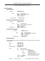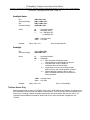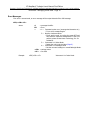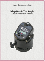
1
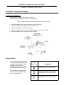
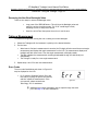
Laser Technology, Inc. MapStar® TruAngle User’s Manual 1st Edition MapStar TruAngle User’s Manual Part Number 0144849 Copyright Notice: Information in this document is subject to change without notice and does not represent a commitment on the part of Laser Technology, Inc. No part of this manual may be reproduced in any form or by any means, electronic or mechanical, including photocopying, recording, or information storage and retrieval systems, for any purpose other than the purchaser’s personal use, without the express written consent of Laser Technology, Inc. Copyright (c) [2010] Laser Technology, Inc. All Rights Reserved. Unauthorized duplication, in whole or in part, is strictly prohibited. First Edition: December 2010 Trademarks: Criterion and MapStar are registered trademarks of Laser Technology, Inc. All other trademarks are the property of their respective owner. This product is covered by pending patent applications and the following issued patents: 5,859,693 How to Contact LTI: Street Address: Phone: Fax: Web Site: Email: 7070 South Tucson Way Centennial, CO 80112 USA 1-303-649-1000 1-800-790-7364 (USA and Canada) 1-649-9710 www.lasertech.com [email protected] LTI MapStar TruAngle User’s Manual First Edition Copyright (c) [2010] Laser Technology, Inc. All Rights Reserved. Unauthorized duplication, in whole or in part, is strictly prohibited. Table of Contents - Page 1 Table Of Contents Precautions ____________________________________________________________ 2 Section #1 - Introducing the MapStar TruAngle ______________________________ Basic Package ............................................................................................................ Accessories ................................................................................................................ 2 3 3 Section #2 - Quick Start __________________________________________________ 3 Section #3 - Using the TruAngle ___________________________________________ 4 Loading the Batteries .................................................................................................. 4 Battery Indicator .................................................................................................. 4 Attaching the Side Brackets and the Laser .................................................................... 5 Connecting the Cables ................................................................................................ 6 Cable Crimp ......................................................................................................... 6 Leveling the TruAngle ................................................................................................ 6 Fine Adjust and Friction Lock ....................................................................................... 7 Button Names and Functions ....................................................................................... 7 Power ON the TruAngle ........................................................................................ 7 Extend the Display Segment Test ........................................................................... 8 Power OFF the TruAngle ....................................................................................... 8 Display the Firmware Version Number .................................................................... 8 Turn the LCD Backlight On or Off ........................................................................... 8 Indexing the Encoder .................................................................................................. 9 Zeroing the Unit ......................................................................................................... 9 Entering A Non-Zero Backsight .................................................................................... 9 Removing the Non-Zero Backsight Value ................................................................ 10 Taking a Measurement ................................................................................................ 10 Error Codes .......................................................................................................... 10 Section #4 - Managing Serial Data _________________________________________ NMEA Compliance ....................................................................................................... Laser Settings ............................................................................................................ Remote Triggering ...................................................................................................... Format Parameters ..................................................................................................... Serial Ports Pin-out Assignments .................................................................................. Serial Commands ........................................................................................................ Serial Requests ..................................................................................................... Instrument Identification ................................................................................. Serial Commands .................................................................................................. Zero the Display ............................................................................................. Report Current Angle (shown on the LCD) ........................................................ Power Down the TruAngle ............................................................................... Time Out Interval ........................................................................................... Backlight Status .............................................................................................. Backsight ....................................................................................................... TruPulse Series Only ............................................................................................. Error Messages ..................................................................................................... 11 11 11 11 12 12 12 12 12 13 13 13 13 13 14 14 14 15 Section #5 - Caring for the TruAngle _______________________________________ 16 Section #6 - Troubleshooting & Tips _______________________________________ 17 Section #7 - Specifications _______________________________________________ 18 Section #8 - LTI Limited Warranty _________________________________________ 19 Index _________________________________________________________________ 21 LTI MapStar TruAngle User’s Manual First Edition Copyright (c) [2010] Laser Technology, Inc. All Rights Reserved. Unauthorized duplication, in whole or in part, is strictly prohibited. Table of Contents - Page 2 Precautions Do not expose to extreme temperatures. TruAngle components are rated for a operating temperature range of -30 C to 50 C (-22 F to 122 F). Storage temperature range: -40 C to 80 C (-40 F to 176 F). Do not expose to severe mechanical shock. To do so may damage the TruAngle’s encoder or associated electronics. See the required procedure for indexing the encoder (Page 9). Do not expose to excessive moisture or dust. The TruAngle is rated IP54 - water & dust resistant. See Page 16 for information about the care and maintenance of the TruAngle. Section #1 - Introducing the MapStar TruAngle Congratulations on the purchase of your LTI MapStar TruAngle angle encoder. The TruAngle calculates a turned horizontal angle that can be referenced to any desired point or direction. It works in conjunction with all our laser rangefinders that have an inclinometer for complete 3D position measurements with X, Y and Z coordinates. The modular design allows you to pivot the laser a full 90 up or down while maintaining the rotary encoder level, providing the greatest possible accuracy and range of motion. One of the major advantages of the TruAngle is that it is not affected by local magnetic interference. There are so many applications, like urban environments for example, where you may need to position objects, but can not use an electronic compass because your surroundings could compromise your accuracy. Features of the TruAngle: • • • • • • Simple 2-button interface Friction Lock Mechanism Bubble Level LCD Backlight Serial Interface with Auto Download from laser to data collector 1. Bubble Level 2. Serial Ports 3. Threaded Insert 4. Tripod Mount 5. Fine Adjust 6. Friction Lock 7. Buttons 8. LCD 9. Battery Door Top View Right Side View Figure #1 LTI MapStar TruAngle User’s Manual First Edition Copyright (c) [2010] Laser Technology, Inc. All Rights Reserved. Unauthorized duplication, in whole or in part, is strictly prohibited. Section #2 - Quick Start - Page 3 Basic Package MapStar TruAngle Laser Cable Download Cable Side Brackets (1 set): • Short (Impulse / TruPulse) or • Tall (UltraLyte) 2 AA batteries User's Manual Padded shipping box Accessories Laser mounting brackets Tripod / Staff Tribrach & Tribrach adapter Mounting hardware Serial data cable (remote trigger option) Carrying case Software solutions Data Collectors To learn more about any of the items listed above, please contact LTI, LTI Sales Representative or Authorized Dealer. Section #2 - Quick Start 1. Install the batteries (Page 4). 2. Mount side brackets, laser, tripod and then attach cables (Pages 5 - 6). 3. Use the bubble level to level the unit (Page 6). 4. Long press the ON button to power on the unit (Page 7). 5. Index the encoder (Page 9). 6. Zero the unit when “0.00” is flashing by pressing the OK button or firing the laser. When the TruAngle is rotated, the display not flash and will update with angle measurements. 7. Fire the laser to take an angle measurement. Laser and angle measurement data is automatically downloaded through the DATA serial port. 8. When finished, long press both buttons to power off the TruAngle. Figure #2 LTI MapStar TruAngle User’s Manual First Edition Copyright (c) [2010] Laser Technology, Inc. All Rights Reserved. Unauthorized duplication, in whole or in part, is strictly prohibited. Section #3 - Using the TruAngle - Page 4 Section #3 - Using the TruAngle Loading the Batteries Two AA batteries are required to power the TruAngle. The Battery Door is located on the left side of the TruAngle. Use a flat head screwdriver or coin to remove or secure the battery door. 1. Remove the Battery Door by turning the screw counter-clockwise. Note that Battery Doors tabbed edge serves as the hinge. 2. Insert the two batteries as shown in the figure. 3. Replace the Battery Door by inserting the tabbed edge of the door into the slot. 4. Secure the Battery Door by turning the screw clockwise. Figure #3 Battery Indicator The TruAngle continuously monitors its power source. LTI has defined the acceptable battery voltage range to guarantee correct operation. The battery voltage icon is located in the lower right corner of the LCD. When the battery voltage becomes too low, the unit will automatically power off. No indications. Appearance of the Battery Icon Explanation 2 segments and battery outline lighted. Approximately 8 hours of use remain. 1 segment and battery outline lighted. Approximately 5 hours of use remain. Battery outline lighted. Approximately 2 hours of use remain. LTI MapStar TruAngle User’s Manual First Edition Copyright (c) [2010] Laser Technology, Inc. All Rights Reserved. Unauthorized duplication, in whole or in part, is strictly prohibited. Section #3 - Using the TruAngle - Page 5 Attaching the Side Brackets and the Laser Impulse • The required laser mounting bracket depends upon which laser you are using (Impulse, TruPulse or UltraLyte). Please contact LTI if you need assistance. • When attaching the laser to the side brackets, do not over-extend the side brackets. TruPulse UltraLyte Figure #4 1. Attach the laser mounting bracket to the laser. 2. Attach right and left side brackets to the TruAngle. • The short side brackets are designed for use with the Impulse and the TruPulse. • The tall side brackets are designed for use with the UltraLyte 3. Attach the laser mounting bracket to the side bracket. The side bracket should be secure, but should not be over tightened. LTI MapStar TruAngle User’s Manual First Edition Copyright (c) [2010] Laser Technology, Inc. All Rights Reserved. Unauthorized duplication, in whole or in part, is strictly prohibited. Section #3 - Using the TruAngle - Page 6 Connecting the Cables • Connect either end of the supplied laser data cable to the laser’s serial port and the other end to the TruAngle’s serial port labeled “LASER”. • Connect one end of the download cable to the data collector and the other end to the TruAngle’s serial port labeled “DATA”. Figure #5 Cable Crimp As Figure #6 shows, the side bracket design includes a cable crimp. You can use the cable crimp to hold the cables and keep them from interfering with your work. Figure #6 Leveling the TruAngle The bubble level is used to level the TruAngle. 1. Look at the position of the bubble within the bubble level. When the bubble is centered inside the circle, the TruAngle is level. 2. To align the bubble within the circle, adjust the tribach or tripod the TruAngle is mounted on. Looking at Figure #7, the yellow dot represents the bubble. [A] shows that the TruAngle is not level. [B] shows that the TruAngle is level. [A] [B] Figure #7 LTI MapStar TruAngle User’s Manual First Edition Copyright (c) [2010] Laser Technology, Inc. All Rights Reserved. Unauthorized duplication, in whole or in part, is strictly prohibited. Section #3 - Using the TruAngle - Page 7 Fine Adjust and Friction Lock • The Fine Adjust wheel lets you precisely control the encoder’s rotation. Movement of the wheel results in small angle update measurements. The Fine Adjust ratio is 66:1. • Tightening the Friction Lock keeps the encoder from rotating by adding friction to the base plate and to the brake shoe which is attached to the chassis. Adjust as needed. Button Names and Functions Button ON Function Long press powers on the TruAngle. Shows the Display Test at power on until the button is released (Page 8). BL When the TruAngle is already powered on, long press to turn on / off the backlight. OK Short press to accept orientation and reference the TruAngle at the value displayed. ZERO BS Long press to activate the Zero Mode. Short press to activate the Backsight Mode. Press and hold both buttons until the TruAngle powers off. Figure #7 This manual simplifies the button names to relate to current function instead of matching the TruAngle’s label. For example, instead of “Press the ON BL OK button to activate the backlight”, this manual would state “Press the BL button to activate the backlight”. Power ON the TruAngle To power on the TruAngle, long press the ON button. Briefly, the LCD should look like Figure #8 and the backlight will also be on. Next the LCD should look like Figure #9, prompting you to index the encoder (Page 9). Figure #8 Figure #9 LTI MapStar TruAngle User’s Manual First Edition Copyright (c) [2010] Laser Technology, Inc. All Rights Reserved. Unauthorized duplication, in whole or in part, is strictly prohibited. Section #3 - Using the TruAngle - Page 8 Extend the Display Segment Test Extending the Display Segment Test allows you to verify that all display indicators are working properly. 1. Press and hold the ON button. The LCD should look like Figure #8 (Page 7) and the Backlight should also be on. 2. Verify all display segments are lit. 3. Release the ON button. Upon releasing the ON button, the LCD should look like Figure #9 (Page 7). Power OFF the TruAngle To power off the TruAngle, long press both buttons simultaneously. • To help save its batteries, the TruAngle has a factory-defined power off interval. The instrument will automatically power off if there is no activity for a period of 60 minutes. Instrument activity includes button presses and measurements. • The power off interval may be changed using the Time Out Interval serial command (Page 13). Display the Firmware Version Number The firmware version number provides manufacturing information about your TruAngle. It can only be viewed at power on. 1. Starting with the TruAngle powered off, long press both buttons. As an example, Figure #10 shows the firmware version number 1.14. Note: Your TruAngle may display a different firmware version number. Figure #10 2. Upon release of the buttons, the LCD should look like Figure #9, prompting you to index the encoder (Page 9). For future reference, make note here of the firmware version number: __________. Turn the LCD Backlight On or Off When working in low-light conditions, you may find it easier to read the display screen if the LCD backlight is toggled on. Long press the BL button at anytime to toggle the LCD backlight on or off. To conserve battery power, you should only use the backlight when necessary. LTI MapStar TruAngle User’s Manual First Edition Copyright (c) [2010] Laser Technology, Inc. All Rights Reserved. Unauthorized duplication, in whole or in part, is strictly prohibited. Section #3 - Using the TruAngle - Page 9 Indexing the Encoder Each time the TruAngle is powered on, the LCD will display “ind” (see Figure #9 on Page 7) prompting you to index the encoder. 1. Rotate the TruAngle clockwise or counter clockwise one complete rotation (360). 2. Once the index has been found, the 0.00 LCD characters will flash. As you are rotating the TruAngle, the index may be found before the unit has been rotated the complete 360This is not a problem and will not change the calibration. Zeroing the Unit Once the encoder is indexed, the 0.00 LCD characters will flash to prompt you to zero the unit. 1. Short press the OK button or fire the laser. Firing the laser downloads a serial data string to zero the unit. 2. The 0.00 LCD characters will be displayed steady instead of flashing. Angle measurements and the display will update as the unit is rotated. Entering A Non-Zero Backsight Shooting a BackSight is the process of pairing a reference angle, or BackSight angle, with a selected direction, and must be done upon every change of station. The default is to Zero your backsight angle while this routine allows you to enter a non-zero backsight value. 1. Power on the TruAngle, index the encoder, and then short press the OK button to enter the Measurement Mode. 2. Short press the BS button to activate the Backsight Mode and start updating the display. The display flashes during this process. 3. Rotate the TruAngle until the desired Backsight value is displayed. Use the Fine Adjust wheel to assist in displaying the correct value. Note that some hundredths values will not display - simply stop at the nearest value. 4. Short press the BS button to freeze or lock the number in the display. The number will remain solid and will not update if the TruAngle is turned. 5. Rotate the TruAngle until the instrument is pointing in the desired direction. At this point, if you want to change the backsight value, just short press the BS button. The display will be flashing, prompting you to enter the new backsight value. 6. Press the OK button or fire the laser on the target to accept the measurement. The display & backlight will flash 3 times, indicating the new backsight value has been set. The display will be steady instead of flashing. The unit is ready for the next angle measurement. LTI MapStar TruAngle User’s Manual First Edition Copyright (c) [2010] Laser Technology, Inc. All Rights Reserved. Unauthorized duplication, in whole or in part, is strictly prohibited. Section #3 - Using the TruAngle - Page 10 Removing the Non-Zero Backsight Value There are two ways to remove the Backsight value: • Long press of the ZERO/BS button. This will clear the Backsight value and return the unit to the zeroing mode. The “0.00” would begin to flash, indicating the unit is ready to be zeroed. • Power the unit off and then power the unit on to set the zero. Taking a Measurement To measure an angle after zeroing the unit or setting a non-zero backsight: 1. Rotate the TruAngle until the instrument is pointing in the desired direction. 2. Fire the laser. • • • When laser is fired and a measurement is recorded, the TruAngle will also record the current angle measurement and display that angle measurement on the LCD. The measurement display and backlight will flash three times. Then the angle measurement will display steady. The flash indicates the measurements are being downloaded through the data serial port automatically. The TruAngle is ready for a new angle measurement. 3. Repeat steps 1 and 2 for each new measurement. Error Codes The error code listed below and shown in Figure #11 may be displayed on the LCD: • Err 2: Memory Checksum Failure. If you see this code, try cycling the power OFF and ON, and then repeat the measurement. If the error persists, please contact Laser Technology, Inc. for assistance. Figure #11 Additional error codes (messages) may be output through the serial port. See Page 15 for more information. LTI MapStar TruAngle User’s Manual First Edition Copyright (c) [2010] Laser Technology, Inc. All Rights Reserved. Unauthorized duplication, in whole or in part, is strictly prohibited. Section #4 - Managing Serial Data - Page 11 Section #4 - Managing Serial Data The TruAngle's two serial ports are used to communicate with external devices. The one labeled LASER to an LTI laser product and the one labeled DATA to a data collector or PC. In normal operation, the laser’s Fire button is pressed and data is automatically downloaded to the TruAngle. It then fires, inserts the angle value into the data string and automatically sends it out the DATA port. In addition, commands can be sent from the data collector/PC to the TruAngle or laser; such as parameter change commands (Page 13) and a remote trigger command to Fire the laser (see below). Figure #12 shows the data flow. Figure #12 The cables, data collectors, and software needed for remote operations are available from LTI or an Authorized Dealer. NMEA Compliance The TruAngle uses the LTI CR400 data format follows the guidelines of the NMEA 0183 Standard for Interfacing Marine Electronic Navigational Devices, Revision 2.0: • • NMEA 0183 provides for both standard and proprietary data formats. Since none of the standard formats are useful for the data transferred from the Impulse, special proprietary formats are used. Rules described in the NMEA standard governing general message structure, leading and trailing characters, numeric values, delimiting character, checksums, maximum line length, data rate, and bit format are followed exactly. As required by NMEA 0183, the CR400-format does not respond to unrecognized header formats, malformed messages, or messages with invalid checksums. Laser Settings Impulse 200 and 200 LR: Select the CR400 message format and the Auto Download option. The Impulse will not communicate with the TruAngle if the IP200 download format is active. TruPulse Series: The CR400 message format with Auto Download is only option offered in the unit. No settings are necessary UltraLyte 200 and 200 LR: Select the CR400 message format. The UltraLyte will not communicate with the TruAngle if the UL200 download format is active. Remote Triggering It is possible to remotely trigger the TruAngle by using an external computer, data collector, or switch closure. Remote triggering uses an open collector closure to ground or an active low TTL or RS232 level signal to the 'trigger' pin on the serial connector. It requires a special order download cable that connects the remote trigger signal from the encoder to the 'RTS' output signal of a computer's serial port. When using a serial cable with a remote trigger connection hard-wired, care must be taken to control the state of the RTS signal from the host computer. Often times the default state of the RTS signal will be low, causing an inadvertent trigger. Since the remote trigger signal is treated the same as a button press on the TruAngle, holding the signal low is identical to holding down a button, which prevents a response to any additional buttons that are pressed. LTI MapStar TruAngle User’s Manual First Edition Copyright (c) [2010] Laser Technology, Inc. All Rights Reserved. Unauthorized duplication, in whole or in part, is strictly prohibited. Section #4 - Managing Serial Data - Page 12 Format Parameters The TruAngle serial interface uses RS-232 12V signal levels and data format. The format parameters are set to: • Baud Rate 4800 BPS • Start bit 1 • Data bits 8 • Stop bit 1 • Parity None Serial Ports Pin-out Assignments Figure #13 Serial Commands • Serial commands that start the “$” character pass through the TruAngle to the laser. For information about these serial commands, please refer to the user’s manual that shipped with your laser. • Serial commands that start with the “#” character are intercepted and acted upon by TruAngle. • TruPulse Series Lasers Only: Serial commands can be sent to the TruPulse series laser via a PC, while cabled to the TruAngle. For example, the $GO command will fire the TruPulse, capture a measurement, and then download the serial data string from the TruPulse to TruAngle, capture the angle measurement and then download the complete serial data string to the PC. For more TruPulse commands please refer to the user’s manual that shipped with your TruPulse. Serial Requests Instrument Identification Command: $ID<CR><LF> where: Instrument Reply: Example Reply: # ID <CR> <LF> = = = = message identifier refers to TruAngle Firmware Version carriage return line feed #ID,LCAE,version number,date<CR><LF> #ID,LCAE,1.14,07-28-10<CR><LF> LTI MapStar TruAngle User’s Manual First Edition Copyright (c) [2010] Laser Technology, Inc. All Rights Reserved. Unauthorized duplication, in whole or in part, is strictly prohibited. Section #4 - Managing Serial Data - Page 13 Serial Commands Zero the Display Command: #ZERO<CR><LF> where: # ZERO <CR> <LF> Instrument Reply: = = = = message identifier refers to Zero the Display carriage return line feed #OK<CR><LF> Report Current Angle (shown on the LCD) Command: #ANG<CR><LF> where: # = message identifier ANG = refers to Report the Current Angle <CR> = carriage return <LF> = line feed #ANG,23.96<CR><LF> Example Reply: Power Down the TruAngle Command: #PWR<CR><LF> where: Example Reply: # = message identifier PWR = refers to Power Down the TruAngle <CR> = carriage return <LF> = line feed #OK<CR><LF> Time Out Interval The factory default Time Out Interval is 60 minutes (Page 8). This command allows you to change the Time Out interval. Get: Reply: #TO<CR><LF> #TO,n<CR><LF> Set: Instrument Reply: #TO,n<CR><LF> #OK<CR><LF> where: # TO Example: = message identifier = refers to the Time Out Interval n = 5 5-minute time-out 10 10-minute time-out 60 60 for 60-minute time-out XXXXX XXXXX-minute time-out (any number between 0 and 65534) 65535 No Time Out Interval. Always on. <CR> = carriage return <LF> = line feed #TO,10<CR><LF> Sets the Time Out Interval to 10 minutes. LTI MapStar TruAngle User’s Manual First Edition Copyright (c) [2010] Laser Technology, Inc. All Rights Reserved. Unauthorized duplication, in whole or in part, is strictly prohibited. Section #4 - Managing Serial Data - Page 14 Backlight Status Get: Instrument Reply: Set: Instrument Reply: #BL<CR><LF> #BL,n<CR><LF> #BL,n<CR><LF> #OK<CR><LF> where: # BL n = message identifier = Backlight Status = 0 = Backlight OFF 1 = Backlight ON <CR> = carriage return <LF> = line feed Example: #BL,1<CR><LF> Turns the backlight ON. Backsight Set: Instrument Reply: #BS,n<CR><LF> #OK<CR><LF> where: # BS n = message identifier = Backsight = 1 = Puts instrument in Backsight mode (display flashes so display angle can be set). 2 = Locks Backsight angle in display so instrument can be aimed at target. 3 = Locked angle is set as current angle, display flashes 3 times, and normal operation resumes. 4 = Cancels Backsight operation after a #BS,1 or #BS,2 command and returns the instrument to normal operation. <CR> = carriage return <LF> = line feed Example: #BS,1<CR><LF> Turns on the backlight. TruPulse Series Only Serial commands can be sent to the TruPulse series via PC, while cabled to the TruAngle. For example, the $GO command will fire the laser and capture a measurement. Then the TruPulse will download the serial string into the TruAngle, capture the angle measurement and download the data string to the PC. For information about additional commands, please refer to the user’s manual that shipped with your TruPulse. LTI MapStar TruAngle User’s Manual First Edition Copyright (c) [2010] Laser Technology, Inc. All Rights Reserved. Unauthorized duplication, in whole or in part, is strictly prohibited. Section #4 - Managing Serial Data - Page 15 Error Messages If an error is encountered, an error message will be output instead of the #OK message. #ER,n<CR><LF> where: Example: # ER = message identifier = Error n = 1 = Command syntax error (unrecognized character etc.) *Try to enter command again. 2 = Memory checksum failure *If you see this code, try cycling the power OFF and ON, and then repeat the measurement. If the error persists, please contact Laser Technology, Inc. for assistance. 3 = Instrument is in Index Mode *Rotate the unit to set the index (Page 9). 4 = Instrument is in Backsight Mode *Set the non-zero backsight or cancel Backsight Mode. <CR> = carriage return <LF> = line feed #ER,3<CR><LF> Instrument is in Index Mode. LTI MapStar TruAngle User’s Manual First Edition Copyright (c) [2010] Laser Technology, Inc. All Rights Reserved. Unauthorized duplication, in whole or in part, is strictly prohibited. Section #5 - Caring for the TruAngle - Page 16 Section #5 - Caring for the TruAngle Operating Temperature The TruAngle components are rated for a temperature range of -22 to 122 F (-30 to 50 C). Do not expose the instrument to temperatures outside this range. Moisture and Dust Protection The Angle Encoder is sealed to provide protection from normally expected field conditions. It is protected from dust and water, and features temporary submersion resistance. If water leakage is suspected: 1. Power OFF the Angle Encoder. 2. Remove the batteries. 3. Air-dry the encoder at room temperature with the battery compartment open. Shock Protection The TruAngle is a precision instrument and should be handled with care. It will withstand a reasonable drop shock. If the encoder is subjected to a severe mechanical shock, you should power on the instrument and index the encoder (Page 9). Cleaning and Storage Clean the TruAngle after each use. Before returning it to its case, check for the following items: • Excess moisture. Towel off excess moisture, and air-dry the instrument at room temperature with the battery compartment open and the batteries removed. • Exterior dirt. Wipe exterior surfaces clean. Use isopropanol to remove dirt and fingerprints from the exterior surfaces. • Batteries. If you do not expect to use the TruAngle again soon, remove the batteries before storing it. Display Screen It is a good idea to periodically check the display screen to make certain that all display segments are working properly. For more information, see Extend the Display Segment Test (Page 8). LTI MapStar TruAngle User’s Manual First Edition Copyright (c) [2010] Laser Technology, Inc. All Rights Reserved. Unauthorized duplication, in whole or in part, is strictly prohibited. Section #6 - Troubleshooting & Tips - Page 17 Section #6 - Troubleshooting & Tips If you see this issue… … take this action The angles output by the TruAngle do not appear to be accurate. Make sure the TruAngle is level before you power it On (Page 6). When mounting the TruAngle, make sure the base is completely tight to the top of the tripod, adapter or staff you are using; and does not rotate. To aid in this, tighten down the friction lock so the entire unit will not rotate. When turning the unit, the gears seem to grind. Loosen the friction lock until it moves smoothly. After referencing the TruAngle, the data strings are not being output. The display is updating when rotated but now it is flashing. The ZERO/BS button was inadvertently pressed. Cycle the Power Off/On, and re-reference the unit and try again. The display reads “ind” and will not go into the Zero backsight mode. Rotate the TruAngle through 360 degrees until the display starts to flash “0.00”. LTI MapStar TruAngle User’s Manual First Edition Copyright (c) [2010] Laser Technology, Inc. All Rights Reserved. Unauthorized duplication, in whole or in part, is strictly prohibited. Section #7 - Specifications - Page 18 Section #7 - Specifications Accuracy: 0.1 staff mounted 0.05 tripod mounted Range: 0 to 359.99 Display Resolution: 0.01 Angle Resolution: 0.01 Measurement Units: Degrees Power supply: 2 AA batteries 8 hours continuous use Environment: Water and Dust Resistant: Temperature: Operating: Storage: Size: Height to top of bubble level: Diameter: Width with tall side brackets: Width with short side brackets: Short Side Bracket total height: Tall Side Bracket total height: Weight: 2.25 lbs (1.02 kg) Weight includes batteries, does not include side brackets Construction: Fiberglass filled polycarbonate Tripod Mount: 5/8 inch threaded insert Data Output: RS232 Serial - NMEA 0183 format Sensor Type: High resolution optical encoder IP54 -22 F to +122 F (-30 C to +50 C) -40 F to +176 F (-40 C to +80 C) 5.6 in 4.55 in 5.65 in 5.41 in 10.43 in 15.08 in 14.2 cm 11.6 cm 14.4 cm 13.7 cm 26.5 cm 38.3 cm LTI MapStar TruAngle User’s Manual First Edition Copyright (c) [2010] Laser Technology, Inc. All Rights Reserved. Unauthorized duplication, in whole or in part, is strictly prohibited. Section #8 - LTI Limited Warranty - Page 19 Section #8 - LTI Limited Warranty What is Covered? Laser Technology, Inc. (LTI) warrants this product to be in good working order. Should the product fail to be in good working order at any time during the warranty period, LTI will, at its option, repair or replace this product at no additional charge. Parts and products that have been replaced as a result of a warranty claim become the property of LTI. What is the Period of Coverage? This warranty remains in force for one year from the date of purchase from LTI or an authorized LTI product dealer; unless otherwise noted by LTI at the time of sale. LTI reserves the right to require written verification of the date of the original purchase of any product. What is Not Covered? LTI has no obligation to modify or upgrade any product once sold. Any reproduction of software products is strictly forbidden. This limited warranty does not include service to repair damage to the product resulting from: • Accident • Disaster • Misuse • Abuse • Non-LTI modification • Batteries or damage caused by batteries used in our products. In no event will LTI be liable to you for any damages, including any lost profits, lost savings, or other incidental or consequential damages arising out of the use or inability to use such product. Furthermore, LTI shall not be held responsible if an LTI authorized dealer has been advised of the possibility of such damage, or for any claim by any other party. What Will We Do to Correct Problems? If this product is not in good working order as warranted above, your sole remedy shall be repair or replacement as provided above. How does State Law Relate to this Warranty? LTI hereby disclaims all other express and implied warranties for the product, including the warranties of merchantability and fitness for a particular purpose. Some states do not allow the exclusion of implied warranties, so the above limitations may not apply to you. LTI MapStar TruAngle User’s Manual First Edition Copyright (c) [2010] Laser Technology, Inc. All Rights Reserved. Unauthorized duplication, in whole or in part, is strictly prohibited. Section #8 - LTI Limited Warranty - Page 20 How do You Get Service? In the unlikely event that your LTI product should require warranty or repair service, contact us to receive a Return Merchandise Authorization (RMA) number before returning your product. Laser Technology, Inc. 7070 South Tucson Way Centennial, CO 80112 USA Phone: 1-303-649-1000 1-800-790-7364 (USA and Canada) Fax: 1-303-649-9710 Email: [email protected] Web Site: www.lasertech.com If the product is delivered by mail, you agree to insure the product or assume the risk of loss or damage in transit. In addition, the shipping container or equivalent, will be sent prepaid and for doorto-door delivery. About the Warranty Validation Card It must be completed and received by LTI in order to benefit from this limited warranty. If an LTI software product requires registration, this must also be completed to benefit from this limited warranty. Receipt of the warranty validation card not only activates the limited warranty, it also allows LTI to contact you directly when hardware or software upgrades become available. If you prefer to register your LTI product electronically, please send an email with all pertinent information to [email protected]. LTI MapStar TruAngle User’s Manual First Edition Copyright (c) [2010] Laser Technology, Inc. All Rights Reserved. Unauthorized duplication, in whole or in part, is strictly prohibited. Table of Contents - Page 21 Index accessories 3 accuracy 18 angle resoution A features 2 fine adjust 2, 7 firmware version 8 friction lock 2, 7 18 B gear noise range 18 remote trigger 11 report current angle S I 9 T L 6 LASER port 6 laser settings 11 LCD 2, 16 LTI contact information M D data output 18 DATA port 6 dirt 16 display resolution 18 display test 8 drop shock 16 dust protection 16 maintenance 16 measruement 10 measurement units 18 moisture 16 moisture protection 16 N NMEA compliance 11 non-zero backsight 9 removing 9, 10 E 2, 18 OFF button 7 OK button 7 ON button 7 power down 13 power supply 18 powering OFF 8 ON 7 precautions 2 13 sensor type 18 serial data format parameters 12 serial ports 6, 11 pin-out assignments 12 side bracket cable crimp 6 side brackets 5 size 18 specifications 18 17 Impule 5 Impulse 11 ind 7, 17 indexing the encoder instrument id 12 C environmental rating error code Err 2 10 error message serial output 15 R G backlight 8 backlight status 14 backsight 9, 14 basic package 3 batteries 16 installing 4 battery door 2 battery indicator 4 BL button 7 BS button 7 bubble level 2 positioning 6 buttons 7 cable connections 5, cable crimp side bracket 6 cleaning 16 construction 18 F 20 temperature range 2, 16, test LCD 8 threaded insert 2 time out interval 8, 13 tripod mount 2, 18 troubleshooting 17 TruPulse 5, 11, 14 U UltraLyte 5, 11 V version number views 2 8 W O warranty 19 wieght 18 P ZERO button 7 zero the display 13 zeroing the encoder Z 9 18