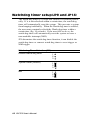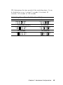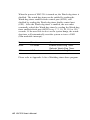
1
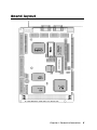
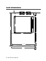
SBC-356
Half-size All-in-one 386SX-40 CPU card
FCC STATEMENT
THIS DEVICE COMPLIES WITH PART 15 FCC RULES.
OPERATION IS SUBJECT TO THE FOLLOWING TWO
CONDITIONS: (1) THIS DEVICE MAY NOT CAUSE HARMFUL INTERFERENCE. (2) THIS DEVICE MUST ACCEPT
ANY INTERFERENCE RECEIVED INCLUDING INTERFERENCE THAT MAY CAUSE UNDESIRED OPERATION.
THIS EQUIPMENT HAS BEEN TESTED AND FOUND TO
COMPLY WITH THE LIMITS FOR A CLASS "A" DIGITAL
DEVICE, PURSUANT TO PART 15 OF THE FCC RULES.
THESE LIMITS ARE DESIGNED TO PROVIDE REASONABLE PROTECTION AGAINTST HARMFUL INTERFERENCE WHEN THE EQUIPMENT IS OPERATED IN A
COMMERCIAL ENVIRONMENT. THIS EQUIPMENT
GENERATES, USES, AND CAN RADIATE RADIO
FREQENCY ENERGY AND , IF NOT INSTATLLED AND
USED IN ACCORDANCE WITH THE INSTRUCTION
MANUAL, MAY CAUSE HARMFUL INTERFERENCE TO
RADIO COMMUNICATIONS. OPERATION OF THIS
EQUIPMENT IN A RESIDENTIAL AREA IS LIKELY TO
CAUSE HARMFUL INTERFERENCE IN WHICH CASE
THE USER WILL BE REQUIRED TO CORRECT THE
INTERFERENCE AT HIS OWN EXPENSE.
Copyright Notice
This document is copyrighted, 1997, by AAEON Technology Inc.
All rights are reserved. AAEON Technology Inc. reserves the
right to make improvements to the products described in this
manual at any time without notice.
No part of this manual may be reproduced, copied, translated or
transmitted in any form or by any means without the prior written
permission of AAEON Technology Inc. Information provided in
this manual is intended to be accurate and reliable. However,
AAEON Technology Inc. assumes no responsibility for its use, nor
for any infringements upon the rights of third parties which may
result from its use.
AMI, Analog Device, Award, Burr-Brown, Carray, DR-DOS IBM,
AT, INM XT, Personal System/2, PS/2, Micro Channel, PC-DOS,
Inlog, Jactech, Microsoft, MS-DOS, NEC, Singular and TI are
Registered trademarks.
Part No. 2007356000 1st Edition
Printed in Taiwan
Oct 1997
Packing list
Before you begin installing your card, please make sure that the
following materials have been shipped:
• 1 SBC-356 CPU card
• 1 6-pin mini-DIN dual outlet adapter for keyboard and PS/2
mouse
• 1 Hard disk drive (IDE) interface cable (40 pin)
• 1 Floppy disk drive interface cable (34 pin)
• 1 parallel port adapter (26-25 pin) and COM port (10-9 pin)
adapter kit
• 1 utility disk with VGA utility programs and drivers
If any of these items are missing or damaged, contact your
distributor or sales representative immediately.
Contents
1
General Information ........................... 1
Introduction ............................................................................ 2
Specifications .......................................................................... 3
Board layout ........................................................................... 5
Card dimensions ..................................................................... 6
2
Installation ........................................... 7
Jumpers and connectors ........................................................ 8
Locating jumpers and connectors ....................................... 10
Setting jumpers ...................................................................... 11
Safety precautions ................................................................ 12
Installing DRAM (SIMMs) .................................................. 13
Watchdog timer setup(JP9, JP14) ....................................... 14
PS/2 Mouse Setup (JP8) ....................................................... 17
Flash EPROM Selection (JP15) ........................................... 17
COM4 Communication setup (JP1, JP12, JP13) .............. 18
IDE Hard Disk I/F (CN10) ................................................... 19
Floppy disk Connector I/F (CN7) ....................................... 20
Serial communication I/F
(CN17, CN14, CN15, CN16, CN 12) ................................... 21
Parallel Port I/F (CON2) ...................................................... 23
VGA Monitor I/F (CN18) .................................................... 24
Flat Panel I/F (CN11)............................................................ 25
Cable and switch connections
(CN1, CN3, CN4, CN5, CN19, CN21, CN6) ...................... 26
DiskOnChip Installation (U9, JP11) ................................... 27
3
AMIBIOS Setup .................................... 29
General information ............................................................. 30
Standard CMOS Setup ........................................................ 31
Advanced CMOS Setup ....................................................... 33
Advanced Chipset Setup ...................................................... 40
Change Suppervisor Password ............................................ 41
Auto Configuration with Optimal settings ......................... 41
Auto Configuration with Fail Safe settings ........................ 41
Save Settings and Exit .......................................................... 41
Exit Without saving .............................................................. 42
4
SVGA Setup ......................................... 43
Windows 3.1 .......................................................................... 44
Driver installation - Windows Setup ........................................ 44
DOS ....................................................................................... 45
SOFTWARE UTILITIES ...................................................... 47
The CHIPSCPL utility program ............................................. 47
Installing the utility .................................................................. 47
Howto use the uitlity ............................................................... 47
A
Watchdog Timer Demo Program .... 49
B
Installing PC/104 Modules ................. 51
Installing PC/104 modules ................................................... 52
C
LCD Display BIOS Configuration ........ 55
CHAPTER
GeneraI
Information
1
This chapter provides background
information for the SBC-356.
Sections include:
· Card specifications
· Board layout
Chapter 1 General Information
1
Introduction
The SBC-356 is an all-in-one CPU card that intergrates VGA
display and Disk-On-Chip card. The SBC-356 is a half-sized card
that is based on the 386SX CPU running at 40MHz and supports
up to 32 MB of Fast Page DRAM. The card has an on-board
Watch-Dog timer, a Buzzer, and battery-backed Real Time Clock.
It comes with AMI BIOS which is mapped to the upper 64K of
memory.
The SBC-356 provides a floppy disk controller, an IDE disk
controller, four high speed serial prots (RS-232/422/485) and
one Multi-mode parallel port (ECC/EPP/ECP). The SBC-356 is
also equipped with VGA controller. It uses C&T F65545 ISA-bus
VGA controller which provides a flat panel I/F (interface) to
support panel displays.
For applications that require Solid State Disk (SSD) memory, the
SBC-356 is equipped with one 32-pin DIP IC socket which can
accommodate DiskOnChip Solid State Disk memory. The SBC356 supports from 2MB up to 24MB of SSD memory.
2 SBC-356 User's Manual
Specifications
· CPU: 386SX 40 MHz
· Bus interface: ISA (PC/AT) bus
· Data Bus: 16 bit
· Chipset: ALI M6117B (Embedded CPU-386SX)
· RAM memory: Fast Page DRAM 512KB to 16 MB with access
time 70 ns or faster. Uses two 72 pin SIMM sockets
· Dsiplay controller: C&T F65545 ISA-bus VGA controller
· Video memory: two 256k*16 DRAM (1MB) and one 256K*16
DRAM(512KB) used for improving performance with color DSTN
panels
· IDE HDD interface: One primary IDE hard disk drive interface
supports up to two IDE HDDs
· Floppy disk drive interface: One floppy disk drive interface
supports up to two floppy disk drives, 5.25"(360KB and 1.2MB) and /
or 3.5" (720KB, 1.44 and 2.88MB)
· Parallel port: One Multi-mode Parallel port(ECC/EPP/ECP
models)
· Serial port: Four high speed serial ports. Three RS-232 and one
RS-232/RS-422/RS-485
· Real time clock: Dallas DS12B887
· Watchdog timer: Jumper configured time interval: 1, 2, 10, 20, 110,
120 seconds
· PC/104 connector: 104 pins for 16-bit bus. Supports PC/104
modules such as Flash/RAM/ROM disk modules and/or PCMCIA
modules
· Solid State Disk (SSD) interface: One 32-pin DIP socket supports
M-system Disk-On-Chip 2000 series, memory capacity from 1MB to
24MB.
· DMA channels: 7
Chapter 1 General Information
3
· Interrupt channels: 15
· Keyboard interface: Yes
· PS/2 mouse support: Yes
· Voltage requirements: +5V, +12V and -12V
· Operating temperature: +0°C to 60°C
· Storage temperature: -25°C to +85°C
· Operating humidity range: 0 to 90% non-condensing
· Storage humidity range: 0 to 90% non-condensing
· Weight (without memory): 260g
·
Dimensions: 19.0(L)*12.5(W)*2.5(H)cm
4 SBC-356 User's Manual
Board layout
Chapter 1 General Information
5
185.00
73.66
26.00
Card dimensions
80.65
19.00
112.00
SBC-356 386 CPU CARD WITH VGA/PANEL REV. A1
122.00
4.50
6 SBC-356 User's Manual
CHAPTER
Installation
2
This chapter describes how to set up the
SBC-356 hardware, including instructions on setting jumpers and connecting
peripherals, switches and indicators. Be
sure to read all safety precautions before
you begin the installation procedure.
Chapter 2 Hardware Configuration
7
Jumpers and connectors
Connectors on the board link it to external devices such as hard
disk drives, a keyboard or floppy drives. In addition, the board has
a number of jumpers that allows you to configure your system to
suit your application. The table below lists the function of each of
the board jumpers and connectors.
Name
CN1
Function
Power connector
CN2
Printer I/F connector
CN3
External reset connector
CN4
Key lock
CN5
Speaker
CN6
HDD LED (indicator)
CN7
FDD I/F connector
CN8
PC/104 I/F (XT Bus)
CN9
PC/104 I/F (AT Bus)
CN10
HDD connector (Primary)
CN11
LCD panel I/F connector
CN12
Serial I/F #4 (RS-422/485)
CN14
Serial I/F #2 (RS-232)
CN15
Serial I/F #3 (RS-232)
CN16
Serial I/F #4 (RS-232)
CN17
Serial I/F #1 connector
CN18
VGA I/F connector
CN19
Keyboard connector
CN21
Keyboard/Mouse connector
U9
Disk On Chip socket
SM1-2
System DRAM socket
JP1
COM4 Communication I/F
JP8
PS/2 interrupt (IRQ12)
JP9
Watch-dog timer out active
JP11
Disk On Chip address selection (DiskOnChip
memory)
8 SBC-356 User's Manual
JP12
RS-422/485 RX control
JP13
RS-422/485 TX control
JP14
Watch-Dog Timer Timeout
JP15
Flash EPROM Select
Chapter 2 Hardware Configuration
9
Locating jumpers and connectors
CN1
CN18
CN21
CN17
CN12
CN14
CN15
CN16
CN8
DS12887A
BIOS
CN10
DALLAS
CN11
F65545 B2
CHIPS
DiskOnChip
JP14
CN7
JP13
JP12
JP15
CN9
MEGA-KB-H-Q
CN6
JP11
14.3C73
JP9
U9
CN4
CN5
CN3
JP8
UM8669F
UMC
JP1
CN2
M6117B
ALI
M5113
ALI
CN19
SM1, SM2
SBC-356 386 CPU CARD WITH VGA/PANEL REV. A1
10
SBC-356 User's Manual
Setting jumpers
You configure your card to match the needs of your application by
setting jumpers. A jumper is the simplest kind of electric switch.
It consists of two metal pins and a small metal clip (often
protected by a plastic cover) that slides over the pins to connect
them. To “close” a jumper you connect the pins with the clip. To
“open” a jumper you remove the clip. Sometimes a jumper will
have three pins, labeled 1, 2 and 3. In this case you would connect
either pins 1 and 2 or 2 and 3.
1
Open
Closed
2
3
Closed 2-3
The jumper settings are schematically depicted in this manual as
follows:
1 2 3
Open
Closed
Closed 2-3
A pair of needle-nose pliers may be helpful when working with
jumpers.
If you have any doubts about the best hardware configuration for
your application, contact your local distributor or sales representative before you make any changes.
Generally, you simply need a standard cable to make most
connections.
Chapter 2 Hardware Configuration
11
Safety precautions
Warning! Always completely disconnect the power cord
from your chassis whenever you are working on
it. Do not make connections while the power is
on because sensitive electronic components can
be damaged by the sudden rush of power. Only
experienced electronics personnel should open
the PC chassis.
Caution!
12
Always ground yourself to remove any static
charge before touching the CPU card. Modern
electronic devices are very sensitive to static
electric charges. Use a grounding wrist strap at
all times. Place all electronic components on a
static-dissipative surface or in a static-shielded
bag when they are not in the chassis.
SBC-356 User's Manual
Installing DRAM (SIMMs)
The SBC-356 are sold without system memory and disk on chip
memory. Memory must be installed prior to using the SBC-356.
The SBC-356 has 2 SIMM (Single In-line Memory Module)
DRAM module sockets. Each socket will accommodate a 72 pin
DRAM module - 1MB, 4MB or 16MB. The memory access time
should be 70ns or less. The SBC-356 can also accommodate
memory modules with parity check bit. EDO DRAM memory
modules are not supported by SBC-356.
Install memory as appropriate at locations SIMM1 - SIMM2.
SM1
SM2
1MB
1MB
1MB
1MB
4MB
4MB
2MB
4MB
4MB
16MB
16MB
To t al Memo r y
8MB
16MB
16MB
32MB
Chapter 2 Hardware Configuration
13
Watchdog timer setup(JP9 and JP14)
The watch-dog timer is a circuit that should be refreshed periodically. If it is not refreshed within a certain time, the watch-dog
timer will automatically reset the system. This prevents a system
from hanging indefinitely. When the Watch-dog tmer is enabled,
the user must constantly refresh the Watch-dog timer within a
certain time (Eg. 10 seconds). If the user falls to do so, the
watch-dog timer will automatically reset the system or issue a
non-maskable interrupt (NMI).
JP9 determines the watch-dog timer function, it can disable the
watch-dog timer or connect watch-dog timer to reset trigger or
NMI trigger.
Watch-dog Timer Selection(JP9)
Disable Watch-dog timer
System Reset (Default)
NMI
14
SBC-356 User's Manual
1
2
3
1
2
3
1
2
3
JP14 determines the time period of the watch-dog timer. It can
be disabled or set as 1 second, 2 seconds, 10 seconds, 20
seconds, 110 seconds or 120 seconds.
Watch-Dog Timer Time Out Selection(JP 14)
1 second
2
1
2 seconds
8
7
10 seconds(Default)
2
1
20 seconds
8
7
2
1
8
7
2
1
110 seconds
2
1
8
7
2
1
8
7
120 seconds
8
7
Chapter 2 Hardware Configuration
15
When the power of SBC-356 is turned on, the Watch-dog timer is
disabled. The watch-dog timer can be enabled by reading the
Watch-dog timer enable/refresh control port (443H), and
disabled by reading the Watch-dog timer disable control port
(43H). After the Watch-dog timer is enabled, the user must
constandly refresh the Watch-dog timer by reading the Watch-dog
timer enable/refresh port (443H) every 1, 2, 10, 20, 110 or 120
seconds. If the user fails to do so or the system hangs, the watchdog timer will automatically reset the system or issue a NMI
(Non-maskable interrupt).
Port
Direction
Function
443H
I/O Read
Enable Watch-Dog Timer
Refresh Watch-Dog Timer
43H
I/O Read
Disable Watch-Dog Timer
Please refer to Appendix A for a Watchdog timer demo program.
16
SBC-356 User's Manual
PS/2 Mouse Setup (JP8)
JP8 determines the PS/2 mouse interrupt signal. The PS/2 mouse
uses IRQ12. If you do not use PS/2 mouse and wish to assign
IRQ12 for other purposes, you may change JP8 to disconnect PS/
2 interrupt from IRQ12.
PS/2 Interrupt select (JP8)
No interrupt for PS/2
IRQ12 (Default)
Flash EPROM Selection (JP15)
JP15 determines the programming voltage of Flash EPROM
BIOS. The SBC-356 BIOS provides plug and play function, it can
automatically reload system configuration to the system BIOS.
The SBC-356 BIOS can use variety Flash EPROM, JP15 must set
according to the Flash EPROM used.
Flash EPROM select(JP15)
Vpp=Vcc (Default)
Vpp=12V
1
1
3
3
Chapter 2 Hardware Configuration
17
COM4 Communication Setup
(JP1, JP12, JP13)
COM4 can also be assigned as RS-422 or RS-485 I/F. Short JP1
to assign COM4 as RS-422/RS-485 I/F, or otherwise assign
COM4 as RS-232 I/F.
COM4 communication select (JP1)
RS-422/RS-485 I/F (Default)
RS-232 I/F
When COM4 is assigned as RS-422/RS-485 I/F, JP12 and JP13
determine the RS-485 transmit and receive enable signals.
COM4 RS-422/RS-485 RX control (JP12)
RX is always enable (Default)
RX is enabled if Port 2EFH D1=1
RX is always disabled
2
1
2
1
5
6
5
6
2
1
5
6
COM4 RS-422/RS-485 TX control (JP13)
TX is always enable (Default)
2
1
8
7
TX is enabled if -RTS=0
2
1
2
1
2
1
8
7
8
7
8
7
TX is enabled if Port 2EFH D0=1
TX is always disabled
18
SBC-356 User's Manual
IDE Hard Disk I/F (CN10)
The SBC-356 provides a 40-pin DIL box header connector
(CN10) for the IDE hard disk interface. The IDE hard disk
interface supports two IDE hard disk drives.
This I/F can be enabled or disabled by BIOS CMOS Setup
settings. If you want to use a ESDI or SCSI interface or you want
to use another IDE interface card, you must disable the BIOS
option " Onboard IDE ".
IDE hard disk connector (CN10)
Pin
1
Signal
Reset
Pin
2
Signal
Ground
3
D07
4
D08
5
D06
6
D09
7
D05
8
D10
9
D04
10
D11
11
D0 3
12
D12
13
D02
14
D13
15
D01
16
D14
17
D00
18
D15
19
Ground
20
N.C.
21
N.C.
22
Ground
23
IOW-
24
Ground
25
IOR-
26
Ground
27
N.C.
28
Bale
29
N.C.
30
Ground
31
PinInterrupt
32
IOCS16-
33
SA1
34
N.C.
35
SA0
36
SA2
37
HDC CS0-
38
HDC CS1-
39
HDD Active
40
Ground
Chapter 2 Hardware Configuration
19
Floppy Disk Connector I/F (CN7)
The SBC-356 provides a 34-pin DIL box header connector (CN7)
for the floppy disk interface. This floppy disk interface supports
two 360KB (5.25"), 720KB (3.5"), 1.2MB (5.25"), 1.44MB (3.5")
and 2.88MB (3.5") floppy disk drive.
This floppy disk interface can be enabled or disabled by BIOS
CMOS Setup setting. If you want to use another floppy disk
interface card, you must disable the floppy disk interface on the
SBC-356.
Floppy Disk Drive Interface (CN7)
20
Pin
1
Signal
Ground
Pin
2
3
Ground
4
5
Ground
6
N.C.
7
Ground
8
Index-
9
Ground
10
Motor Enable A-
11
Ground
12
Driver Select B-
13
Ground
14
Driver Select A-
15
Ground
16
Motor Enable B-
17
Ground
18
Direction-
19
Ground
20
Step-
21
Ground
22
Write Data-
23
Ground
24
Write Gate-
25
Ground
26
Track 0-
27
Ground
28
Write Protect-
29
Ground
30
Read data-
31
Ground
32
Side 1 Select-
33
Ground
34
Disk Change-
SBC-356 User's Manual
Signal
Reduce Write Current-
N.C.
Serial Communication I/F
(CN17, CN14, CN15, CN16, CN12)
The SBC-356 provides four serial communication I/F. These
interfaces can be enabled, disabled and COM port assignable
individually. COM1, COM2 and COM3 are RS-232 I/F, COM4
can be assigned as RS-232 I/F or RS-422/RS-485 I/F.
The following are the pin assignments:
PIN
COM1
COM2
COM3
COM4
Signal
CN17
CN14
CN15
CN16
1
DCD
DCD
DCD
DCD
Data carry detect
(RS-232)
2
RX
RX
RX
RX
Receive data
3
TX
TX
TX
TX
Transmit data
4
DTR
DTR
DTR
DTR
Data terminal ready
5
GND
GND
GND
GND
Ground
6
DSR
DSR
DSR
DSR
Data set ready
7
RTS
RTS
RTS
RTS
Request to send
8
CTS
CTS
CTS
CTS
Clear to send
9
RI
RI
RI
RI
Ring indicator
NC
NC
NC
Not connected
10
CN17 is a male D-type connector, CN14, CN15 and CN16 are 10
pin dual-in-line box header connector.
COM4 can also be assigned as RS-422 or RS-485 I/F.
Chapter 2 Hardware Configuration
21
If COM4 is assigned as RS-422/Rs-485 I/F, CN12 is the COM4
connector, it is a dual-in-line box header connector.
Pin
1
22
COM4
Signal
CN12
(RS-422/RS-485)
TX-
Transmit data
2
TX+
Transmit data
3
RX+
Receive data
4
RX-
Receive data
5
GND
Ground
6
RTS-
Request to send
7
RTS+
Request to send
8
CTS+
Clear to send
9
CTS-
Clear to send
10
NC
Not connected
SBC-356 User's Manual
Parallel Port I/F (CON2)
The SBC-356's parallel port can be enabled or disabled or
configured as a different I/O address, mode (Standard, EPP or
ECP), IRQ channel and DMA channel. All parallel port configurations can be set at BIOS CMOS Setup.
Parallel Port I/F (CN2)
Pin
1
Signal
Strobe-
Pin
14
Signal
Auto FF-
2
D0
15
Error-
3
D1
16
Initialization-
4
D2
17
Printer Select In-
5
D3
18
Ground
6
D4
19
Gronnd
7
D5
20
Ground
8
D6
21
Ground
9
D7
22
Ground
10
Acknowledge-
23
Ground
11
Busy
24
Ground
12
Paper Empty
25
Ground
13
Printer Select
26
N.C.
Chapter 2 Hardware Configuration
23
VGA Monitor I/F (CN18)
The SBC-356 is equipped with an VGA I/F(CN18). CN18 is a 15
pin D-sub type connector.
VGA Monitor I/F (CN18)
Pin number
1
2
24
CN18
R
G
3
B
4
NC
5
GROUND
6
GROUND
7
GROUND
8
GROUND
9
GROUND
10
GROUND
11
NC
12
NC
13
Hsync
14
Vsync
15
NC
SBC-356 User's Manual
Flat Panel I/F (CN11)
The SBC-356 provides a 44-pin box header connector (CN11) for
Flat panel.
SBC-356 Flat panel display connector
Pin
1
Function
+12 V
Pin
2
Function
+12 V
3
GND
4
GND
5
Vcc
6
Vcc
7
ENAVEE
8
GND
9
P0
10
P1
11
P2
12
P3
13
P4
14
P5
15
P6
16
P7
17
P8
18
P9
19
P10
20
P11
21
P12
22
P13
23
P14
24
P15
25
P16
26
P17
27
P18
28
P19
29
P20
30
P21
31
P22
32
P23
33
GND
34
GND
35
SHFCLK
36
FLM
37
M
38
LP
39
GND
40
ENABKL
41
GND
42
ASHFCLK
43
Vcc
44
Vcc
Chapter 2 Hardware Configuration
25
Cable and switch connections
(CN1, CN3, CN4, CN5, CN19, CN21, CN6)
Pin
Power
Reset Switch
Keylock
(CN1)
(CN3)
(CN4)
1
+5V
Reset
Power
2
GND
Gnd
Key
3
GND
*****
Gnd
4
+12v
*****
Lock
5
*****
*****
Gnd
6
*****
*****
*****
7
*****
*****
*****
8
*****
*****
*****
Pin
Speaker
Internal keyboard
(CN5)
(CN19)
(CN21)
Speaker
Clock
Clock
2
N/C
Data
Data
Pull high
3
GND
N/C
N/C
*****
4
+5V
GND
Gnd
*****
5
*****
+5V
+5V
*****
1
External Keyboard
HDD LED
(CN6)
-R/W IDE
CN21 is the keyboard connector. A converter cable is included to
adapt the 5-pin keyboard DIN connector on the keyboard to the 6pin Mini-DIN connector. Connect the keyboard converter cable
to CN21 and connect the other end to the keyboard.
26
SBC-356 User's Manual
DiskOnChip Installation (U9, JP11)
Please refer to the DiskOnChip manual for detailed information
on how to prepare the Disk On Chip function on the SBC-356.
To install DiskOnChip on the SBC-356, follow the instructions
below.
Step 1:
Install the DiskOnChip Memory (DiskOnChip) in U9
sockets.
Step 2:
Set JP11 for the memory address of DiskOnChip
memory.
JP11 determines the memory adddress of DiskOnChip memory.
If you have another add-on card in the system that uses the same
memory, neither the SBC-356 nor the add-on card will function
normally. In this case, please change the memory address.
DiskOnChip address select (JP11)
Disable
1
2
7
8
D8000H-DFFFFH (32KB)
1
7
8
2
E8000H-EFFFFH (32KB)
1
2
D0000H-D7FFFH (32KB)
7
1
2
8
*E0000H-E7FFFH (32KB)
1
2
7
8
7
8
* Default
Chapter 2 Hardware Configuration
27
28
SBC-356 User's Manual
CHAPTER
AMIBIOS Setup
3
This chapter describes how to set BIOS
configuration data.
General information
AMIBIOS Setup configures system information that is stored in
CMOS RAM.
Starting AMIBIOS setup
As POST executes, the following appears;
Hit <DEL> if you want to run SETUP
Press <DEL> to run AMIBIOS setup.
AMIBIOS main menu
The AMIBIOS setup screen appears as follows:
AMIBIOS SETUP — BIOS SETUP UTILITIES
(C) 1995 American Megatrends, Inc. All Rights Reserved
Standard CMOS Setup
Advanced CMOS Setup
Advanced Chipset Setup
Change User Password
Change Supervisor Password
Change Language Setting
Auto Configuration with Optimal Settings
Auto Configuration with Fail Safe Settings
Save Settings and Exit
Exit Without Saving
Standard CMOS setup for changing time, date, hard disk type, etc.
ESC: Exit ¯- :Sel
F2/F3: Color F10: Save & Exit
30
SBC-356 User's Manual
Standard CMOS Setup
The AMIBIOS Setup options described in this section are
selected by choosing the Standard CMOS Setup from the AMIBIOS Setup main menu selection screen, as shown below.
The Standard CMOS Setup screen appears:
AMIBIOS SETUP — STANDARD CMOS SETUP
(C) 1995 American Megatrends, Inc. All Rights Reserved
Date (mm/dd/yyyy):
Time (hh/mm/ss):
Wed Aug 21, 1996
12: 19: 46
Floppy Drive A:
Floppy Drive B:
1.44 MB 3½
Not Installed
Pri Master
Pri Slave
:
:
Type Size
AUTO
AUTO
Cyln
Boot Sector Virus Protection
Month:
Day:
Year:
Head
WPcom
LBA
Sec Mode
On
On
Blk
Mode
On
On
PIO
Mode
AUTO
AUTO
32Bit
Mode
Off
Off
Disabled
Jan - Dec
01-31
1901 -2099
Esc: Exit ¯- :Sel
PgUp/PgDn: Modify
F2/F3: Color
Date, Day and Time Configuration
The current values for each category are displayed. Enter new
values through the keyboard.
Floppy A, Floppy B
Select the appropriate specifications to configure the type of
floppy drive that is attached to the system: 360 KB 5¼", 1.2 MB
5¼", 720 KB 3½", and/or 1.44 MB 3½". The settings have not
been pre-installed.
Chapter 3 AMIBIOS Setup 31
Master Disk, Slave Disk
Select the appropriate values to configure the hard disk type you
are using for the master and the slave. Available types are 1~46,
USER, AUTO, Not Installed, and CDROM. The settings have not
been preinstalled.
Boot Sector Virus Protection
Enabling this option allows the system to issue a warning when
any program (or virus) issues a disk format command or attempts
to write to the boot sector of the hard disk drive. Further confirmation is required before accessing this particular section of the
hard disk drive.
32
SBC-356 User's Manual
Advanced CMOS Setup
Select the Advanced CMOS Setup from the AMIBIOS Setup main
menu to enter Advanced setup.
The Advanced Setup options described in this section are the
standard options as shown on the following screen. The following
configurations are based on manufacture's default settings.
AMIBIOS SETUP — ADVANCED CMOS SETUP
(C) 1995 American Megatrends, Inc. All Rights Reserved
Available Options:
Quick Boot
Enabled
Disabled
BootUp CPU Speed
High
Enabled
BootUp Sequence
A:,C:
BootUp Num-Lock
On
Floppy Drive Swap
Disabled
Floppy Drive Seek
Disabled
Mouse Support
Enabled
Typematic Rate
Fast
System Keyboard
Present
Password Check
Setup
Parity Check
Disabled
Wait For 'F1' If Error
Enabled
Hit 'DEL' Message Display
Enabled
System BIOS Cacheable
Enabled
Hard disk Delay
Disabled
C000, 32k Shadow
Enabled
C800, 32k Shadow
Disabled
D000, 32k Shadow
Disabled
D800, 32k Shadow
Disabled
E000, 32k Shadow
Disabled
E800, 32k Shadow
Disabled
Onboard IDE
Enabled
Onboard FDC
Enabled
Onboard Serial Port1
3F8
Onboard Serial Port2
2F8
Onboard Serial Port3
3E8
Onboard Serial Port3 IRQ
9
Onboard Serial Port4
2E8
Onboard Serial Port4 IRQ
5
Onboard Parallel port
378
Parallel port Mode
SPP
ECP DMA
DMA 3
ESC: Exit ¯- :Sel
Parallel Port IRQ
IRQ 5
PgUp/PgDn: Modify
Flat Panel Display Type
12BTFT NEC 64
F2/F3: Color
DISPLAY MODE
BOTH
Chapter 3 AMIBIOS Setup 33
Quick Boot
Set this option to Enabled to instruct AMIBIOS to boot quickly
when the computer is powered on. This option replaces the old
Above 1 MB Memory Test Advanced Setup option.
Setting
Disabled
Description
Enabled
AMIBIOS does not test system memory above 1 MB.
AMIBIOS test all system memory. AMIBIOS waits up
to 40 seconds for a READY signal from the IDE hard
disk drive. AMIBIOS waits for .5 seconds after sending
a RESET signal to the IDE drive to allow the IDE drive
time to get ready again. AMIBIOS checks for a <Del>
key press and runs AMIBIOS Setup if the key has
been pressed.
AMIBIOS does not wait up to 40 seconds for a
READY signal from the IDE hard disk drive. If a
READY signal is not received immediately from the
IDE drive, AMIBIOS does not configure that drive.
AMIBIOS does not wait for .5 seconds after sending a
RESET signal to the IDE drive to allow the IDE drive
time to get ready again.
You cannot run AMIBIOS Setup at system boot,
because there is no delay for the Hit <Del> to run
Setup message.
Boot Up CPU Speed
This option sets the CPU speed when the computer boots.
Boot Up Sequence
This option sets the sequence of boot drives (floppy drive A:, or
hard disk drive C:) that the AMIBIOS attempts to boot from after
AMIBIOS POST completes.
Boot Up Num Lock
Set this option to Off to turn the Num Lock key off when the
computer is booted so you can use the arrow keys on both the
numeric keypad and the keyboard.
34
SBC-356 User's Manual
Floppy Drive Swap
Set this option to Enabled to permit drives A: or B: to be
swapped. The settings are Enabled or Disabled.
Floppy Drive Seek
Set this option to Enabled to specify that floppy drive will
perform a Seek operation at system boot. The settings are
Enabled or Disabled.
Mouse Support
When this option is set to Enabled, AMIBIOS supports a PS/2type mouse. The settings are Enabled or Disabled.
Typematic Rate
This option specifies the typematic rate of a keyboard.
System Keyboard
This option specifies that a keyboard is attached to the computer.
The settings are Present or Absent.
Primary Display
This option specifies the type of display monitor and adapter
in the computer. The settings are Mono, CGA40x25, CGA80x25,
VGA/EGA, or Absent.
Password Check
This option enables password checking every time the computer
is powered on or every time AMIBIOS Setup is executed. If
Always is chosen, a user password prompt appears every time the
computer is turned on. If Setup is chosen, the password prompt
appears as AMIBIOS is executed.
Parity Check
Set this option to Enabled to check the parity of all system
memory. The settings are Enabled or Disabled.
Chapter 3 AMIBIOS Setup 35
OS/2 Compatible Mode
Set this option to Enabled to permit AMIBIOS to run with IBM
OS/2. The settings are Enabled or Disabled.
Wait for 'F1' if Error
AMIBIOS POST error messages are followed by:
Press <F1> to continue
If this option is set to Disabled, AMIBIOS does not wait for you
to press the <F1> key after an error message. The settings are
Enabled or Disabled.
Hit 'DEL' Message Display
Set this option to Disabled to prevent :
Hit <DEL> if you want to run Setup
from appearing on the first AMIBIOS screen when the computer
boots. The settings are Enabled or Disabled.
System BIOS Cacheable
When this option is set to Enabled, the contents of the F000h
system memory segment can be read from or written to the cache
memory. The contents of the F000h memory segment are always
copied from the BIOS ROM to system RAM for faster execution.
The settings are Enabled or Disabled.
Hard disk Delay
The settings of this option are Disabled, 3 sec, 5 sec, 10 sec, 15
sec.
36
SBC-356 User's Manual
C000,32k Shadow
C800,32k Shadow
D000,32k Shadow
D800,32k Shadow
E000,32k Shadow
E800,32k Shadow
These options control the location of the contents of the 32KB of
ROM beginning at the specified memory location. If no adapter
ROM is using the named ROM area, this area is made available to
the local bus. The settings are:
Setting
Enabled
Description
The contents of C 000h - C7FFh are written to the
same address in system memory (RAM ) for faster
execution.
Cached
Disabled
The contents of the named ROM area are written to
the same address in system memory (RAM) for faster
execution, if an adapter ROM will be using the named
ROM area. Also, the contents of the RAM area can be
read from and written to cache memory.
The video ROM is not copied to RAM. The contents of
the video ROM cannot be read from or written to cache
memory.
Onboard IDE
This option specifies whether the onboard IDE controller is
enabled.
Chapter 3 AMIBIOS Setup 37
Onboard FDC
This option enables or disables the floppy drive controller on the
CPU board.
Onboard Serial Port 1
Onboard Serial Port 2
Onboard Serial Port 3
Onboard Serial Port 4
This option enables a serial port on the CPU board and specifies
the base I/O port address for that serial port.
Onboard Serial Port 3 IRQ
Onboard Serial Port 4 IRQ
This option specify an IRQ to a serial port.
OnBoard Parallel Port
This option enables the parallel port on the CPU board and
specifies the parallel port base I/O port address. The settings are
Disabled, 378h, 278h, 3BCh.
Parallel Port Mode
This option specifies the parallel port mode. ECP and EPP are
both bidirectional data transfer sechemes that adhere to the IEEE
P1284 specification. The settings are:
Setting
EPP
ECP
EPP&ECP
38
Description
The parallel port can be used with devices that adhere
to the Enhanced Parallel Port (EPP) specification.
EPP uses the exiting parallel port signals to provide
asymmetric bidirectional data transfer driven by the
host device.
The parallel port can be used with devices that adhere
to the Extended Capabilities Port (ECP) specification.
ECP uses the DMA protocol to achieve transfer rates
of approximately 2.5 Mbs. ECP provides symmetric
bidirectional communlations.
Use this option to support both EPP and ECP on
the parallel port.
SBC-356 User's Manual
Parallel Port IRQ
IRQ7 is used for the Parallel Port(LPT 1). The IRQ can be
changed to IRQ5, or auto-selected(Auto) .
Flat Panel Display Type
This option specifies the type of flat panel display the BIOS will
support.
Please refer to Appendix C for more information.
Display Mode
This option specifies the mode of display the BIOS will support.
Chapter 3 AMIBIOS Setup 39
Advanced Chipset Setup
Select the Advanced Chipset Setup from the AMIBIOS Setup
main menu to enter the Chipset Setup. The following configurations are based on manufacture's default settings.
This section allows you to configure the system based on the
specific features of the installed chipset. This chipset manages
bus speeds and access to system memory resources, such as
DRAM and the external cache. It also coordinates communications between the conventional ISA bus and the PCI bus. It must
be stated that these items should never need to be altered. The
default settings have been chosen because they provide the best
operating conditions for your system.
AMIBIOS SETUP — ADVANCED CHIPSET SETUP
(C) 1995 American Megatrends, Inc. All Rights Reserved
AT Bus Clock
Slow Refresh
Memory Remap
RAS Precharge time
RAS Active Time Insert wait
CAS Precharge Time Insert Wait
Memory Write Insert Wait
Memory Miss Read Insert Wait
ISA I/O High Speed
ISA Memory High Speed
ISA Write cycle end Insert Wait
I/O Recovery
I/O Recovery Period
On-Chip I/O Recovery
16Bit ISA Insert Wait
40
SBC-356 User's Manual
14. 318/2
120 us
Enabled
1.5T
Disable
Disable
Disable
Disable
Enabled
Enabled
Enabled
Enabled
3.75 us
Enabled
Enabled
Available Options:
Disable
Enabled
ESC: Exit
¯-:Sel
PgUp/PgDn: Modify
F2/F3: Color
Change Supervisor Password
1) Select this option from the main menu
2) Enter the Password and Press <Enter>
3) Retype the Password and Press <Enter>
If you forget the password, please contact your distributor for
another password which you can use to enter the BIOS setup
and change your own password.
Auto Configuration with Optimal
Settings
You can load the optimal default settings for the AMIBOIS setup
options by selecting it from the main menu. The optimal default
settings are best case values that should optimize system performance. If CMOS RAM is corrupted, the optimal settings are
loaded automatically.
Auto Configuration with Fail Safe Settings
You can load the Fail Safe setting for the AMIBOIS setup options
by selecting it from the main menu. The Fail Safe setting provides the most stable settings, though they may not provide
optimal performance. Use this option as a diagnostic aid if the
system is behaving erratically.
Save Settings and Exit
If you select this option press <Enter>, the values entered in the
setup utilities will be recorded in the chipset's CMOS memory.
The microprocessor will check this every time you turn your
system on and compare this to what it finds as it checks the
system. This record is required for the system to operate.
Chapter 3 AMIBIOS Setup 41
Exit Without Saving
Selecting this option and pressing <Enter> lets you exit the Setup
program, without recording any new values or changing old ones.
42
SBC-356 User's Manual
CHAPTER
SVGA Setup
4
The SBC-356 features an on-board
flat panel/VGA interface. This
chapter provides instructions for
installing and operating the software
drivers on the included display driver
diskette.
Windows
3.1
These drivers are designed to work with Microsoft Windows
Version 3.1. You may install these drivers either through Windows
or in DOS.
Driver installation - Windows Setup
1. Install Windows as you normally would for a VGA display.
Run Windows to make sure that it is working correctly.
2. Place the Display Driver Diskette #1 in drive A. In Windows
Program Manager, choose File from the Options Menu. Then
from the pull-down menu, choose Run. At the Command Line
prompt, type A:\WINSETUP. Press the <ENTER> key or click
OK to begin the installation.
At this point the setup program locates the directory where
Windows is installed. For proper operation, the drivers must
be installed in the Windows subdirectory.
3. Press <ENTER> to complete the installation. Once completed, the Display Driver Control Panel appears on the screen.
You can find the icon ChipCPL under the Control Panel allows
you to select and load the installed drivers.
Another method of installing these drivers is through the File
Manager. Click on Drive A:, and then double-click on
WINSETUP.EXE to begin installation.
Changing Display Drivers from Windows
To change display drivers from Windows, select the Windows
Setup icon from the Main window. You will be shown the current
setup configuration. Select Change System Settings from the
Option menu. Click on the arrow at the end of the Display line.
You will be shown a list of display drivers. Click on the driver you
want to select it. Then click on the OK button. Follow the directions to complete the setup.
Changing Color Schemes
44 SBC-355 User's Manual
After you change display drivers, you may notice that the color
scheme used by Windows looks strange. This is because
different drivers have different default colors. You can correct
this by choosing the same color scheme or a new color
scheme. First select the Control Panel from the Main window.
Select the Color icon. You will be shown the current color
scheme. Choose a new color scheme and click the OK button.
DOS
Driver installation - DOS Setup
1. Install Windows as you normally would for a VGA
display. Run Windows to make sure that it is working
correctly. Then exit from Windows.
2. Place the Display Driver Diskette #1 in drive A. Type A:
<ENTER>
to make this the default drive.
3. Type SETUP <ENTER> to run the driver SETUP program.
Press any key to get to the applications list.
4. Using the arrow keys, select Windows Version 3.1 and
press the <ENTER> key. Press the <ENTER> key to select
All Resolutions, then press <END> to begin the installation.
5. At this point you will be asked for the path to your Windows System directory (default C:\WINDOWS). When the
installation is complete, press any key to continue. Press
<ESC> followed by Y to exit to DOS.
6. Change to the directory where you installed Windows
(usually C:\WINDOWS).
7. Type SETUP <ENTER> to run the Windows Setup program.
It will show the current Windows configuration. Use the up
arrow key to move to the Display line and press <ENTER>.
8. A list of display drivers will be shown. Use the arrow keys
to select one of the drivers starting with an asterisk (*) and
press <ENTER>.
Chapter 4 SVGA Setup
45
9. Follow the directions on the screen to complete the setup. In
most cases, you may press <ENTER> to accept the suggested
option.
start Windows with the new display driver.
Changing Display Drivers from DOS
To change display drivers from DOS, change to the Windows
directory and run Setup, repeating steps 4 and 5 from the previous
page. Besides the special display drivers marked by an asterisk
(*), you should be able to use the following standard drivers:
VGA
Super VGA
640 x 480, 16 colors
800 x 600, 16 colors
Panning Drivers
Special panning drivers are provided to allow high-resolution
modes to be displayed on a flat panel or CRT. These drivers will
show a section of a larger screen, and will automatically pan or
scroll the screen horizontally and vertically when the mouse
reaches the edge of the display.
46 SBC-355 User's Manual
SOFTWARE UTILITIES
This chapter describes the operation and installation of the
software utility supplied on the Display Driver Diskettes:
• CHIPSCPL
The CHIPSCPL utility program
This utility program is designed to work with MicrosoftÒ WindowsÔ Version 3.1.
Installing the utility
CHIPSCPL.CPL is a WindowsÔ based utility to select resolutions
and color depth. It is a Control Panel Applet with its own icon that
is automatically installed when installing CHIPS WindowsÔ 3.1
linear drivers. The Control Panel icon is in the Main WindowsÔ
group. To invoke the control panel applet, simply click on the icon.
The driver resolution and color depth take effect only after WindowsÔ is rebooted with the new driver.
How to use the utility
SCREEN SIZE<ALT S> allows you to select from the following
resolutions:
•
•
•
•
640 x 480
800 x 600
1024 x 786
1280 x 1024
Chapter 4 SVGA Setup
47
By selecting the resoution first, it will determine the allowable
selections for color depth.
COLOR <ALT O> allows you to select the number of colors from
the following:
•
•
•
•
•
16(4bits per pixel)
256 (8 bpp)
32K (15bpp)
64K (16bpp)
16M (24bpp)
By selecting the color depth first, it will determine the allowable
selections for resolution.
DPI<ALT P> allows you to select a large or small font.
DISPLAY<ALT D> allows you to select the display type from the
following:
• CRT only
• LCD (Flat Panel) only
• Both CRT and LCD (FLAT Panel)
48 SBC-355 User's Manual
APPENDIX
A
Watchdog Timer
Demo Program
The following demo program illustrates
the programming steps required to
enable, set, and disable the watchdog
timer.
The following sample programs are examples of how to enable,
disable and refresh the Watch-dog timer.
WDT_EN_RF
WDT_DIS
EQU
EQU
0443H
0043H
WT_Enable:
PUSH
PUSH
MOV
IN
POP
POP
RET
AX
DX
DX,WDT_EN_RF
AL, DX
DX
AX
PUSH
PUSH
MOV
IN
POP
POP
RET
AX
DX
DX,WDT_EN_RF
AL, DX
DX
AX
PUSH
PUSH
MOV
IN
POP
POP
RET
AX
DX
DX,WDT_DIS
AL, DX
DX
AX
WT_Rresh:
WT_Disable:
50 SBC-356 User's Manual
;save AX DX
;enable the watch-dog timer
;reco AX, DX
;save AX DX
;refresh the watch-dog timer
;reco AX, DX
;save AX DX
;disable the watch-dog timer
;reco AX, DX
APPENDIX
B
Installing PC/104 Modules
This appendix gives instructions for
installing PC/104 Modules.
Appendix B Installing PC/104 Modules
51
Installing PC/104 modules
The CPU card's PC/104 connectors give you the flexibility to attach
PC/104 expansion modules. These modules perform the functions of
traditional plug-in expansion cards, but save space and valuable slots.
Modules include:
• PCM-3335
386 CPU Module w/ Flat Panel/CRT Interface
• PCM-3600
FAX/Modem Module
• PCM-3420
Fast SCSI-2 Module
• PCM-3200
Sound Module
• PCM-3810
Solid State Disk Module
• PCM-3820
High Density Flash Disk Module
• PCM-3115
PCMCIA Module (two slots)
• PCM-3610
Isolated RS-232 and RS-422/485 Module
• PCM-3660
Ethernet Module
• PCM-3718
30 KHz A/D Module
• PCM-3724
48-Channel DIO Module
• PCM-3910
Breadboard Module
Installing these modules on the CPU card is quick and simple. The
following steps show how to mount the PC/104 modules:
1. Remove the CPU card from your system paying particular
attention to the safety instructions already mentioned.
2. Make any jumper or link changes required to the CPU card now.
Once the PC/104 module is mounted you may have difficulty in
accessing these.
3. Normal PC/104 modules have male connectors and mount
directly onto the main card. However, to ensure better bus
matching, the connectors on the CPU card and the PC/104
module are both female. For this reason, you may need to use the
"male-male" adapter included with the CPU card in order to
properly connect your PC/104 module. (Refer to the diagram on
the following page.)
4. Mount the PC/104 module onto the CPU card by pressing the
module firmly but carefully onto the mounting connectors.
5. Secure the PC/104 module onto the CPU card using the four
mounting spacers and srews.
52
SBC-356 User's Manual
PC/104
Mounting Support
Female
Male
Male
Female
PC/104 Module
PC/104 Mounting
Adaptor
SBC-490
CPU Card
Male
PC/104 Module Mounting Diagram
3.500
3.250
3.775
3.575
3.575
0.200
0.200
0
0.200
0
3.350
3.550
PC/104 module dimensions (inches ±5 %)
Appendix B Installing PC/104 Modules
53
54
SBC-356 User's Manual
APPENDIX
C
LCD Display BIOS
Configuration
This appendix gives instructions for
configuring various LCD displays.
This following table shows the BIOS settings (the first column)
and flat panel model (the third column) that can work for the
specified setting. For other types of flat panels that you need
support to connect with CPU board, please contact our sales
representative or distributor.
Setting Type of Flat Panel
Flat Panel Model
1
2
3
4
5
6
NL6448AC30-10(NEC)
NL6448AC33-18(NEC)
LQ10D41(SHARP)
NL8060AC26-11(NEC)
LM64C08P(SHARP)
LM64P11 (SHARP)
7
8
640x480 12bit Color TFT
640x480 18bit Color TFT
640x480 18bit Color TFT
800x600 18bit Color TFT
640x480 16bit D-S Color STN
640x480 8 bit Dual-Scan
Mono STN
640x480 4 bit Plasma
640x480 8 bit Dual-Scan EL
56 SBC-356 User's Manual
PG6404SORM16-3(OKI)
LJ64H052(SHARP)