1
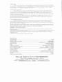
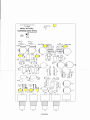
II~
User manual MC2
Thank you for purchasing
on Edwards audio
phono
stage, with core over the correct
installation
we are sure
that it will give many years of pleasure.
CONNECTIONS
The main MC2
should be placed on a separate
arm leads to the sockets marked
additional
Earth or Ground
Depending
additional
Red for RIGHT and White/Block
arrangements
terminal
it mayor
provided
pair of high quality
Connect
your turntables
for LEFT. If you have on
above the input sockets.
may not be necessary to connect
your speakers try connecting/disconnecting
RCA Phono cables (not supplied)
LINE input on your amplifier,
in to any available
shelf next to or near your Turntable.
observing
coble attach this to the GND
on your systems grounding
you can hear a hum through
available
'input'
this wire. Next connect
between the output
sockets and any
this is usuolly marked AUX. Next the Power supply should
AC outlet near to your system then plug the Mini Din into the socket marked
rear of the MC2.
Please observe the polarity
occur. To power 'ON'
this, so if
on
be plugged
DC on the
and do not force the plug into the socket else damage
may
switch on the AC power supply at the wall, there is no power switch on the phono
stage itself.
LISTENING
At this point it may be a good
ideo to try playing
input you used to plug the MC2
heard. Assuming
quietest position
basically
with the position
is not
behind your equipment
Front panel
marked
slowly, hopefully
(or whatever
music will be
ond check that there are no hums or buzzes, if
of the MC2 and or the ground
it is the better it will sound, 011you should
rock the so be it. Dorr't be worried
effect on the MC2's function
connection,
it may well be that the
the
hear is a feint hiss, if this is on the floor
obout where it is, it's position
and orientOtlonWiil-
or reliability.
LED
You can turn off the front panel LED indicator,
diagram
Aux on your amplifier
control
on a shelf at all. There are no hard and fast rules as to where to best position
the quieter
have no detrimental
by selecting
the volume
all is well, lift the needle from the graove
there are, experiment
MC2,
a record
into) and advancing
should you desire by removing
2) from the front of the PCB, This can be accessed
in red on diagram
by removing
1. and sliding the PCB out backwards,
the yellow jumper
(J1 on
the 4 screws on the rear panel
see diagram
1.
MM - operation.
The factory default
set by moving
is the MC setting but if you wish to use this with on Mm or HOMC
the 4 yellow jumpers
jumpers can be accessed
(excluding
the GND
marked J3,J4,J5,J6
by removing
terminal)
so please do not be tempted
in diagram
2 to their alternate
the 4 screws on the rear panel marked
and sliding the PCB out backwards.
positions.
in red on diagram
There are no user serviceable
to ploy or modify any port of the MC2,
Diagram 1
cartridge
this will invalidate
this can be
These
1,
ports inside,
your guarantee.
WARP FILTER,
There is a warp filter function
was chosen as it is around
cone movements
arm/cartridge
2 to their alternate
that it was originally
manufacturer
purchased
can take no responsibility
neglect or through
or loss occurring
unauthorised
during
or from the person claiming
record.
of around
7Hz. This frequency
and helps to remove any excessive
It can be disabled
by moving
2 yellow
positions
UNDER
during
for defects arising from accident,
adjustment
and/or
the first ten years after purchase,
Talk/Edwards
repair,
Audio
dealer or distributor.
The
misuse, abuse, wear and tear,
neither can they accept
responsibility
for damage
under the guarantee.
THE WARRANTY
COVERS Parts and labour
costs for ten
costs. The warranty
costs at anytime.
GUARANTEE
This equipment
was purchased,
free of charge,
from an authorised
date. After ten years you must pay for both parts and labour
does not cover transportation
should
frequency
transit to
years from the purchase
CLAIMS
resonant
GUARANTEE
This entitles you to have the unit repaired
provided
at a very low frequency
in your speakers due to this as you playa
jumpers J14 & J1S on diagram
WORLDWIDE
which operates
the common
should
or failing
be sent carriage
be packed
in the original
this, directly to the Talk/Edwards
prepaid
by a reputable
packing
Audio
carrier - NOT
and returned
distributor
to the deoler from whom
in the country
by post. No responsibility
of residence.
it
It
can be accepted
for
the unit whilst in transit to the dealer or
distributor
and customers
Edwards Audio
directive
are therefore
89/336/EEC
relating
1997
Emissions Standard
ENS0082·1
1997
Immunity
and also the requirements
to insure the unit against
to conform
to EMC by application
ENS0081·1
following
advised
MM 1 has been manufactured
loss or damage
with the protection
of the following
whilst in transit. The
requirements
of the EC Council
standards:·
Standard
of the EC low voltage
directive
relating
to electrical
safety by application
of the
sto ndo rd i-
BSEN/IEC6006S:
high quality
2002
interconnects
International
supplied
Safety standard
by Merlin
Cables.
For the purposes
Compliance
of testing the MC2 was used with the
with the above standards
may only be
made if the unit is
installed as perthis
manual
and using the correct
Specifications.
Max Input MC
Nominal Input
Max Gain MC input (MM)
THD Distortion
Signal to noise
RIM
Frequency response
Stereo separation better than
Input Loading MC/MM
Output impedance
Nominal output.
Max output level
Dimensions WxHxL
Weight
Power consumption (Max)
t~.Jl~
cables.
~
1OmV
0.1- 1mV
63dB(40dB)
<0.006% 1kHz - <0.02% 20kHz
-72dB A-Weighted
within 0.25dB
:
20-1 OOkHz within 0.3dB
55dB - 20-20kHz
1OORwith 2n2/47K with 120pF
< 10 Ohms
1OOmV - 1V
9.8v depending upon input
114.5mm x 47.5mm x 160mm
0.5kg
3.5W
is part of TALK Electronics
3 Eliot Close, Cornberley, Surrey GU15 1LW UK
Telephone 08456 123388 or 07736 421928 - fax 01276 613250
email:- [email protected]
website:www.talkelectronics.com
)jn "o::>"o!pneSPJeMpa"MMM
~"~I\ Z::>IJIJ
1Y!p"17~3
SJINO~lJ313 >llVl
6001:
G) SJlNalDffi
)11\'1
@~
or
z~r
o~r