1
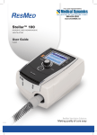
RM CoolClamp Electronically Cooled Universal Cassette Clamp INHECO article number: 7900100 LEICA article number: 14 0502 46537 Operating Manual Revision status V1.1 July 2011 Always keep this manual with the instrument. Read carefully before working with the instrument. BA_RM CoolClamp_11-07-15_7900100RM CoolClamp_V1 1_English.doc Printed in Germany RM CoolClamp INHECO GmbH reserves the right to modify its products in order to improve their quality. These modifications are usually not documented. This operating manual and the information contained in it have been compiled according to the best of our knowledge. INHECO GmbH assumes no liability in the event of printing errors or damage that is caused by printing errors. Trademarks and product names in this operating manual are registered brand names and each belongs to the corresponding owner. INHECO GmbH 3 Contact Contact: INHECO GmbH Fraunhoferstr. 11 82152 Martinsried Germany Phone – Sales 089/899593-101 Phone – Technical Hotline 089/899593-201 Fax E-mail – Sales 089/899593-499 [email protected] E-mail – Technical Hotline Internet [email protected] www.inheco.com This manual belongs to To be filled out by the customer: Series: Serial number. Year of manufacture: Order number: Inventory number Location of instrument setup INHECO GmbH 4 RM CoolClamp Significance of this Operating Manual This operating manual is part of the RM CoolClamp and must remain at the RM CoolClamp until its final destruction. be passed on if the RM CoolClamp is sold or lent. Please contact the manufacturer in the event that you do not understand the operating manual or portions of it. Your opinion regarding the operating manual gives us valuable insights into how we can continue to serve you best. Please do not hesitate to send us your remarks; see the address or telephone numbers on page 4. The safety instructions must be read with the greatest care and attentiveness. They must be understood and observed in order to ensure safe handling of the instrument. Insufficient or lacking knowledge of the contents of the operating manual relieves INHECO GmbH of liability. Therefore the operator should request an orientation from the distributor, Leica Biosystems Nussloch GmbH. INHECO GmbH 5 Contents Contents 1 SYMBOLS IN THE TEXT AND THEIR MEANINGS ............................................................... 7 2 SAFETY NOTES ...................................................................................................................... 8 3 INSTRUMENT SETUP ........................................................................................................... 10 4 ATTACHING TO ROTARY MICROTOMES OF THE LEICA RM22/23.. SERIES WITH QUICK CHANGE SYSTEM ................................................................................................... 15 5 FINE ADJUSTMENT OF THE FORCE BALANCE ............................................................... 16 6 MAINTENANCE WORK TO BE CARRIED OUT BY THE USER ......................................... 17 7 TECHNICAL DATA................................................................................................................ 18 8 DECLARATION OF CONFORMITY ...................................................................................... 19 APPENDIX A: ABBREVIATION GLOSSARY................................................................................. 20 APPENDIX B: INDEX OF FIGURES ............................................................................................... 20 APPENDIX C: TABLES INDEX ....................................................................................................... 20 APPENDIX D: DOCUMENT HISTORY ........................................................................................... 20 INHECO GmbH 6 Symbols in the Text and Their Meanings 1 Symbols in the Text and Their Meanings Notice: Warning! Safety hazard! ! INHECO GmbH Warning of a potential hazard with a low risk of injury. This symbol also warns you of property damage. This symbol indicates useful information for installation, etc. I n f o This arrow is for indicating steps and bullet points. r m a t i o n 7 Safety Notes 2 Safety Notes General use The RM CoolClamp complies with the current technical requirements. The manufacturer has placed the greatest value on user safety. I The following rules apply for the user: n f Rules for accident prevention o General rules for technical safety r The respective specific directives of the EU and other countries m a General use includes handling according to the operating t manual. i o Operation of this unit is intended only for dry ambient conditions without n precipitation of liquids. Defective instruments must not be used. It must be possible for the user to shut off the power supply to the instrument via the power supply unit instantly, if necessary. The following applies in general: Handling specimen head or knife / blade holder, always lock handwheel in place. Release locking mechanism only for sectioning and use knife guard Failure to adjust the force balance may result in injury while working The unit must not be operated in rooms with danger of explosion. The RM CoolClamp must be operated only in the installation orientation and position prescribed for it. It must be ensured that no liquids ingress into the unit. The instrument may be operated indoors only. To keep the thermomechanical stress on the TEC as minimal as possible, the RM CoolClamp should be switched on only once per day and then remain in operation. I n f o Only instructed and trained personnel are permitted to operate this unit. r m a t i o n Who is permitted to operate this unit? INHECO GmbH 8 Safety note Intended use The RM CoolClamp is an electric cooling specimen holder for the universal cassettes and the paraffin-embedded specimens in the cassettes. It is attached I with the specimen holder to the rotary microtomes of the RM22/23.. series. Any n other fuse is improper and therefore not permitted. o r m a safety reasons, no technical modifications to this instrument are For t permitted. Any change or modification that the manufacturer has not i approved causes the warranty to be voided. o Original parts are specially designed for the RM CoolClamp. Parts from n other manufacturers have not been tested and therefore have not been approved and permitted by INHECO GmbH. No liability shall be accepted for any use other than the intended use. Technical modifications Biosafety in the laboratory environment When using the RM CoolClamp in a laboratory environment with biosafety, the user is responsible for labeling the RM CoolClamp according to the WHO Laboratory Biosafety Manual (ISBN 92 4154650 6). In addition, when using the RM CoolClamp the user is responsible for adhering to the rules and regulations depending on the biosafety level with respect to the WHO Laboratory Biosafety Manual. The safety rules and regulations in force for the respective lab must be monitored constantly while work is being carried out with the unit. Malfunctions Report any malfunctions that occur to the person responsible for the instrument immediately. Make sure that the unit has been secured against misuse and abuse. Any safety-related parts that have been removed must be reattached and checked prior to instrument setup. Servicing the RM CoolClamp The unit is not intended to be serviced. Servicing is accomplished by replacement. No repairs may be carried out by the user. Disposing of the unit Dispose of the unit in accordance with the respective environmental directives of the respective country. In the event of contamination, comply with the safety instructions. The RM CoolClamp is RoHS-compliant. INHECO GmbH 9 Instrument Setup 3 Instrument Setup Standard delivery Prior to instrument setup, make sure that the shipment is complete and no part is damaged. The following components should be included in each shipment: RM CoolClamp Power pack with EU, UK, USA and Australia adapters Cable holders for attaching to the microtome (not shown in the figure) Operating manual as a book with 3 languages and on CD with 16 languages (not shown in the figure) Figure 1: Standard delivery The RM CoolClamp can be used only together with the quick change system on the rotary microtomes of the Leica RM22/23.. series. I n f o r m a t i o n INHECO GmbH 10 Instrument Setup General operating instructions To prevent injury and damage, provision must be made for an unobstructed air supply; refer also to the cleaning instructions on page 17. The fan must not be blocked and the air outlet must not be obstructed. Please check before each use that the fan rotates freely. To prevent damage to the RM CoolClamp, the maximum permissible ambient temperature must not be exceeded; for additional information, refer to the specifications on page 18. Ventilation openings, outlet Ventilation openings, inlet Figure 2: Ventilation openings When operating the RM CoolClamp , condensation on the clamp occurs. This is a natural physical process. I n f o r m a t i o n INHECO GmbH 11 Instrument Setup The cable of the RM CoolClamp must be routed to prevent possible severing of the cable when operating the microtome. For this purpose, attach the cable holder to the microtome and then insert the cable into the cable duct. Cable holder position 20 cm high 6 cm lateral Figure 3: Position of the cable duct INHECO GmbH 12 Instrument Setup It is possible for fingers to become pinched in the specimen holder in the event of improper handling. Potential pinching areas Figure 4: Potential pinching areas Select the appropriate adapter for the power supply. To insert or remove the corresponding adapter, the unlocking button must be pressed. I n f o r m a t i o n Figure 5: Power pack with EU, UK, USA and Australia adapters INHECO GmbH 13 Instrument Setup Prerequisite for sectioning the specimens Prerequisite for using the RM CoolClamp: To use it with the rotary microtomes of the RM22/23.. series, a vertical travel rangeI of at least 70mm and an adjustable force balance are necessary. n the non-directional specimen fixture or the directional specimen fixture To use f only XY), bring the specimen fixture into the zero position. (fine or o r The embedded tissue samples to be sectioned must be precooled to -5 °C m using ice or a cooling plate prior to sectioning. [+23 °F] After athe RM CoolClamp's precooling phase of 30 min., the universal cassette t inserted and the sections carried out. can be i o Permitted maximum sectioning speed 420 mm/s n thickness range 0.5 – 600 µm Section Operating concept Installation on a rotary microtome of the RM22/23.. series: The following applies in general: Handling specimen head or knife / blade holder, always lock handwheel in place. Release locking mechanism only for sectioning and use knife guard; see Safety Notes on page 8. ! INHECO GmbH For a microtome that is already configured – remove knife / blade holder with base and specimen clamp. Bring the specimen head into the rear end position (home position). Lock the handwheel in place and, where appropriate, check whether the handbrake has been activated. We recommend working with the non-directional specimen holder fixture – if you will be working with the directional specimen fixture (XY or fine), it must be brought into the zero position. Push the RM CoolClamp with adapter into the dovetail guide of the quick I change system for specimen clamps and tighten it using a size 4 Allen key. n To carry out the force balancing, please observe the operating manual of the f respective microtome under the Operation chapter, Fine Adjustment of the o Force Balance. The specimen head must not fall into the knife after being r stopped/released. m Reinstall the knife / blade holder with base and select the desired clearance a angle. t Attach the cable holder to the microtome; cable holders are included in the i standard delivery of the RM CoolClamp. o n 14 Attaching to the Rotary Microtome of the Leica RM22/23.. Series with Quick Change System 4 Attaching to Rotary Microtomes of the Leica RM22/23.. Series with Quick Change System The RM CoolClamp is attached the same way as changing the universal cassette clamp; for additional information, also refer to the operating manual of the respective rotary microtomes. I There are two versions of the specimen holder fixture, one with and one without n specimen orientation. The two versions can be interchanged. f The specimen orientation allows for simple position correction of the specimen o surface when the specimen is clamped into place. r To do so, proceed as follows: m Move a the specimen holder fixture (60) to the upper end position by turning thet handwheel (12) and engage the handwheel lock. Toi release the clamping system, turn the screw (61) counterclockwise using a size o 4 Allen key. Push n the guide (63) of the RM CoolClamp (62) from the left into the specimen holder fixture (60) as far as it will go. To clamp the specimen clamp, turn the screw (61) clockwise as far as it will go. 60 62 12 63 61 Figure 6: Attaching the RM CoolClamp INHECO GmbH 15 Fine Adjustment of the Force Balance 5 Fine Adjustment of the Force Balance Installing the RM CoolClamp necessitates performance of a force balance; for additional information, also refer to the operating manuals of the respective rotary microtomes. I n If another accessory of a different weight is mounted on the specimen head (33), f you must check whether it is necessary to readjust the force balance. o Checking the correct setting: r Attaching a new accessory and clamping a specimen m Seta the specimen head to half the height of the vertical travel range by turning the handwheel (Figure 7) (9:00 position). t If the specimen head remains in this exact position, the setting is correct. i If the specimen head moves, i.e. it is raised or lowered, fine adjustment is o necessary. n Failure to adjust the force balance may result in injury while working; see the Safety Notes on page 8. The force balance is adjusted using the screw (34), which can be accessed by removing the section waste tray on the bottom of the base plate of the microtome. Use the Allen key provided, size 5 (with handle!) for the adjustment. If the specimen head moves downwards, turn the screw (34) clockwise. If the specimen head moves upwards, turn the screw (34) counterclockwise. Continue this procedure until the specimen head no longer moves once released. Figure 7: Fine adjustment of the force balance INHECO GmbH 16 Maintenance Work to be Carried Out by the User 6 Maintenance Work to be Carried Out by the User Cleaning Before beginning to clean the RM CoolClamp, make sure that the power pack has been unplugged and all surfaces have cooled down to below +50 °C [+122 °F]. Clean the RM CoolClamp using paraffin remover only. Xylene and other solvents are not permitted. Wait to reactivate it until all the liquid has evaporated. I Make sure that no liquid ingresses into the instrument (ventilation slots). Use n only enough liquid as is absolutely necessary. The assembly group is not suited f for cleaning by dipping into liquid. o r To guarantee that the RM CoolClamp functions flawlessly, make sure that the m fan rotates and is not blocked. In addition, make sure that the ventilation a openings are free before and during use; see page 11. t i No cleaning in the incubator is permitted. o n The RM CoolClamp must not be disassembled for cleaning. Decontamination No units may be sent back to INHECO if contaminated. Potential harm to the recipient's health must be precluded. The most common decontamination method is disinfection using formaldehyde or ethylene oxide gas. The surface decontamination may include wiping the surface. A solution of 70% alcohol is the conventional method for effectively removing organisms. Make sure that no moisture gets inside the unit! Spare parts Spare parts for the unit must be ordered through Leica Biosystems Nussloch GmbH. Only original parts are permitted for use. I n f o r m a t i o n INHECO GmbH 17 Technical Data 7 Technical Data Electrical data for the RM CoolClamp Operating voltage 7.5 V DC Maximum input power 18 W Electrical data for the power pack Nominal voltage 100 to 240 V AC Nominal current 0.4 to 0.8 A maximum Nominal frequency 47 to 63 Hz Maximum output power 22.5 W Output operating voltage 7.5 V DC Additional data for the RM CoolClamp Operating temperature +10 °C to +35 °C [+50 °F to +95 °F], relative humidity: 10% to 80% (non-condensing) Transport and storage conditions -10 °C to +60 °C [+14 °F to +140 °F], relative humidity: 10% to 80% (non-condensing), elevation: 0 – 2000m Temperature difference between 20K±3K operating temperature and tensioning clamp LxWxH with power pack plug Dimensions: 80mm x 115mm x 205mm Weight without power pack but with 0.65 kg plug Weight including power pack 0.9 kg Table 1: Technical Data INHECO GmbH 18 Declaration of Conformity 8 Declaration of Conformity INHECO GmbH Fraunhoferstr. 11 82152 Martinsried Germany Confirms that the following product, RM CoolClamp, fulfills the essential requirements of the following directive(s) and their relevant part(s) of the standards and their related documents of the European Union: Standards and date of issue EN 61010-1: 2004 UL 61010-1: 2004 CSA C22.2.61010.1: 2004 EN 61010-2-101: 2002 EN 60601-1-2: 2007 EN 61326-1: 2006 Safety requirements for electrical equipment for measurement, control and laboratory use - Part 1: General requirements. Safety requirements for in vitro diagnostics instruments. Electrical equipment for medical use. EMC requirements. Electrical equipment for measurement, control and laboratory use. EMC requirements. This product fulfills the directives 98/79/EC for in vitro diagnostics medical devices, 2002/96/EC WEEE, and 2002/95/EC RoHS. INHECO GmbH City Date Martinsried / Munich May, 2010 Name, position Signature Günter Tenzler, Managing Director 19 Appendix Appendix A: Abbreviation Glossary Abbreviation Description °C Degrees Celsius °F Degrees Fahrenheit K Kelvin LxWxH Length x Width x Height kg Kilograms Hz Hertz [1/s] V AC AC voltage V DC DC voltage A Amperes TEC Peltier element SW Table 2: Abbreviation Glossary Appendix B: Index of Figures Figure 1: Standard delivery _______________________________________ 10 Figure 2: Ventilation openings _____________________________________ 11 Figure 3: Position of the cable duct _________________________________ 12 Figure 4: Potential pinching areas __________________________________ 13 Figure 5: Power pack with EU, UK, USA and Australia adapters___________ 13 Figure 6: Attaching the RM CoolClamp ______________________________ 15 Figure 7: Fine adjustment of the force balance ________________________ 16 Appendix C: Tables Index Table 1: Technical Data __________________________________________ 18 Table 2: Abbreviation Glossary ____________________________________ 20 Appendix D: Document History Version 1.0 1.1 INHECO GmbH Date Name 05.05.2010 TBU 15.07.2011 TBU Reason Created Expanded standard delivery 20