1
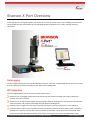
User Manual: Branson X-Port Module Document Number: XPRT-UM-50 Print Date: April 2, 2013 Menu bar selection options are in boldface and are abbreviated as Menu | Selection. For example, File | New Form means select New Form from the File drop-down menu. Start menu selections are in boldface and are abbreviated as Start | Programs | InfinityQS | Documents. File and directory references are in italics, such as c:\pfp\samples\prdorder. Drop down choices, names of tables within database manager, charts, and project names are in italics. For example, Turning Center. Dialog box names and field names are in boldface. For example, in the Field Properties dialog box, double click Customer Last Name. Buttons appear in UPPER CASE and in boldface. For example, click OK Keystrokes appear in UPPER CASE. For example, press ENTER Notes and warnings appear in ruled boxes: Note: This is an example of a note. Characters you are required to enter into a field using the keyboard appear in Courier New. For example, in the data entry field, type MyData. Ribbon bar buttons, toolbar buttons and chart bar buttons are in boldface. For example, Drawing toolbar button. The information contained in this document is subject to change without notice and does not represent a commitment on the part of InfinityQS International, Inc. This manual and the software described herein are furnished under the terms of the accompanying license and non-disclosure agreement. The software may be copied only in accordance with the terms of the agreement. It is a violation of Federal law to copy this manual or software onto any medium except as specifically allowed in the license or non-disclosure agreement. Copyright © 2013 InfinityQS International, Inc. All rights reserved. InfinityQS, ProFicient, ProFicient on Demand, ProFicient InSight, InfinityQS GTS, InfinityQS MSA, and InfinityQS RTI are trademarks or registered trademarks of InfinityQS International, Inc. Microsoft, MS-DOS, Excel, Access, Word, Windows, Windows 95/98/Me/2000/XP and Windows NT are trademarks of Microsoft Corporation. Other brands and product names are trademarks of registered trademarks of their respective holders. Use of these marks does not constitute or indicate any endorsement, sponsorship, recommendation of, or any affiliation with, any of these companies. 2| Copyright © 2013 InfinityQS International, Inc. All rights reserved. www.infinityqs.com Table of Contents Branson X-Port Overview ...................................................................................5 Data Logging ........................................................................................................................................... 5 SPC Integration ....................................................................................................................................... 5 Understanding the Interface ..............................................................................6 Interface Overview .................................................................................................................................. 6 Interface Elements .................................................................................................................................. 6 Installing Branson X-Port ....................................................................................9 Licensing Branson X-Port ..................................................................................10 Configuring Branson Power Supply ..................................................................13 Configuring Branson 2000X Power Supply ............................................................................................ 13 Configuring Branson 2000 Power Supply .............................................................................................. 13 Opening and Closing Branson X-Port ...............................................................14 Opening Branson X-Port........................................................................................................................ 14 Minimizing Branson X-Port ................................................................................................................... 14 Closing Branson X-Port.......................................................................................................................... 14 Configuring Branson X-Port ..............................................................................16 Defining Branson X-Port Equipment Settings............................................................................................. 16 Establishing Connection ........................................................................................................................ 16 Troubleshooting Connection ................................................................................................................. 18 Defining Branson X-Port Welder Characteristics........................................................................................ 19 Logging Branson X-Port Data...................................................................................................................... 20 Understanding Data Logging ................................................................................................................ 20 Opening Logging File............................................................................................................................. 26 Enabling Data Logging .......................................................................................................................... 27 Using Branson X-Port .......................................................................................29 Starting Branson X-Port Data Collection .................................................................................................... 29 3| Copyright © 2013 InfinityQS International, Inc. All rights reserved. www.infinityqs.com Viewing Branson X-Port Characteristic Distribution .................................................................................. 29 Integrating Branson X-Port with ProFicient SPC......................................................................................... 30 Enabling SPC Sampling.......................................................................................................................... 30 Setting Data Source (DSN) .................................................................................................................... 31 Setting Part ........................................................................................................................................... 32 Setting Process ...................................................................................................................................... 33 Setting Sampling Period ........................................................................................................................ 34 Enabling Alarm Logging ........................................................................................................................ 34 Closing SPC Sampling Dialog Box .......................................................................................................... 35 Stopping Branson X-Port Data Collection................................................................................................... 35 4| Copyright © 2013 InfinityQS International, Inc. All rights reserved. www.infinityqs.com Branson X-Port Overview From a single location, you can use Branson X-Port to connect to one or more Branson 2000 and 2000X Power Supplies on the shop floor or in the global network. This allows you to track and correct issues in your welding process real-time, and it provides you with visual displays of critical welding attributes, equipment error codes, and other summary information. Data Logging You can configure Branson X-Port to log weld attributes and error codes into a tab-delimited text file, which can be used by other reporting and analytical software to drill down into the welding data. SPC Integration You can integrate Branson X-Port with ProFicient SPC, which means: Branson X-Port can highlight specification limit and warning limit violations through color-coding, notifying an operator of an alarm condition. Branson X-Port can upload data samples into the ProFicient database, allowing you to run ProFicient's real-time SPC charts and reports and compare new welding data with historical welding data. ProFicient SPC can trigger real-time alarms, and send notifications to specific individuals on certain violations. ProFicient SPC can require users to provide the cause and corrective action for these violations, which can then be grouped into a report to track the most common problems and solutions. This ensures action will be taken when alarms occur and the collected information can be used as a proactive tool for improving welder performance. 5| Copyright © 2013 InfinityQS International, Inc. All rights reserved. www.infinityqs.com Understanding the Interface Interface Overview Interface Elements Welder Profiles You can create a data collection profile for each Branson 2000 and 2000X Power Supply. By clicking on a tab, you can configure and monitor the data collection for that specific power supply. Characteristic Data In each row, you can view information about the selected characteristic, which will depend on whether you have enabled SPC Sampling. SPC Sampling Enabled. If SPC Sampling is enabled, Branson X-Port displays lower and upper specification limits, average value, last captured value, and color indicators about status of last captured value. 6| Copyright © 2013 InfinityQS International, Inc. All rights reserved. www.infinityqs.com SPC Sampling Disabled. If SPC Sampling is disabled, Branson X-Port displays minimum and maximum values, average value, and last captured values. Characteristic Data Layout Top of Bar: The numbers are the lower and upper specification limits or the minimum and maximum values. (For SPC Sampling) If the lower specification limit is not defined, Branson X-Port displays the minimum value. If the upper specification limit is not defined, Branson X-Port displays the maximum value. Bottom of Bar: The triangle pointers indicate the lower and upper specification limits or the minimum and maximum values, as well as the average value of the two. If a reported value violates a specification limit or a value, the corresponding triangle changes from black to red. Inside the Bar: The thick line inside the bar represents location within the range of the most recently collected value. Color of Bar: Depending on the status of the last value collected, the bar changes color: red indicates a specification limit or value violation, yellow indicates a warning limit violation (if warning limits are defined in ProFicient). Right of Bar: To the right of the bar, Branson X-Port displays the most recently collected value. Alarm Code Data On the right side of the window, Branson X-Port displays a list of all alarm codes received since data collection started. Each row in the list shows the Weld Cycle number that generated the alarm condition. Welder Activity Data At the bottom of the screen, Branson X-Port displays welder activity data since data collection started. 7| Copyright © 2013 InfinityQS International, Inc. All rights reserved. www.infinityqs.com Mode. Welder's mode of operation. Welds. Total number of welds acquired. Run Time. Total length of time the welder has run. Welds/Hour. Maximum welds per hour calculated from Welds and Run Time. Alarms. Total number of welding alarms. Last Weld Number. Weld cycle number submitted by equipment and time when last weld occurred. 8| Copyright © 2013 InfinityQS International, Inc. All rights reserved. www.infinityqs.com Installing Branson X-Port 1. On the server, locate the Branson X-Port setup file: CD. Insert the Branson X-Port installation CD. If the installation does not automatically start, double click the installation file from the CD. Download. From the Branson X-Port downloads site (http://www.infinityqs.com/branson), download the installation file and then double click the installation file. Note: Your InfinityQS representative will provide the Branson X-Port installation executable. 2. After double clicking the installation file, the Choose Setup Language prompt opens. 3. In the Choose Setup Language data field, click the drop-down list and then click the desired language. 4. When finished, click OK. The InfinityQS Branson X-Port – InstallShield Wizard Welcome screen opens. 5. In the Welcome screen, click Next. The wizard installs the Branson X-Port. 6. When finished, the wizard displays the finish screen. 7. Click Finish. The install wizard closes. 9| Copyright © 2013 InfinityQS International, Inc. All rights reserved. www.infinityqs.com Licensing Branson X-Port Using the following instructions, you can register your purchased copy for unrestricted use. Type the registration number included with your installation package. You can locate the registration number on the Branson X-Port CD jacket. 1. After installing, open Branson X-Port by doing the following: On the desktop, click the Branson X-Port link. On the workstation, click Start | Programs | InfinityQS | Branson | Branson X-Port. Branson X-Port opens, prompting you for registration information. Note: To manually open the Branson X-Port License Utility, click Start | Programs | InfinityQS | Shared | Utilities | License Utility. 2. In the Registration Information dialog box, type or verify your User Name and Company Name, and then click OK. The Registration dialog box opens. 3. In the Registration dialog box, click the Register Purchased Copy radio button, and then click OK. The Registration Number dialog box opens. 4. In the Registration Number dialog box, click in the data field and type your registration number. Note: Locate your registration number on your Branson X-Port CD case. 10| Copyright © 2013 InfinityQS International, Inc. All rights reserved. www.infinityqs.com Note: If you do not have your registration number, click the Request Support Online button. On the Licensing page, locate the Permanent Licenses section, click the link and then fill out and submit the form. 5. Click OK. The License Number dialog box opens. 6. In the License Number dialog box, click the www.infinityqs.com/license.html button. The User Information page opens. 7. In the User Information page, type the following: Your Name: Your Name Phone Number: Your Phone Number Email Address: Your E-mail Address Re-type Email Address: Retype Your E-mail Address 8. When finished, click the Submit Information button. The Application Information page opens. 9. In the Application Information page, type or verify the following: Access Code: Access Code from the CD jacket Registration #: Software Registration # (should be pre-filled) Installation #: Installation Number (should be pre-filled) 10. When finished, click the Get License Number button. The Application Information e-mail confirmation page opens. 11| Copyright © 2013 InfinityQS International, Inc. All rights reserved. www.infinityqs.com 11. In your mail box, locate the e-mail from InfinityQS Licensing Center, which includes the Registration #, Install #, and License #, and then return to the License Number dialog box. 12. In the License Number dialog box, click in the Product License No. data field and type your product license number. 13. Click OK. The License Number dialog box closes. 12| Copyright © 2013 InfinityQS International, Inc. All rights reserved. www.infinityqs.com Configuring Branson Power Supply Configuring Branson 2000X Power Supply 1. On the 2000X Power Supply touch screen, press the Main Menu button. The MAIN MENU screen opens. 2. In the MAIN MENU screen, press the System Configuration button. The SYSTEM CONFIGURATION screen opens. 3. In the SYSTEM CONFIGURATION screen, press the following: RS 232 Host and Save. 4. In the Welder Addr data field, press OFF. 5. When finished, save the changes, and then close the SYSTEM CONFIGURATION screen. Configuring Branson 2000 Power Supply 1. In the MAIN MENU screen, press the SYSTEM CONFIGURATION button. The SYSTEM CONFIGURATION screen opens. 2. In the SYSTEM CONFIGURATION screen, press the following: RS 232 Compuweld or Host and Enter. 3. In the Welder Addr data field, press OFF. 4. When finished, press ESC. 13| Copyright © 2013 InfinityQS International, Inc. All rights reserved. www.infinityqs.com Opening and Closing Branson X-Port Opening Branson X-Port 1. On the ProFicient computer, click Start | Programs | InfinityQS | Branson | Branson X-Port. 2. Branson X-Port opens. Note: If you haven't previously configured Branson X-Port, the Equipment Settings dialog box automatically opens. For instructions on using the Equipment Settings dialog box, see "Configuring Branson X-Port". Minimizing Branson X-Port 1. In the Branson X-Port menu bar, click File | Close Window. OR Click the X in the upper right hand corner of Branson X-Port. 2. Branson X-Port minimizes to the Windows task tray , allowing it to continue processing welding information. 3. To restore Branson X-Port, double click the minimized icon in the task tray. OR In the Windows task tray, right click the Branson X-Port icon , and then click Open. Branson X-Port opens. Closing Branson X-Port 1. In the Branson X-Port menu bar, click File | Shut Down. OR In the Windows task tray, right click the Branson X-Port icon , and then click Shut Down. 14| Copyright © 2013 InfinityQS International, Inc. All rights reserved. www.infinityqs.com 2. Branson X-Port closes. 15| Copyright © 2013 InfinityQS International, Inc. All rights reserved. www.infinityqs.com Configuring Branson X-Port Using this section, you can do the following: Defining Branson X-Port Equipment Settings Defining Branson X-Port Welder Characteristics Logging Branson X-Port Data Defining Branson X-Port Equipment Settings Establishing Connection Note: If the equipment settings have not been configured, the Equipment Settings dialog box automatically opens. To change existing equipment settings, click Configuration | Equipment Settings in the Branson X-Port menu bar. 1. Stop the data collection. For instructions on stopping the data collection, see "Stopping Branson X-Port Data Collection". 2. The Equipment Settings dialog box opens. 3. In the Name data field, type the equipment settings name. This name appears on the tab in Branson X-Port. 16| Copyright © 2013 InfinityQS International, Inc. All rights reserved. www.infinityqs.com 4. Under Communication Source, click the drop-down list and then click the desired connection method, Ethernet TCP/IP or Serial Port. Ethernet TCP/IP (2000X Power Supply) Serial Port (2000 Power Supply) In the IP Address data field, type the IP Address of the 2000X Power Supply. To get the IP Address, do one of the following: In the serial port drop-down lists (Port, Baud Rate, Parity, Data Bits, Stop Bits, and Flow Control), click the values for the workstation's RS232 output. Press the System Information button on the 2000X Power Supply's MAIN MENU screen, and then press the View IP Address button. OR Press the Window Setup button on the 2000X Power Supply's MAIN MENU screen, and then double click the Ethernet icon in the task tray near the clock. Using a null model cable, connect the workstation to the 2000 Power Supply. In the ID Port data field, type 4000. 5. To test the connection (IP address or serial port), click the Start button. Successful Connection. If the connection is successful, the Equipment Settings dialog box displays Connected in the status bar and displays weld information in the information box. Note: While connected and collecting test weld information, the Start button changes to a Stop button. To disconnect and stop collecting test weld information, click the Stop button. o To view the raw data output from the welder, click the Raw Data Output checkbox. o To copy the weld information in the information box onto the workstation's clipboard, click the Copy button. o To clear the weld information in the information box, click the Clear button. 17| Copyright © 2013 InfinityQS International, Inc. All rights reserved. www.infinityqs.com Unsuccessful Connection. If the connection is unsuccessful, the Equipment Settings dialog box displays the error code in the status bar (for example, 10060 – The attempt to connect timed out, 10061 – Connection is forcefully rejected, etc.). For instructions on troubleshooting the connection, see "Troubleshooting Connection". 6. Examine the results of the test connection. Troubleshooting Connection Using this section, you can verify the IP connection to the Branson 2000 or 2000X Power Supply. 1. On the Branson X-Port workstation, click Start | Programs | Accessories | Communications | HyperTerminal. The New Connection – HyperTerminal opens. 2. In the Connection Description dialog box, type the following: BransonTest and then click OK. The Connect To dialog box opens. 3. In the Connect To dialog box, click the Connect using drop-down, and then click TCP/IP (Winsock). The Connect To dialog box changes to allow entry of TCP/IP connection information. 4. In the Host address data field, type the IP Address of the Branson 2000X Power Supply. 5. In the Port number data field, type 4000. 18| Copyright © 2013 InfinityQS International, Inc. All rights reserved. www.infinityqs.com Note: The Host address and Port number is the same as the IP Address and the ID Port that you entered in the Equipment Settings dialog box above. 6. In the Connect To dialog box, click OK. If successful, the HyperTerminal session shows the data stream from the Branson 2000X Power Supply. If unsuccessful, please contact your IT department or Branson technical support for assistance with connecting to the Branson 2000X Power Supply. 7. In the BransonTest – HyperTerminal menu bar, click File | Exit. The HyperTerminal save prompt opens. 8. In the HyperTerminal save prompt, click No. The BransonTest – HyperTerminal closes. Defining Branson X-Port Welder Characteristics 1. Stop the data collection. For instructions on stopping the data collection, see "Stopping Branson X-Port Data Collection". 2. Click the desired welder tab. 19| Copyright © 2013 InfinityQS International, Inc. All rights reserved. www.infinityqs.com 3. Under Characteristics, click the drop-down list and then click the desired characteristic: Energy. Total energy applied to part during the weld, in joules. Peak Power. Maximum power draw during weld, in percent of peak power. Total Absolute. Distance from home position upper limit to end of weld, in inches. Total Collapse. Distance from trigger to end of hold, in inches. Velocity. Actuator speed before touching the part, in inches per second. Weld Collapse. Distance from trigger to end of weld, in inches. Weld Force. Force at end of weld, in pounds. Weld Time. Total time from trigger to end of weld, in seconds. 4. Repeat the above step, adding up to eight characteristics. 5. When finished, start the data collection. For instructions on starting the data collection, see "Starting Branson X-Port Data Collection". Logging Branson X-Port Data Understanding Data Logging Branson X-Port can record information about each weld performed, adding lines to the bottom of the logging file. To start logging data, you must enable data logging and also start data collection by clicking the Start button. If unable to write to the logging file, Branson X-Port records the error to the iibransonxport.log file, which is typically located in the ProFicient \Private folder. Below is an example of the logging file. Acquired Time Cycle Count Hour Total Cycle Time ... Weld Force Hold Force 0/00/0000 0:00:00 PM 00 ... 100 00 100 65536.15 Note that: 20| Copyright © 2013 InfinityQS International, Inc. All rights reserved. www.infinityqs.com The first row is the header, containing each column label in the logging file. Each weld is on a separate line, and the lines are separated with a carriage return (ASCII 13) and line feed (ASCII 10). Each attribute value in a row is separated with a tab (ASCII 9). Log File Details Below is a description of each column saved to the log file. Column Description Acquired Time The computer's time when the weld was performed. Cycle Count Sequential weld number. This number comes from the welder and is not reset by Branson X-Port. Hour Hour when the weld occurred. Minute Minute within the Hour when the weld occurred. Second Second within the Minute when the weld occurred. Year Year when the weld occurred. Month Month within the Year when the weld occurred. Day Day within the Month when the weld occurred. Weld Time Time from trigger to the end of weld in seconds. Energy Energy applied to the part in Joules. Distance Distance from the upper limit home position to the end of weld in inches. Weld Collapse Distance from trigger to the end of weld in inches. Total Collapse Distance from trigger to the end of hold in inches. Start Frequency Frequency of the power supply at the start of weld in Hertz. End Frequency Frequency of the power supply at the end of weld in Hertz. Frequency Change Delta between start and end frequency in Hertz. Frequency Minimum Minimum frequency of the power supply during a weld in Hertz. Frequency Maximum Maximum frequency of the power supply during a weld in Hertz. Velocity Speed of the actuator before touching the part in Inches per second. Trigger Distance Distance from upper limit home position to trigger in inches. Reject Part Alarms See Reject Alarm Values 21| Copyright © 2013 InfinityQS International, Inc. All rights reserved. www.infinityqs.com Column Description Suspect Part Alarms See Suspect Part Alarm Values No Cycle Alarms See No Cycle Alarm Values Overload Alarms See Overload Alarm Values Equipment Failure Alarms See Equipment Failure Alarm Values Cycle Modified Alarms See Cycle Modified Alarm Values Preset # Welder’s current preset number. Note Alarms See Note Alarms Values Amplitude A Step amplitude profiling start amplitude in percent. Amplitude B Step amplitude profiling end amplitude in percent. Weld Mode See Weld Mode Values PS Control Flags <undefined> Peak Power Maximum power draw during weld in percent. Weld Pressure Regulator pressure in PSI. Weld Force Force at end of weld in pounds. Hold Force Force at end of hold in pounds. Total Cycle Time Total elapsed time from the beginning to the end of a weld cycle. Reject Part Alarm Values In the data file the Reject Alarm value can represent one or more codes based on its bit-wise value. Bit Assignment Alarm Text Bit00 -R Energy Limit Bit01 +R Energy Limit Bit02 -R Pk Power Limit Bit03 +R Pk Power Limit Bit04 -R Col Dist Limit Bit05 +R Col Dist Limit Bit06 -R Abs Dist Limit Bit07 +R Abs Dist Limit Bit08 -R Trig Dist Limit Bit09 +R Trig Dist Limit Bit10 -R Weld Force Limit 22| Copyright © 2013 InfinityQS International, Inc. All rights reserved. www.infinityqs.com Bit Assignment Alarm Text Bit11 +R Weld Force Limit Bit12 -R Time Limit Bit13 +R Time Limit Bit14-16 <undefined> Bit17 LL Not Reached Bit18-31 <undefined> Suspect Part Alarms Values In the data file the Suspect Alarm value can represent one or more codes based on its bit-wise value. Bit Assignment Alarm Text Bit00 -S Energy Limit Bit01 +S Energy Limit Bit02 -S Pk Power Limit Bit03 +S Pk Power Limit Bit04 -S Col Dist Limit Bit05 +S Col Dist Limit Bit06 -S Abs Dist Limit Bit07 +S Abs Dist Limit Bit08 -S Trig Dist Limit Bit09 +S Trig Dist Limit Bit10 -S Weld Force Limit Bit11 +S Weld Force Limit Bit12 -S Time Limit Bit13 +S Time Limit Bit14-31 <undefined> No Cycle Alarms In the data file the No Cycle Alarm value can represent one or more codes based on its bit-wise value. Bit Assignment Alarm Text Bit00 Upper Limit Timeout Bit01 <undefined> Bit02 Trigger Before Pretrigger Bit03 Trigger Timeout Bit04 <undefined> Bit05 LLS abort before TRS 23| Copyright © 2013 InfinityQS International, Inc. All rights reserved. www.infinityqs.com Bit Assignment Alarm Text Bit06 External Cycle Abort Bit07 Missing Part Abort Bit08 Abs Before Trigger Bit09 Amp Step before Trigger Bit10 F Step before Trigger Bit11 Ground Detect Cutoff Bit12-31 <undefined> Overload Alarms Values In the data file the Overload Alarm value can represent one or more codes based on its bit-wise value. Bit Assignment Alarm Text Bit00 Test Overload Bit01 Pretrigger Overload Bit02 Seek Overload Bit03 Power Supply Overload Bit04 Cont Power Limit Bit05 Afterburst Overload Bit06 Pre-Weld Seek Overload Bit07 Post Weld Seek Overload Bit08-31 <undefined> Equipment Failure Alarms Values In the data file the Equipment Failure Alarm value can represent one or more codes based on its bit-wise value. Bit Assignment Alarm Text Bit00 Encoder Failed Bit01 Upper Limit Switch Bit02 Upper Limit Switch Bit03 Door Sw Fail Bit04 <undefined> Bit05 Solenoid Drive Fail Bit06 Thermal Overload Bit07 Preset Data/BBR Bit08 Horn Return Timeout Bit09 Actuator NovRam Bit10 P/S NovRam 24| Copyright © 2013 InfinityQS International, Inc. All rights reserved. www.infinityqs.com Bit Assignment Alarm Text Bit11 Start Sw Time Bit12 MPS Switch Failed Bit13 Wrong Actuator Bit14 Ultrasonic P/S Bit15 Printer Buffer Full Bit16 Start Switch Closed Bit17 Pretrigger Timeout Bit18 <undefined> Bit19 Recalibrate Actuator Bit20 Act Clear Function Bit21 Stack Bit22 Start Switches Lost Bit23 Actuator Type Bit24 Sys. Pres. Incorrect Bit25-31 <undefined> Cycle Modified Alarms Values In the data file the Cycle Modified Alarm value can represent one or more codes based on its bit-wise value. Bit Assignment Alarm Text Bit00 Trigger Lost in Hold Bit01 Ground Detect Cutoff Bit02 Maximum Timeout Bit03 No Amplitude Step Bit04 No Force Step Bit05 No Amplitude Step Bit06 No Force Step Bit07 No Amplitude Step Bit08 No Amplitude Step Bit09 No Force Step Bit10 No Amplitude Step Bit11 No Amplitude Step Bit12 No Force Step Bit13 Trigger Lost in Weld Bit14 External Cycle Abort 25| Copyright © 2013 InfinityQS International, Inc. All rights reserved. www.infinityqs.com Bit Assignment Alarm Text Bit15 Amp B Not Reached Bit16 Amp Not Reached Bit17 Amp A Not Reached Bit18 Amp B Not Reached Bit19 Amp Exceeded Bit20 Energy Not Reached Bit21 Trigger > End Force Bit22 No Force Step Bit23-31 <undefined> Note Alarms Values In the data file the Note Alarm value can represent one or more codes based on its bit-wise value. Bit Assignment Alarm Text Bit00 Act Clr Not Reached Bit01 Max Energy Reached Bit02 Printer Buffer 80% Bit03 Cont Power Limit Bit04 Peak Power Cutoff Bit05 Absolute Cutoff Bit06 Time Extended Bit07 Act Recal Suggested Bit08 Collapse Cutoff Bit09 Act Clr Not Reached Bit10-31 <undefined> Opening Logging File 1. Stop the data collection. For instructions on stopping the data collection, see "Stopping Branson X-Port Data Collection". 2. Using a text editor, locate and open the logging file. Note: InfinityQS recommends that you create a copy of the logging file and open the copy, so you will not interrupt the weld information logging. If you open the logging file while Branson X-Port is running, Branson X-Port will continue to run normally, but will not log weld information. 3. When finished, start the data collection. For instructions on starting the data collection, see "Starting Branson X-Port Data Collection". 26| Copyright © 2013 InfinityQS International, Inc. All rights reserved. www.infinityqs.com Enabling Data Logging 1. Stop the data collection. For instructions on stopping the data collection, see "Stopping Branson X-Port Data Collection". 2. In the Branson X-Port menu bar, click Configuration | Data Logging. The Data Logging dialog box opens. 3. In the Data Logging dialog box, click the Enabled checkbox. 4. Under Data File, click the ellipsis button (…). The Data Logging browse dialog box opens. 5. In the Data Logging browse dialog box, browse to the desired location of the data logging file. 6. In the File name data field, type the name of the logging file. For example, type DataLogging.txt. 7. In the Data Logging browse dialog box, click the Open button. The Data Logging browse dialog box closes. Note: Branson X-Port displays the size of the logging file under Data File in the Data Logging dialog box. 27| Copyright © 2013 InfinityQS International, Inc. All rights reserved. www.infinityqs.com 8. In the Data Logging dialog box, click OK. The Data Logging dialog box closes. 9. When finished, start the data collection. For instructions on starting the data collection, see "Starting Branson X-Port Data Collection". 28| Copyright © 2013 InfinityQS International, Inc. All rights reserved. www.infinityqs.com Using Branson X-Port Using this section, you can do the following: Starting Branson X-Port Data Collection Viewing Branson X-Port Characteristic Distribution Integrating Branson X-Port with ProFicient SPC Stopping Branson X-Port Data Collection Starting Branson X-Port Data Collection 1. In Branson X-Port, click the Start button. 2. Branson X-Port collects characteristic data and welder activity data. Note: Every time you click the Start button, Branson X-Port resets alarm codes and welder activity data. Viewing Branson X-Port Characteristic Distribution During data collection, you can view the value distribution for a characteristic, as well as other statistics, since data collection started in the current welder profile. 1. To view the distribution, click the ellipsis button (…) in the desired characteristic row. 2. The characteristic distribution dialog box opens. 29| Copyright © 2013 InfinityQS International, Inc. All rights reserved. www.infinityqs.com 3. When finished, click the Close button. The characteristic distribution dialog box closes. Integrating Branson X-Port with ProFicient SPC By integrating with ProFicient SPC, Branson X-Port enhances its screen display with specification limits and color-coding (red for specification limit violations, yellow for a warning limit violations), and also Branson X-Port can compile weld information into data samples and save them into the ProFicient SPC system. Note: InfinityQS recommends that you involve members of the quality team when configuring an SPC sampling strategy. For more information about ProFicient SPC, please contact your InfinityQS representative, refer to the ProFicient reference material, or browse to the http://www.infinityqs.com. Enabling SPC Sampling 1. Stop the data collection. For instructions on stopping the data collection, see "Stopping Branson X-Port Data Collection". 2. In the Branson X-Port menu bar, click Configuration | SPC Sampling. Note: If the Select InfinityQS Data Source dialog box opens, click the ProFicient Data Source Name, click OK. In the user sign in dialog box, type your ProFicient user name and password, and click OK. The SPC Sampling dialog box opens. 30| Copyright © 2013 InfinityQS International, Inc. All rights reserved. www.infinityqs.com 3. In the SPC Sampling dialog box, click the Enabled checkbox. Setting Data Source (DSN) 1. In the SPC Sampling dialog box, locate the Database section. 2. In Data Source, click the ellipsis button (…). The Select InfinityQS Data Source dialog box opens. 31| Copyright © 2013 InfinityQS International, Inc. All rights reserved. www.infinityqs.com 3. In the list of available DSNs, click the ProFicient Data Source Name, and then click OK. The user sign in dialog box opens. 4. In the user sign in dialog box, type the following: Sign In Name. Type your ProFicient user name. Password. Type your ProFicient password. 5. When finished, click OK. The Select InfinityQS Data Source dialog box closes. Setting Part When using SPC sampling, you must define the part being welded. When Branson X-Port saves results to InfinityQS ProFicient SPC, the values are associated with the part name, allowing you to group similar weld data based on the part in ProFicient SPC. 1. In the SPC Sampling dialog box, locate the Database section. 2. In Part, click the ellipsis button (…). The Part Selection dialog box opens. 32| Copyright © 2013 InfinityQS International, Inc. All rights reserved. www.infinityqs.com 3. In the Part Selection dialog box opens, select the desired group and part in the database by doing the following: In the Group data field, click the drop-down list and then click the desired group. In the Item data field, click the desired part. 4. When finished, click OK. The Part Selection dialog box closes. 5. To allow users to change parts from the Branson X-Port screen, click the Reselect Part checkbox. Note: Use the Reselect Part option when you run multiple parts on the same welder. Setting Process When using SPC sampling, you must define the process being used. When Branson X-Port saves results to InfinityQS ProFicient SPC, the values are associated with the process name (for example, Welder #1, Welder #2, etc.), allowing you to create different control charts within ProFicient SPC to monitor the processes. 1. In the SPC Sampling dialog box, locate the Database section. 2. In Process, click the ellipsis button (…). The Process Selection dialog box opens. 3. In the Process Selection dialog box opens, select the desired group and process in the database by doing the following: 33| Copyright © 2013 InfinityQS International, Inc. All rights reserved. www.infinityqs.com In the Group data field, click the drop-down list and then click the desired group. In the Item data field, click the desired process. 4. When finished, click OK. The Process Selection dialog box closes. Setting Sampling Period From a statistical standpoint, you only need to collect periodic samples from the continuous data stream, which reduces the quantity of information the quality team must review while providing adequate detail on the current state of the process (welder). Please consult with your quality team to determine your optimum collection strategy. 1. In the SPC Sampling dialog box, locate the Sampling section. 2. In Period, type the length of the interval in the data field, click the drop-down list and then click the units (Seconds, Minutes, Hours). This defines how frequently Branson X-Port stores quality samples. 3. In Subgroup Size, type the maximum number of successive weld values that Branson X-Port will compile from the continuous data stream. 4. To only save weld attribute characteristics that are displayed, click the Save only characteristics that are displayed in the main screen radio button. To save all weld attribute characteristics, click the Save all characteristics radio button. Enabling Alarm Logging If you enable alarm logging, Branson X-Port will save alarm notifications reported by the welder to ProFicient SPC. 1. In the SPC Sampling dialog box, locate the Sampling section. 2. Under Alarm Logging, click the Enabled checkbox. 3. Under the Enabled checkbox, click the checkboxes of the alarm categories you want to store. 34| Copyright © 2013 InfinityQS International, Inc. All rights reserved. www.infinityqs.com Closing SPC Sampling Dialog Box 1. In the SPC Sampling dialog box, click OK. 2. The SPC Sampling dialog box closes. Stopping Branson X-Port Data Collection 1. In Branson X-Port, click the Stop button. 2. Branson X-Port stops collecting characteristic data and welder activity data. 35| Copyright © 2013 InfinityQS International, Inc. All rights reserved. www.infinityqs.com