1
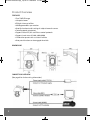
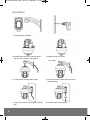
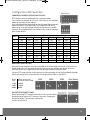
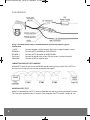
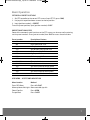
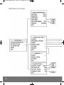
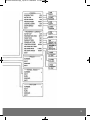
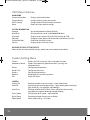
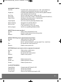
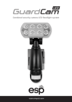
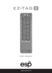
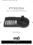
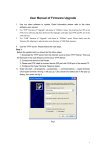
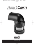
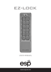
HDVCPTZ Manual.qxp_Layout 2 13/05/2015 12:10 Page 1
H DV C P T Z
T R U E H D 7 2 0 P PA N , T I LT & Z O O M C C T V C A M E R A
USER MANUAL
w w w. e s p u k .com
HDVCPTZ Manual.qxp_Layout 2 13/05/2015 12:10 Page 2
Product Overview
FEATURES
• True 720P HD image
• 10x optical zoom
• IR Night vision up to 50m
• 360 degree endless pan rotation
• Auto flip function to aid tracking of subjects beneath camera
• Control protocol auto-detect
• Supports Pelco D/P, Hik and Dahua control protocols
• Supports baud rates of 2400, 4800, 9600
• 220 location presets with scan/tour facilities
• Auto patrol function can be engaged when idle
DIMENSIONS
CONNECTION OVERVIEW
(See page 6 for further wiring information)
2
HDVCPTZ Manual.qxp_Layout 2 13/05/2015 12:10 Page 3
Pre-Installation Guidance
SITING YOUR PTZ CAMERA
Do not install your PTZ camera in any of the following locations:
• In areas where humidity reaches >90%
• Near a boiler flue or air conditioning outlet.
• In environments high in smoke or dust.
Avoid directing the camera towards very strong light sources such as the sun. You should also
avoid high output light sources such as floodlighting. Prolonged exposure to strong light
sources damage the camera’s image sensor resulting in “bleached” colours.
ILLUMINATION
Multiple light sources from different directions will always produce better results than relying
only on the IR night vision, especially when trying to read vehicle number plates in dark
conditions.
If IR light is sourced from the same direction as the camera, it is reflected directly back at the
camera causing the number plate to appear as if illuminated/overexposed. Adequate ambient
light sourced from different directions will eliminate this. This applies to all cameras with
built-in IR.
POWER SUPPLY AND CABLING
Recommended cable types based on a standard installation (200M max cable run)
Control cable – Shielded control cable, 0.5mm (24AWG).
Video cable – RG59 <120M, CT100 or higher recommended for >120M
Power cable – Twin core minimum 0.2mm or higher
Please ensure all cabling is kept at least 300mm from main/high voltage cabling to avoid
interference.
Multiple PTZ cameras operated from the same controller must be wired in parallel in a “daisychain” layout. For more information see page 6.
MAINTENANCE
Be aware that as PTZ cameras contain moving parts, they are subject to more wear and tear
than traditional fixed cameras.
Ensure that the lens is periodically cleaned as dust and dirt can cause the auto focus to
function incorrectly.
Use a damp cloth to clean the lens, do not use liquids or chemicals of any sort.
3
HDVCPTZ Manual.qxp_Layout 2 13/05/2015 12:10 Page 4
Installation
4
1. Mark out the holes for the 4 fixing screws
using template provided
2. Drill holes and insert rawl plugs
3. Remove cover to access address/baud
rate/resistor switches (see page 5)
4. Replace cover and screw
5. Thread cables through the bracket
6. Insert M4 screws into bracket to secure
dome housing
7. Insert fixing screws and secure bracket to
wall
8. Connect cables (see page 6)
M4 SCREW
HDVCPTZ Manual.qxp_Layout 2 13/05/2015 12:10 Page 5
Configuration DIP Switches
SWITCH SW1
CAMERA ID/ ADDRESS SETUP (SWITCH SW1)
PTZ cameras must be addressed with a unique number.
This number can be from 0-255 and is set in binary, use the table
below to manually set the address.
Visit http://www.binaryhexconverter.com for more help to convert
decimal to binary. Once the camera is installed and the ID has
been set up, it can be changed without having to access the DIP
switches. It can be done from the camera menu system, see page
6 for further details.
Address
1
2
3
4
5
6
7
8
9
10
SW1-1
On
Off
On
Off
On
Off
On
Off
On
Off
SW1-2
Off
On
On
Off
Off
On
On
Off
Off
On
Switch SW1 Setup
SW1-3 SW1-4 SW1-5
Off
Off
Off
Off
Off
Off
Off
Off
Off
On
Off
Off
On
Off
Off
On
Off
Off
On
Off
Off
Off
On
Off
Off
On
Off
Off
On
Off
SWITCH SW2
SW1-6
Off
Off
Off
Off
Off
Off
Off
Off
Off
Off
SW1-7
Off
Off
Off
Off
Off
Off
Off
Off
Off
Off
SW1-8
Off
Off
Off
Off
Off
Off
Off
Off
Off
Off
BAUD RATE (SWITCH SW2)
All cameras operated from the same controller must all be configured to the same baud rate.
Lower baud rates will see fewer data errors and can be transmitted over longer distances
than high baud rates. Higher baud rates will be more responsive to user input.
Set your PTZ camera to the same baud rate as your controller, or use the Auto Detect function
which will configure this automatically. Set using switches SW2-1 and SW2-2.
Baud
rate
2400
4800
9600
Max transmission
distance (.5mm cable)
1800M
1200M
800M
EOL RESISTOR (SWITCH SW2)
When connecting PTZ cameras, the built in 120 resistor should
be connected on the last PTZ camera in the chain. See page 6
for further details. The resistor is connected
via DIP switch SW2-4.
5
HDVCPTZ Manual.qxp_Layout 2 13/05/2015 12:10 Page 6
Connections
Using a screened control cable is recommended for maximum protection against
interference.
12V/DC
Connect to power supply, connect 230V mains supply to power supply
RS485A(+)
Connect to PTZ controller (or DVR) RS485A+
RS485B(-)
Connect to PTZ Controller (or DVR) RS485BEarth wire
Connect to control cable screen. Ensure screen is earthed correctly
Video/BNC
Connect to DVR or monitor input
CONNECTING MULTIPLE PTZ CAMERAS
Multiple PTZ cameras must have the RS485 control cable wired in parallel. The last PTZ on
the chain must have the 120 resistor connected (see page 5).
POWER ON SELF-TEST
When first powered up, the PTZ camera will perform the self-test, testing all motor functions.
This test takes approximately 12 seconds. Once complete, the PTZ camera is ready for use.
6
HDVCPTZ Manual.qxp_Layout 2 13/05/2015 12:10 Page 7
Basic Operation
SET/RECALL PRESET POSITIONS
1. Set PTZ controller to the correct PTZ camera (input PTZ ID, press CAM)
2. Use joystick to position/zoom camera to chosen position
3. Input (position number), + PRESET
To recall a preset position, input (position number) +SHOT
PRESET FUNCTION ACCESS
Some of the commonly used functions on the PTZ camera can be accessed by entering
certain preset numbers. Press (preset number) then SHOT to access these functions.
Preset number
95
98
99
221
222
223
224
225
231-238
241-244
251
252
253
254
Description of feature
Access main menu
High speed auto-scan
Low speed auto-scan
Set position A of A-B line scan
Set position B of A-B line scan
High speed A-B scan
Medium speed A-B scan
Low speed A-B scan
Run patrol 1-8
Run mode scan 1-4
Set manual control to high speed
Set manual control to medium speed
Set manual control to low speed
Run motor calibration
OSD MENU – ACCESS AND NAVIGATION
Menu function
Enter OSD Menu
Move up/down/left/right
Select/Confirm
Escape/Back
Method
Press 95+SHOT
Move controller joystick
Press OPEN
Press CLOSE
7
HDVCPTZ Manual.qxp_Layout 2 13/05/2015 12:10 Page 8
OSD Menu Overview
8
HDVCPTZ Manual.qxp_Layout 2 13/05/2015 12:10 Page 9
9
HDVCPTZ Manual.qxp_Layout 2 13/05/2015 12:10 Page 10
OSD Menu Features
MAIN MENU
System Information
System Setting
IR LED Setting
Reset
Display system information
Configuration of system parameters
Configuration of IR illumination parameters
Revert to factory default settings
SYSTEM INFORMATION
Protocol
Baud Rate
Hard Addr
Soft Addr
Enable Soft Addr
Version
Set control protocol to Pelco/Hik/Auto
Set control baud rate to 2400/4800/9600/Auto
Display current address/ID set by DIP switches (0-255)
Configure a new address/ID to override Hard Address (0-255)
Enable the Soft Addr function
Display current firmware version
RECOVER FACTORY SETTING (RESET)
Select to load all factory default settings, power the camera down to take effect.
System Setting Menu
Camera
Movement Control
Preset
Patrol Track
Pattern
Remove
Exit
CAMERA
Screen Tips
Auto ICR
Auto Focus
Focus Speed
Digital Zoom
Zoom Speed
10
Options for OSD screen tips, focus and zoom functions
Options for movement speed, orientation, scanning and
movement limits
Configure preset positions
Configure patrol tracks
Configure patrol patterns
Remove presets, patrols or patterns
Leave OSD menu
Enable or disable screen tips and on-screen information
Enable high light level compensation – helps reduce glare from bright
light sources e.g. car headlight and floodlight
Enable or disable the AF feature. Focus will be entirely manually
controlled, only recommended for troubleshooting
Configuration of AF speed – high/med/low
Enable digital zoom feature (not available)
Zoom speed setting – fast/slow
HDVCPTZ Manual.qxp_Layout 2 13/05/2015 12:10 Page 11
MOVEMENT CONTROL
Auto Flip
Proportion
Park Time
Park Action
Power Action
Control Speed
AB Scan Setting
AB Scan Path
AB Scan Speed
Enable/disable auto flip (camera turns 180° when following a
subject passing underneath the camera, to aid tracking)
Enable/disable proportion pan (camera control speed is lowered
when zoomed in to aid tracking)
Set park time (idle time) in seconds (0-255)
Set park action when camera is idle (Preset/Pattern/Patrol/Scan)
Set power action when camera is powered up
(Preset/Pattern/Patrol/Scan)
Set camera control speed (High/Medium/Low)
Setup points A and B for AB Scan
Set AB scan path (I-Arc/O-Arc)
I-Arc= front facing, O-Arc= rear facing
Set AB scan speed (High/Medium/Low)
PRESET (Preset camera positions)
Number
Select preset to be edited (0-220)
Edit
Position camera/zoom to set preset position
Remove
Delete current preset
PATROL TRACK (A group of sequenced preset positions)
Number
Select patrol track to be edited
Edit
Create or edit a patrol track,
Preset = preset no, Speed = panning speed, Time = dwell time
Run
Run preview of current patrol track
Remove
Delete current patrol track
PATTERN (Records user input to mimic a sequence of movement)
Number
Select pattern to edit/create
Edit
Create or edit pattern
Run
Run preview of current pattern
Remove
Delete current pattern
REMOVE
Preset
Patrol Track
Pattern
Delete all preset data
Delete all patrol track data
Delete all pattern data
IR LED SETTING MENU
Control Mode
LED ON Level
LED Off Level
Current level
Control mode of IR (Auto/On/Off)
Set LED on threshold
Set LED off threshold
Show current ambient light level (0-255)
11
HDVCPTZ Manual.qxp_Layout 2 13/05/2015 12:10 Page 12
Technical Specifications
Rated Voltage
Max current
IR effective distance
Protection
Pan rotation
Speed
Working conditions
12V DC
1.25A
50M
IP66
360° Endless rotation
Pan 0.6-200°/s Tilt 3.5-30°/s
-10°C - +50°C
Elite Security Products
Unit 7, Target Park, Shawbank Rd
Lakeside, Redditch B98 8YN
Telephone: 01527 51 51 50
Fax: 01527 51 51 43
email: [email protected]
w w w. e s p u k .com