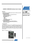
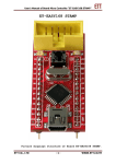
1
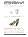
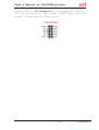
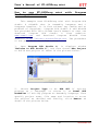
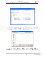
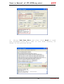
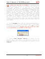
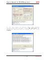
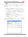
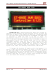
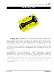
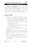
User's Manual of ET-AVRProg mini ET-AVRProg mini ET-AVRProg mini is the board that is designed to download HEX File into AVR Microcontroller of ATMEL through PORT ISP. It is compatible with Program AvrProg, AvrOspll, CodeVision, avrdude or other programs that support Protocol AVR910. Technical Specifications of ET-AVRProg mini 1. Program data through PORT ISP and be able to read, write, erase and protect data from reading 2. Be compatible with Target Board that uses 2.5V5.5V Power Supply 3. Communicate through PORT USB 4. Has Signal CLOCK to edit Fuse Bits if choosing Fuse Bits of Signal CLOCK wrongly. 5. Has LED to display operating status of USB, STATUS 6. Use standard ISP 10PIN Connector that is compatible with AVR Boards of ETT or other boards that have the standard 10PIN Connector such as ETAVR STAMP ATMEGA64/128, ET-BASE AVR, ET-Easy168 STAMP and etc. Moreover, there is Connector CONVERT that converts connector from ISP 10PIN Connector into ISP 6PIN Connector, so it is compatible with other AVR Boards. 7. Be compatible with programs that support Protocol AVR910 such as AvrProg, AvrOspll, CodeVision, or avrdude. 8. Support Windows 98, me, 2000, XP, Vista Document by OpenOffice.org 3 -1- www.etteam.com User's Manual of ET-AVRProg mini AVR Numbers that are programmable with Program AvrProg are: AT90S1200, AT90S2313, AT90S2323, AT90S2333, AT90S2343, AT90S4414, AT90S4433, AT90S4434, AT90S8515, AT90S8535, ATmega103, ATmega128, ATmega16, ATmega161, ATmega163, ATmega169, ATmega32, ATmega64, ATmega8, ATmega8515, ATmega8535, ATtiny10, ATtiny12, ATtiny15, ATtiny26 AVR Numbers that are programmable with Program AvrOspll are: AT90CAN128, AT90CAN32, AT90CAN64, AT90PWM2, AT90PWM216, AT90PWM2B, AT90PWM3, AT90PWM316, AT90PWM3B AT90S1200, AT90S2313, AT90S2323, AT90S2343, AT90S4414, AT90S4433, AT90S4434, AT90S8515, AT90S8515, AT90S8535, AT90SUSB1286, AT90SUSB1287, AT90SUSB162, AT90SUSB646, AT90SUSB647, AT90SUSB82, ATmega103, ATmega128, ATmega1280, ATmega1281, ATmega16, ATmega161, ATmega162, ATmega163, ATmega164P, ATmega165, ATmega165P, ATmega168, ATmega168P, ATmega169, ATmega169P, ATmega16HVA, ATmega2560, ATmega2561, ATmega32, ATmega323, ATmega234P, ATmega235, ATmega3250, ATmega2350P, ATmega325P, ATmega328P, ATmega329, ATmega3290, ATmega3290P, ATmega329P, ATmega406, ATmega48, ATmega48P, ATmega64, ATmega640, ATmega644, ATmega644P, ATmega645, Atmega6450, ATmega649, ATmega6490, ATmega8, ATmega8515, ATmega8535, ATmega88, ATmega88P, ATtiny11, ATtiny12, ATtiny13, ATtiny15, ATtiny22, ATtiny2313, ATtiny24, ATtiny25, ATtiny26, ATtiny261, ATtiny28, ATtiny43U, ATtiny44, ATtiny45, ATtiny461, ATtiny48, ATtiny84, ATtiny85, ATtiny861 AVR Numbers that are programmable with Program CodeVisionAVR are: ATtiny13, ATtiny22, ATtiny22L, ATtiny2313, ATtiny2313V, ATtiny24, ATtiny25, ATtiny26, ATtiny26L, ATtiny261, ATtiny261V, ATtiny44, ATtiny45, ATtiny461, ATtiny461V, ATtiny48, ATtiny48V, ATtiny84, ATtiny85, ATtiny861, ATtiny861V, ATtiny88, ATtiny88V, Document by OpenOffice.org 3 -2- www.etteam.com User's Manual of ET-AVRProg mini AT90S2343, AT90LS2343, AT90S4414, AT90S4433, AT90LS4433, AT90S4434, AT90LS4434, AT90S8515, AT90S8535, AT90LS8535, AT90CAN128, AT90CAN32, AT90CAN64, AT90PWM2, AT90PWM2B, AT90PWM216, AT90PWM3, AT90PWM3B, AT90PWM316, AT90USB1286, AT90USB1287, AT90USB162, AT90USB646, AT90USB647, AT90USB82, ATmega103, ATmega130L, ATmega128, ATmega128L, ATmega1280, ATmega1280V, ATmega1281, ATmega1281V, ATmega1284P, ATmega16, ATmega16L, ATmega161, ATmega161L, ATmega162, ATmega162L, ATmega162U, ATmega162V, ATmega163, ATmega163L, ATmega164, ATmega164V, ATmega164P, ATmega164PV, ATmega165, ATmega165V, ATmega168, ATmega168V, ATmega168P, ATmega168PV, ATmega169, ATmega169L, ATmega2560, ATmega2560V, ATmega2561, ATmega2561V, ATmega32, ATmega32L, ATmega232, ATmega323L, ATmega324, ATmega324V, ATmega324P, ATmega324PV, ATmega325, ATmega325V, ATmega3250, ATmega3250V, ATmega325P, ATmega325PV, ATmega3250P, ATmega3250PV, ATmega328P, ATmega328PV, ATmega329, ATmega329V, ATmega3290, ATmega3290V, ATmega329P, ATmega329PV, ATmega3290P, ATmega3290PV, ATmega48, ATmega48V, ATmega48P, ATmega48PV, ATmega603, ATmega603L, ATmega64, ATmega64L, ATmega640, ATmega640V, ATmega644, ATmega644V, ATmega644P, ATmega644PV, ATmega645, ATmega645V, ATmega6450, ATmega6450V, ATmega649, ATmega649V, ATmega6490, ATmega6490V, ATmega8, ATmega8L, ATmega8515, ATmega8515L, ATmega8535, ATmega8535L, ATmega88, ATmega88V, ATmega88P, ATmega88PV Document by OpenOffice.org 3 -3- www.etteam.com User's Manual of ET-AVRProg mini How to install Driver of ET-AVRProg mini 1. Interface ET-AVRProg mini with computer through PORT USB without interfacing with any Target Board, and then windows found new Hardware as shown in the picture below. 2. It displays window “Found New Hardware choose “Install from a list or specific (Advanced)” and then click Next. Wizard”, location 3. Choose values as shown in the picture below, click Browse to specify location of Driver and then click OK. Document by OpenOffice.org 3 -4- www.etteam.com User's Manual of ET-AVRProg mini 4. Click Next when user has already set all values successfully, and then windows searches Hardware to install Driver. Document by OpenOffice.org 3 -5- www.etteam.com User's Manual of ET-AVRProg mini 5. Click Finish when the window told user that the software has already been installed; in this case, LED that displays operating status of USB is ON, it means that the part of USB starts running. Document by OpenOffice.org 3 -6- www.etteam.com User's Manual of ET-AVRProg mini 6. Just a moment, the Driver builds alike Serial Port and there is window to install Driver of USB Serial Port as shown in the picture below; in this case, user should choose the values as same as the values in the previous step and then click Next. 7. Choose location of Driver; normally, it can remember the old value, so user can click Next instantly. Windows searches Hardware to install Driver. Document by OpenOffice.org 3 -7- www.etteam.com User's Manual of ET-AVRProg mini 8. Click Finish when window told that it has already installed successfully. 9. User can check the Driver installation of ETAVRProg mini whether it is complete or not; click Menu “Control Panel → System”, choose Tab Hardware and then choose Device Manager; in this case, the item of Hardware USB Serial Port is added as shown in the picture below. Document by OpenOffice.org 3 -8- www.etteam.com User's Manual of ET-AVRProg mini 10. Double-click USB Serial Port in the part of Ports(COM&LPT), it displays windows Properties as shown in the picture below; in this case, choose Port Setting and then click Advanced… 11. Change COM Port Number; if using Program AvrProg(AVR Studio), it only supports COM1-COM4; on the other hand, if using Program AvrOspll or CodeVision, it is able to set the COM PORT Number more than COM4. Moreover, it sets Receive(Bytes) to be 256, sets Transmit(Bytes) to be 128, and then sets Latency Timer (msec) to be 1 as shown in the picture below. Next, click OK to confirm the change and then restart computer or scan new Hardware again. Document by OpenOffice.org 3 -9- www.etteam.com User's Manual of ET-AVRProg mini Document by OpenOffice.org 3 -10- www.etteam.com User's Manual of ET-AVRProg mini How to Connect Microcontroller ET-AVRProg mini with AVR Basically, there are 2 types of ISP Connector to program AVR Microcontroller; ISP 6 PIN and ISP 10 PIN as shown in the picture below. In this case, AVR Microcontroller of ETT uses ISP 10 PIN Connector. If user has Board that is under standard of ISP 6 PIN, can use it with ET-AVRProg mini instantly; in this case, it is used with ADAPTER ISP-10TO6 as shown in the picture below. It uses Cable MISO, MOSI, SCK, RST, VTG, and GND that must be interfaced with Pin ISP Interface of AVR; in this case, there is Power Supply for AVR Microcontroller Board separately, it is unable to use Power Supply from ET-AVRProg mini. If it uses Pin ISP to be Pin PORT, it needs to interface Resistor at least 10 Ohm before using as shown in the picture below. Otherwise, there is error in loading signal for programming. Document by OpenOffice.org 3 -11- www.etteam.com User's Manual of ET-AVRProg mini Example Circuit of AVR Microcontroller From the picture above, it is the example circuit of AVR No.ATMEGA16 that describes the application of ET-AVRProg mini. It uses ISP 10PIN Connector, so user can uses Pair Cable 10PIN to connect signal from ETDocument by OpenOffice.org 3 -12- www.etteam.com User's Manual of ET-AVRProg mini AVRProg mini to H1 Connector for programming instantly. The Pin position of Pair Cable 10PIN when see from bottom is displayed as shown below. Document by OpenOffice.org 3 -13- www.etteam.com User's Manual of ET-AVRProg mini How to use ET-AVRProg AvrProg (AVR Studio) mini with Program This example uses ET-AVRProg mini with Program AVR Studio 4 +WinAVR that is Assembly Language and C Language Complier. It is free without any charge and no problem of copyright. Program AVR Studio 4 and WinAVR are provided with this CD-ROM User's Manual or user can download Program AVR Studio 4 from website: www.atmel.com and download Program WinAVR from website: http://winavr.sourceforge.net. The procedure to use program is described below; 1. Open Program AVR Studio 4; it displays window “Welcome to AVR Studio 4”, and then choose New Project to build new project as shown in the picture below. 2. Choose Project Type to be AVR GCC if writing program as C Language; or choose it as Atmel AVR Assembler if writing program as Assembly Language. Then specify project name, file name and location to store the project as desired and finally, click Next>> as shown in the picture below. Document by OpenOffice.org 3 -14- www.etteam.com User's Manual of ET-AVRProg mini 3. Choose Debug platform as AVR Simulator in the case of imitating operation of the program that is written by software; choose Device as Atmega16 that is the reference number for the application; and finally click Finish as shown in the picture below. 4. It displays blank window for writing program as shown in the picture below. Document by OpenOffice.org 3 -15- www.etteam.com User's Manual of ET-AVRProg mini 5. Write program by C language as required; in this case, it is the example program of blinking light at PIN PB0 of Atmega16 with 1 second speed as shown in the example below. 6. After wrote program successfully, click Menu “Project → Configuration Options” as shown in the picture below; Document by OpenOffice.org 3 -16- www.etteam.com User's Manual of ET-AVRProg mini 7. It displays window “Project Options”; choose Device to be atmega16, and Frequency to be 8000000 hz as shown in the circuit. Next, choose value in the blank Create Hex File and finally click OK as shown in the picture below. 8. When set values completely, click Menu Build to compile program as shown in the picture below. Document by OpenOffice.org 3 -17- www.etteam.com User's Manual of ET-AVRProg mini 9. If the written program is correct according to the syntax, it displays message “Build succeeded” as shown in the picture below. On the other hand, if it is incorrect, it displays error message to warn user to edit and re-build the new one. 10. When everything is OK, next step is downloading HEX File into AVR Microcontroller, click Menu “Tools → AVR Prog” as shown in the picture below. Document by OpenOffice.org 3 -18- www.etteam.com User's Manual of ET-AVRProg mini 11. It displays window of Program AVRProg, set Device to be Atmega16 and then click Advanced as shown in the picture below. 12. If program is unable to connect with ET-AVRProg mini, it displays message as shown in the picture below, so user needs to check the connection between ET-AVRProg mini and computer again. The main cause may be occurred because of installing Driver incompletely; in this case, user can see LED that displays the operating status of ET-AVRProg mini to check whether it is ON or OFF. If it is ON, it is correct; on the other hand, if it is OFF, it has problem. Moreover, it maybe occurred because of choosing the COM Port Number incorrect, not in the range of COM1-COM4; in this case, Program Avrprog only supports COM1-COM4. 13. It displays picture below. Document by OpenOffice.org 3 window Advanced -19- as shown in the www.etteam.com User's Manual of ET-AVRProg mini From the picture above, it displays the Parameter value and Fuse Bits value of Atmega16 that is connected with ET-AVRProg mini, these values are set from factory. The source of Signal CLOCK is IntRCosc, Frequency 1 MHz that uses RC Oscillator 1MHz internal Microcontroller. In this case, the circuit uses Crystal Frequency 8 MHz, so it needs to edit Fuse Bits. 14. Set new Fuse Bite according to the circuit that are actually used as shown in the picture below; in this case, it sets Signal CLOCK to be External Crystal. Document by OpenOffice.org 3 -20- www.etteam.com User's Manual of ET-AVRProg mini NOTE: Always choose Fuse Bits as “SPI Enable”. If user does not choose this value, it makes user can not program through ISP anymore. The method to edit the incorrect Fuse Bits is to use the high voltage Programmer such as ALL11, SUPERPRO. Moreover, it is also important part, user has to choose the source of Signal CLOCK according to the actually used circuit; for example, if the circuit uses Oscillator to be the Signal CLOCK Generator but user choses External Signal CLOCK (ExtRCosc), it makes user can not program through ISP anymore. In this case, it needs to edit by the high voltage Programmer or ET-AVRProg mini that is described at the end of this User's Manual. So, be very careful to choose and set this Fuse Bits, user can see more detailed information regarding Fuse Bits from Data Sheet of each number. 15. Click Write after set all values successfully to write Fuse Bits value into Microcontroller as shown in the picture below, and then click Close to exit from this window. Advice: Write the Fuse Bits only one time, next time it is unnecessary to program this value again because it is still forever and is not deleted with the Document by OpenOffice.org 3 -21- www.etteam.com User's Manual of ET-AVRProg mini part of Program memory; so, user has to program the Fuse Bite carefully. 16. Choose HEX File that is complied; normally, it is in Folder default of the project that we built. Click Program. When programmed successfully, the LED at Pin PB0 is blinking at 1 second speed. 17. If user wants to protect data from reading (protect data from copying); click Advance, choose operating mode of Lock Bits as required and finally, click Write. Document by OpenOffice.org 3 -22- www.etteam.com User's Manual of ET-AVRProg mini Application of ET-AVRProg mini with Program CodeVisionAVR Program CodeVisionAVR is C Language Compiler of AVR Microcontroller that is widely popular because it is easy to use. However, this Compiler is not free. This example uses demo version of CodeVisionAVR that has limited size of Code program as 2 Kbyte. If user wants the full version or to try the program, please visit website: www.hpinfotech.com. This Program CodeVisionAVR is compatible with ET-AVRProg mini without opening other programs. The procedure of using this program is described below; 1. Open Program CodeVisionAVR and click Menu “File → New” as shown in the picture below. 2. Choose File Type as Source to build new C Language File and then click OK as shown in the picture below. Document by OpenOffice.org 3 -23- www.etteam.com User's Manual of ET-AVRProg mini 3. It displays window Editor for writing program, the example below is the program of blinking light at PB0. 4. Save the program that is written by C Language, choose Menu “File → Save”, specify file name and then click Save as shown in the picture below. 5. Go to Menu “File → New”, choose File Type as Project to build new project and then click OK as shown in the picture below. Document by OpenOffice.org 3 -24- www.etteam.com User's Manual of ET-AVRProg mini 6. Click No, if you do not need any assistance to build the project (CodeWizard) as shown in the picture below. 7. Specify the project name as required click Save as shown in the picture below. and then 8. Add C Language File that is written previously into the project, click Add as shown in the picture below. Document by OpenOffice.org 3 -25- www.etteam.com User's Manual of ET-AVRProg mini 9. Choose Tab Configuration Project and go to C Compiler; choose Chip as Atmega16 and Clock as 8.000000 MHz as show in the picture below. Document by OpenOffice.org 3 -26- www.etteam.com User's Manual of ET-AVRProg mini 10. Go to Tab After Build, choose Program the Chip to program data into Microcontroller after compiled program successfully. For Fuse Bits ans Lock Bits, user can set them as required; in this case, user can set the Fuse Bits as shown in the picture below. However, if user does not want to program Fuse Bits, it is unnecessary to choose the Option Program Fuse Bits. When all values are set completely, click OK. Document by OpenOffice.org 3 -27- www.etteam.com User's Manual of ET-AVRProg mini Be very careful if setting the Fuse Bits, please see more detailed information regarding Fuse Bits from Data Sheet of each number. 11. Choose the programmer type, click Menu “Settings → Programmer” as shown in the picture below. Document by OpenOffice.org 3 -28- www.etteam.com User's Manual of ET-AVRProg mini 12. Choose AVR Chip Programmer Type as Atmel AVRProg(AVR910), set Communication Port according to the actual installation in Driver; in this case, it is COM4 and set Baud Rate as 115200 and finally, click OK as shown in the picture below. 13. Compile the written program, choose Menu → Build” as shown in the picture below. “Project 14. If the program is written correctly according to syntax, it displays message “No errors” as shown in the picture below. On the other hand, if there is error, it displays error message to warn user to edit and rebuild program. When there is no any error, click Program the chip to program HEX File into Microcontroller as shown in the picture below. Document by OpenOffice.org 3 -29- www.etteam.com User's Manual of ET-AVRProg mini Document by OpenOffice.org 3 -30- www.etteam.com User's Manual of ET-AVRProg mini Application of ET-AVRProg mini with Program AvrOspll Program AvrOspll is the program that is used to program HEX File into AVR Microcontroller. It is mini program size but it can support and program many numbers of AVR Microcontroller more than Program AvrProg. Moreover, it can see many COM Port more than COM4, so it is easier and more convenient to use. This program is developed by Mike Henning and user can download newer versions from website: http://www.esnips.com/web/AtmelAVR. The procedure to use this program is described below. 1. Open Program AvrOspll, choose Tab Configuration, and choose Communication Setup. Set Port as COM4 or according to the actual installation in Driver, set Baud Rate as 115,200 and then set Protocol as AVR911 as shown in the picture below. Document by OpenOffice.org 3 -31- www.etteam.com User's Manual of ET-AVRProg mini 2. Choose Tab Program, click Auto Detect to search the AVR Microcontroller number automatically as shown in the picture below. 3. If everything is OK, program found AVR Microcontroller number as shown in the picture below; moreover, it displays the specific values. On the other hand, if after clicked Auto Detect but it did not find anything, please check whether the Cable ISP is connected with board correctly or not; or the connecting board maybe problem. Document by OpenOffice.org 3 -32- www.etteam.com User's Manual of ET-AVRProg mini 4. Choose Tab Fuse Bits and then click Read to read the standard Fuse Bits that is set from factory as shown in the picture below. Document by OpenOffice.org 3 -33- www.etteam.com User's Manual of ET-AVRProg mini 5. Set the Fuse Bits corresponding with the actually used circuit as shown in the picture below. Document by OpenOffice.org 3 -34- www.etteam.com User's Manual of ET-AVRProg mini NOTE, always Set Fuse Bit as “SPIEN=0”. otherwise, user does not program through ISP anymore. The method to solve this problem is to edit by high voltage Programmer such as ALL11, SUPERPRO.Moreover, user needs to choose the source of Signal CLOCK corresponding with the actually used circuit; for example, if circuit uses Crystal to be the source of Signal CLOCK but user chooses External Signal CLOCK (ExtRCOsc), it makes user can not program through ISP next time. User needs to edit the source of Signal CLOCK by high voltage Programmer or ET-AVRProg mini as described at the end of this User's Manual. Please be very careful if setting this Fuse Bits, user can see more detailed information regarding the Fuse Bits from Data Sheet of each number. 6. Click Program after set all values successfully to program the Fuse Bits. Then program asks if user wants to program the selected Fuse Bits, click Yes as shown in the picture below. Program Fuse Bits only one time, it is unnecessary to program it next time. 7. Choose Auto program setting as shown in the picture below and choose the preferred location to store the HEX File for programming and finally, click Program. Document by OpenOffice.org 3 -35- www.etteam.com User's Manual of ET-AVRProg mini 8. If user wants to protect data from reading (protect data from copying); choose Tab Lock Bits and choose the operating mode as required and then click Program. Document by OpenOffice.org 3 -36- www.etteam.com User's Manual of ET-AVRProg mini Application avrdude of ET-AVRProg mini with Program Normally, Program avrdude has already been installed with Program WinAVR; on the other hand, if it has not been installed yet, can only install Program avrdude from this CD-ROM. However, Program avrdude is quite difficult because of Command Line Interface. In this case, we recommend user to use it with Program AVRDudeGUI that is specifically designed to use with Program avrdude. The procedure to use program is described as follows; 1. Copy Folder name “AVRDUDE” in Folder Software of CD-ROM into Drive C (“C:AVRDUDE\”). This folder consists of 3 important files; avrdude.exe, avrdude.conf and AVRDudegui.exe. 2. Run Program AVRdudegui.exe, choose Configuration and then set values as follows; Document by OpenOffice.org 3 -37- Tab www.etteam.com User's Manual of ET-AVRProg mini NOTE: If the COM Port number is greater than COM8, user needs to type the COM Port number into the blank P Port by self such as COM9. However, if there are 2 digits, please add sign “\\.\” in front of the COM Port number; for example, if it is COM13, must type it as “\\.\com13”. Set Configuration into Program AVRDudeGUI as follows; Location of avrdude: Choose name and location of File avrdude.exe that has already been installed in the step 1 that is “C:\AVRDUDE\avrdude.exe”. -C Location of alternate configuration file: Choose name and location of File avrdude.conf that has already been installed in the step 1 that is “C:\AVRDUDE\avrdude.conf”. -p Device: Choose it as m16. -c Programmer: Choose it as avr910. -p Port: Choose the COM Port number according to the actually installed Driver of USB (FTDI). -b Baudrate: Choose it as 115200. 3. Go to Tab Files, set value in the part of Flash; choose Write and Verify and then specify the preferred HEX File name for programming as shown in the picture below. Document by OpenOffice.org 3 -38- www.etteam.com User's Manual of ET-AVRProg mini 4. Choose Execute in Tab Files after set all values into program successfully, it makes Program avedude start programming HEX File into board instantly. Wait for a while until program is complete as shown in the picture below. Document by OpenOffice.org 3 -39- www.etteam.com User's Manual of ET-AVRProg mini How to solve problem if choosing Fuse Bits of Signal CLOCK wrongly The new beginner who uses AVR always programs Fuse Bits to choose Signal CLOCK incorrectly. For example, user chooses External CLOCK that is source of external Signal CLOCK but circuit is connected with Crystal, so the circuit can not operate and it can not load HEX File through ISP. The method to solve this problem is to interface External Signal CLOCK with Pin XTAL1 of AVR; next, edit the Fuse Bits correctly and then reprogram. In this case, ET-AVRProg mini provides Signal CLOCK (CLK0) to edit the incorrect Fuse Bits as described below. 1. The feature of Fuse Bits that maybe programmed is; when ET-AVRProg mini is connected with board and click Auto Detect, it does not find any device as shown in the picture below. 2. Interface Cable CLKO from ET-AVRProg to Pin XTAL1 of AVR Microcontroller, it makes circuit operate by External Signal CLOCK as shown in the picture below. Document by OpenOffice.org 3 -40- www.etteam.com User's Manual of ET-AVRProg mini 3. Click Auto Detect again; if actually chose Fuse Bits to be the source of External Signal CLOCK, it found device as shown in the picture below. Document by OpenOffice.org 3 -41- www.etteam.com User's Manual of ET-AVRProg mini 4. Choose Tab Fuse Bits and then click Read to read the Fuse Bits; in this case, the Ext.RC Osc. is chosen that is the External Signal CLOCK. 5. Choose new Fuse Bits to be Ext. Crytal/Resonator according to the actually used circuit and then click Program as shown in the picture below. Document by OpenOffice.org 3 -42- www.etteam.com User's Manual of ET-AVRProg mini 6.Remove Signal CLKO from Pin XTAL1 of AVR and then click Auto Detect, it found Device as usual. NOTE: There are 2 cases that are unable to edit the Fuse Bits. Firstly, it chooses the Fuse Bits to close operating mode of ISP (SPIEN=0); and secondly, it closes operation of Pin RESET to use as IO. Both cases must use high voltage Programmer to edit the Fuse Bits only. Document by OpenOffice.org 3 -43- www.etteam.com