1
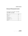
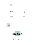
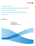
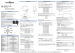
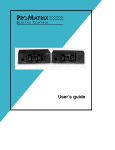
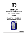
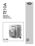
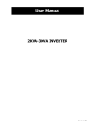
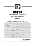
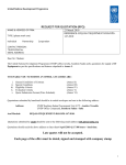
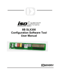
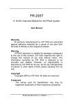
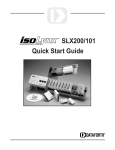
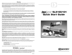
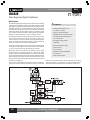
High Performance Signal Conditioners
DSCA
DSCA38
Strain Gage Input Signal Conditioners
Description
Each DSCA38 strain gage input module provides a single channel of strain gage
input which is filtered, isolated, amplified, and converted to a high-level voltage
output (Figure 1). Signal filtering is accomplished with a five-pole filter which is
optimized for step response. An anti-aliasing pole is located on the field side of
the isolation barrier, and the other four poles are on the system side. After the
initial field-side filtering, the input signal is chopped by a proprietary chopper
circuit. Isolation is provided by transformer coupling, again using a proprietary
technique to suppress transmission of common mode spikes or surges.
S
The DSCA38 can interface to transducers with a nominal resistance of 100Ω to
10kΩ. Strain gage excitation is provided from the module by a stable 10V or
3.333V source. This source is fully isolated, allowing the amplifier inputs to
operate over the full range of the excitation voltage. This feature enables the
module to be interfaced to other sensors requiring exctitation.
• Input Protected to 240VAC Continuous
Module output is either voltage or current. For current output models a dedicated
loop supply is provided at terminal 3 (+OUT) with loop return located at terminal
4 (-OUT). The system-side load may be either floating or grounded.
• Fully Isolated Excitation Supply
Special input circuits provide signal input and excitation protection against
accidental connection of power-line voltages up to 240VAC and against
transient events as defined by ANSI/IEEE C37.90.1. Protection circuits are also
present on the signal output and power input terminals to guard against transient
events and power reversal. Signal and power lines are secured to the module
using screw terminals which are in pluggable terminal blocks for ease of system
assembly and reconfiguration.
• Easily Mounts on Standard DIN Rail
The modules have excellent stability over time and do not require recalibration,
however, zero and span settings are adjustable up to ±5% to accommodate
Features
• Interfaces to 100Ω through 10kΩ Strain Gages
• Industry Standard Output of ±10V,
0 to 20mA, or 4 to 20mA
• 1500Vrms Transformer Isolation
• ANSI/IEEE C37.90.1 Transient Protection
• True 3-Way Isolation
• Wide Range of Supply Voltage
• 100dB CMR
• ±0.03% Accuracy
• ±0.01% Linearity
• C-UL-US Listed
• CE and ATEX Compliant
situations where fine-tuning is desired. The zero adjustment can be used to
offset bridge imbalances. The adjustments are made using potentiometers
located under the front panel label and are non-interactive for ease of use.
Figure 1: DSCA38 Block Diagram
210
For information call 800-444-7644
©1995-2014 Dataforth Corporation, All Rights Reserved ISO9001:2008-Registered QMS
High Performance Signal Conditioners
Module
Input Range
Input Bias Current
Input Resistance
Normal
Power Off
Overload
Signal Input Protection
Continuous
Transient
Excitation
Output
Half Bridge Output Level
Load Resistance (10V)
Load Resistance (3.33V)
Load Regulation
Stability
Protection
Continuous
Transient
Output Range
Load Resistance (IOUT)
Current Limit
Output Protection
Short to Ground
Transient
CMV, Input to Output, Input to Power
Continuous
Transient
CMV, Output to Power
Continuous
CMR (50Hz or 60Hz)
Accuracy(1)
Linearity
Adjustability
Stability
Input Offset
Output Offset
Gain
Output Noise, 100kHz Bandwidth
Bandwidth, –3dB
NMR
Response Time, 90% Span
Power Supply
Voltage
Current
Sensitivity
Protection
Reverse Polarity
Transient
Environmental
Operating Temperature Range
Storage Temperature Range
Relative Humidity
Emissions EN61000-6-4
Radiated, Conducted
Immunity EN61000-6-2
RF
ESD, EFT
Mechanical Dimensions
(h)(w)(d)
Mounting
Ordering Information
Typical❇ at TA=+25°C and +24VDC supply voltage
Model
Input
Bridge
Type
DSCA38-01
DSCA38-02
DSCA38-03
DSCA38-04
DSCA38-05
DSCA38-06
DSCA38-07
DSCA38-08
DSCA38-09
DSCA38-10
DSCA38-11
DSCA38-12
DSCA38-13
DSCA38-14
DSCA38-15
DSCA38-16
DSCA38-17
DSCA38-18
DSCA38-19
DSCA38-20
DSCA38-21
Full
Full
Half
Half
Full
Full
Full
Full
Full
Half
Half
Full
Full
Full
Full
Full
Half
Half
Full
Full
Full
DSCA38
±10mV to ±100mV
±0.5nA
50MΩ
65kΩ
65kΩ
240Vrms max (Full Bridge)
120Vrms max (Half Bridge)
ANSI/IEEE C37.90.1
10V ±0.03% or 3.33V ±0.03%
Excitation Output/2 ±0.03%
300Ω to 10kΩ
100Ω to 10kΩ
±5ppm/mA
±15ppm/°C
240Vrms max
ANSI/IEEE C37.90.1
See Ordering Information
600Ω max
8mA (VOUT), 30mA (IOUT)
Continuous
ANSI/IEEE C37.90.1
1500Vrms max
ANSI/IEEE C37.90.1
50VDC max
100dB
±0.03% Span
±0.01% Span
±5% Zero and Span
Input Range
–10mV
–30mV
–10mV
–30mV
–20mV
–33.3mV
–100mV
–10mV
–30mV
–10mV
–30mV
–20mV
–33.3mV
–100mV
0
0
0
0
0
0
0
Output
Range†
Excitation Sens.
to +10mV
to +30mV
to +10mV
to +30mV
to +20mV
to +33.3mV
to +100mV
to +10mV
to +30mV
to +10mV
to +30mV
to +20mV
to +33.3mV
to +100mV
to +10mV
to +30mV
to +10mV
to +30mV
to +20mV
to +33.3mV
to +100mV
+3.333V
+10.0V
+3.333V
+10.0V
+10.0V
+3.333V
+10.0V
+3.333V
+10.0V
+3.333V
+10.0V
+10.0V
+3.333V
+10.0V
+3.333V
+10.0V
+3.333V
+10.0V
+10.0V
+3.333V
+10.0V
3mV/V
3mV/V
3mV/V
3mV/V
2mV/V
10mV/V
10mV/V
3mV/V
3mV/V
3mV/V
3mV/V
2mV/V
10mV/V
10mV/V
3mV/V
3mV/V
3mV/V
3mV/V
2mV/V
10mV/V
10mV/V
1
1
1
1
1
1
1
2, 3, 4
2, 3, 4
2, 3, 4
2, 3, 4
2, 3, 4
2, 3, 4
2, 3, 4
2, 3, 4
2, 3, 4
2, 3, 4
2, 3, 4
2, 3, 4
2, 3, 4
2, 3, 4
Output Ranges Available
†
Output Range
Part No. Suffix
1. –10V to +10V
2. 0V to +10V
3.
4 to 20mA
4.
0 to 20mA
NONE
NONE
C
E
Example
DSCA38-01
DSCA38-08
DSCA38-08C
DSCA38-08E
±1µV/°C
±6ppm/°C (VOUT), ±20ppm/°C (IOUT)
±55ppm/°C
750µVrms (VOUT), 3µArms (IOUT)
DSCA
Specifications
DSCA
3kHz
100dB/Decade Above 3kHz
170µs
19 to 29VDC
60mA (VOUT), 80mA (IOUT)
±0.0002%/%
Figure 2: Half Bridge Connection
Continuous
ANSI/IEEE C37.90.1
–40°C to +80°C
–40°C to +80°C
0 to 95% Noncondensing
ISM, Group 1
Class A
ISM, Group 1
Performance A ±0.5% Span Error
Performance B
2.95" x 0.89" x 4.13"
(75mm x 22.5mm x 105mm)
DIN EN 50022 -35x7.5 or -35x15 rail
NOTES:
❇
Contact factory or your local Dataforth sales office for maximum values.
(1) Includes linearity, hysteresis and repeatability. (2) Strain Element.
Figure 3: Quarter Bridge Connection
Installation Notes:
1.) This Equipment is Suitable for Use in Class I, Division 2, Groups A, B, C, D, or Non-Hazardous Locations Only.
2.) Warning - Explosion Hazard - Substitution of Components May Impair Suitability for Class I, Division 2.
3.) Warning - Explosion Hazard - Do Not Disconnect Equipment Unless Power Has Been Switched Off or The
Area is Known to be Non-Hazardous.
Visit our website www.dataforth.com
211
©1995-2014 Dataforth Corporation, All Rights Reserved ISO9001:2008-Registered QMS