1
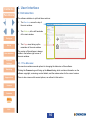
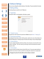
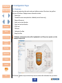
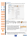
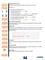
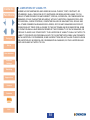
Portables-Pro 2
User Manual
H2S
CO
CH4
Portables-Pro
2
Quick and simple in-field gas test
and calibration solution
Click here for
navigation
instructions
Click here for
functions
list
Click here for
full contents
list
M070040
Issue 1 Sep 2015
Contents
NAVIGATION INSTRUCTIONS
Functions
The symbols in the left-hand margin of each page of the manual will enable you to carry out the
following functions:
ii
The buttons below do not function. They are for illustrative purposes only.
Contents
Click on this button to display the Contents page.
Click on this button to display the previous page.
Click on this button to display the next page.
Click on this button to display the previous view (use it to return from a reference jump).
Click on this button to display next view (use it to return to a reference jump).
Click this button to print some or all of the document (specific pages can be chosen).
Exit
!!
Click this button to exit the user guide.
Press the Esc key to display normal Acrobat© Controls.
Contents
FUNCTIONS
Set-up
Quick Start Guide
User Interface
Software Settings
Appendices
CONTENTS
Functions
Prologue. . . . . . . . . . . . . . . . . . . . . . . . . . . . . . . . . . . . . . . . . . . . . . . . . 6
General. . . . . . . . . . . . . . . . . . . . . . . . . . . . . . . . . . . . . . . . . . . . . . . . . . . . . . . . 6
1.Set-up . . . . . . . . . . . . . . . . . . . . . . . . . . . . . . . . . . . . . . . . . . . . . . . . 7
1.1 System requirements . . . . . . . . . . . . . . . . . . . . . . . . . . . . . . . . . . . . . . . . . 7
1.2 Software installation. . . . . . . . . . . . . . . . . . . . . . . . . . . . . . . . . . . . . . . . . . 7
2. Quick Start Guide. . . . . . . . . . . . . . . . . . . . . . . . . . . . . . . . . . . . . . . 8
2.1 Starting the Software . . . . . . . . . . . . . . . . . . . . . . . . . . . . . . . . . . . . . . . . . 8
2.1.1 Registering Portables-Pro 2. . . . . . . . . . . . . . . . . . . . . . . . . . . . . . . . 8
2.1.2 Creating a Setup. . . . . . . . . . . . . . . . . . . . . . . . . . . . . . . . . . . . . . . . . 8
2.1.3 Connecting to a Device. . . . . . . . . . . . . . . . . . . . . . . . . . . . . . . . . . . . 9
3. User Interface. . . . . . . . . . . . . . . . . . . . . . . . . . . . . . . . . . . . . . . . . 10
3.1 Introduction. . . . . . . . . . . . . . . . . . . . . . . . . . . . . . . . . . . . . . . . . . . . . . . . 10
3.1.1 The Menubar . . . . . . . . . . . . . . . . . . . . . . . . . . . . . . . . . . . . . . . . . . . 10
3.1.2 The Device Menu. . . . . . . . . . . . . . . . . . . . . . . . . . . . . . . . . . . . . . . . 11
3.1.3 The View Menu. . . . . . . . . . . . . . . . . . . . . . . . . . . . . . . . . . . . . . . . . . 12
3.1.4 The Tools Menu. . . . . . . . . . . . . . . . . . . . . . . . . . . . . . . . . . . . . . . . . 12
3.1.5 The Help Menu. . . . . . . . . . . . . . . . . . . . . . . . . . . . . . . . . . . . . . . . . . 13
3.1.6 The Sidebar. . . . . . . . . . . . . . . . . . . . . . . . . . . . . . . . . . . . . . . . . . . . 13
4. Software Settings. . . . . . . . . . . . . . . . . . . . . . . . . . . . . . . . . . . . . . 17
4.1 Settings Dialog . . . . . . . . . . . . . . . . . . . . . . . . . . . . . . . . . . . . . . . . . . . . . 17
4.1.1 Application. . . . . . . . . . . . . . . . . . . . . . . . . . . . . . . . . . . . . . . . . . . . . 17
4.1.2 Scanning . . . . . . . . . . . . . . . . . . . . . . . . . . . . . . . . . . . . . . . . . . . . . . 18
4.1.3 Localisation. . . . . . . . . . . . . . . . . . . . . . . . . . . . . . . . . . . . . . . . . . . . 19
4.1.4 Reports. . . . . . . . . . . . . . . . . . . . . . . . . . . . . . . . . . . . . . . . . . . . . . . . 20
4.2 Database Management. . . . . . . . . . . . . . . . . . . . . . . . . . . . . . . . . . . . . . . 21
4.2.1 Settings . . . . . . . . . . . . . . . . . . . . . . . . . . . . . . . . . . . . . . . . . . . . . . . 21
4.2.2 Setups . . . . . . . . . . . . . . . . . . . . . . . . . . . . . . . . . . . . . . . . . . . . . . . . 21
4.2.3 Reports. . . . . . . . . . . . . . . . . . . . . . . . . . . . . . . . . . . . . . . . . . . . . . . . 21
4.2.4 Logs. . . . . . . . . . . . . . . . . . . . . . . . . . . . . . . . . . . . . . . . . . . . . . . . . . 21
Exit
4
Functions
4.3 Configuration Pages. . . . . . . . . . . . . . . . . . . . . . . . . . . . . . . . . . . . . . . . . 22
4.3.1 Summary . . . . . . . . . . . . . . . . . . . . . . . . . . . . . . . . . . . . . . . . . . . . . . 22
4.3.2 Configuration. . . . . . . . . . . . . . . . . . . . . . . . . . . . . . . . . . . . . . . . . . . 23
4.3.3 Sensors . . . . . . . . . . . . . . . . . . . . . . . . . . . . . . . . . . . . . . . . . . . . . . . 28
4.3.4 Tools. . . . . . . . . . . . . . . . . . . . . . . . . . . . . . . . . . . . . . . . . . . . . . . . . . 31
4.3.5 Status. . . . . . . . . . . . . . . . . . . . . . . . . . . . . . . . . . . . . . . . . . . . . . . . . 32
4.3.6 Reports. . . . . . . . . . . . . . . . . . . . . . . . . . . . . . . . . . . . . . . . . . . . . . . . 33
4.3.7 Logging . . . . . . . . . . . . . . . . . . . . . . . . . . . . . . . . . . . . . . . . . . . . . . . 35
5.Servicing. . . . . . . . . . . . . . . . . . . . . . . . . . . . . . . . . . . . . . . . . . . . .
Appendix A: Performing a Zero. . . . . . . . . . . . . . . . . . . . . . . . . . . . .
Appendix B: Performing a Bump Test. . . . . . . . . . . . . . . . . . . . . . . .
Appendix C: Performing a Calibration . . . . . . . . . . . . . . . . . . . . . . .
Appendix D: Replacing Sensors . . . . . . . . . . . . . . . . . . . . . . . . . . . .
Appendix E: Fleet Management. . . . . . . . . . . . . . . . . . . . . . . . . . . . .
Software license agreement. . . . . . . . . . . . . . . . . . . . . . . . . . . . . . . .
42
43
44
45
46
47
48
1. GRANT OF LICENSE. . . . . . . . . . . . . . . . . . . . . . . . . . . . . . . . . . . . . . . . . . 48
2. DESCRIPTION OF OTHER RIGHTS AND LIMITATIONS.. . . . . . . . . . . . . . 48
3. TITLE.. . . . . . . . . . . . . . . . . . . . . . . . . . . . . . . . . . . . . . . . . . . . . . . . . . . . . . 49
4. TERMINATION.. . . . . . . . . . . . . . . . . . . . . . . . . . . . . . . . . . . . . . . . . . . . . . . 49
5. EXPORT CONTROLS.. . . . . . . . . . . . . . . . . . . . . . . . . . . . . . . . . . . . . . . . . 49
6. MISCELLANEOUS. . . . . . . . . . . . . . . . . . . . . . . . . . . . . . . . . . . . . . . . . . . . 49
7. LIMITED WARRANTY.. . . . . . . . . . . . . . . . . . . . . . . . . . . . . . . . . . . . . . . . . 50
8. LIMITATION OF LIABILITY.. . . . . . . . . . . . . . . . . . . . . . . . . . . . . . . . . . . . . 51
Crowcon contacts. . . . . . . . . . . . . . . . . . . . . . . . . . . . . . . . . . . . . . . . 52
Exit
5
Contents
Prologue
Functions
General
Portables-Pro 2 allows full configuration and control of your gas detector, and will provide the
following functions:
• Configuration of Devices
• Calibration of Devices
• Information Management
Prologue
Set-up
The level of access will depend upon the license issued to the user. There are 2 levels of access
available:
• Standard User (no license is required for this access level)
• Service User
This manual contains a description of all the available functions. A user’s license level will determine
the functions which may be accessed.
User Interface
Software
Settings
Servicing
Appendices
License
Contacts
Exit
6
Contents
Functions
1.Set-up
1.1 System requirements
The following are the minimum and recommended system requirements that will enable PortablesPro 2 to run:
Minimum Recommended
Prologue
• Processor
Single core, 1GHz
Dual/Quad Core, 3Ghz+
• Memory 512Mb
2Gb+
• Hard Drive 40 Gb+
40 Gb+
• Monitor resolution1024x7681920x1080
• Operating system
Windows XP SP3
Windows 7 or above
Set-up
1.2 Software installation
User Interface
Software
Settings
Servicing
Appendices
License
Contacts
ii
Ensure that all previous versions of Portables-Pro 2 have been uninstalled before
proceeding with the installation. Note that Portables-Pro 1 may still be installed along side
Portables-Pro 2.
XX If you have been supplied with the software in a zip file, first extract the zip file, and then run the
Autorun.exe found at this location.
XX If you have been supplied with the software on a
CD, insert the CD into your PC, navigate to the
CD drive and run the Autorun.exe on the CD.
XX The autorun application will then start up.
XX Select the Install Software option to install
Portables-Pro 2.
XX Follow the on-screen instructions until the
software is fully installed.
XX If required, also install the USB driver for
communicating with Crowcon devices.
XX Once the installation is finished, a shortcut will
be added to the Start Menu, under Crowcon,
and another shortcut will be added to your
Desktop.
Exit
7
Contents
Functions
2.Quick Start Guide
2.1 Starting the Software
Double click the Portables-Pro 2 icon
on your PC’s
desktop. If this is the first time you are launching the
application, it may take some time for the software to
arrange its databases and prepare other items before
displaying the main window.
2.1.1 Registering Portables-Pro 2
Prologue
Set-up
If you require a service software license for PortablesPro 2, you will require the appropriate key to unlock the
software.
XX Click Help and then Register Software
. You will be presented with the licensing terms.
XX Check the box and click Next. Your identification key will appear in the first textbox.
User Interface
Software
Settings
Servicing
Appendices
License
XX Click the Email Support button to automatically generate an email to send to Crowcon technical
support to request a licensing key. Be sure to inform technical support of your credentials to
confirm that you are entitled to use the Servicing version of Portables-Pro 2.
XX Once you have received your key back from Crowcon technical support, enter it into the second
box on this page. The software will verify that the key is valid.
XX Click Finish.
Once the software is restarted, all servicing features will then be accessible.
2.1.2 Creating a Setup
Portables-Pro 2 may be used to create a setup without having a device connected.
XX Click File and then New Setup
, then enter a name for your setup. Note that this name must
be unique as the software will not allow duplicate names.
XX Click OK.
Contacts
You may then proceed to make modifications to this setup.
Exit
8
Contents
Functions
2.1.3 Connecting to a Device
XX Connect your T4 to your PC via Crowcon’s USB Communications Lead (Part Number CH0103).
If this is the first time connecting to the USB Communications Lead, wait for Windows to
acknowledge that it has configured the driver.
XX Click on the Devices button at the top-left of the main window. The software will then proceed to
perform a scan, and then connect to your T4 and bring up the summary page once it is found.
The summary page will give you an overview of the configuration of the device.
ii
If the date and time on the device is out of synchronisation with the local PC by more than
15 minutes, the software will prompt to re-synchronise the time.
Prologue
You may now proceed to configure, zero, bump test, calibrate or retrieve logs from your device.
Set-up
User Interface
Software
Settings
Servicing
Appendices
License
Contacts
Exit
9
Contents
Functions
3.User Interface
3.1 Introduction
The software interface is split into three sections:
1.The Menubar, across the top of
the main window.
2.The Sidebar, at the left hand side
of the main window.
Prologue
Set-up
User Interface
Software
Settings
3. The Page area, taking up the
remainder of the main window.
The version of the software is always
visible in the bottom-right corner of
the main window.
3.1.1 The Menubar
The menubar contains several options for changing the behaviour of the software.
Servicing
Appendices
Clicking the Crowcon logo will bring up the About dialog, which contains information on the
software copyright, versioning, contact details, and the release notes for the current version.
There is also a menu with several options, as outlined in this section.
License
Contacts
Exit
10
Contents
Functions
3.1.2 The Device Menu
Note that if connected to a setup rather than a device, this menu will display itself as the File menu. It
contains the following options:
3.1.2.1 New Setup
This option will bring up a dialog prompting for which
device type you would like to create a setup for, and
also a name. Note that the software will not allow you
to create a setup with a duplicate name.
Prologue
Set-up
User Interface
Software
Settings
Clicking on OK will create your setup within the
database and will then open this setup and set it as the
active device.
3.1.2.2 Open Setup
This option will bring up a dialog with a list of setups
stored in your database.
To open one of these setups, select it from the list and
click OK. This setup will then be opened and set as the
active device.
Servicing
3.1.2.3 Scan for Devices
Appendices
License
Contacts
This option will start a device scan. Any discovered devices will then be added to the devices
section of the sidebar.
3.1.2.4 Disconnect
If there is an active device, selecting this option will disconnect from it and drop the software
back to the Home page.
3.1.2.5 Exit
This option will cause the software to close.
Exit
11
Contents
Functions
3.1.3 The View Menu
This menu contains quick-access options for changing the appearance and behaviour of the
software.
ii
These items may be identified as being enabled as they will have their icon highlighted in
orange.
3.1.3.1 Disable Transitions
If this option is selected, the software will no longer use slide and fading animations. It will
also reduce the rate at which charts scroll. This is useful for improving performance on
slower PCs, and those which do not have multicore processors.
Prologue
3.1.3.2 Collapse Sidebar
Selecting this option will reduce the size of the sidebar. Some information will no longer be
visible, and the notifications section will be removed entirely. This is useful for laptop users
with smaller displays who wish to maximise the viewing area of the current page.
Set-up
User Interface
Software
Settings
Servicing
Appendices
License
3.1.3.3 Borderless Mode
Selecting this option whilst the software isn’t maximised will reduce the size of the window
border.
3.1.4 The Tools Menu
This menu contains several options for managing the behaviour of the software, the database, and
diagnostic output.
3.1.4.1 Settings
This option will bring up the Settings dialog. See the Software Settings section on page 17
for more details.
3.1.4.2 Database Management
This option will bring up the Database Management dialog. See the Software Settings
section on page 17 for more details.
Contacts
3.1.4.3 Output Logging
This will bring up the output logging tool, which contains a trace of all actions which have
occurred within the software. It is provided for informational purposes only, but may be useful
for diagnosing where a problem with an instrument has occurred.
Exit
Note that this option is only available for users with a service license.
12
Contents
Functions
3.1.5 The Help Menu
This menu contains several options for getting help on use of the application, and updating your
license key.
3.1.5.1 Support Website
This option will open up your default web browser on the Crowcon technical support website.
3.1.5.2 Email Support
This option will open up your default email client with an email template to Crowcon technical
support.
Prologue
Set-up
3.1.5.3 Register Software
This option will bring up the Register Software dialog. See the Registering Portables-Pro 2
section on page 8 for more information.
3.1.5.4 About
User Interface
Software
Settings
Servicing
Appendices
License
This option will bring up the About dialog, which contains information on the software
copyright, versioning, contact details, and the release notes for the current version.
3.1.6 The Sidebar
3.1.6.1 Devices
The Devices section shows all currently detected devices, and all open setups. Clicking on the
Devices section will start a scan for devices, which upon detection will appear below the button.
Note that when a device is selected the software will check that the time is synchronised with the
local PC, and give you the option of re-synchronising if it is out by more than 15 minutes.
Each listed device or setup will show an image of the device, the device type (e.g. “T4”), and the
serial number or setup name. A device may be removed from the list by clicking the X button.
Contacts
Exit
13
Contents
Functions
The Active Device
It is important to understand the concept of the active device, as although the software will allow
connection to as many devices as you like, you may only work with one at a time; the active device.
The active device can be identified as the item with bold and highlighted text, and a colour image. All
other devices will have their image greyed out, and non-bold text.
The active device also has some extra features:
• An indication of when the device is communicating.
• A Mute
Prologue
Set-up
User Interface
Software
Settings
Servicing
Appendices
License
button.
• The X button now serves to Disconnect from the device
rather than remove it from the list.
The circle indicator will flash green when communications are in progress, or may flash red if there is
a communications problem, for example if the device is prematurely unplugged from the PC.
The Mute
button will silence all audible alarms from the device, and vice versa if clicked again.
Switching between Devices
In the example to the right, there are two devices listed in the section. The
first is the active device, and the second is a loaded setup. Placing the mouse
over the second item will change the pointer to a hand, highlight the item, and
prompt the user to Connect to this setup. Clicking on this second item will set
then it as the active device.
If a device is no longer available, for example because it is no longer connected to the PC, then an
error message will be displayed to inform that the device cannot be connected to at this time.
ii
A physical device will have its communication indicator replaced with a USB symbol
whilst inactive.
Contacts
Exit
14
Contents
Functions
3.1.6.2 Notifications
The Notifications section may contain several messages of varying severity, from
Warning, to
Fault.
Information, to
Notifications are always in relation to the active device, so switching between devices may change
the contents of the Notifications section depending upon the state of those devices.
• Calibration Due and Bump Due notifications are denoted with a
Fault icon. Clicking on
these notifications will change the display to the Status page, or Service page if the user has a
service license.
• Positive Safety is denoted with a
display to the Status page.
Prologue
Set-up
User Interface
Software
Settings
Servicing
Warning icon. Clicking on this notification will change the
• If your software license is due to expire soon, an
Information notification will be shown.
Clicking this notification will bring up the Register dialog.
Clicking on the Notifications header button will cause all visible notifications to be hidden for the
remainder of this session.
3.1.6.3 Pages
The Pages section of the sidebar shows all sections of the software which are currently accessible.
Note that without a selected device, some of these options will not appear in the sidebar, for example
the Configuration option will only be visible when a device or setup is selected.
Though these pages are listed here, their functions are individually described in a later section of this
manual.
Home
Appendices
License
Contacts
The Home page gives information on how to get started with the software, and also informs
of the current state of the software license. This includes the license type and license expiry
date. This page is selectable by clicking the Pages header button.
Reports
The Reports page shows a list of all stored reports which may be displayed, and allows
filtering of this list based upon various parameters. This page is always accessible, so you
don’t need to be connected to a device to retrieve bump test and calibration reports.
Logging
Exit
The Logging page shows a list of all stored device event and data logs, and allows filtering
of this list based upon various parameters. The page may also be used to download logs
from a device. This page is always accessible, so you don’t need to be connected to a
device to retrieve data and event logs.
15
Contents
Functions
Summary
The Summary page gives an overview of the currently selected device, including which
sensors are fitted, the alarm levels on these sensors, and the calibration due dates.
Configuration
The Configuration page shows all configurable parameters on the selected device, and
allows modification of these parameters. The page can also be used to backup and restore
configurations for later use.
Sensors
Prologue
Set-up
User Interface
The Sensors page shows all configurable sensor parameters on the selected device, and
allows modification of these parameters. The page can also be used to backup and restore
sensor configurations for later use.
Tools
The Tools page shows an active gas level readout from the selected device. The page also
contains both the Zero and Bump Test tools.
Status
Software
Settings
The Status page shows any active status messages from the selected device.
Servicing
Servicing
The Servicing page contains several tools for performing servicing actions on a device.
Note that this page is only available to users who have a service license.
Appendices
License
Contacts
Exit
16
Contents
4.Software Settings
Functions
4.1 Settings Dialog
There are various settings that modify the behaviour of the software. These are described in this section.
The settings dialog is accessible from the Tools menu.
4.1.1 Application
These options relate to how the application will behave in general.
Prologue
Set-up
User Interface
Software
Settings
Servicing
4.1.1.1 Disable Transitions
This performs the same function as the option from the View menu (see Section 3.1.3 on page 12).
4.1.1.2 Reset Suppressed Dialogs
Appendices
License
Contacts
Some dialogs will present the user with a Yes/No question, and allow the user to set the software not to
show these dialogs again. Selecting this option will restore these dialogs so they are displayed again.
4.1.1.3 Enable Keep-Alive
This option enables and disables whether the software will occasionally communicate with a device
to ensure it is still there. This can be useful if you are likely to need to disconnect and reconnect a
single device often.
4.1.1.4 Colour Scheme
This option switches the software between Light and Dark mode. Some users express preference
for the dark colour scheme to reduce eye strain from reading dark-on-light text on a bright monitor.
Exit
ii
Changing this option will not take effect until the software is restarted.
17
Contents
4.1.2 Scanning
These options relate to how the software behaves when performing a device scan.
Functions
Prologue
Set-up
User Interface
Software
Settings
Servicing
Appendices
License
Contacts
4.1.2.1 Mute Device upon Detect
Selecting this option will cause the software to immediately set a device to be muted when it is
found. This is useful if you are frequently planning on performing calibrations or bump tests.
4.1.2.2 Perform a Scan at Startup
Selecting this option will cause the software to immediately perform a device scan when the software
is started up.
4.1.2.3 Automatically Select First Device
Selecting this option will cause the software to select the first device it finds as the active device
when performing a scan.
4.1.2.4 Stop Scan on First Device
Selecting this option will cause a scan to drop out when a single device has been found.
4.1.2.5 COM Ports
You may either select to Scan all ports, or alternatively select which ports you would like a scan to be
performed on. If you know which COM port has been assigned to your USB Communications Lead
then the scan will be fastest if only this COM port is selected.
4.1.2.6 Baud Rate
Exit
Different Crowcon devices communicate at different baud rates. For T4, ensure that the 38400
option is selected.
18
Contents
4.1.3 Localisation
These options relate to language settings for the software.
Functions
Prologue
Set-up
User Interface
Software
Settings
Servicing
4.1.3.1 Preferred Language
This option contains all detected languages in the software’s language folder. Updating this option
will cause all text within the software to then use the selected language file. Note that restarting the
software is advised after changing this option.
4.1.3.2 Temperature Units
This option will cause all displayed temperatures to be displayed in the selected unit.
Appendices
License
Contacts
Exit
19
Contents
4.1.4 Reports
These options relate to custom information that will be displayed on all generated reports.
Functions
Prologue
Set-up
User Interface
Software
Settings
Servicing
Appendices
License
4.1.4.1 Company Information
There are several fields for your company information. These must all be completed to appear on
your reports. You may leave some blank if you wish.
4.1.4.2 Logo
You may select a company logo to appear in the top-right corner of all reports. Acceptable formats
are bmp, jpeg and png.
We advise that you use a high-resolution image to achieve the best results.
4.1.4.3 Statement of Conformity
You may enter a statement of conformity to appear at the bottom of all bump test and calibration reports.
Contacts
Exit
20
Contents
Functions
4.2 Database Management
The database management dialog is accessible from the Tools menu.
Prologue
Set-up
User Interface
Software
Settings
Servicing
Appendices
4.2.1 Settings
These options relate to the settings for the software’s databases. There are both gas databases
which contain information for the configuration of sensors, and the user database which contains all
your configured setups, generated reports and downloaded logs.
4.2.1.1 User Database
You may select a different user database with this option. It is recommended that you take a backup
of your user database from time to time in case of data loss.
4.2.1.2 Gas Database
You may modify the location of where gas databases are loaded from with this option. Note that if
you change the location to one missing a database for a specific device, that device may not function
correctly with Portables-Pro 2.
All detected databases within the specified folder are listed in the table, along with device type and version.
License
Contacts
4.2.2 Setups
This page contains a list of all setups within the user database. You may rename a setup if it is the
only one ticked, or delete multiple setups at once. Note that when renaming a setup, press the enter
key when complete to confirm the entry, or your changes will be discarded.
4.2.3 Reports
This page contains a list of all reports within the user database. You may delete multiple reports at once.
4.2.4 Logs
Exit
This page contains a list of all logs within the user database. You may delete multiple logs at once.
21
Contents
Functions
4.3 Configuration Pages
4.3.1 Summary
The summary page shows the serial number and software version of the device, along with an
overview of all sensors. Displayed sensor information includes:
• Sensor type
• The date the sensor was production calibrated (service license only)
• Range of the sensor
• Alarm one level and direction
Prologue
• Alarm two level and direction
• STEL level
• TWA level
Set-up
User Interface
• Calibration Due Date
• Bump Due Date
ii
Calibration and bump due dates will be highlighted in red if they have expired, as in the
example image below.
Software
Settings
Servicing
Appendices
License
Contacts
Exit
The Refresh
button may be clicked at any time to re-retrieve this information from your device.
22
Contents
Functions
4.3.2 Configuration
The configuration page shows all non-sensor related parameters that may be modified on the
device.
Prologue
Set-up
User Interface
Software
Settings
Servicing
Appendices
4.3.2.1 Controls
At the top of the screen, the current device’s
information is displayed, along with the configuration
controls, including Undo
, Load
, Copy
and
Save
options.
Save
License
Contacts
When a section is modified in any way, the changed options
and the sections header will be highlighted and the Save
button will become enabled and will start flashing. Clicking
the Save button will then bring up the Progress dialog which
will report back on the outcome of the save operation. Click
OK to dismiss this dialog when it is finished.
Undo
Exit
When changes have been made to a configuration and changed options have been
highlighted, you may force the software to revert these changes by clicking the Undo button.
The software will then revert all highlighted changes.
23
Contents
Functions
Load
Selecting this option will bring up the Open Setup dialog. Selecting a setup and clicking
OK will then load this setup to the interface, highlighting any changed items. You then have
the option of making further modifications, saving the changes to the device with the Save
button, or discarding these changes with the Undo button.
Copy
Selecting this option will bring up the New Setup dialog. Enter a unique name for the setup,
and click OK. This will then save a copy of all the current displayed settings to the database.
4.3.2.2 Sections
Prologue
Set-up
Each section contains a series of categorised configuration options.
Production
These options are for display purposes only and are not modifiable.
User Interface
Software
Settings
Servicing
Appendices
Serial Number
This is the serial number of the active device.
Date of Manufacture
This is the date of which the device was manufactured.
General
These options control the general operation of the device.
License
Contacts
Exit
24
Contents
Functions
Home Screen Mode
You may select between Gas Readings and User Details.
The Gas Readings option will mean that the home screen will display current gas levels at all times.
The User Details option allows you to configure custom text to be displayed on the home screen,
unless there is an alarm condition in which case the device will revert to displaying gas readings. Line
one of the screen is configurable under Home Screen Text, and line two will display the current user.
Home Screen Text
This option is only applicable when Home Screen Mode is set to User Details. The text entered
here will be displayed on the top line of the of the T4 display whilst on the home screen.
Prologue
Set-up
User Interface
Software
Settings
Servicing
Appendices
License
Home Screen Gas Readings Flipped
This option will cause the home screen to display gas readings and headers inverted, so a user with
a device on their person may view gas readings. Note that this setting does not flip the screen under
any other conditions.
Startup Action
The option allows modification of the autozero function. Available options are Never Autozero,
Confirm Autozero, and Always Autozero.
• Never Autozero will cause the device to progress straight to the home screen when startup
has completed.
• Confirm Autozero will prompt the user with a countdown when startup has completed, at
which a button press will perform autozero.
• Always Autozero will prompt the user with the same countdown, but will perform autozero
regardless of whether they press the button or not.
Confidence Strategy
This option allows modification of how the device reports that it is functioning. Available options are
Off, Sounder, LED, Sounder & LED, Positive Safety, and Positive Safety & Sounder.
• Off will cause no audio visual confidence to be displayed.
• Sounder will cause the device will bleep at the configured Confidence Interval
• LED will cause the device to flash the blue LEDs at the configured Confidence Interval
Contacts
• Sounder & LED will cause the device to bleep and flash the blue LEDs at the configured
Confidence Interval
• Positive Safety will cause the device to flash either the green or red (depending upon state)
Positive Safety LED once per second.
Exit
• Positive Safety & Sounder will cause the device to flash either the green or red (depending
upon state) Positive Safety LED once per second, and bleep at the configured Confidence
Interval
25
Contents
Functions
Confidence Interval
This option is the time in seconds at which the Sounder or LED confidence strategies will perform.
Backlight Control
This option controls how long the backlight will stay on following a button press. Available options are
Always Off, 10 Second Timeout, 30 Second Timeout, and Always On.
• Always Off will keep the backlight always off, except under startup or alarm conditions.
• 10 second timeout will keep the backlight on for 10 seconds following a button press.
• 30 second timeout will keep the backlight on for 30 seconds following a button press.
• Always On will keep the backlight on indefinitely.
Prologue
Set-up
User Interface
Software
Settings
Servicing
Appendices
License
Contacts
Allow Calibration via Menu
This option allows the user to control whether the Calibration option is available via the T4 menu.
Bump Strategy
This option allows the user to control how the device handles bump testing. Available options are
Off, On – Menu Disabled, and On – Menu Enabled.
• Off will cause the device to ignore bump testing and never report bump due dates to the user.
Attempting to bump test via the menu will report a Bump Disabled message.
• On – Menu Disabled will cause the device to report bump due faults, and report bump due
dates to the user. Attempting to bump test via the menu will report a Bump Disabled message.
• On – Menu Enabled will cause the device to report bump due faults, and report bump due
dates to the user. The bump testing option will be available via the device menu.
ii
Bump testing may always be performed via Portables-Pro 2 or I-Test, regardless of what
this option is set to.
Bump Interval
This is the number of days which will be added to the current date to calculate the new bump due
date following a successful bump test.
Lock on Cal Due
This option allows the user to configure a device to lock if any sensor calibration due date expires.
Lock on Bump Due
This option allows the user to configure a device to lock if any sensor bump due date expires.
Threshold Logging
This option allows the user to configure whether the device data log will suspend if there are no gas
levels above threshold (see Logging Threshold on page 29 for more information).
Exit
Logging Interval
This is the time in seconds between each gas data log reading.
26
Contents
Functions
Prologue
Set-up
User Interface
Software
Settings
Splash Screen
The user may configure their own custom splash screen to be displayed at startup. A screen mockup is displayed as an indication of what the splash screen will look like.
Splash Enabled
This option enables or disables the custom splash screen.
Header Text
This option configures the text that will appear as the top line of the custom splash screen.
Info Text
This option configures the text that will appear as the bottom line of the custom splash screen.
Users
Up to five user names may be configured in the device.
Servicing
Appendices
License
Contacts
Active User
The active user may be configured by clicking the radio button by the side of the desired name.
User Names
Up to five user names may be entered here.
Exit
27
Contents
Time
The device’s current date and time is displayed here.
Functions
Prologue
Set-up
A custom date and time may be entered here if desired. Note that should the time be out of
synchronisation with the local PC by more than 15 minutes, the software will prompt to correct this
every time the device is connected to.
4.3.3 Sensors
The sensors page functions much in the same way as the Configuration page. See the Controls
section on page 23 for more information on the options at the top of the page.
User Interface
Software
Settings
Servicing
Appendices
License
Contacts
Exit
28
Contents
Functions
4.3.3.1 Fitted Sensors
This section is for informational purposes only. It shows the type of sensors which are fitted within
each bay on the device. No options may be modified here.
ii
If you wish to modify which sensors are fitted in the device, refer to the service manual.
4.3.3.2 Channels
This section contains all configurable settings for each channel, arranged in a grid for ease of use.
Prologue
Set-up
User Interface
Target Gas
Software
Settings
This option is for display purposes only. It displays the configured gas type for the appropriate channel.
Range
Servicing
Appendices
License
Contacts
This option is for display purposes only. It displays the range of the appropriate channel.
Calibration Interval
This is the number of days which will be added to the current date to calculate the new calibration
due date following a successful calibration for the appropriate channel.
Logging Threshold
This option is this variation from clean air that will be required to trigger logging to begin if threshold
logging is enabled.
ii
For Oxygen, the value is in relation to 20.9%vol, so 0.5 for example will mean the
threshold is either above 21.4%vol or below 20.4%vol.
Configured Gas
Exit
Flam sensors only. This option contains a list of gases which Crowcon support for use on the T4 flam
sensor. Available options are Methane, Hydrogen, Ethane, Acetylene and Propane.
29
Contents
Functions
Correction Factor
Flam sensors only. This option is for informational purposes only and is not configurable.
Alarm 1 Level
This is the gas level at which Alarm 1 will be triggered for the appropriate sensor.
Alarm 1 Direction
This is whether gas level must be rising or falling to trigger alarm 1.
Only configurable for Oxygen.
Prologue
Set-up
User Interface
Alarm 1 Latching
This is whether an alarm will automatically clear when the level drops below the alarm threshold.
Options are Latching or Non-Latching.
Alarm 2 Level
This is the gas level at which Alarm 2 will be triggered for the appropriate sensor.
Alarm 2 Direction
Software
Settings
This is whether gas level must be rising or falling to trigger alarm 2.
Servicing
STEL
Appendices
License
Contacts
Only configurable for Oxygen.
This is the alarm level for the 15 minute STEL alarm. Refer to the user & operator manual for further
details on the operation of STEL.
ii
Only available for toxic sensors.
TWA
This is the alarm level for the 8 hour TWA alarm. Refer to the user & operator manual for further
details on the operation of TWA.
ii
Only available for toxic sensors.
Exit
30
Contents
Functions
4.3.4 Tools
The tools page allows viewing of current gas and ADC levels, and also allows the user to Zero or
Bump Test the device.
Prologue
Set-up
User Interface
Software
Settings
Servicing
Appendices
License
Contacts
4.3.4.1 Graph
The graph shows all current readings from the device. To the left of the graph, each channel reading
can be seen under the Gas and ADC headings. The colour of a data series on the graph matches
the colour of the corresponding channel name at the left.
Show ADC Graph
You may choose this option to display a second graph of ADC readings.
Time History
Modifying this option changes the amount of time (in seconds) which is displayed on each graph.
Series Enabled
The checkboxes to the left of each channel header may be clicked to show or hide the appropriate
channel on the graphs.
Series Colours
Exit
The coloured box to the left of each channel header may be clicked to modify the colour of this data
series.
31
Contents
Functions
4.3.4.2 Zero
This tool guides the user through the process of performing a Zero operation. See Appendix A:
Performing a Zero on page 43 for more details.
4.3.4.3 Bump Test
This tool guides the user through the process of performing a Bump Test. See Appendix B:
Performing a Bump Test on page 44 for more details.
4.3.5 Status
Prologue
Set-up
This page displays all active fault and Positive Safety messages which are present on the active
device. This is useful for diagnosing what is causing the Positive Safety LED to be in the red state on
your device, or for getting more information on a fault message.
The page will automatically refresh every 5 seconds, or alternatively you can disable this function
and click the Refresh
button manually.
The example below shows the status page for a device which is due for a bump test.
User Interface
Software
Settings
Servicing
Appendices
License
Contacts
Exit
32
Contents
Functions
4.3.6 Reports
The reports page allows viewing of stored bump test and calibration reports, and also allows the
creation of configuration reports.
ii
If you wish to modify your company details on a report, this is done on the Settings
dialog.
Prologue
Set-up
User Interface
Software
Settings
Servicing
Appendices
License
4.3.6.1 Generate Configuration Report
This button will become available if the active device supports configuration reports. Clicking this
button will then generate a report for the active device. The report will then appear in the reports list.
4.3.6.2 Show only reports for Active Device
Contacts
This option will only be available if there is an active device. Checking this box will filter the reports
list to only show reports pertaining to the active device.
4.3.6.3 Filter by Serial
Exit
Entering a serial number (or part of a serial number) in this box will filter the contents of the reports
list. This text box will offer auto-complete options if the serial number you are typing appears in the
reports list.
33
Contents
Functions
4.3.6.4 Filter by Device
This option allows filtering by device type. All device types present in the reports list will appear in
this box.
4.3.6.5 Filter by Report
This option allows filtering by report type. All report types present in the reports list will appear in this box.
4.3.6.6 Filter by Date
This option allows filtering by date. Selecting a minimum and maximum date will only show reports
which occur between the two selected dates.
4.3.6.7 Reports List
Prologue
Set-up
The reports list shows all reports that meet the filter criteria. The headers of the list may be clicked to
sort the reports ascending or descending using our category of choice.
Clicking on an entry in the reports list will bring up the report in the viewer to the right of the page.
4.3.6.8 Report Controls
User Interface
Software
Settings
Servicing
When a report has been selected, a series of options along the top of the report viewer become
available, including zoom and page view controls, and a print option.
Print
Clicking the Print
button will bring up the print dialog with your default printer selected.
Export to PDF
Appendices
License
Contacts
Clicking the Export to PDF
location to export to.
button will bring up a dialog requesting a file name and
Zoom
There are three categories of zoom to select from, Full Page, Page Width, and Percentage.
Full Page will ensure the entire page is visible within the report area.
Page Width will zoom in so that the whole page width is visible. You may then scroll
downwards to view the rest of your report.
Percentage has several options to choose from for your preferred zoom level.
Page
Exit
You may use the forward
displayed report.
and back
buttons to navigate between pages on the currently
34
Contents
Functions
4.3.7 Logging
The logging page allows viewing of stored data and event logs, and also allows data and event logs
to be downloaded from the active device.
Prologue
Set-up
User Interface
Software
Settings
Servicing
4.3.7.1 Controls
Database
Appendices
License
Contacts
The database tab contains all stored log information.
Show only logs for Active Device
This option will only be available if there is an active device. Checking this box will filter the logs list
to only show logs pertaining to the active device.
Filter by Serial
Entering a serial number (or part of a serial number) in this box will filter the contents of the logs list.
This text box will offer auto-complete options if the serial number you are typing appears in the logs list.
Filter by Device
This option allows filtering by device type. All device types present in the logs list will appear in this box.
Exit
Filter by Type
This option allows filtering by log type. All log types present in the reports list will appear in this box.
35
Contents
Functions
Filter by Date
This option allows filtering by date. Selecting a minimum and maximum date will only show logs
which occur between the two selected dates.
Group Logs by Serial
This option will group together logs for the same device under a common group header.
Collate Event Logs
This option will place all event logs under the same item in the list, so the entire event log can be
viewed at once.
Prologue
Set-up
Logs List
The logs list shows all logs that meet our filter criteria. The headers of the list may be clicked to sort
the logs ascending or descending using our category of choice.
Clicking on an entry in the logs list will bring up the log in the viewer to the right of the page.
Device
User Interface
This option will only be available if there is an active device present.
Software
Settings
Servicing
Appendices
License
Contacts
Read Events
Clicking this button will start an event log download with the active device.
Once the download has begun, you will see the right hand side of the page filling with event logs on
the fly as they are processed. See Filtering on page 37 and Event Logs on page 41 for more
information.
You may Cancel this operation at any time.
Exit
ii
This process may take some time.
36
Contents
Functions
Clear Events
Clicking this button will clear the event log on the active device. The software will show a
confirmation dialog before proceeding with clearing.
Read Data
Clicking this button will start a data log download with the active device.
Once the download has begun, a new box will appear below the section with a list of log sections
which have been downloaded. You may select these at any time to view them. See Filtering on page
37 and Event Logs on page 41 for more information.
You may Cancel this operation at any time.
Prologue
Set-up
User Interface
Software
Settings
ii
This process may take some time.
Clear Data
Clicking this button will clear the data log on the active device. The software will show a confirmation
dialog before proceeding with clearing.
Filtering
Note that this page is context sensitive based upon the sort of logs which are being shown.
Event Filtering
When the displayed log is a list of event logs, the following options are available.
Servicing
Appendices
License
Contacts
Exit
37
Contents
Functions
Categorise Events by Colour
Selecting this option will switch between having individual events coloured or not.
Categories are:
• Blue: Power up or shutdown events, e.g.:
• Purple: Service events, e.g.:
• Green: Successful operations or Fault clearing or acknowledging, e.g.:
Prologue
Set-up
User Interface
Software
Settings
• Red: Failed operations or Fault set, e.g.:
Group Events by Log Start Time
If this option is selected, logs will have a separator line drawn between when the device has been
powered up and shut down.
Highlight Filter
Selecting an option from the highlight filter will allow your selected log type to be more easily spotted,
whilst still displaying all other log types. An example is shown below with “Alarm 1 Entered” as the
selected event type.
Servicing
Appendices
License
Contacts
Filter by Date
A minimum and maximum date can be specified to filter out logs which don’t fall between the two
values.
Filter by Event Type
Individual log types can be unticked from this list to remove them from the event list view. Clicking
the Event Type box will tick or untick all event types.
Data Filtering
When the displayed log is a data log, the following options are available.
Exit
38
Contents
Functions
Time Filtering
This displays as a double-ended track bar. The left tracker moves the start time of the log, and the
right tracker moves the end time of the log. The minimum visible section is approximately 10% of the
range of the graph.
Prologue
Set-up
User Interface
Reading Filtering
These filters are much like the time filtering option, only for either the left or right y-axis.
Software
Settings
Servicing
Appendices
License
Contacts
Exit
39
Contents
Functions
Events
If the event log has been downloaded and is available for this period of time, a selection of these
(e.g. calibration passed) will be shown on the graph in the appropriate location. You can enable or
disable these chart annotations using the checkboxes in this section.
Prologue
Set-up
User Interface
Software
Settings
Servicing
Appendices
License
Alarm events may take the following forms:
• A red bell with appropriate alarm type symbol for alarm entered.
• A green bell with appropriate alarm type symbol for alarm cleared.
• A blue bell with a tick mark for alarms acknowledged.
Only channel specific faults are displayed, e.g. over range, under range.
Calibration, Zero and Bump Test events may take the following forms:
• A green symbol for passed.
• A red symbol for failed.
Contacts
Exit
40
Contents
Functions
Event Logs
Event logs are displayed as a list of events in chronological order. You may scroll through these
events using the scrollbar to the right, or using your mouse scroll wheel.
Events may be exported to csv format by using the Export option at the bottom of the page.
See Filtering on page 37 for more information on manipulating this data.
Data Logs
Prologue
Set-up
Data logs are displayed on a graph, based upon a log start and end time. Moving the mouse over
the event log will display a vertical marker at the current mouse position, and the gas levels at this
position will be shown on the floating legend at the top of the page.
Items in the legend may be clicked to enable or disable them on the graph. If you find that the legend
is obscuring your view of the data, you may click the Right or Left arrow (as appropriate) to shift it to
the other side of the page.
Data may be exported to csv format by using the Export option at the bottom of the page.
User Interface
See Filtering on page 37 for more information on manipulating this data.
Software
Settings
Servicing
Appendices
License
Contacts
Exit
41
Contents
Functions
5.Servicing
For details on the servicing page, please refer to the Servicing manual.
Prologue
Set-up
User Interface
Software
Settings
Servicing
Appendices
License
Contacts
Exit
42
Contents
Functions
Appendix A: Performing a Zero
A zero may be performed on the Tools page. Once on the tools page, perform the following steps:
XX Select the Zero option at the bottom of the page.
XX Click Start Zero.
XX Select which sensors you would like to zero.
Prologue
Set-up
User Interface
Software
Settings
XX Ensure that the device is in clean air.
XX Click Next.
XX Wait for the zero process to complete.
Servicing
Appendices
XX View the results.
License
XX Click Finish.
Contacts
Exit
ii
You may Mute the device at any time by clicking the Mute
43
button.
Contents
Functions
Appendix B: Performing a Bump Test
A Bump Test may be performed on the Tools page. Once on the tools page, perform the following steps:
Ensure you have the appropriate gas prepared for performing the test, and a calibration cap.
XX Select the Bump Test option at the bottom of the page.
XX Click Start Bump Test.
XX Select which sensors you would like to bump test.
Prologue
Set-up
User Interface
Software
Settings
Servicing
Appendices
XX Enter the interval in days that will
be used to calculate new Bump
Due dates.
XX Connect the calibration cap to
the device.
XX Click Start Test.
XX Immediately apply gas to the device.
XX Allow the test to complete.
XX Turn off the gas.
License
Contacts
XX View the results.
XX Click Finish.
XX Navigate to the Reports page to view your Bump Test report.
Exit
ii
You may Mute the device at any time by clicking the
Mute
button.
44
Contents
Functions
Appendix C: Performing a Calibration
Refer to the service manual for information on performing calibrations.
Prologue
Set-up
User Interface
Software
Settings
Servicing
Appendices
License
Contacts
Exit
45
Contents
Functions
Appendix D: Replacing Sensors
Refer to the service manual for information on replacing sensors.
Prologue
Set-up
User Interface
Software
Settings
Servicing
Appendices
License
Contacts
Exit
46
Contents
Functions
Appendix E: Fleet Management
Unlike Portables-Pro 1, there is no explicit Fleet Management option within Portables-Pro 2. This is
because this function can be performed by other methods.
Users requiring a Fleet Management like function should perform the following steps:
1. Create a New Setup.
2. Navigate to the Configuration page and modify the General and Splash Screen sections to
have your required settings.
Prologue
Set-up
3. Click Save.
4. Navigate to the Sensors page and modify the Channels section to have your required settings.
5. Click Save.
6. Disconnect from the setup, and close it.
User Interface
7. Connect your T4 to be configured.
8. Navigate to the Configuration page (if required).
Software
Settings
9. Click Load.
10. Select your setup and click OK.
Servicing
Appendices
License
11. Click Save.
12. Navigate to the Sensors page (if required).
13. Click Load.
14. Select your setup and click OK.
15. Click Save.
Contacts
16. Disconnect from the T4, and close it.
17. Repeat steps 7-16 with your next device.
Exit
47
Contents
Functions
Prologue
Set-up
Software license agreement
IMPORTANT - READ CAREFULLY. THIS IS A LEGAL AGREEMENT BETWEEN YOU AND
CROWCON DETECTION INSTRUMENTS FOR THE SOFTWARE PRODUCT YOU ARE
INSTALLING WHICH INCLUDES COMPUTER SOFTWARE AND RELATED DOCUMENTATION.
BY INSTALLING OR OTHERWISE USING THE SOFTWARE, YOU ACCEPT ALL THE TERMS AND
CONDITIONS OF THIS AGREEMENT. IF YOU DO NOT AGREE TO THESE TERMS YOU MAY
WITHIN THIRTY (30) DAYS OF PURCHASE RETURN THE UNUSED SOFTWARE PRODUCT TO
THE LOCATION WHERE YOU OBTAINED IT FOR A REFUND.
Crowcon Detection Instruments Limited a Halma Group affiliate whose address is 172 Brook Drive,
Milton Park, Abingdon, Oxfordshire, OX14 4SD, UK, hereby grants to you a non-exclusive license (a
‘License’) to use the software product ‘Portables-Pro 2’ (the ‘Software’) and the accompanying printed
materials and User Manual (the ‘Documentation’) on the terms set forth below.
1. GRANT OF LICENSE.
This License grants you the following rights.
User Interface
Software
Settings
Servicing
Appendices
License
Contacts
Exit
Software
Except as set forth below you may use the Software on any single computer (A single computer
includes a ‘Portable’).
Transfer
You may transfer the Software and Documentation to a single recipient on a permanent basis
provided you retain no copies of the Software or Documentation (including backup or archival
copies) and the recipient agrees to the terms and conditions of this agreement. If the Software is an
upgrade any transfer must include all prior versions of the Software and Documentation.
2. DESCRIPTION OF OTHER RIGHTS AND LIMITATIONS.
Reverse Engineering
You may not modify, translate, reverse engineer, decompile, disassemble (except to the extent
applicable laws specifically prohibit such restrictions) or create derivative works based on the
Software, or any portion thereof.
Copying
You may not copy the Software or Documentation except as specifically provided by this Agreement.
Separation of Components
The Software is licensed as a single product. You may not separate the Software’s component parts
for use on more than one computer.
48
Contents
Functions
Upgrades
If the Software is an upgrade from another product, this upgrade License supersedes any previous
License. You may use the Software only in conjunction with the upgraded product, or you must
destroy the upgraded product.
Use of Crowcon’s Name
You may not use Crowcon’s or Crowcon’s suppliers’ name, logos, or trademarks in any manner
including, without limitation, in your advertising or marketing materials, except as is necessary to
affix the appropriate copyright notices as required herein.
3. TITLE.
Prologue
Set-up
User Interface
Software
Settings
Servicing
Appendices
License
Contacts
Exit
Title, ownership rights, and intellectual property rights in and to the Software and Documentation
shall remain in Crowcon and/or its suppliers. The Software and the Documentation is protected by
the copyright laws of international copyright treaties.
4. TERMINATION.
The License is in effect until terminated. The License will terminate automatically if you fail to comply
with the limitations described herein. On termination, you must destroy all copies of the Software and
Documentation.
5. EXPORT CONTROLS.
This Software is subject to the export control laws of the United Kingdom. You may not export or reexport the Software without the appropriate United Kingdom and foreign government licenses. You
shall otherwise comply with all applicable export control laws and shall defend, indemnify and hold
Company and all Company suppliers harmless from any claims arising out of your violation of such
export control laws.
6. MISCELLANEOUS.
This Agreement represents the complete agreement concerning this license between the parties
and supersedes all prior agreements and representations between them. This Agreement may be
amended only in writing executed by both parties.
THE ACCEPTANCE OF ANY PURCHASE ORDER PLACED BY YOU IS EXPRESSLY MADE
CONDITIONAL ON YOUR ASSENT TO THE TERMS SET FORTH HEREIN, AND NOT THOSE
CONTAINED IN YOUR PURCHASE ORDER.
If any provision of this Agreement is held to be unenforceable for any reason, such provision shall be
reformed only to the extent necessary to make it enforceable and the remainder of this Agreement
shall nonetheless remain in full force and effect.
49
Contents
Functions
Prologue
Set-up
User Interface
Software
Settings
Servicing
Appendices
License
7. LIMITED WARRANTY.
Crowcon warrants that the media containing the Software, if provided by Crowcon, is free from
defects in material and workmanship and will so remain for ninety (90) days from the date you
acquired the Software. Crowcon’s sole liability, and your sole remedy, for any breach of this warranty
shall be, in Crowcon’s sole discretion: (i) to replace your defective media; or (ii) if the above remedy
is impracticable, to refund the License fee you paid for the Software. Replaced Software and
Documentation shall be covered by this limited warranty for the period remaining under the warranty
that covered the original Software, or if longer, for thirty (30) days after the date of shipment to you
of the replaced Software. Only if you inform Crowcon of your problem with the Software during the
applicable warranty period and provide evidence of the date you acquired the Software will Crowcon
be obligated to honour this warranty. Crowcon will use reasonable commercial efforts to replace or
refund pursuant to the foregoing warranty within thirty (30) days of being so notified.
THIS IS A LIMITED WARRANTY AND IT IS THE ONLY WARRANTY MADE BY CROWCON.
CROWCON MAKES NO OTHER WARRANTY, REPRESENTATION, OR CONDITION,
EXPRESS OR IMPLIED, AND EXPRESSLY DISCLAIMS THE IMPLIED WARRANTIES OF
MERCHANTABILITY, FITNESS FOR A PARTICULAR PURPOSE, AND NONINFRINGEMENT
OF THIRD PARTY RIGHTS. THE DURATION OF IMPLIED WARRANTIES OR CONDITIONS,
INCLUDING WITHOUT LIMITATION, WARRANTIES OR CONDITIONS OF MERCHANTABILITY
AND OF FITNESS FOR A PARTICULAR PURPOSE, IS LIMITED TO THE ABOVE LIMITED
WARRANTY PERIOD; SOME JURISDICTIONS DO NOT ALLOW LIMITATIONS ON HOW LONG
AN IMPLIED WARRANTY OR CONDITION LASTS, SO LIMITATIONS MAY NOT APPLY TO YOU.
NO CROWCON AGENT OR EMPLOYEE IS AUTHORIZED TO MAKE ANY MODIFICATIONS,
EXTENSIONS, OR ADDITIONS TO THIS WARRANTY.
If any modifications are made to the Software by you during the warranty period; if the media is
subjected to accident, abuse, or improper use; or if you violate the terms of this Agreement, then this
warranty shall immediately be terminated. This warranty shall not apply if the Software is used on or
in conjunction with hardware or software other than the unmodified version of hardware and software
with which the Software was designed to be used as described in the Documentation.
THIS WARRANTY GIVES YOU SPECIFIC LEGAL RIGHTS, AND YOU MAY HAVE OTHER LEGAL
RIGHTS THAT VARY BY JURISDICTION.
Contacts
Exit
50
Contents
Functions
Prologue
8. LIMITATION OF LIABILITY.
UNDER NO CIRCUMSTANCES AND UNDER NO LEGAL THEORY, TORT, CONTRACT, OR
OTHERWISE, SHALL CROWCON OR ITS SUPPLIERS OR RESELLERS BE LIABLE TO YOU
OR ANY OTHER PERSON FOR ANY INDIRECT, SPECIAL, INCIDENTAL, OR CONSEQUENTIAL
DAMAGES OF ANY CHARACTER INCLUDING, WITHOUT LIMITATION, DAMAGES FOR LOSS
OF GOODWILL, WORK STOPPAGE, COMPUTER FAILURE OR MALFUNCTION, OR ANY AND
ALL OTHER COMMERCIAL DAMAGES OR LOSSES, OR FOR ANY DAMAGES IN EXCESS OF
CROWCONS LIST PRICE FOR A LICENSE TO THE SOFTWARE AND DOCUMENTATION, EVEN
IF CROWCON SHALL HAVE BEEN INFORMED OF THE POSSIBILITY OF SUCH DAMAGES, OR
FOR ANY CLAIM BY ANY OTHER PARTY. THIS LIMITATION OF LIABILITY SHALL NOT APPLY TO
LIABILITY FOR DEATH OR PERSONAL INJURY TO THE EXTENT APPLICABLE LAW PROHIBITS
SUCH LIMITATION. FURTHERMORE, SOME JURISDICTIONS DO NOT ALLOW THE EXCLUSION
OR LIMITATION OF INCIDENTAL OR CONSEQUENTIAL DAMAGES, SO THIS LIMITATION AND
EXCLUSION MAY NOT APPLY TO YOU.
Set-up
User Interface
Software
Settings
Servicing
Appendices
License
Contacts
Exit
51
Contents
Functions
Prologue
Set-up
User Interface
Software
Settings
Servicing
Appendices
License
Contacts
Crowcon contacts
UK: C
rowcon Detection Instruments Ltd, 172 Brook Drive, Milton Park, Abingdon,
Oxfordshire OX14 4SD
Tel: +44 (0) 1235 557700
Fax: +44 (0) 1235 557749
Email: [email protected]
US: C
rowcon Detection Instruments Ltd, 1455 Jamike Ave, Suite 100, Erlanger, KY 41018
Tel: +1 859 957 1039 or 1 800 527 6926
Fax: +1 859 957 1044
Email: [email protected]
NL: C
rowcon Detection Instruments Ltd, Vlambloem 129, 3068JG, Rotterdam, Netherlands
Tel: +31 10 421 1232
Fax: +31 10 421 0542
Email: [email protected]
SG: Crowcon Detection Instruments Ltd, Block 194, Pandan Loop, #06-20 Pantech Industrial
Complex, Singapore, 128383
Tel: +65 6745 2936
Fax: +65 6745 0467
Email: [email protected]
CN: C
rowcon Detection Instruments Ltd (Beijing), Unit 316, Area 1, Tower B, Chuangxin Building,
12 Hongda North Road, Beijing Economic & Technological Development Area, Beijing,
China 100176
Tel: +86 10 6787 0335
Fax: +86 10 6787 4879
Email: [email protected]
www.crowcon.com
Exit
52