1
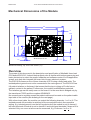
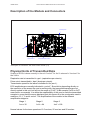
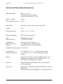
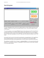
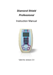
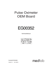
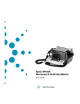
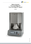
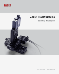
Medlab GmbH
Three Lead ECG OEM Module EG01010 User Manual
medlab
Three Lead
ECG OEM board
EG01010
Technical Manual
Copyright © Medlab 2008 - 2013
Version 1.02
1
Version 1.02
22.04.2013
Medlab GmbH
Three Lead ECG OEM Module EG01010 User Manual
Medlab GmbH
[email protected]
www.medlab-gmbh.de
Version 1.02
22.04.2013
2
Medlab GmbH
Three Lead ECG OEM Module EG01010 User Manual
Table of Contents
Mechanical Dimensions
4
Overview
4
Description of the Module and Connectors
5
Physical Units of Transmitted Data
5
Specifications
6
Connector Assignment
7
Compliance with IEC60601-2-27
8
Software Protocol Description
10
Serial Transmission
10
Serial Transmission Protocol
11
Commands accepted by the Module
12
PC Test Program
14
Regulatory Considerations
15
Document Revisions
15
3
Version 1.02
22.04.2013
Medlab GmbH
Three Lead ECG OEM Module EG01010 User Manual
Mechanical Dimensions of the Module
$OO 'LPHQVLRQV LQ PP
Mechanical drawing, top view of the module (1:1)
Overview
The scope of this document is the description and specification of Medlab's three lead
ECG board EG01010. It should help anybody who is familiar with both programming and
basic electronics to select the proper hardware and software version for his application
as well as to help him integrate the board into his own electronic system.
The EG01010 measures one of three channels of ECG using a three lead cable. The
isolated patient ground must not be connected to the mains ground. The EG01010 has
full patient isolation on the board, that means that the input voltage of 5 volts has no
galvanic contact to the patient. Furthermore, the module is defibrillation protected.
The isolation gap can be easily seen on the board: it is the area that is bridged only by
the transformer 76250 and the couplers ADUM2402.
No connections to anything except the patient cable must be made on the patient cable
input side of the module (see drawing on the next page).
With a three lead cable, the module can output the following channels: I or II or III. The
isolated ground of the module is switched to the unused electrode in the respective
setting, e.g. isolated ground is on the left leg electrode if the module is set to channel I,
left hand electrode if module is set to channel II and right hand electrode if channel III is
selected. Only one curve at a time can be measured, e.g. Einthoven I or II or III.
Version 1.02
22.04.2013
4
Medlab GmbH
Three Lead ECG OEM Module EG01010 User Manual
Description of the Module and Connectors
0RXQWLQJ +ROHV
&RQQHFWRU 5HVSLUDWLRQ %RDUG
3DWLHQW &DEOH
&RQQHFWRU
+RVW 3RZHU
&RQQHFWRU
3DWLHQW ,VRODWLRQ
&RQQHFWRU 5HVSLUDWLRQ %RDUG
Description of connectors and areas of the module (1:1)
Physical Units of Transmitted Data
Scaling of ECGs is done normally in the unit "cm/mV" for the Y-axis and in "mm/sec" for
the X-axis.
Respiration rate is transmitted in „rpm“ (respirations per minute).
Pulse rate is transmitted in „bpm“ (beats per minute).
Transmission speed for the wave is indicated in Hz (sec-1).
ECG amplitudes are normally indicated in „cm/mV“. Since this is depending directly on
the resolution of the screen the user is working with, the transmitted samples are not
directly scaled in this unit, but fall into the range of 0-0xF7 (8 Bit samples, 0xF8 to 0xFF
reserved for commands). It is within the responsibility of the user to scale the transmitted
samples in a way that the waves displayed onto his screen fit to the usual scales used in
medicine, 0.5, 1, 2 and 4 cm/mV. The amplification of the module in the different
amplification stages is:
Stage 1
Stage 2
Stage 3
1mv = 32
1mV = 64
1mV = 128
Normal values for the trace speed are 12.5 mm/sec, 25 mm/sec and 50 mm/sec.
5
Version 1.02
22.04.2013
Medlab GmbH
Three Lead ECG OEM Module EG01010 User Manual
Technical Data (Specifications)
Mechanical data:
88 mm x 53 mm
see page 4 for board drawing
4 layer PCB, thickness 1.5 mm
Maximum height:
With respiration option:
12 mm
25 mm
Attachment:
four M2.5 screws in the corners of the PCB
Weight:
32 g
Operating voltage:
5 Volt, +/- 10 %, 45 mA
Power consumption:
225 mW while measuring
Input:
Patient Isolation:
Defibrillation protected
CF, 4000 Volts RMS
Amplification:
Data transmission:
Filtering:
Three levels, user selectable
Three frequencies, user selectable
Integrated 50 Hz or 60 Hz notch filter
Amplifier frequency range: 0.05 to 70 Hz.
Pulse detection:
Respiration detection:
30 .. 248 bpm +/- 1%, +/- 1 Digit, 8 beat average
5 .. 99 rpm +/-3%, +- 1 Digit, 8 samples average
(option)
Output:
Asynchronous serial output with CMOS levels (0...5 V)
Hardware pulse trigger output, CMOS levels (0...5 V)
Both outputs fully isolated from patient
Protocol:
Standard bidirectional serial protocol, see description
on following pages
Connector:
Connectors compatible to Medlab EG05000 five channel
OEM board
Optional connectors for Medlab 00731 respiration board
Version 1.02
22.04.2013
6
Medlab GmbH
Three Lead ECG OEM Module EG01010 User Manual
Connectors
(see attached drawing for location)
Header for host connection:
JP1:
1
2
3
4
5
6
7
8
9
10
11
12
13
14
15
16
Ground
Ground
Txd (RS232 level +/- 5Volt)
Txd (TTL level)
Rxd (RS232 level +/- 5Volt)
Rxd (TTL level)
Not connected
Not connected
Not connected
Not connected
Pulse Trigger output
Pulse Trigger output
Shutdown (VCC level on this pin powers down module)
Shutdown (VCC level on this pin powers down module)
VCC input
VCC input
Note: The pulse trigger is a high active, rectangular signal with a pulse width of 33 ms. Delay to the R wave can be
adjusted by a command.
Header for patient cable connection
SV1:
1
2
3
4
5
6
7
Unused
SHIELD
LL-IN
RA-IN
LA-IN
SHIELD
Unused
7KUHH /HDG 3DWLHQW &DEOH
6KLHOG
6KLHOG
/HIW $UP
5LJKW $UP
/HIW /HJ
6KLHOG
, RU ,, RU ,,,
)LYH /HDG 3DWLHQW &DEOH
)RXU /HDG 3DWLHQW &DEOH
It is very important to connect the black clamp to the
left leg or hip, not to the right leg or hip of the
patient. If you connect it to the wrong leg, there is one
channel that shows no ECG at all, the II channel,
because the board tries to sense the voltage between
right arm and right leg in this case.
5LJKW /HJ
6KLHOG
/HIW $UP
5LJKW $UP
6KLHOG
, DQG ,, DQG ,,,
DQG D9/ DQG D95 DQG D9)
/HIW /HJ
6KLHOG
5LJKW /HJ
/HIW $UP
5LJKW $UP
/HIW /HJ
&KHVW
, DQG ,, DQG ,,,
DQG D9/ DQG D95 DQG D9) DQG &
ECG cable connection
Remark:
For respiration measurement (optional respiration board needed), electrodes should
be attached to chest and hip, not arm and leg.
7
Version 1.02
22.04.2013
Medlab GmbH
Three Lead ECG OEM Module EG01010 User Manual
Technical Description for TRF IEC 60601-2-27
When preparing a test report form (TRF) for proof of compliance of the user's medical product to
IEC60601-2-27:2005, the following remarks / technical data will be helpful or needed:
Input Impedance:
Common mode rejection ratio:
Input Dynamic Range:
Defibrillator Discharge Recovery:
Leads-off sensing current:
> 10 MOhm
> 90 dB at 50 Hz or 60 Hz
±5 mV AC, ±300 mV DC
<10 sec per IEC 601-2-27
<10 sec per AAMI EC13-1992
Applied currents less than 150 nA
The following information references particular sections of IEC 601-2-27
Respiration (optional) Section 6.8.2.bb.1)
Applied currents less than 80 µA @ 90 kHz square
Tall T-wave rejection. Section 6.8.2.bb.2)
T-wave of 1.2 mV amplitude will not affect heart rate determination.
Heart rate averaging. Section 6.8.2.bb.3)
TBD
Response to irregular rhythm. Section 6.8.2.bb.4)
A1) Ventricular bigeminy: the EG01010 counts both large and small QRS complexes to display a
rate of 80 bpm.
A2) Slow alternating ventricular bigeminy: the EG01010 counts both large and small QRS
complexes to display a rate of 60 bpm.
A3) Rapid alternating ventricular bigeminy: the EG01010 counts all QRS complexes to display a
rate of 120 bpm.
A4) Bi-directional systoles: the EG01010 counts all QRS complexes to display a rate of 90 bpm.
Heart rate meter response time. Section 6.8.2.bb.5)
a) Change from 80 to 120 BPM: 4 sec
b) Change from 80 to 40 BPM: 7 sec
Time to alarm for tachycardia. Section 6.8.2.bb.6)
Waveform B1:
Amplitude
0,5 mV
1 mV
2 mV
Waveform B2
Amplitude
1 mV
2 mV
4 mV
Time to alarm
1 sec
1 sec
1 sec
Time to alarm
1 sec
1 sec
1 sec
Pacemaker pulse display capability (See IEC 601-2-27 clause 50.102.12)
The EG01010 is capable of displaying the ECG signal in the presence of
pacemaker pulses with amplitudes of ±2 mV to ±700 mV and durations of
0.1 ms to 2.0 ms. An indication for the pacemaker pulse is provided.
Version 1.02
22.04.2013
8
Medlab GmbH
Three Lead ECG OEM Module EG01010 User Manual
Pacemaker pulse rejection (See IEC 601-2-27 clause 50.102.13)
Without over/undershoot:
a) For single (ventricular-only) pacemaker pulses alone, with 0.1 and 2.0 ms pulse-widths and ±2 mV
and ± 700 mV pulse-amplitudes, the EG01010 correctly displays heart rate as zero bpm
(Asystole).
b) For single (ventricular-only) pacemaker pulses with normally paced QRS-T, with 0.1 and 2.0 ms
pulse-widths and ±2 mV and ± 700 mV pulse-amplitudes, the EG01010 correctly displays heart
rate of the QRS-T rhythm (60 bpm for the specified test waveform).
c) For single (ventricular-only) pacemaker pulses with ineffectively paced QRS pattern, with 0.1 and
2.0 ms pulse-widths and ±2 mV and ± 700 mV pulse-amplitudes, the EG01010 correctly displays
heart rate of the underlying QRS-T rhythm (30 bpm).
d) For atrial/ventricular pacemaker pulses alone, with 0.1 and 2.0 ms pulse-widths and ±2 mV and ±
700 mV pulse-amplitudes, the EG01010 correctly displays heart rate of zero bpm (Asystole).
e) For atrial/ventricular pacemaker pulses with normally paced QRS-T, with 0.1 and 2.0 ms pulsewidths and ±2 mV and ± 700 mV pulse-amplitudes, the EG01010 correctly displays heart rate of
the QRS-T rhythm (60 bpm).
f) For atrial/ventricular pacemaker pulses with ineffectively paced QRS pattern, with 0.1 and 2.0 ms
pulse-widths and ±2 mV and ± 700 mV pulse-amplitudes, the EG01010 correctly displays heart
rate of the underlying QRS-T rhythm (30 bpm).
With over/undershoot:
a) For single (ventricular-only) pacemaker pulses alone, with 0.1 and 2.0 ms pulse-widths and ±2 mV
and ± 700 mV pulse-amplitudes, the EG01010 correctly displays heart rate of zero bpm
(Asystole).
b) For single (ventricular-only) pacemaker pulses with normally paced QRS-T, with 0.1 and 2.0 ms
pulse-widths and ±2 mV and ± 700 mV pulse-amplitudes, the EG01010 correctly displays heart
rate of the QRS-T rhythm (60 bpm).
c) For single (ventricular-only) pacemaker pulses with ineffectively paced QRS pattern, with 0.1 and
2.0 ms pulse-widths and ±2 mV and ± 700 mV pulse-amplitudes, the EG01010 correctly displays
heart rate of the underlying QRS-T rhythm (30 bpm).
d) For atrial/ventricular pacemaker pulses alone, with 0.1 and 2.0 ms pulse-widths and ±2 mV and ±
700 mV pulse-amplitudes, the EG01010 correctly displays heart rate of zero bpm (Asystole).
9
Version 1.02
22.04.2013
Medlab GmbH
Three Lead ECG OEM Module EG01010 User Manual
Serial Transmission
The normal connection to the board is done via serial, asynchronous communication at
9600 baud, 8 data bits, no parity bit and one stop bit. Both CMOS and RS232 (+/- 5 Volt
level) voltage levels are available.
This protocol is token oriented. Special marker bytes that are not present in the normal
data stream mark the meaning of the following byte.
The RS232 voltage levels are helpful during evaluation of the board, which can be done
using an ordinary PC and a special software. The connection in the customer’s final
system could be done through 0V/5V levels, which saves parts on the customer’s side of
the data stream.
Connector JP1 is compatible with the interface connector on Medlab’s EG05000 five
channel ECG OEM board. Therefore, test cables that have been built for this board can
also be used for the EG01010 board.
The EG01010 sends a continuous data stream and receives commands. Commands are
one byte characters, some of them have an additional parameter, others just toggle an
internal switch in the EG01010 module.
The neutral line of the ECG always lies at 128, the module transmits unsigned byte data.
While a lead off condition is active, a pulse value of 0 and a neutral line of 128 is
transmitted.
The module powers up with amplification set to level 0 and speed set to level 1, which
means lowest amplification stage and transmission of 100 sample points per second.
Simulation mode is off at power up, the notch filter is set to 50 Hz and monitoring mode
is selected.
For details, please see the protocol description on the following pages.
Version 1.02
22.04.2013
10
Medlab GmbH
Three Lead ECG OEM Module EG01010 User Manual
Serial Transmission Protocol
All data is transmitted at 9600 baud, 8 bits, 1 stop bit, no parity. Each time a pulse is
detected by the board's internal algorithm, a block with a new, averaged pulse rate is
transmitted. The pulse detector is of high quality, and the point in time where the pulse
marker (0xFA) is transmitted can be used for triggering applications that require to
synchronize other devices to a patient's R-wave.
The ECG wave sample points are transmitted continuously with 50, 100 or 300 bytes per
second, according to the user's last command. The curve sample points lie between 0
and 246, with the neutral line of the ECG being at 128.
Values that are higher than 246 (0xF6) are used for marking the following byte as a new
data values according to the following definition:
Marker byte
Meaning of following byte(s)
0xF8
wave sample points follow
0xF9
Respiration rate follows
(optional respiration board
needs to be present)
0xFA
Pulse value follows
0xFB
Info byte follows
0x11
The only info byte
defined is 0x11, "LEAD OFF"
Others may be added in the
future
Commands accepted by the module
"N"
"M"
"S" "0"
"S" "1"
"S" "2"
"A" "0"
"A" "1"
"A" "2"
"G" "0"
"G" "1"
"G" "2"
"D" "0"
"D" "1"
"5"
"6"
"C"
"T" "0"
"T" "1"
"T" "2"
"T" "9"
"P" "0"
"P" "1"
normal operation mode
switch to simulation mode
send ECG trace with 300 Hz
send ECG trace with 100 Hz
send ECG trace with 50 Hz
amplification stage 0
amplification stage 1
amplification stage 2
channel III
channel II
channel I
show ECG curve
show respiration curve
turn on 50 Hz notch filter
turn on 60 Hz notch filter
calibrate, send 1mV pulse
Pulse trigger 15 ms after R
Pulse trigger 50 ms after R
Pulse trigger 100 ms after R
Pulse trigger middle between R
Pacemaker detection off
Pacemaker detection on
Example transmitted data stream :
Wave Marker
Wave Sampl es
Pul se 120
Wave Marker
Wave Sampl es
0xF8
0x20 0x23 0x25
0xFA 0x78
0xF8
0x25 0x25 0x26
○
○
○
○ ○ ○ ○ ○ ○ ○ ○ ○ ○ ○ ○ ○ ○ ○ ○ ○ ○ ○ ○ ○ ○ ○○
○
○
○
Time
11
Version 1.02
22.04.2013
Medlab GmbH
Three Lead ECG OEM Module EG01010 User Manual
Commands accepted by the Module
All commands have a one or two byte structure. They are also sent to the module with 9600 baud. The
commands are sent in ASCII format.
Basic Bandwidth of ECG amplifier (Diagnostic or Monitoring mode):
„F“
Parameter: "0" or "1"
„0“
bandwidth of the amplifier DC-80 Hz Diagnostic mode
(bear in mind mains filter setting)
„1“
bandwidth of the amplifier 0.67-40 Hz Monitoring mode
(reset value)
„S“
extra strong filter, lower edge frequency 2 Hz
Transmission frequency of the waveform packet:
„S“
Parameter: "0", "1", "2" (0x53 0x31 for example for „S1“)
„0“
send waveform packets 300 times per second
„1“
send waveform packets 100 times per second
„2“
send waveform packets 50 times per second
(reset value)
Amplification of the waveforms
„A“
Parameter: "0“, "1“, "2" or "3"
(0x41 0x31 for example for „A1“)
„0“
Amplification stage 1
(lowest amplification, should be scaled to 0.5 cm/mV)
„1“
Amplification stage 2
„2“
Amplification stage 3
(highest amplification, should be scaled to 2 cm/mV)
Each amplification stage has double the sensitivity of the previous stage
Channel selection (1 wave channel can be selected)
„G“
Parameter: "0", "1" or "2" (for Einthoven III, II or I selection)
Filtering of the waveforms for 50 and 60 Hz line frequency:
„5“
50Hz Filter on
„6“
60 Hz Filter on
Selecting the transmitted waveform:
„D“
Parameter: „0“ or „1“ (0x44 0x30 for example for „D0“)
„0“
Show ECG trace
(reset value)
„1“
Show respiration waveform
(optional respiration board needed)
Calibration mode (1mV rectangle transmitted for 250 samples):
„C“
output 250 samples of 1 mV rectangular waves, then go back to normal mode
Simulated data outputs (useful for testing or exhibitions):
„M“
use simulated output waves and values
„N“
use real input for data transmission
Version 1.02
22.04.2013
(reset value)
12
Medlab GmbH
Three Lead ECG OEM Module EG01010 User Manual
Set delay of the pulse trigger signal (active high, 33 ms duration):
„T“
Parameter: „0“ , „1“ , „2“ , or „9“
„0“
Delay of the pulse trigger signal 15 ms
„1“
Delay of the pulse trigger signal 50 ms
„2“
Delay of the pulse trigger signal 100 ms
„9“
The signal triggers in the middle betw een R waves
(reset value)
Pacemaker detection on or off:
„P“
Parameter: „0“ , „1“
„0“
Pacemaker detection off
„1“
Pacemaker detection on
13
(reset value)
Version 1.02
22.04.2013
Medlab GmbH
Three Lead ECG OEM Module EG01010 User Manual
Test Program
For easy integration of the module into medical systems, a test software has been made
available. The EG01010 can be connected directly to a PC, the received data is shown
on the screen.
To run the program, connect the EG01010 board to the serial port of a PC. If the PC has
no serial port, please use a USB to RS232 adapter and install the driver of this adapter
first and make sure to create a virtual serial port. Connect the power input to a 5 volts DC
source. Then start the program on your PC and select the serial port number in the "Port"
menu.
Commands can be sent to the board by pressing the command buttons in the application.
Since the same software can be used for the one channel EG01000 and the three
channel EG01010 board, some buttons have no function when used with the EG01010.
The software is available free of charge on: www.medlab.eu, on the page describing the
EG01010. The software is written in Visual Basic 6 and the source code is also included
in the download package.
Version 1.02
22.04.2013
14
Medlab GmbH
Three Lead ECG OEM Module EG01010 User Manual
Regulatory Considerations
The device that has been described in this document is not a final medical product. That
means that it cannot be used as a standalone unit to use it on patients.
Therefore, theEG01010 has not been - and also cannot be - CE-marked. The customer
has to undertake the procedure of CE-marking the final product that contains the
module. However, several products on the market have successfully passed this
certification.
The module complies with the following standards, as far as applicable:
IEC60601-1
IEC60601-1-2
IEC60601-1-4
IEC60601-2-27:2005
ANSI/AAMI EC13:2002
ANSI/AAMI EC57:1998
During testing and certification of a product, also the user manual of the final product
needs to be certified. The user manual has to contain certain technical data and warnings
to the end users. We can support customers by supplying material for the manual that
has been used during the certification process of Medlab's devices.
Document Revisions
Rev. 1.00:
Rev. 1.01:
Rev. 1.02:
15
Initial version
Corrected typing errors; changed manufacturer address
Corrected some values on p. 12
Version 1.02
22.04.2013
Medlab GmbH
Three Lead ECG OEM Module EG01010 User Manual
Medlab medizinische Diagnosegeräte GmbH
Helmholtzstrasse 1
76297 Stutensee (Karlsruhe)
Germany
Tel. +49(0)7244 741100
[email protected]
www.medlab-gmbh.de
Version 1.02
22.04.2013
16