1
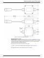
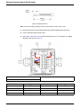
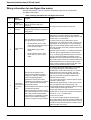
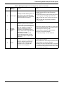
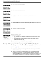
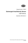
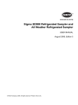
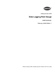
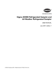
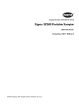
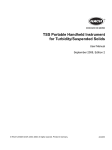
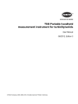
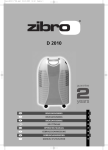
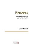
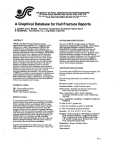
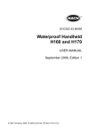
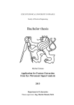
Instruction Sheet
DOC276.53.90025
Universal junction box (4-20 mA input)
Safety information
Please read this entire document before unpacking, setting up, or operating this equipment.
Pay attention to all danger, warning, and caution statements. Failure to do so could result in
serious injury to the operator or damage to the equipment.
Make sure that the protection provided by this equipment is not impaired, do not use or install
this equipment in any manner other than that specified in this document.
Important Note: Indicates a situation which, if not avoided, may cause damage to the
instrument. Information that requires special emphasis.
WARNING
Indicates a potentially or imminently hazardous situation which, if not avoided, could
result in death or serious injury.
Note: Information that supplements points in the main text.
Precautionary Labels
Read all labels and tags attached to the instrument. Personal injury or damage to the
instrument could occur if not observed. A symbol, if noted on the instrument, will be included
with a danger or caution statement in the manual.
Electrical equipment marked with this symbol may not be disposed of in European public disposal systems after
12 August of 2005. In conformity with European local and national regulations (EU Directive 2002/96/EC), European
electrical equipment users must now return old or end-of life equipment to the Producer for disposal at no charge to
the user.
Note: For return for recycling, please contact the equipment producer or supplier for instructions on how to return
end-of-life equipment, producer-supplied electrical accessories, and all auxiliary items for proper disposal.
Overview
WARNING
Possible Explosion Hazard. The sampler connection is not applicable for a
direct connection to flow meters classified for use in hazardous locations
without approved barriers. If the connection is to a flow meter that is classified for, and
used in, a hazardous location, refer to the flow meter control drawing for connection
requirements.
Universal Junction Box
The universal junction box (8760600) gives the necessary interface between an external flow
meter or other device with applicable pulse or current output and the SD900 controller.
This instruction sheet gives:
•
The steps to prepare and connect a universal junction box to a SD900 controller with a
4–20 mA input and to a device with a 4–20 mA output. These connections are required for
flow proportional sampling.
•
The necessary steps to configure the SD900 controller for flow proportional sampling
using the 4–20 mA input.
1
Universal junction box (4-20 mA input)
SD900 4–20 mA input
Pin C of the SD900 controller auxiliary interface can be used as an external pulse input or
as a 4–20 mA input. An external flow meter (such as a Sigma 950) can be connected to
this input for flow proportional sampling.
Note: The 4–20 mA output connector on the Sigma 950 flow meter is a factory installed option
(2676) and comes with a 25 ft. output cable (2924).
The SD900 4–20 mA input removes the need for a separate 2021 or 2020 4–20 mA
interface in flow proportional sampling applications.
Important Note: Do not connect a flow meter that outputs flow pulses on the SD900
auxiliary interface when the sampler is configured for 4–20 mA input.
Pulse Mode
Flow proportional sampling requires an external device with applicable pulse or current
output such as a Sigma 950 flow meter. In pulse mode, each pulse or contact closure
supplied by the external device represents the measurement of a specifed flow-volume.
These signals occur more frequently at higher flow rates and less frequently at lower flow
rates. Numerical scaling is set in the SD900 FLOW SOURCE menu below PROGRAM
SETUP. The SD900 can collect between 1 and 9,999 pulses or closures.
Current Mode
In current mode, a flow meter or external device outputs a current value between 4 and 20
mA to the 4–20 mA input of the SD900. (The current input range for the SD900 is 4–20
mA). The 4–20 mA output is proportional to the measured flow rate. Higher current values
represent higher flow rates and lower current values represent lower flow rates. The
numerical scaling that defines the relationship between the 4–20 mA value and the flow
rate must be programmed the same in both the SD900 and the external flow
measurement device. Numerical scaling is set in the FLOW SOURCE menu under
PROGRAM SETUP in the SD900 controller (see Controller set up for 4–20 mA input on
page 9).
The sampler calculates a flow rate based on the pulse or current inputs. In either mode,
the sampler integrates the flow rate over time to determine an aggregate flow volume.
Samples are taken at programmable increments of aggregate flow.
Important Note: The 4–20 mA option should only be used when an AC power supply is
installed on the flow meter and the SD900. Battery power is not sufficient to support the
4–20 mA current loop power requirements.
Universal junction box
Dimensions
Figure 1 shows the dimensions of the Universal Junction Box.
2
Universal junction box (4-20 mA input)
Figure 1 Universal junction box dimensions
Universal junction box wiring
Important Note: For safety, the universal junction box contains a replaceable 5 mm x20
mm fast-acting fuse (6681000) on the sampler Auxiliary Port line (Pin A). This fuse is rated
at 0.25 A, 250 V and is manufactured by Cooper Bussman (p/n S500-250mA). Do not
rewire the junction box to bypass this fuse.
To wire the universal junction box, complete these steps:
1. Strip 1.5 inches off the customer-supplied cable jacket (Figure 2 on page 4).
2. Strip off 0.2 inches from each cable wire (Figure 2 on page 4).
3
Universal junction box (4-20 mA input)
Figure 2 Prepare the wire
Note: An extra liquid fitting (8783000) can be included when a smaller cable is used.
3. Remove the lid from the universal junction box with a Philips head screw driver.
4. Put the cable through the strain relief.
5. Use Figure 3 and Table 1 to find which terminals to use. For connection to a Sigma
950 flow meter refer to Figure 4.
Figure 3 Universal junction box interior
1
Universal junction box output cable
2
Fuse holder
3
Wiring terminals (refer to Table 1)
Table 1 Terminal assignments
4
Terminal No.
Assignment
Terminal No.
Assignment
1
Fuse
5
Inhibit
2
Power
6
Output
3
Common
7
Complete
4
Input
8
Shield
Universal junction box (4-20 mA input)
Figure 4 Terminal wiring for 950 flow meter
1
To SD900 controller auxiliary connector
3
Output A - (negative) black
OR
Output B - (negative) green
2
4–20 mA output cable assembly (2924)
4
Output A + (positive) yellow
OR
Output B + (positive) red
6. Put the wires in the correct terminals and tighten.
7. Tighten the strain relief on the cable. Do not twist the cable leads.
8. OPTIONAL STEP: Apply the gel potting included with the universal junction box kit to
the inside of the universal junction box to help prevent vibration effects. The gel is not
necessary for junction box installation or use.
To apply the gel, complete the steps below:
a. Twist the static mixer on the gel cartridge.
b. Dispense the gel by using the hand plunger.
c. Discard the first quantity that was dispensed by the static mixer, otherwise it will
not mix correctly.
d. With the junction box flat on a horizontal surface, empty the two gel cartridges into
the junction box until it is filled. Let the gel set for five minutes.
9. Replace the junction box lid and tighten the screws.
5
Universal junction box (4-20 mA input)
Wiring information for non-Sigma flow meters
Use the information in Table 2 to wire the universal junction box for connection to
non-Sigma flow meters.
Table 2 Wiring description for non-Sigma flow meters
Terminal
2
3
Signal
description
Purpose
12 VDC
power output
Power supply positive output. Must be
used in conjunction with pin B
(common).
Common
Power supply negative return. When
using AC power, this pin is connected to
earth ground.
This input triggers sample collection.
The signal may be generated by:
4
5
6
Pulse/Current
input
Liquid level
actuator/auxili
ary control
input
•
An external flow meter or other
device with an appropriate pulse or
4–20 mA control output.
•
Simple floating (dry) contact
closure.
•
An external flow meter or other
device with a 4–20 mA control
output.
This input sends a signal to the
microprocessor inside the sampler
causing it to "wake up" and begin or
resume its sampling program.
Applications for this input include:
A simple float level switch (dry contacts)
may be used to actuate the sampler
when liquid is present.
Start this sampler after another sampler
has finished its program.
Start the sampler in response to some
user-defined condition from an external
device that provides an appropriate
control signal. For example a pH meter
could be used to initiate sampling in
response to a high or low pH condition.
Rating
This output is protected by a 250 mA fuse.
In pulse mode, this input responds to a positive pulse
with respect to Common (pin B). It is terminated
(pulled low) to Common (pin B) through a series 1 kΩ
resistor and 7.5 V zener diode.
In current mode, the input responds to current
entering pin C and returning on pin B (common). The
input burden is 100 ohms plus 0.4 V. The maximum
input current is internally limited at 40 to 50 mA, but
long term operation in this state constitutes abuse and
is not warranted.
Absolute maximum input: 0 to 15 VDC with respect to
Common (pin B). Signal required to activate input:
5–15 V positive going pulse with respect to common
(pin B) of at least 50 millisecond duration. Source
impedance of driving signal should be less than 5 kΩ.
Dry contact (switch) closure of at least 50 millisecond
duration between pin A (12 VDC) and pin C (Pulse
Input). Contact resistance should be less than 5 kΩ.
Contact current will be less than 8 mA DC.
This input is terminated (pulled high) to an internal
+5 V supply through an 11 kΩ resistance and
protected by a series 1 kΩ resistor and 7.5 V zener
diode terminated to Common (pin B). The input
responds to a high to low voltage transition with a
logic low pulse width of at least 50 milliseconds.
Absolute maximum input:
0 to 15 VDC with respect to Common (pin B). Signal
required to activate input:
External logic signal having 5-15 VDC power source.
The drive signal should be normally high. The
external driver should be capable of sinking 0.5 mA @
1 VDC maximum at the logic low level.
A logic high signal from a driver with power source of
greater than 7.5 V will source current into this input at
the rate of: I = (V - 7.5)/1000 where:
I is the source current
V is the power supply voltage of the driving logic.
Dry contact (switch) closure of at least 50 millisecond
duration between pin D and pin B (common). Contact
resistance should be less than 2 kΩ. Contact current
will be less than 0.5 mA DC.
Universal junction box (4-20 mA input)
Table 2 Wiring description for non-Sigma flow meters (continued)
Terminal
6
7
8
Signal
description
Purpose
Rating
Event output
Normally at 0 VDC, this line goes to +12
VDC upon any of the selected events
described in Section 5.3.2 of the SD900
Portable Sampler User Manual.
This output is thermally protected against short circuit
currents to common (pin B). Limit external load
current to 0.2 A.
The output is normally logic low (0 VDC) with respect
to common (pin B). Active high output levels are:
15 VDC nominal when using AC power to power the
sampler
12 VDC nominal when using battery 8754400 to
power the sampler.
Program
complete
output
Normally an open circuit, this line
switches to ground for 90 seconds at
the conclusion of the sampling program.
Used to “wake up” another sampler to
take over sampling or to signal an
operator or data logger upon the
completion of the sampling program.
This pin is also used to signal the bottle
full condition in a single
bottle/continuous mode, and will
transmit the bottle number to a flow
meter if the program complete signal
is disabled.
This is an open collector output with 18 V zener clamp
diode for overvoltage protection. The output is active
low with respect to common (pin B).
Absolute maximum ratings for output transistor:
Sink current = 25 mA DC maximum.
External pull-up voltage = 18 VDC maximum.
Provides connection to earth ground
when the sampler is powered using
AC power. This connection is only
intended for use in controlling RF
emissions and susceptibility.
Not intended for use as safety ground. Do not use as
a current carrying conductor.
Cables greater than 3 meters length connected to the
sampler auxiliary port should be shielded.
Regardless of length, if a shielded cable is connected
to the auxiliary port, the shield (drain) wire should only
be connected to earth ground at one end of the cable
to avoid ground loop currents.
Shield
7
Universal junction box (4-20 mA input)
Connect an external 4–20 mA transmitter
Most self-powered 4–20 mA transmitters have two terminals that float relative to ground.
Connect the transmitter output (+) terminal to the sampler pulse current input (pin 4 of the
universal junction box). Connect the transmitter return (-) terminal to the Common terminal
(pin 3 of the universal junction box). Refer to Figure 5 and Table 3.
Figure 5 Junction box connection for self-powered transmitter
1
Universal junction box
2
Wiring terminals (see Table 3)
3
External transmitter
Table 3 Terminal assignments
Terminal No.
Assignment
3
Common
4
Input
Some 4–20 mA transmitters require an external power source. The transmitter is then
connected between the power output (+) and the sampler pulse current input (pin 4). To
provide a complete current path, the power return (-) terminal must be connected to the
sampler Common (pin 3). Refer to Figure 6 and Table 4.
Figure 6 Junction box connection for external powered transmitter
1
Universal junction box
2
Wiring terminals (refer to Table 4)
3
External transmitter
Table 4 Terminal assignments
Terminal No.
Assignment
3
Common
4
Input
If the transmitter requires an external power source but none is available, power may be
taken from the sampler Auxiliary port (pin 2). However, this may shorten battery life. Refer
to Figure 7 and Table 5.
8
Universal junction box (4-20 mA input)
Figure 7 Junction box connection for SD900 powered transmitter
1
Universal junction box
2
Wiring terminals (refer to Table 5)
3
External transmitter
Table 5 Terminal assignments
Terminal No.
Assignment
2
Power
3
Common (No connection)
4
Input
Controller set up for 4–20 mA input
Controller set up considerations:
•
VARIABLE INTERVALS feature cannot be enabled while pacing using the 4–20
mA input.
•
PROGRAM DELAY using TIME/DATE can be used but PROGRAM DELAY using
COUNTS is not allowed when using the 4–20 mA input.
•
If the user has configured PROGRAM DELAY using COUNTS, the PROGRAM
DELAY is disabled upon selecting the 4–20 mA input as a flow source.
•
OVERRIDE TIME is reset to zero after every sample draw.
To enable flow proportional sampling using 4–20 mA input on the SD900 controller,
complete the steps below:
1. From the Main Menu, Select PROGRAM SETUP, MODIFY SELECTED, SAMPLE
PACING, FLOW BASED.
2. Select 4–20 mA INPUT as the flow source.
3. Select the units used to specify the flow rate while mapping the 4mA and 20mA inputs.
9
Universal junction box (4-20 mA input)
4. Enter the flow rate for the 4mA input.
5. Enter the flow rate for the 20mA input.
6. Specify the total flow volume after which the sample should be drawn.
7. Enable or disable the override time.This is the time after a sample will be drawn even
if the accumulated flow has not reached the total specified in step 6.
8. Specify the override time (if enabled).
4–20 mA Diagnostic Screen
This screen can be used to:
•
view the current value read by the SD900 controller from the 4–20 mA current
loop.
•
view the calculated flow rate based on the current value and the 4–20 mA
mapping provided by the user.
From the Main Menu, select DIAGNOSTICS, 4–20 mA INPUT.
The display shows the input current value and calculated flow rate.
Example of flow proportional sampling using the SD900 4–20 mA option
The following example illustrates flow proportional sampling. A Sigma 950 flow meter with
a 4–20 mA output is connected to the 4–20 mA input on a SD900 through a universal
junction box (Figure 8).
1. Connect the 4–20 mA output of the Sigma 950 to the 4–20 mA input of the SD900.
This forms a current loop.
2. Assume the Sigma 950 is configured to use a V-notch weir at 30 degrees as the
primary device. Configure the 4–20 mA output on the Sigma 950. Set the input
channel as FLOW and map the 4mA output to 9.48 gpm and the 20mA output to 1716
gpm. If the device senses a level of 12 inches, the corresponding flow is 300 gpm.
10
Universal junction box (4-20 mA input)
3. Press RUN/STOP to start the program.
4. Configure the SD900 for 4–20 mA. Set the flow source as the 4–20 mA input.
5. Select the flow units as gpm.
6. Enter 9.48 gpm as the 4mA and 1716 gpm as the 20mA.
7. Below TAKE EVERY SAMPLE, enter 1500 gal. as the total flow value.
8. Configure the remaining parameters and press RUN/HALT PROGRAM and START
the program.
A sample will be drawn every 5 minutes.
Note: This result assumes that the 950 senses a steady level of 12 inches and that an override time
of less than 5 minutes has not been specified.
Figure 8 SD900 to Sigma 950 connection
1
SD900 Auxiliary connector
4
Sigma 950 flow meter
2
SD900 controller
5
4–20 mA output cable (2924)
3
Sigma 950 4–20 mA output connector
6
Universal junction box
11
Contact Information
Repair Service in the
United States:
Authorization must be
obtained before sending
any items for repair.
HACH Company
Tel 1 (800) 635-1230
or (970) 669-3050
Fax (970) 461-3924
[email protected]
Canada, Latin America,
sub-Saharan Africa, Asia,
Australia and New Zealand:
Hach Company World
Headquarters,
P.O. Box 389
Loveland, Colorado,
80539-0389 U.S.A.
Tel 1 (970) 669-3050
Fax 1 (970) 461-3939
[email protected]
Europe, Middle East and
Mediterranean Africa:
Hach Lange GMBH
Willstätterstraße 11
D-40549 Düsseldorf
Tel. +49 (0)2 11 52 88-320
Fax +49 (0)2 11 52 88-210
[email protected]
www.hach-lange.de
HACH LANGE LTD
Pacific Way
Salford
GB-Manchester, M50 1DL
Tel. +44 (0)161 872 14 87
Fax +44 (0)161 848 73 24
[email protected]
www.hach-lange.co.uk
HACH LANGE LTD
Unit 1, Chestnut Road
Western Industrial Estate
IRL-Dublin 12
Tel. +353(0)1 46 02 5 22
Fax +353(0)1 4 50 93 37
[email protected]
www.hach-lange.ie
DR. BRUNO LANGE GES.
MBH
Industriestraße 12
A-3200 Obergrafendorf
Tel. +43 (0)27 47 74 12
Fax +43 (0)27 47 42 18
[email protected]
www.hach-lange.at
DR. LANGE NEDERLAND
B.V.
Laan van Westroijen 2a
NL-4003 AZ Tiel
Tel. +31(0)344 63 11 30
Fax +31(0)344 63 11 50
[email protected]
www.hach-lange.nl
DR. BRUNO LANGE AG
Juchstrasse 1
CH-8604 Hegnau
Tel. +41(0)44 9 45 66 10
Fax +41(0)44 9 45 66 76
[email protected]
www.hach-lange.ch
HACH LANGE FRANCE
S.A.S.
33, Rue du Ballon
F-93165 Noisy Le Grand
Tél. +33 (0)1 48 15 68 70
Fax +33 (0)1 48 15 80 00
[email protected]
www.hach-lange.fr
HACH LANGE SA
Motstraat 54
B-2800 Mechelen
Tél. +32 (0)15 42 35 00
Fax +32 (0)15 41 61 20
[email protected]
www.hach-lange.be
HACH LANGE E.P.E.
27, Avlidos str
GR-115 27 Athens
Tel. +30 210 7777038
Fax +30 210 7777976
[email protected]
www.hach-lange.gr
HACH LANGE APS
Åkandevej 21
DK-2700 Brønshøj
Tel. +45 36 77 29 11
Fax +45 36 77 49 11
[email protected]
www.hach-lange.dk
HACH LANGE AB
Vinthundsvägen 159A
SE-128 62 Sköndal
Tel. +46 (0)8 7 98 05 00
Fax +46 (0)8 7 98 05 30
[email protected]
www.hach-lange.se
HACH LANGE S.R.L.
Via Riccione, 14
I-20156 Milano
Tel. +39 02 39 23 14-1
Fax +39 02 39 23 14-39
[email protected]
www.hach-lange.it
HACH LANGE S.L.U.
Edif. Arteaga Centrum
C/Larrauri, 1C- 2ª Pl.
E-48160 Derio/Vizcaya
Tel. +34 94 657 33 88
Fax +34 94 657 33 97
[email protected]
www.hach-lange.es
HACH LANGE LDA
Av. do Forte nº8
Fracção M
P-2790-072 Carnaxide
Tel. +351 214 253 420
Fax +351 214 253 429
[email protected]
www.hach-lange.pt
HACH LANGE SP.ZO.O.
ul. Opolska 143 a
PL-52-013 Wrocław
Tel. +48 (0)71 342 10-83
Fax +48 (0)71 342 10-79
[email protected]
www.hach-lange.pl
HACH LANGE S.R.O.
Lešanská 2a/1176
CZ-141 00 Praha 4
Tel. +420 272 12 45 45
Fax +420 272 12 45 46
[email protected]
www.hach-lange.cz
HACH LANGE S.R.O.
Roľnícka 21
SK-831 07 Bratislava –
Vajnory
Tel. +421 (0)2 4820 9091
Fax +421 (0)2 4820 9093
[email protected]
www.hach-lange.sk
HACH LANGE KFT.
Hegyalja u. 7-13.
H-1016 Budapest
Tel. +36 (06)1 225 7783
Fax +36 (06)1 225 7784
[email protected]
www.hach-lange.hu
HACH LANGE S.R.L.
Str. Leonida, nr. 13
Sector 2
RO-020555 Bucuresti
Tel. +40 (0) 21 201 92 43
Fax +40 (0) 21 201 92 43
[email protected]
www.hach-lange.ro
HACH LANGE
8, Kr. Sarafov str.
BG-1164 Sofia
Tel. +359 (0)2 963 44 54
Fax +359 (0)2 866 04 47
[email protected]
www.hach-lange.bg
HACH LANGE SU
ANALÝZ SÝSTEMLERÝ
LTD.ÞTÝ.
Hilal Mah. 75. Sokak
Arman Plaza No: 9/A
TR-06550 Çankaya/ANKARA
Tel. +90 (0)312 440 98 98
Fax +90 (0)312 442 11 01
[email protected]
www.hach-lange.com.tr
United States:
Hach Company
P.O. Box 389
Loveland, Colorado
80539-0389 U.S.A.
Tel 800-635-4567
Fax (970) 461-3919
[email protected]
www.hach.com
Hach Lange EU subsidiaries:
© Hach Company, 2008. All rights reserved. Printed in the U.S.A.
Edition 1 January 2008 kw/kt