1
THE SOCIETY OF NAVAL ARCHITECTS AND MARINE ENGINEERS
601 PsvonlaAvenue,Suitem, JerseyCity,NewJersey 07306 USA
Mahhnance,
and Mnituring $ympmium
F- prasan~at h Marirs Sbmumal ln~al,
Shwatca Naliord Hotel,Arlingtan.Wginia, Mardi l&19, 1%1
A Graphical Database for Hull Fracture Reports
J. Letcher and D. Shook,
D. Sucharsld,
‘,
Aerohydro Incorporated, Southwest Harbor, Maine
Arco Marine, Inc., Long Beach, California
ABSTR4CT
SYSTEM IMPLEMENTATION
HFDB is the Hull Fracture Databases
stem,
implemented b AeroHydro, Inc. (A & for ARCO
Marine, Inc. (A h ). The purpose of H A B is the
establishment, maintenance, and utilization of a
aphics-oriented database of structural fracture data
!?om the AMl fleet of crude oil tankships. HFDB takes
its primary input from a graphics tablet, allowing
fracture locations to be conveniently entered from
fracture report sheets supplied as part of thes stem.
Graphics tablet menus are used for auxili
ata
input. Graphic screen displays are provideTz during
input to visually verify the input data. The data is
stored in a Paradox database suited to selective
retrieval. Graphical output displays show locations,
frequenq of occurrence, and severity of fractures as a
function of ship name, ship class, time interval,
structural element, and severity. The overall purpose
of HFDB is to enable a human operator to discern and
explore patterns of fracture experience, which may
lead to improved design, maintenance, and ins ection
procedures and to reduced risk.of structural fa Tures
m the future operation of the fleet.
The core of HFDB is im lemented as a Paradox
A lication Language b AL pro~am. This rogram
c3 s com iled programs written u-tMicroso i
QuickBA~IC to perform graphical functions not
conducive to implementation with PAL. These
auxiliary programs return to the PAL ro am when
their functions areco~lete.13ecause
he~acture
database is a Pmadox
atabase, all of the analysis and
re orting ca abilities of Paradox are available in
a 2 dltion to t[ e capabilities provided by HFDB. In
addition, the data cam be exported from Paradox for
use by other an’klysis programs.
THE FRACTURE DATABASE
The mison d’efre of HFDB is the fracture database. The
fracture database contains one record for each
fracture.
The following information
fracture:
FR serial number
NOMENCLATURE
FRS - Fracture Report Sheet
FR - Fracture Report
~~~
HFDB - Hull Fracture Database
DESIGN GOALS
Fracture number
is recorded
for each
- Fracture Report serial number
- within fracture report
FRS number- identifies the fracture report sheet
from which the data was entered
Ship - Indqendmce,
Spirit, Aladm, California,
Anchorage, Fairbanks, Juneau, Texas, Prudhoe Eay,
Sag River
Cla~O-&O~WT, 190MDWT, 120MDWT, 90MDWT,
It is anticipated that HFDB will be used over a lon
period of time. Provisions are specifically include f to
allow handling of fractures thou h 205 . It is also
anticipated that the program will L] -used by eople
such as summer interns who have never use t the
pro~am before. For this reason the system has been
des~gned to be as fool roof as possible. The complete
user manual is accessl‘zle as a hypertext document by
pressing a functionkey while usm the ro~arn. In
addition there is a complete tutonN , mc udmg
sample in ut data and database,. that a new user can
follow to 1!ecome familiar with thes stem without
jeopardizing the actual fracture data I ase.
X - Feet, O at F.P., positive aft
Y- Feet, Oat centerline, positive to starboard
Z - Feet, O at baseline,
Severi~
-<3”,3’-6”,
positive
upwards
6“-12”, 1’-2’,>2’, Thru
Member - Web Frame Plate, Web Stiffener, Bulkhead
Plate, Bulkhead Stiffener, Lon “tudinal Girder
Plate, Longitudinal Girder StI# ener, Shell Plate,
F.B. Tie Bar, Lon “tudinal, Bracket, Strut, Face
Plate, Horizont a?’Grder Plate
Disposition - Repair, Modify, Renew
A $oal of the system is to make it easy to enter data.
Tlws is im ortant because if it is not easy, it may very
Year repaired
likely not \ e done.
Date entered
F-I
view is a schematic profile
oftheshipwiththe
longitudinal
locations
ofthestructures
illustrated.
“rder
FRS’Shave a second my
Genericlongitudinal
drawing which is a scE ematic section. There are’no
generic centerline girder FRS’S.
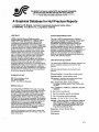
FRACTURE REPORT SHEETS AND FIViCTURE
REPORTS
Input to HFDB is initially entered b a ship ad
surveyor on a pa er form called a 1?racture K,,.*
Sheet (FRS). An FRS is an 8.5” x 11” form with a
drawin of a particular structure in a particular class
of ship.% hen a shipyard surve or finds a fracture, he
or she chooses from the set of Fi S’s for the class of
ship being surveyed the FRS whose main drawing
shows the location of the fracture. An FRS also has
boxes on which the surve or must checkoff the ship
name and date. Some FRJ s also have a second
When using a generic FRS (an FRS with a auxiliary
view), the surve or must mm 1 the auxili ~ewto
ufiquely ident’& the structure within thes “p.
The surve or must mark the primary drawin of the
FRS with L th the-location and the severity.. A e
location should be marlwd with an “X’. The severity,
positioned adjacent to the “X, should indicate the size
of the fracture in feet and inches, or “Thru” if the
fracture is all the wa throu h the structural member.
+ more than one fracture,
An PRS ma be mar 1 ed wlt
as long as t{ e fractures are for the same ship, year
and, in the case of generic FRS’S, structure.
drawing (described below). There are currentlyY“ve
FRStypes:
(1)
(2)
(3)
(4)
(5)
.. . .--
Bulkhead
Web Frame
Bulkhead/Web Frame
Centerline Girder
Longitudinal Gkder (off-center)
When a blank FRS has been filled out, it becomes a
Fracture Repofi (FR). When the FR is entered into the
HFDB system (in a process described below), an FR
A particular FRS may be “unique” or “generic.” For
instance, a bulkhead FRS for a bulkhead in the
parallel midsection of a ship would be generic: the
same FRS would be used for an of the several
identical bulkheads in the paral Tel midsection. A..
bulkhead FRS for a bulkhead in the forward tapered
serial number is assl ed to it and written by the data
entry operator into R e space provided on the FRS.
section of the ship would be unique.
Generic FRS’S have a second
schematic drawing
al ows the FRS to be
(the “auxiliary view” which Y
located in the ship. 2 or a eneric bulkhead, web
frame, and bulkhead/we %frame FRS, the auxiliary
Imll, !
L.7
,.
ID
! ! !“! ! ! ! !.7!, ! I
I
I
I
I
I
I
I
I
I
I
I
I
I
I
I
I
I
I
-1
LI
Wz
1.11
.,
-12
LIZ
.11
I
1
11
1
w
-1
1
1
I
1
1
1
I
I
I
H:
1
l.?
El
14
Wn
lwll—
Yr.
L-*
m
02
::::
-11
M.,4
v 1]
I
“.9
.1
L.1
I
4
4
El
u,,
03
El
1
04
,
06
L“,”
0s
L.
w
07
08
L
L’
~
F
+
120 MOVT
O.T.
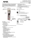
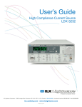
Fig. 1. A -“c
F-2
g
BHD FR. 61. 73.
pm
Fm#lm
:
09
‘
81
bulkhead jw?cture report sheet with a profile muiliny
vimu.
.,/
At I
r
I
\
Alaska>
]Call
Fornla
I
I
I
a
FRS,
No.?I?
1+
Decade
Bo
E00
10
20
30
i 40
ia
El
—lm?Plmmm
04 L.li
Clrnl
3
0
o
000
a.
x
0
a
0
0
Y
000
000
11
~’
“
ti.L,
000
n
a
a
GMXRU$
115.,’
hll
1,
#FCL
,1
H
b
A
00
0
000
Yr,
~
01
02
a
a
w,
24
ZJ
03
04
I
05
~
C.L. I
L.11 I?S’.V
W
C,L I
M
Ull
fl
[.L’. I
W
CL I
07
I!4W
L-21 IH’.I’
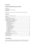
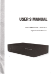
190 hDVT INMR WTTOM LD4G‘L. GIRDERS
NO. 1 CAffiOTAM
00 ‘o:
CM
0000
I 09
+
‘\
Fig. 2. A -’c
ofl.center lon~”tudinalfiatiure
re@.
THE HFDB PROGRAM
HFDB is a menu driven program. fie main, top level
menu provides access to the three principal functions
of interest here:Data entry
Data selection
Display
The main menu also rovides access to utili
functions such as bac “n up and restorin tY e
fracture database and‘fde eting erroneous E acture
records.
IVotice that th transver~
a~”liay
vietu has been marked.
user clicks an inactive button or an inactive area of
the tablet, a longer, lower-pitched tone indicates that
the click was not effective.
The first step of the data en~ procedure is to register
the Permanent Form containing the buttons that need
to be permanent
available during the tablet data
entry procedure. ; lgure 3 shows the Permanent Form.
TIIle~rg -am needs the registration information in
% ow the position of the Permanent Form on
the tablet. The rogram rompts the user to click two
bulk+eyeslabe~d A an?13.
HFDB then prom ts the user to mount a Fracture
Report on the tab Fet and register it by clicking bullseyes labeled C, D, E, and F on the four comers of the
form.
Tablet Data Entry
The data entry procedure is operated almost entirely
through selections made on the graphics tablet.
Smeen prompts and displays are used to
ide. the
recess and to confirm selections before ey are
~nallyaccepted.
:
‘
Following registration, HFDB prompts for
identification of ship, decade, year, and FRS b
clicking appropriate marked buttons on the d . These
can be entered in any order.
Tablet selections are made by clicldng the tablets
or tablet mouse (button 1) vnthin labeled rectan J
areas on the tablet forms which are referred to as
‘buttons.”
As noted above, an FRS may be uni ue or generic. On
a generic FRS, the operator must clic1 the stylus on
the surveyor’s mark on the auxilimy view which
allows the pro er structure to be uni~uel identified.
On a urdque FR S, this step is not requmeJ .
lus
ar
The availability of various button? is controlled by the
program, so that ordy an a
acdveatanygiventune.
LflK%S’%fL%I%g~is
button, the computer makes a short, high- itched
beep to confirm the selection is understoo ! . If the
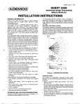
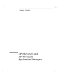
Next, HFDB displays the fracture en~ screen. Figure
4 shows an example. Most of the screen is taken up
with the structural drawing. Below the drawing are
several labeled lines containing blanks where fracture
data will be filled in.
F-3
SEVERITY
STRUCTURAL
MEMBER
~..;
.
~-.,~~H 1..2,
SIrul
longl
Girder
Xtfnr
~
-r+.
YN
THRu
Plow
I 10IIOIGirder
~~m=
~
)2’
H
ZDDH
New Fracture
DISPOSITION
Repnlr
Hodify
Renep
Return
Report
to Menu
Fig. 3. The HFDB Permunent Form.
M
m
c
+wlllll
mill’
L-M I I
‘n
—...
.90 ~T
Rcquiring
data.
forfracture
recurdno. 1
Structura
1 tledmr: Web Frame Plate
3“-6”
Sever itg:
Locat icm: H “720.5
Corflmnt:
Whatmm
Fix:
flepair
-77.~
z
Y
cunment
64,5
Ship: RIaska
FRS HOi
FR Bate:
FR Serial
206
1990
No.
1
YOUentered
Fig. 4. HFDBfracture enty xreen.
Log “ g a fra~ealways
requires entry of at least
the Pollowing information:
(1)
(2)
A shmctural member selected from the
permanent form
$=9
level selected from the permanent
(3)
A location on the structural drawing
The following items are-optional:
(4)
A Fix selected from the permanent form
(5)
(Repair/Modify/Renew);
A text comment
the default is “Repair”
All these items may be entered in any order and can
be re-clicked as many times as necessary. As each is
entered, it is diiplaYed in the appropriate location on
the screeu for confmnation.
F-4
A aphics cursor in the drawing area of the screen
WI‘f track the tablet stylus when the stylus is in the
drawing box. Clicking the stylus leaves a bri ht green
X on the screen at the cursor location. These Fected
coordinates are echoed in the text area of the screen.
~s is the tentative location of the fractur% it can be
corrected by re<licking. When the user accepts the
fracture record, the green X changes to red.
The user clicks the <ACCEPT> button to confirm that
the fracture has been entered correctly. HFDB is then
read y to accept another fracture from the same FR. If
all the fractures have been entered, the user can click
the cNew Fracture Report> button or the <Return to
Menu> button to end the data entry session.
Data Selection
“\
Dataanalysis
withHFDB involves first selecting a
subset of the data and then displaying that subsef in
any one of three forms.
HFDB provides a-selection screen on which the user
may make selections based on ship, class, sh-ucture
fractured, severity, and date. The selections are made
by usin~ the cursor control ke s to move to the
desired item tid then highlig i ting the item”by
pressing the s~acibar. In this manner it is eas to
make a selechon such as “All fractures on AZasL or
Cdj%Ih
Which Were discovered
~ 19s$J or 1990.’”
his also possible to select a single FR b its FR serial
number or to select all frames which i’ ave been
entered on a particular FRS by using the three digit
FRS number.
For ex erienced Paradox users, there is a revision to
enter $ aradox, make a selection using all i e
ca
abilities
of the Paradox
uery mechanism,
thes~ectedsu~set.
return
to!IFDB, arid display
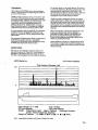
Graphic Displav
The second display is the profile display. This shows
a schematic profile of a slup below a stacked bar chart
re resenting the longitudinal distribution of the
ser“’”
ected fractures. Each bar is color coded to represent
the occurrence of each severity. There is also a
desqip.tion of the current selection criteria.
While the profile is dis layed, the user can use the
cursor control ke s to c oose one or more subsets of
the longitudinal i%ars and then display those selected
fractures in section view, with a color coded dot for
each fracture Wd two stacked bm charts showing the
athwartship and vertical distributions of the selected
fractures.
While viewing each “ofthese three displays, the user
may press a function key which will cause a
presentation quali version of the display to be
rinted b an a~ac? ed PostScript laser printer.
~{everal o these displays are included below in the
section on preliminary results.
Also available is a display of a single fracture report.
This displa is similar to the data en~ display and
can be use J to confirm that a fracture report has been
entered correctly.
The user can now displa the selected subset. The
simplest dis lay is the
histogram oF the selected
fracture records
vs. tune.
“3mep10t”
‘fichdisp!aysa
The bars of the histogram are color coded for severity.
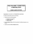
ARCO Marine Inc.
Hull Fracture Database
\,
Total Number of Fractures: 346
50
R
0
1
Date of Report: 12-11-1990
Time: 15:29:30
FR: None Selected
FRS: None Selected
Ind&pendence Spirit
Alaska California
Ship(s):
Anchorage Fairbanks
Juneau Texas Prudhoe Bay Sag River
‘D <3”~ 3“-6” ■ 6“-12U ■ 1‘-2’ ~ >2’ H THRU
Class(s) of Fracttires:
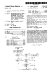
Fig. 5. Longitudinal distribution offrucfures
of
Alnskx Class ships.
F-5
PRELIMINARY RESULTS
ARCOMarine Inc. isusin I-IFDBto monitor and
assess hull fractures inits i eetoften crude oil tankers
in the Alaska to W& Coast tiade. Use of the database
focuses ARCO’Sfracture, control efforts which include
inspections, analyses, aid modifications. Better focus
ensures better use of available resources for these
tasks, which in turn reduces the risks of undetected
fractures and of failure to understand. the cause and
to effect successful remedies.
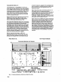
Figures 5 ancl 6 show the lon “tudinal and transverse
distributions of fractures in t.”e two ships of the
ARCO Alaska Class (190,000 dwt). These lots are
based on 346 fractures detected since 19d.
The longitudinal dis~bution shows the concer&ation
of fractures at the transverse bulkheads and especially
the wing ballast tarikbukheads. The transverse
distribution shows that the.fractures are concentrated
at the ship’s side in the lower half of the shi ‘s de th.
This distribution is contrary to anecdotal 1# o~a !i on
which suggests that fracturing is more common in the
upper part of the ship; Although a slightly greater
irmdence of fracturin~ is recorded for the starboard
side, the difference with respect to the port side is not
at great as anecdotal information suggests.
as shown in Figure 6, suggests other possibilities. me
need for anal sis of the structure near the ship’s sides
between the Yth and 14th longitudinal above the
baseline is evident.
F@re 6 also shows the concentration of fractures at
the vertical level of the transverse bulkhead
horizontal ‘rders. lt is evident that these fractures are
most prev J? ent at the intersections of the horizontal
‘rders and the ship’s sides tid longitudinal
F ulkheads. Analysls of”the structure in these locations
could lead to a better repair which would prevent the
reoccurrence of the common fractures.
.. . .
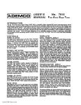
Figure 7 shows how HFDB can be used to identify the
e 7 is the s~e
type of shpcture which is failing. Fi
transverse, view shown in Figure 6, P ut shows only
fractures m flatbar tie plates. Similar plots can be
made for each shuctural type, and a com arisen of
these plots with Figure 6 can be used to i$ entify the
Peor”Tofsti-eswtich”~a*~
em Iota ens. The success of moduicahons‘well%
over bme
can also be determined by accessing only fractures in
modified structures. These techniques gwe ARCO an
increasingly Wter understandin~ of the fractures in
its shi s and improve the probabdi~ of successful
reme Cfies.
Based on anecdotal information, ARCO had
ostulated that the cause of the fractures was wave
roads in the loaded voyage on the weather side. The
focused, more complete view of the fracture record,
ARCO Marine Inc.
Hull Fracture Database
.
Transverse Distribution of Fra&tures
50,
1 1
i
E+
Vertical
Distribution
o
o
Date of Report: 12-11-1990
Time: 15:30:35
FR: None Selected
FRS: None Seleoted .,
Ship(s):
Independence Spirit
Alaska .California
Anchorage Fairbanks
Juneau Texas Prudhoe Bay Sag River ~
Class(s) of Fractures:
El <3’W 3“-6” ~ 6“-12“ 91 ‘-2’ ■ >2’ ● THRU
Fig. 6. Trunsoersedisti”butionoffractures ofAlaska Classships.
F-6
80
ARCO Marine Inc,
Hull Fracture Database
Transverse Distribution of Fractures
Vertical
Distribution
o
LOOK
I
NG
FORWARD
■
■
m
-..
I
■
1
10
.
—
Date of Report: 12-11-1990
Time: 16:10:50.
FR: None Selected
FRS: None Selected
Ship(s):
Anchoraae Fairbanks
Independence S~irit
Alaska California
.
Jun~au Texas P~udhoe Bay Sag River
THRU
❑ <3”H 3“.6” ■ 6“-12“ ■ 1‘-2’ H>2¤
Class(s) of Fraotures:
~.
Fig. 7. Trnnsoersz distribution offructures injldbm
tie plates of Alnsb
Class ships,
F-7