1
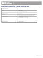
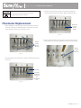
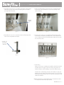
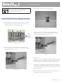
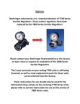
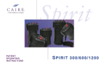
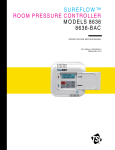
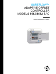
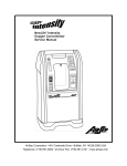
SureFlow™
Oxygen Flow Station
PROVIDER TECHNICAL MANUAL
Table of Contents
Definition of Product Symbols................................................... 3
General Information.................................................................... 3
Warning and Caution Statements....................................................................3
Introduction to the SureFlow Oxygen Flow Station................. 4
Specifications .............................................................................. 5
Flowmeter Replacement............................................................. 6
Leak Testing....................................................................................................................7
Inlet/Outlet Valve Replacement................................................. 8
Leak Testing....................................................................................................................8
Cleaning........................................................................................ 9
Oxygen Flow Station Provider Technical Manual
Definition of Product Symbols
Symbol
General Information
Definition
Warnings and Cautions
Warning and Caution Statements
Safety instructions are defined as follows:
No serviceable parts inside. Do not open cover.
WARNING:
Refer to the instructions or manual from the oxygen
source manufacturer for all warnings, cautions and
notes that may be applicable.
WARNING:
Oxygen promotes rapid burning. Do not allow
smoking or open flames in the same room where
oxygen is being used.
Do not expose to open flames
No Smoking Icon: Do not smoke near unit.
Complies with the 93/42/EEC directive drawn up by
the approved organization No. 0459
Use no oil or grease.
Read user manual before operation. See user manual
for instructions.
This symbol is to remind the equipment owners
to return it to a recycling facility at the end of its
life, per Waste Electrical and Electronic Equipment
(WEEE) Directive. Proper disposal of waste of
electrical and electronic equipment required.
WARNING:
If a SureFlow outlet is not in use, the flowmeter must
be turned to 0.
CAUTION
The oxygen source must not exceed 20 psig (138 kPa)
Name and address of manufacturer
Authorized representative in the European
Community
PN MN155-1 B — 3
Oxygen Flow Station Provider Technical Manual
Introduction to the SureFlow Oxygen Flow Station
SureFlow™ is a uniquely engineered flow station developed by AirSep®
Corporation for economically administering medical-grade oxygen to
multiple patients from an oxygen concentrator or other oxygen source
(gas or liquid).
This product enables clinicians and medics around the world to
manage and redirect the flow from a single oxygen source to a simple
flow station to serve up to five individuals per SureFlow unit.
Two or more SureFlow units can be connected together to serve even
more individuals simultaneously. Each flowmeter is adjusted separately
to ensure precise control with a visual indication of flow for safety and
comfort.
Dual flow models of NewLife® Intensity 8 and 10 LPM concentrators
provide greater flexibility in delivering oxygen by allowing SureFlow to
operate connected to one of the concentrator’s flowmeters while the
secondary flowmeter can supply oxygen for a nebulizer treatment or a
higher flow patient.
SureFlow units also meet the low flow oxygen needs of pediatric
patients in a critical care nursery in developing countries around the
globe. The standard SureFlow is configured with 5 low flow flowmeters,
which display in 0.10 increments, and can be used in a wide range of
settings from 0.10 to 1.0 LPM. SureFlow can also be specially ordered
with a combination of 1 LPM and 5 LPM flowmeters, or with five 2 LPM
flowmeters which display in 1/8 LPM increments.
The SureFlow is a simple device that will not require a regular service
schedule.
Two procedures, one for flowmeter replacement and one for inlet
valve replacement, are included in the unlikely event that a repair is
needed. The flowmeter or inlet/outlet valve may need replacement if it
becomes damaged, or begins to leak.
PN MN155-1 B — 4
Oxygen Flow Station Provider Technical Manual
SureFlow Oxygen Flow Station Specifications
Dimensions (W x H X D)
Weight
9.7 in. W x 5.8 in. H x 7.2 in. D
(24.6 cm W x 14.7 cm H x 18.3 cm D)
3.28 lb (1.49 kg)
5.6 lb (2.5 kg) — Shipping Weight
Maximum Inlet Pressure
20 psig (138 kPa)
Flowmeters
Low flow flowmeters can be used from 1/10 LPM to 1 LPM with
.1 LPM increments with back lines for proper viewing angle.
Flowmeter Accuracy
0-1 lpm Flowmeter ± 3% of Full Scale
0-2 lpm Flowmeter ± 5% of Full Scale
0-5 lpm Flowmeter ± 5% of Full Scale
Operating Temperature
5 - 40°C (40° - 104°F)
Storage Temperature
-5° - 60°C (30° - 140°F)
PN MN155-1 B — 5
Oxygen Flow Station Provider Technical Manual
CAUTION
3. Loosen and remove the pal nuts and retaining bracket that
secure the flowmeter to the cabinet. Remove the flowmeter.
Disconnect from any oxygen source before
attempting any service or repair.
Flowmeter Replacement
Remove pal
nut and
retaining
bracket
1. With a Phillips head #2 screwdriver, remove the three screws in
the back of the device. Pull the bottom of the back cover out,
then rotate up and away to remove the cover.
Figure 3
Remove
3 screws,
then the
rear cover
4. Cut the heads off of the tie wraps that are on the two pieces of
tubing that you previously cut. Remove and discard this tubing.
Remove
tie wraps
and tubing
Figure 1
2. Cut the tubing to the inlet and the outlet of the flowmeter to be
replaced.
Figure 4
Cut Tubing
Cut tubing
between the
barb fitting
and
the flowmeter
inlet
Figure 2
PN MN155-1 B — 6
Oxygen Flow Station Provider Technical Manual
5. Assemble the 8½ inch (21.6 cm) tube to the barb on the product
outlet that you just removed the old tubing from and install a
tie-wrap behind the barb.
7. Fit the new flowmeter into the desired slot. Assemble bracket
and pal nut on the flowmeter to secure the assembly to the
cabinet housing.
New 8½”
tubing
Figure 5
6. Assemble the 1¼ inch (3.2 cm) tube to the new flowmeter inlet
valve and tie wrap behind the barb.
Figure 7
8. Connect the 1¼ inch (3.2 cm) tube from the flowmeter (inlet)
to the barb on the tubing assembly. Next, connect the 8½ inch
(21.6 cm) tube to the top of the flowmeter (outlet) and tie wrap
all connection points.
Assemble 1¼”
tube to flow
meter inlet
Figure 6
Figure 8
9. Leak Testing
After any servicing is complete, the SureFlow should be checked
for leaks, Attach to oxygen source and using soapy water or a
leak test solution, check all tubing connections before closing.
Another aid in determining the source of a leak(s) is to put your
thumb over each outlet at the SureFlow station, on at a time. The
flowmeter ball must drop to zero on each test, indicating no leak
within the SureFlow.
10. Replace the back cover after leak testing, and use three screws
to complete the flowmeter replacement.
PN MN155-1 B — 7
Oxygen Flow Station Provider Technical Manual
CAUTION
3. Apply Teflon tape to the new inlet/outlet valve.
Disconnect from any oxygen source before
attempting any service or repair.
Inlet/Outlet Valve Replacement
1. With a Phillips head #2 screwdriver, remove the three screws in
the back of the device. Pull the bottom of the back cover out
then rotate up and away to remove the cover.
Figure 11
Remove
3 screws,
then the
rear cover
4. Using two wrenches hold the inner nut in place with one
wrench (7/16 inch [1.1 cm]) and screw in the outer nut of the
valve with the other wrench (5/8 inch [1.2 cm]).
Figure 9
2. Using two wrenches, hold the inner nut in place with one
wrench (7/16 inch [1.1 cm]) and unscrew the outer nut with the
other wrench (5/8 inch [1.2 cm]).
Figure 12
5. Leak Testing
After any servicing is complete, the SureFlow should be checked
for leaks. Attach to an oxygen source and using soapy water or a
leak test solution, check all tubing connections before closing.
Another aid in determining the source of a leak(s) is to put your
thumb over each outlet at the SureFlow station, on at a time. The
flowmeter ball must drop to zero on each test, indicating no leak
within the SureFlow.
Figure 10
6. Replace the back cover after leak testing and use three screws to
complete the inlet/outlet valve replacement.
PN MN155-1 B — 8
Oxygen Flow Station Provider Technical Manual
Cleaning
Do not use abrasive powders or chemicals. Clean only the exterior of
the SureFlow unit, which can be disinfected with either a common
chemical disinfectant or a diluted solution* of household bleach
(sodium hypochlorite 5.25%). To use effectively, mix a solution of
1:100 parts of bleach to water. Wear eye and skin protection and allow
the solution to remain on the surface for 10 minutes. After using the
disinfecting solution, rinse with water and wipe dry. Make sure unit is
completely dry and then retest it before you return it to inventory.
*The manufacturers of sodium hypochlorite products recommend various strengths of a
bleach solution for killing bacteria, etc., based on the type of germ to disinfect; however,
a generally recommended solution is ¾ cups (237 ml) of household bleach per gallon
(3.79 L) of water.
PN MN155-1 B — 9
Oxygen Flow Station Provider Technical Manual
CAIRE Inc. Customer Service Contact Information
If you need any additional assistance, contact CAIRE Inc:
By mail:
CAIRE, Inc.
2200 Airport Industrial Drive, Suite 500
Ball Ground, GA 30107 USA
By telephone: 800.482.2473
By E-mail: [email protected]
www.CAIREmedical.com
Authorized European Union Representative:
Medical Product Services GmbH
Borngasse 20
35619 Braunfels, Germany
E-mail: [email protected]
www.CAIREmedical.com
AirSep®, NewLife®, and SureFlow™ are registered trademarks of CAIRE Inc.
Copyright © 2014 Chart Industries. CAIRE Inc. reserves the right to discontinue its products, or change the prices,
materials, equipment, quality, descriptions, specifications and/or processes to its products at any time without prior
notice and with no further obligation or consequence. All rights not expressly stated herein are reserved by us, as
applicable.
PN MN155-1 B — 10