1
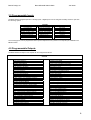
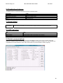
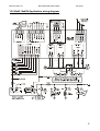
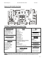
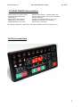
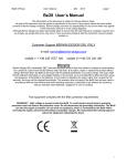
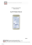
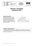
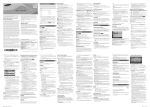
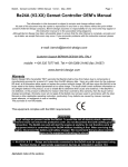
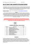
Bernini Design srl
Be42 & Be42N Sales bulletin
Jan./2009
Be42 & Be42N
AMF + ATS + Engine Controller
Sales bulletin
www.bernini-design.com
Summary
1.0 Description
2.0 State of the art design
3.0 Programmable Inputs
4.0 Programmable Outputs
5.0 Display features
6.0 Pushbuttons features
7.0 Speed detect
8.0 LED indicators
9.0 Serial communications
10.0
11.0
12.0
13.0
14.0
Application wiring diagram
Front fascia
Programmable parameters
Characteristics
Front Panel view
1.0 Description
The Be42 (or Be42N) is 3-phase A.T.S. controllers & Generator monitoring systems. Its programming runs quickly,
and all parameters, alarms and operating functions are indicated by means of a high-luminosity display capable of
operating in a temperature range between -30°C and +70°C. The Be42 interfaces with resistive sensors up to 2000 Ohm.
Measurements including Vac, Aac, Vdc, Hz, hour count, R.p.m., Oil Pressure, Engine Temperature, Battery Vdc (Engine)
and Fuel Level. A Windows XP © compatible remote monitoring and control software program is also provided. The
Be42 provides RS485 MODBUS. Be42 complies with NFPA-110 / NFPA-99 specifications. The version Be42N (without
Sensor inputs) allows you to save money in case the engine is equipped with switches instead of sensors (Oil /
Temperature & Fuel) .
© Windows and Excel are registered trademark of Microsoft Corporation
2.0 State-of-the-art Innovative features
- RS485 & MODBUS protocol, RS232 converter available on request
- 4-digit Led-Display operating between -30° and +70°
- Interfaces with 3 Resistive sensors up to 2000 OHM (Bar / °C / Fuel%)
- Low cost version Be42N (without input sensors) available on request
- Aac, Vac, Hz, Vdc, Charger Vdc, RPM-meter & h-meter
- 26 Options for each programmable input & 59 Options for each Output
- 8 digital Inputs, 9 digital Outputs and 3 Sensor Inputs
- High quality manufacturing, 72-hour dynamic burn-in, 3-Year warranty
- High luminosity Display indicating 40 alarms or Status messages
- More than 180 programmable parameters, password protected
1
Bernini Design srl
Be42 & Be42N Sales bulletin
Jan./2009
3.0 Programmable Inputs
The Be42 features 8 digital inputs and 3 analog inputs. 4 digital inputs can be configured normally closed or open with
the following options:
Disable input
Immediate Stop
Bypass and Stop
Cooling and Stop
Bypass + Cooling + Stop
Warning only
Bypass and Warning
Remote Manual Mode
Remote Auto Mode
OPTIONS
Remote LOCK
Generator simulation
Mains Simulation
Remote LEDs test
Remote Acknowledge
Display Control ←
Display Control →
KG feedback
KG feedback
Remote Off Mode
Idle Speed
Engine Test
Genset test
KM Control
KM Control
Overload
The 3 analog inputs, can be programmed with a 6-point response curve by means of a computer (not available in the
BE42N version.
4.0 Programmable Outputs
The Be42 features 9 outputs. Four outputs can be configured as follows:
OPTIONS
The Output is disabled
Under Speed Shutdown
Over Speed Shutdown
Common Speed Alarms
Under Frequency Shutdown
Over Frequency Shutdown
Over Current Shutdown
Over Current Warning
Over/Under Voltage Shutdown
Alternator Failure Shutdown
Maintenance SERVICE 1,2 and 3
Auxiliary Alarm 1-2-3-4: Shutdown / Warning
Common Generator Alarms
Low Oil Pressure Warning or Sensor Failure
Low Oil Pressure Shutdown (Sensor/Switch)
Common Oil Pressure Alarms
High Temperature Shutdown
High – Low Temperature Warning (Sensor)
Common Temperature Alarms
High – Low Battery Voltage Warning
No Fuel in Tank Shutdown
Low Level Fuel Warning
Fuel Reserve Warning
High Fuel Warning
Fuel Sensor Failure Warning
Common Fuel Alarms / Sensor Failure
Panel Stop Shutdown
Common Input Alarm
Presence of Nominal Mains Parameters
Presence of Nominal Generator Voltage
Mains Failure Timing
Mains Restore Timing
KG Contactor of the GENERATOR Closed
KM Contactor of the MAINS Closed
Crank Delay (Start Warning)
Pre-glow ACTIVATED
PURGE (gas engine valve control)
Engine Running Status
Cooling Timing
Warm up Timing
RENT Warning(<48h )/Shutdown (Expired)
BE42 in OFF MODE (Status)
BE42 in MANUAL MODE (Status)
BE42 in AUTO MODE (Status)
BE42 in TEST MODE (Status)
BE42 in LOCK MODE (Status)
Automatic Periodic Test
Fail To START Shutdown
Fail To STOP Shutdown
Engine Belt Break Shutdown
Indication of Parameter Error warning
Idle Engine
Clock Error or Periodic Test Error
Control for Reserve Generator
2
Bernini Design srl
Be42 & Be42N Sales bulletin
Jan./2009
5.0 Display features
The Be42 features 4 high-luminosity displays , to indicate the following:
- Electrical measurements
- Menu and sub Menu
- Alarms & Messages
5.1 Display: alarm indications
OVER/UNDER FREQUENCY (SD)
OVER/UNDER VOLTAGE (SD)
- Engine parameters / measurements
- Programming
- Miscellaneous parameters
The Be42 monitors the following alarms:
LOW OIL PRESSURE (SD)
LOW OIL PRESSURE (W) (**)
MAINTENANCE 1-2 WARNING
MAINTENANCE 3 SHUTDOWN
ALTERNATOR FAILURE (SD)
OIL SENDER FAILURE (W) (**)
OVERLOAD (W)+(SD)
OVER CURRENT (W)+(SD)
SHORT CIRCUIT (SD)
HIGH-LOW COOLANT TEMPERATURE(W) (**)
HIGH-LOW COOLANT TEMPERATURE (SD)
TEMPERATURE SENDER FAILURE (W) (**)
FUEL RESERVE (W)+(SD)
NO FUEL SHUTDOWN
HIGH / LOW FUEL WARNING (**)
FUEL SENSOR FAILURE (W) (**)
OVER/UNDER SPEED (SD)
REMOTE EMERGENCY (SD)
LOCAL EMERGENCY (SD)
MAINS FAILURE
ALARM INPUT 1-2-3-4 (W)+(SD)
CONTACTORS ALARM (W)
FAIL TO STOP (SD)
FAIL TO START (SD)
BELT BREAK (SD)
SYSTEM NOT IN AUTO (W)
REMOTE LOCK (SD)
PERIODIC TEST ERROR (W)
LOW BATTERY V (W)
HIGH BATTERY V (W)
PARAMETER ERROR (W)
KM / KG FAILURE
RENT WARNING
RENT SHUTDOWN
note: (W) stands for Warning and (SD) stands for SHUTDOWN
5.2 Display: Menu & Measurements
note: (**) Not available in the version Be42N
The Be42 indicates the following:
MAIN MENU
PARAMETERS MENU
MEASUREMENTS
MEASUREMENTS
ALARM STATUS
PROGRAMMING
SERVICE & MAINTENANCE
RESTORE DEFAULT
CHANGE PASSWORD
CALIBRATION
CLEAR MEMORY
MAINS VOLTAGES / Hz
CONTACTOR STATUS
MEASUREMENTS
GENERATOR
MAINS
ENGINE & FUEL
ALARM STATUS
MAINS CONTROL
GENERATOR CONTROL
ENGINE PARAMETERS
SPEED PARAMETERS
MISCELLANEOUS
FUEL LEVEL SETTINGS
OIL PRESSURE SETTINGS
TEMPERATURE SETTINGS
FUEL SENSOR
RENT CONTRACT
SERVICE STATUS
PERIODIC TEST
GENERATOR VOLTAGES / Hz
GENERATOR CURRENT
COOLANT TEMPERATURE (**)
OIL PRESSURE (**)
ENGINE SPEED
FUEL LEVEL (**)
CHARGER ALTERNATOR (V)
BATTERY VOLTAGE
INPUTS & OUTPUTS
note: (**) Not available in the version Be42N
3
Bernini Design srl
Be42 & Be42N Sales bulletin
Jan./2009
6.0 Pushbuttons features
The Be42 features 12 membrane pushbuttons used for the following tasks :
Push buttons
[START-ON] [STOP-OFF]
[I]-[0]-[I]
[MAN] [OFF] [AUTO] [TEST]
[RIGHT] [LEFT] [ UP ] [DOWN]
[ ACK ]
Notes
Are used to Start-Stop the Engine or programming
Control the status of the contactors
Select the operating modes
Are used to control the display or programming
It silences the horn
7.0 Speed detect
Generator
Be42 detects the speed from the frequency of the Generator. You can program 2 or 4 poles in order to obtain the
proper reading on the display. You can set the limit of High/Low speed with independent delay timers.
8.0 LED indicators
LEDs
Notes
1 Green indicator
6 Green indicator
5 Yellow indicator
Indicates that the engine is running
Indicate operating modes and the status of the contactors
Indicate the Menu on the display
9.0 Serial communications
The Be42 features an RS485 serial interface. The protocol MODBUS provides an easy way to interface with other
equipment. Software running on the XP operating system is available. The software, running on PC, can generate .XLS
compatible files and allows Wireless TCP-IP data communications (an external GPRS modem is required).
4
Bernini Design srl
Be42 & Be42N Sales bulletin
Jan./2009
10.0 Be42, Be42N Application wiring diagram
5
Bernini Design srl
Be42 & Be42N Sales bulletin
Jan./2009
Section 11.0 Be42, Be42N Front Fascia
Alarm
acknowledge
pushbutton
Display control
& indicators
Alarm
messages
F10
A
V
Hz /Power.
Engine
h / Prog.
F8
F1
F2
Manual Engine
Control
F9
F3
F4
F5
Contactors
Control
F6
F7
Operating Mode
pushbuttons & LEDs
12.0 Be42 Programmable Parameters Table
MAINS MONITORING
-Mains Failure timing
-Mains Breaker timing
-Mains Restore timing
-Contactors changeover timing
-Over/Under voltage & delay
-Over/ Under Hz limit & delay
-Phase Mode
AUTOSTART CONTROL
MAINS failure, Periodic Test
Remote Controls
GENERATOR
-Under voltage & delay
-Over voltage & delay
-Under Frequency & delay
-Over Frequency & delay
-Warning current & delay
-Over current & delay
-Alternator failure settings
-Alternator Poles
-Contactor Control
-Phase Mode
-CT size
ENGINE
-Crank delay
-Crank time
-Rest time
-Crank attempts
-Pre-glow time / Modes
-Warm up time
-Cooling down time
-Stop Solenoid time
-Crank termination Vdc
-Belt break setting
-Charger Failure
-Crank termination Vdc
-Crank termination Vac
-Crank termination Hz
-Low Oil pressure warning (**) / shut down
-High Temperature warning (**)/ shut down
-Low Temperature warning (**)
-Gas Purge
-Idle Speed
-Alarms bypass timing
-Fail to stop enable
-Under/Over Speed & bypass delay
TEST
-Periodic Test enable
-Test Duration
FUEL CONTROL
-Low Fuel Warning % (**)
-High Fuel Warning % (**)
-No Fuel /Reserve bypass
SECURITY
SETTINGS
-Passwords
-Calibration
-Memory
-Default settings
OIL PRESSURE,
TEMPERATURE &FUEL
Warnings / Shutdowns
0-1000 OHM INPUTS
NOTE (**)
INPUT & OUTPUTS
MISCELLANEOUS
-EJP time and Test timeout
-Maintenance 1-2-3 setting
-NFPA - 110 Level 1&2
-RENT CONTRACT
Warning / Shutdown
26 Options for inputs and
59 Options for outputs
NOTE (**): Analog sensor inputs are not available for the version Be42N. You have to connect the Oil Pressure /
Engine Temperature & Fuel Level switches in order to protect the engine (consult the Be42N user manual).
6
Bernini Design srl
Be42 & Be42N Sales bulletin
Jan./2009
13.0 Be42, Be42N Characteristics
- Supply Voltage: 5.5-36Vdc (120mA)
- Dimensions: 224X105X70(mm)
- Weight: 850 gr.,
- Static Outputs: 300mA/100Vdc
- Digital Inputs: -100 / +100Vdc
- Charger Alternator: up to 36Vdc
- Rated Vac Max: 600Vac. Rated Aac Max: 7Aac
- Cut-out: 190mm X 93mm, indoor-outdoor operation
- Vibration: 40mm/sec.
- Operating / StorageTemperature: -30 / +70°C
- Humidity: 5% up to 95% non-condensing
- Sensor current: 10mA max.
Be42 Design: 89/336 EEC, 89/392 EEC, 73/23 EEC, 93/68 EEC, IEC 68-2-6 Certification: CE
14.0 Front panel view
7