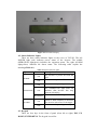
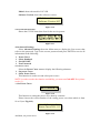
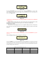
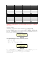
1
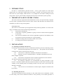
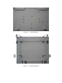
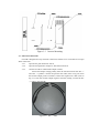
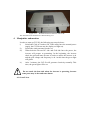
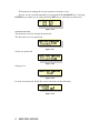
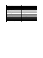
GCI-2K INSTALLATION AND OPERATOR’S MANUAL
Grid-tied inverter for wind
Ningbo Ginlong Technologies
1
2
3
INTRODUCTION
SAFETY GUIDELINES AND WARNINGS
INSTALLATION
3.1 Selecting a location for the inverter
3.2 Mounting the inverter
3.3 Electrical connections
4
MANIPULATE AND MONITOR
4.1 Overall view
4.2 Status Indicator Lights
4.3 Keypad
4.4 Display LCD
4.5 Advanced Info.
4.6 Advanced Settings
5
SPECIFICATIONS
1
INTRODUCTION
GCI-2K is a transformerless grid-tied inverter. It has a good response for wind speed
change and a very wide input voltage range from 30Vdc to 750Vdc. The 40 points power curve
that can be set by the display inside GCI-2k is very helpful for the turbine catching the wind
energy better. Anyway, the GCI-2K is designed for small scale wind turbine system specially.
2
IMPORTANT SAFETY INSTRUCTIONS
The inverter has been engineered and manufactured to ensure your personal safety. Improper
use may result in potential electrical shock or burns. Please read and follow all instructions for
installation, use and servicing of this product.
INTENDED USE
The inverter is constructed as per the applicable safety-technical guidelines. Use the inverter
ongly in installations that meet the following qualifications:
i)
In permanent installations;
ii)
Connected to a separate, grounded AC group, to which no other electrical equipment
is connected;
iii)
The electrical installation must meet the applicable regulations and standards, must
be carried out correctly and must be in a good condition;
iv)
Installed according to the instructions stated in this manual;
v)
According to the technical specifications
3
INSTALLATION
3.1 Selecting a location for the inverter
In choosing a location for the inverter, consideration should be given to the following criteria:
3.1.1
The heat sink temperatures can exceed 75oC. This product must be installed
so that persons will not contact the top of the unit.
3.1.2
The inverter is suitable for installation both indoors and outdoors.
3.1.3
When the inverter is installed outdoors, it should be shielded from rain and
direct sunlight, if possible.
3.1.4
The inverter is designed to suit for extremes temperature for most climates.
The operating ambient temperature range is from -25 oC to 60 oC.
3.1.5
the following clearances are recommended for proper placement of the
inverter: A minimum 500mm clearance between the bottom of the inverter and the ground;
visibility of the operating LED’s and display located at the top front of the inverter box
should be considered.
3.1.6
if the inverter is to be installed in an enclosed space, adequate ventilation must
be provided.
3.2 Mounting the inverter
The inverter should be mounted vertically to a flat, solid surface such as wallboard, concrete
or wood siding. The inverter should be located in close proximity to the turbine generator to
minimize the input wire length.
The mounting bracket provided makes mounting the inverter quick and simple. Inverter
should be mounted in a vertical position as shown in Fig.3-1.
The package includes a hardware kit with four 5.5×38 stainless steel screws , four stainless steel
washers and four SX8 wall plugs for installation of metal bracket to a masonry wall, two M5×25
stainless steel screws for installation of inverter to bracket .
3.2.1
Locate the wall studs in the desired location and align the mounting bracket over
the studs. Mark the mounting holes. For concrete wall mounting the holes should be min. 8 mm in
diameter and min. 40 mm deep. Ensure that locations A , B,C and D (in Fig.3-2) are aligned over
the wall studs.
3.2.2
MAKE SURE BRACKET IS LEVEL.
Ensure points A , B,C and D (in Fig.3-2) are aligned with wall studs. Use 5.5×38 stainless
steel screws , washers and SX8 wall plugs to A, B,C and D (in Fig.3-2) to the wall.
WARNING: Bracket shall be mounted vertically on wall.
3.2.3
Carefully hang the inverter on the upper part of the bracket so that the hooks
located at the rear of the inverter hang over the bracket. Use M5×25 stainless steel screws and
stainless steel washers to secure points G and H (in Fig.3-2) to the bracket .
Figure 3-1
Wall Mounting
E↘
A→
↙F
←B
C →
↑G
← D
↑H
Figure 3-2 Mounting Bracket
Inverter
Figure 3-3 Inverter Mounting
3.3 Electrical connections
GCI-2K is designed for easy electrical connection, and the cover can be able to not open
when connection.
3.3.1
open the AC grid disconnect switch
3.3.2
open the wind generator output AC disconnected switch.
3.3.3
connect GCI-2K to wind turbine output rectifier.
Ensure that output voltage polarity from the rectifier matches the “DC +”
and “DC –” symbols. Connect the positive DC cable (refer to Fig.3-4) from
the rectifier output positive terminal. Connect the negative DC cable (refer to
Fig. 3-5) from the rectifier output negative terminal. Finally, connect the DC
± cable to the GCI-2K.
Figure 3-4 DC+
cable
Figure 3-5
3.3.2
DC- cable
connect GCI-2K to the AC grid switch.
Each GCI-2K have a AC grid terminal connector that is showed in Fig.3-6.
There are “L” “N” “ ” symbol on the connector ( refer to Fig3-7), the Line
wire of grid must be connected to “L” terminal; the Neutral wire of grid must
be connected to “N” terminal; the Earth of grid must be connected to “ ”
(refer to Fig.3-8).
Figure 3-6 AC terminal connector
Figure 3-7 grid terminal connector.2
Figure 3-8 connect the wires to grid terminal
Where, put to terminal coat to the terminal.
Figure 3-9 put the coat to the terminal
Where, put the connector to the GCI-2K.
Figure 3-10 connect the terminal to GCI-2K
Figure 3-11 the final electrical connector of GCI-2K
The final electrical connections is showed in Fig.3-11
4
Manipulate and monitor
In order to start up GCI-2K, the following step must be done:
i)
Switch the Grid AC breaker ON. If the utility have the normal power
supply, the GCI-2k turn on( the display red light on).
ii)
Switch the wind generator breaker on.
iii)
When both the inverter DC side and Grid side have the power, the
inverter will prepare to generating. In the beginning, the inverter
check the grid and inner inverter in order to ensure the inverter is ok
and the grid voltage and frequency is ok. At this time the green light
will glitter.
iv)
After 3 minutes, the GCI-2k will generate electricity normally. This
time, the green light will be on.
Do not touch the heat sink when the inverter is operating, because
some parts may be hot and cause burns.
4.1 Overall view
Figure 4-1 Front Panel display
4.2 Status Indicator Lights
There are three status indicator lights on the cover of GCI-2K. The left
POWER light (red) indicates power status of the inverter. The middle
OPERATION light(green) indicates the operation status. The right ALARM
light(yellow) indicates the alarm status. The following table explain the
meanings(Table 4-1).
Table 4-1 Status Indicator lights
light
Status
ON
POWER
OFF
ON
OPERATION
OFF
BLINKING
ON
ALARM
OFF
Description
The inverter is power on from the
grid
The inverter is power off.
The inverter is operating correctly.
The OPERATION light turns off
indicates that inverter has stop
generate electricity.
The inverter is Initializing.
Alarm or fault condition is detected.
The inverter stores last 10 messages.
The inverter is operating correctly.
4.3 Keypad
There are four keys in the front of panel (from left to right): ESC, UP,
DOWN, ENTER KEYS. The keypad is used for:
¾
¾
Scroll the displayed parameter(UP and DOWN keys);
Accessing and modifying the adjustable parameters (ESC and ENTER keys).
4.4 Display LCD
The two-line Liquid Crystal Display is located on the front panel of inverter.
The LCD shows:
¾ Inverter operation status and data;
¾ Service messages for operator;
¾ Alarm messages and fault indications.
During startup (5 sec), the LCD shows logo of company and model of
inverter(see Figure 4-2).
Figure 4-2
During regular operation, the display will show the power and GCI-2K status
alternately (see Figure 4-3). The display shows a different screen every 10
seconds. Screens can be scrolled manually by pressing the UP and DOWN keys.
Pressing the ENTER key gives access to Main Menu.
Figure 4-3
4.4.1 Main menu
There are four submenus in the main menu. Flowing:
¾ Information
¾ Settings
¾ Advanced Info.
¾ Advanced Settings
Pressing the ESC
key calls back the
previous menu.
Main Menu
Information
Power
19124W
27-11-2008 09:04
UP/DOWN
Settings
5 sec
UP / DOWN or
auto-scroll
(10 sec)
Ginlong
GCI-2K
start
UP/DOWN
Advanced Info.
Status: Generating
27-11-2008 09:04
UP/DOWN
Advanced Settings
Pressing the
ENTER key
gives access to
the main menu.
Figure 4-4 Startup Overall view
The display has 2 lines; use the keys at the side of the display to scroll through
items or open the corresponding submenus. An arrow on the left side of the
display highlights your current selection as shown in the following figure (Figure
4-5):
Figure 4-5
4.4.2 Information
Select the Information menu to display the information of inverter. These
screens appear in the following order(Table 4-2).
Table 4-2 Information Indicator
Display
Duration
Description
10 sec
V_DC: shows input voltage value.
I_DC: shows input current value.
10 sec
V_Grid: shows grid voltage value.
I_Grid: shows grid current value.
10 sec
Status: shows instant status of GCI-2K.
Power: shows instant output power value.
10 sec
F_Grid: shows instant frequency of grid
value.
10 sec
Lifetime energy output value (since first
clearing energy).
This Month: Total energy output during this
month.
10 sec
Last Month: Total energy output of last
month.
During regular operation, the display will show the power and status of inverter
alternately. The display shows a different screen every 10 seconds. Screens can be
scrolled manually by pressing the UP and DOWN keys. Pressing the ESC key calls
back the Main menu. At the same time, ENTER key can make the display lock
(Figure 4-7) and unlock (Figure 4-6). Two figures is in the following.
Figure 4-6
Figure 4-7
Table 4-3 Status Indicator
Display
Generating
Low wind
Initializing
Description
Generating electircity
Wind is low and no output power
Inverter is initializing and ready
to operate
4.4.3 Settings
Select the Settings menu to display the following submenu:
¾ Set Time
¾ Set Address
¾ Clear Energy
¾ Restore Settings
An arrow on left side of the display highlights your current selection. When chosen item
is selected, press ENTER key to open the submenu. Pressing the ESC key calls back the
Main menu.
4.4.3.1 Set Time
This function allows time and data setting.
Pressing UP/DOWN keys to set time and data. Pressing ENTER key to
move from one digit to the next (from left to right). Pressing the ESC key to save
time and data setting, and calls back the pervious menu.
The screen shows in the following figure:
Figure 4-7
4.4.3.2
Set Address
This function is used to set addresses for communication of the single
inverters connected in the system on RS485 line. You can assign number from 1
to 99.
Pressing UP/DOWN keys to set address. Pressing ENTER key to complete
setting of address. Pressing ESC key to cancel pervious setting and call back
pervious menu.
The screen shows in the following figure:
YES=<ENT> NO=<ESC>
Set Address: 02
Figure 4-8
4.4.3.3
Clear Energy
This function is used to clear energy (total energy, this month energy and last
month energy). When selecting Clear Energy, the screen shows in the following
figure:
Figure 4-9
Pressing ENTER key to make sure it setting. Pressing ESC key to cancel pervious
setting and call back pervious menu.
4.4.3.4 Restore Settings
This function is used to restore settings (see Figure 4-10). You must set Grid
OFF before select it. If not, the screen will show in the following figure:
Figure 4-10
Figure 4-11
Pressing ENTER key to make sure it setting. Pressing ESC key to cancel pervious
setting and call back pervious menu.
4.5 Advanced Info.
Select Advanced Info. from the Main menu to display the first screen, that
refers to the password (see Figure 4-12). Type in the correct password and press
ENTER to access all information in the following:
¾ Alarm Message
¾ Temperature
¾ STD NO. & Curve NO.
¾ Version
¾ Communication Data
Figure 4-12
Screens can be scrolled manually by pressing the UP and DOWN keys. Pressing the ENTER
key gives access to Main Menu. Pressing the ENTER key access to submenu.
NOTE: The default password is “0010”
4.5.1 Alarm Message
The display shows 10 alarm messages recently. Screens can be scrolled manually
by pressing the UP and DOWN keys. Pressing the ESC key calls back the pervious
menu.
Figure 4-13
4.5.2 Temperature
The screen shows the power module temperature of GCI-2K.
Figure 4-14
4.5.3 STD NO. & Curve NO.
STD NO.: shows the reference standard of GCI-2K.
Curve NO.: shows power curve version.
Figure 4-15
4.5.4 Version
Model: shows the model of GCI-2K.
Software Version: shows the software version .
Model:
0A
Software Version :903
Figure 4-16
4.5.5 Communication Data
Shows the GCI-2K inner data. Just for the service person.
Figure 4-17
4.6 Advanced Settings
Select Advanced Settings from the Main menu to display the first screen, that
refers to the password. Type in the correct password and press ENTER to access all
information in the following:
¾ Power Curve
¾ Select Standard
¾ Grid ON/OFF
¾ New Password
4.6.1 Power Curve
Select the Power Curve menu to display the following submenu:
¾ Set power Curve
¾ Select Power Curve
This function is used to set and select power curve.
NOTE: in order to make the function availability, you must set Grid OFF first (please
see 4.6.3) .
A) Set Power Curve
Figure 4-18
This function is setting the power curve data by customer.
Please choose the version number of the setting power curve data which is from
01 to 03(see Fig.4-19).
YES=<ENT> NO=<ESC>
Power Curve NO.: 01
Figure 4-19
And then, set power curve:
Figure 4-20
Pressing UP/DOWN keys to set power curve. Pressing ENTER key to move from
power digit to the next (from left to right). Press the ECS key to save and send power
curve ( see Figure 4-21).
Figure 4-21
NOTE:In order to make the power curve setting availability, GCI-2K must be set GRID-ON
NOW (see 4.6.3).
When customer set the power curve (01—03), the power curve data will save to the
EEPROM. Next starting the GCI-2K, the power curve data can be used directly.
B) Select Power Curve
This function is choosing the power curve number. When you have set the power
curve data, you can choose the power curve number which you what to run by this
function.
Figure 4-22
NOTE: in order to make the function availability, you must set Grid OFF first (please
see 4.6.3)
Select the Power Curve menu to display the following:
YES=<ENT> NO=<ESC>
Curve NO.: 01
Figure 4-23
Press the ENTER key to save and send power curve. Pressing ESC key to cancel pervious setting
and call back pervious menu. In this menu, you can select four power curve number from 01 to 04.
The 01,02,03 power curve is the user edit ; the 04 power curve is the GCI-2K default value and be
not able to change (refer to Table 4-4).
Table 4-4 the 04 number power curve
DC value (V)
Power (W)
DC value (V)
Power (W)
30
0
230
990
40
0
240
1050
50
0
250
1110
60
0
260
1170
70
10
270
1220
80
50
280
1300
90
90
290
1400
100
140
300
1500
110
200
310
1600
120
260
350
1800
130
320
390
2000
140
380
430
2000
150
440
470
2000
160
500
510
2000
170
570
550
2000
180
650
590
2000
190
730
630
2000
200
810
670
2000
210
890
710
2000
220
930
750
2000
NOTE:In order to make the power curve setting availability, GCI-2K must be set GRID-ON
NOW (see 4.6.3).
4.6.2 Select Standard
This function is used to select reference standard of grid (see Figure 4-20).
Pressing UP/DOWN keys to select standard (AS4777, VDE0126, UL1741, G83,
User-Def). Pressing ENTER key to complete selection. Pressing ESC key to cancel
pervious setting and call back pervious menu.
YES=<ENT> NO=<ESC>
Standard: G83
Figure 4-24
Select the User-Def menu to display the following submenu:
¾ OV-V: 240---265V
¾ UN-V: 180---210V
¾ OV-G-F: 50.3---52.0Hz(60.3—62.0Hz)
¾ UN-G-F: 47.0---49.5Hz(57.0—59.5Hz)
Figure 4-25
Press the UP/DOWN keys to scroll through items. Press the ECS key to save and
send standard of grid. Press the ENTER key to set standard of grid.
NOTE: in order to make the function availability, you must set Grid OFF
4.6.3 Grid ON/OFF
This function is making the inverter generate electricity or not.
Screens can be scrolled manually by pressing the UP and DOWN keys. Pressing
ENTER key to make sure it setting. Pressing ESC key to call back pervious menu.
Figure 4-26
4.6.4 New Password
This function is used to change the password.
The first time set a new password.
Figure 4-27
Verify new password.
Figure 4-28
Setting is ok.
Figure 4-29
If verify new password failed, the screen will shows in the following:
Figure 4-30
5
SPECIFICATIONS
The DC input range
30V~750Vdc
The rating max dc input current
9Adc
The grid voltage range
180~260Vac (adjustable)
Operation phase
single
Rating grid output current
8.7Aac
Rating output power
2kW
The transient max power
2.2kW
Grid current THD
Total THd<4%,
The dc injection current
<10mA
Output power factor
>0.99
Grid frequency range
50Hz/60Hz (adjustable)
efficiency
94%
Design lifetime
>20 years
Input/output to shell isolation
5M
operation environment temperature
-25~60oC