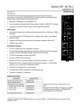
1
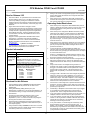
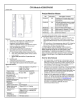
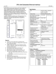
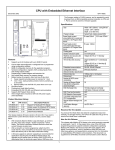
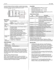
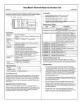
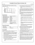
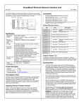
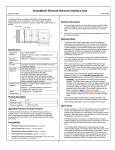
CPU Modules CPU001 and CPU002
June 2010
GFK-1536R
Product Revision History
PWR
OK
Rev
FW version
Description/ / Features
CPU001-HK 2.35
Hardware part change.
CPU001-GK 2.35
Corrections to PID function block, serial
CPU002-EG
communications, and EZ Program Store
device features.
CPU001-FJ 2.34
Support for 32-bit Modbus registers,
CPU002-DF
updated PID function block, higher serial
communications throughput
CPU001-DH 2.31
Support for Modbus® RTU Master
CPU002-BE
CPU001-DG 2.30
Added support for Modbus® RTU Master
CPU002-BD
CPU001-DF 2.20
Added new serial I/O baud rates
CPU002-BC
CPU001-DE 2.10
Hardware-only upgrade to enhance
CPU002-BB
manufacturability.
CPU001-CE 2.10
Support for configurable memory, EZ
CPU002-AB
Program Store Device, High-density
Analog I/O modules, and RTS delay
functionality for RTU and Serial I/O
communications.
CPU001-CD 1.50
Support for CPU002 and expansion I/O.
CPU002-AA
CPU001-BD 1.50
New Release 1.50 firmware loaded onto
CPU001-BC hardware.
Support for expansion I/O.
CPU001-CC 1.20
Hardware-only upgrade to support future
functionality. No customer/user impact
for changes made from –BC version.
CPU001-BC 1.20
Added support for ALG240, 331, 620, and
630 intelligent analog modules.
CPU001-BB 1.10
Added function blocks to scale input data.
Added Drum Sequencer function block.
CPU001-BA 1.00
Updated hardware to support Intelligent
I/O modules
CPU001-AA 1.00
Initial Product Release
RUN
FAULT
FORCE
PORT 1
PORT 2
PORT 1
RS232
PORT 2
RS485
Features
▪
▪
▪
Non-volatile flash memory for program storage
Programming in Ladder Diagram and Instruction List
Battery backup for program, data, and time of day clock
Super capacitor provides power to memory for 1 hour
Over 1 hour, backup battery protects memory contents
up to 6 months.
Backup battery has shelf life of 5 years when not in
use.
Run/Stop switch
Floating point (real) data functions
Embedded RS-232 and RS-485 communications
Supports EZ Program Store device (IC200ACC003)
70mm height when mounted on DIN rail with power supply
▪
▪
▪
▪
▪
▪
▪
▪
Specifications
Size
I/O Discrete Points
Discrete Internal Bits
Discrete Temporary Bits
Global Discrete Bits
Configurable Memory
(Program, Registers, I/O
Analog Words)
Boolean execution speed
Floating Point
Override
Built-in ports
Built-in communications
Type of memory storage
Battery-Backed Real-time
Clock
Realtime clock accuracy (for
timers or timer contacts)
Time-of-day clock accuracy
2.63” (66.8mm) x 5.04” (128mm)
2048 In, 2048 Out
1024 points
256 points
1280 points
CPU001: 34K bytes maximum
CPU002: 42K bytes maximum
Release 2.35 firmware replaces firmware version 2.10 through 2.34. The
following CPUs can be upgraded to the new firmware version:
▪
▪
CPU001 versions CC and later
CPU002: all versions
The following CPUs cannot be upgraded. To use the new features of this
release, new CPU hardware must be purchased:
▪
1.8ms/K (typical)
Yes
Yes
RS-232, RS-485
SNP Slave, RTU Slave, Serial I/O
System flash, battery-backed RAM
Yes
CPU001 versions AA, AB, BA, BB, BC, BD
If you need to determine the current firmware version of a CPU, see the
steps below:
▪
With Machine Edition Logic Developer, go online to the CPU,
then select Target > Online Commands > Show Status. The
Device Information Software Revision shows the current firmware
revision level.
With a VersaPro or Control programmer, attach the CPU. Under
the PLC menu (VersaPro) or the Comm menu (Control), select
the Memory tab on the Status Information dialog.
A firmware upgrade is optional. Upgrading is recommended for
applications that use PID function blocks or serial communications. An
upgrade can be downloaded from www.ge-ip.com.
(For CPU001: 44A747796-G09. For CPU002: 44A751403-G06). The
firmware resides in FLASH memory, and is upgraded by serial download
from a Windows PC via CPU port 1. Port 2 cannot be used for a
firmware upgrade.
▪
100ppm (0.01%) or +/- 9sec/day
23ppm (.0023%)or +/- 2sec/day @
30C;
100 ppm ((0.01%) or +/- 9sec/day @
full temperature range.
1
CPU Modules CPU001 and CPU002
September 2006
GFK-1536R
New for Release 2.35
1.
2.
3.
PID Function Block: An optional filter for the Derivative Term
has been added in version 2.34. This filter improves PID
control loop stability by limiting the contributions of random
variations and step input changes in the Set Point and Process
Variable inputs. For more information, see the last page of this
datasheet.
Support for 32-bit register data to the Modbus RTU master
serial protocol. This feature was previously available in
IC200CPUE05 version 2.32. See the document GFK-2220,
Modbus RTU Master Communications, which is available at
www.ge-ip.com,
for information on using Modbus RTU Master
communications. This document is a supplement to GFK0582, the Serial Communications User's Manual.
Product Information
CPU001-HK, CPU002-EG
Firmware:
Version 2.35
Compatibility,
for configuring
or using new
features:
Machine Edition Logic Developer version 2.11 or
later.
VersaPro software version 1.0 or later for
configuration, 1.5 or later to use new features.
Control software version 2.20 or later.
All types of I/O and communications modules
can be used in expansion racks. Some analog
modules require specific module revisions in
expansion racks, as listed below:
Module
Module Revision
*ALG320
B or later
*ALG321
B or later
*ALG322
B or later
*ALG430
C or later
*ALG431
C or later
*ALG432
B or later
Expansion I/O
Compatibility:
Using repeated port setup COMMREQs to alternate between
SNP slave and Serial I/O protocols will not cause a CPU
Software fault.
2.
Setting both ERROR_TERM_SELECT (bit 3) and
DERIVATIVE_ACTION (bit 0) in the Config Word (Address +12
of the Reference Array) no longer reverses the sign of the PID
derivative term.
3.
Changing the Integral Rate (Ki) parameter value of a PID
function block from 2 to 1 (that is, from 0.002 to 0.001
Repeats/Sec.) or from 1 to 2 does not cause a step change to
the Integral Term and the Control Variable.
4.
5.
7.
When a serial port is configured for either SNP or SNP-X and a
character with a framing error is received on either serial port, the
port continues responding to received characters.
1.
When a serial port is configured for either Modbus RTU (slave or
master) or Serial I/O, and a parity, framing or over-run error occurs
while a serial message is being received, the next message
received is ignored.
2.
When a serial port is configured for Modbus RTU slave, an SNP
master device (for example, a serial programmer or HMI/SCADA
device that uses the SNP protocol) may attach to the port. If the
SNP device is disconnected and then an RTU query is sent to the
port before 10 seconds have elapsed, the port is unable to receive
any serial messages. To recover, power to the CPU must be
turned off and then on.
3.
When a serial port is configured for Serial I/O, and a new hardware
configuration is stored that changes the port protocol to SNP, the
port may not respond to SNP Attach messages until the CPU is
powered off and then on.
4.
In series 90-30 CPUs, the Shift Register Bit (SHIFR_BIT)
instruction may be used to rotate a bit sequence around a range of
discrete references by specifying the same reference for the output,
Q, and the start reference, ST.
However, in VersaMax CPUs, separate references must be used
for ST and Q, and additional logic must be used to copy the output
bit from the Q reference to the ST reference.
Resolved for this Release
1.
Storing a new version of the application program and configuration
using an EZ Program Store device will no longer fail when OEM
protection is enabled.
Operating Notes/Restrictions
Higher Serial Communications Throughput: Serial
communications throughput can be improved in version 2.34 by
configuring the CPU for Constant Sweep Mode and specifying
a sweep time that is significantly longer than the application’s
Normal Mode sweep time. Ethernet, backplane and serial
communications now share the available time at the end of
constant sweeps.
Revision:
6.
5.
When the configured size of a reference table is changed after the
table is stored to flash memory, and the user attempts to read
Initial/Forced Values from flash memory, the table will be filled with
zeros.
6.
Using an older revision non-intelligent analog module in an
expansion rack causes a System Configuration Mismatch error to
be logged. The faulted module must be replaced with a newer
revision before it will be scanned. The allowed revisions are
detailed under Compatibility, in the Product Information section,
above.
7.
Changing an IND or ISA PID function block integral rate parameter
value from 1 (that is, from 0.001 repeats/sec.) to 0 or from 0 to 1
causes a step change in both the integral term and the control
variable (CV) output. This result is expected. A zero integral rate
value specifies that the integral term contribution to CV is zero,
while a non-zero value specifies a non-zero contribution.
8.
If the receiver in a local single rack is powered off while the CPU is
powered on, erroneous ‘Addition of rack’ faults may be logged by
the CPU. It is recommended that both the CPU and the receiver be
powered by a single source.
9.
Occasionally, a "Backplane Communication Fault" may be logged
on an intelligent I/O module after power-cycling the main or
expansion rack. This is a diagnostic fault that can be cleared.
10. In very rare instances, when field power is lost on one module, nonintelligent modules in the same rack may also report faults.
11. In very rare instances, the CPU may not add a module being hot
inserted. It will not generate an ‘Addition of Module’ fault, and the
module will not be scanned. The situation can be corrected by
extracting and re-inserting the module.
When Serial I/O and Hardware Flow Control are specified for
Port 2 in the hardware configuration, transmissions from port 2
will complete properly.
12. In very rare instances, a module being hot inserted may cause
analog modules in the same rack to set outputs to zero. In
addition, ‘Loss of Module’, ‘System Configuration Mismatch’, or
field faults may be generated on other modules in the same rack. If
the modules do not return to correct behavior momentarily, power
cycling will restore full operation.
Using a Serial Port Setup COMMREQ to switch from one serial
communications protocol to another will not cause a Corrupted
User Memory Fault in the PLC Fault Table
2
CPU Modules CPU001 and CPU002
September 2006
GFK-1536R
Module Installation
Removing the CPU from the DIN Rail
This equipment may be mounted on a horizontal or vertical DIN rail.
If mounted on a vertical DIN rail, the CPU module must be located at
the bottom. The CPU and connecting carriers must be installed on
the same section of 35mm x 7.5mm DIN rail, 1mm thick. Steel DIN
rail is recommended. The DIN rail must be electrically grounded to
provide EMC protection. The rail must have a conductive (unpainted)
corrosion-resistant finish. DIN rails compliant with DIN EN50022 are
preferred. For vibration resistance, the DIN rail should be installed
on a panel using screws spaced approximately 15.24cm (6 inches)
apart.
1.
2.
3.
4.
Activating or Replacing the Backup Battery
Rated thermal specifications for the CPU module are based on a
clearance of 2” above and below the equipment and 1” to the left of
the CPU module.
1.
Allow sufficient finger clearance for opening CPU door.
2.
Allow adequate clearance for serial port and Ethernet cables.
3.
Allow adequate space for power wiring.
Turn off power to the power supply.
(If the CPU is attached to the panel with a screw) remove the power
supply module. Remove the panel-mount screw.
Slide the CPU away from the other modules until the connector on
the right side disengages from the next carrier.
With a small flathead screwdriver, pull the DIN rail latch outward
while tilting the other end of the module down to disengage it from
the DIN rail.
The CPU is shipped with a battery already installed. The battery holder
is located in the top side of the CPU module. Before the first use,
activate the battery by pulling and removing the insulator tab.
The CPU with power supply attached fits into a 70mm deep
enclosure.
To replace the battery, use a small screwdriver to gently pry open the
battery holder. Replace battery only with*ACC001 from your PLC
supplier, or with Panasonic battery: BR2032. Use of another battery may
present a risk of fire or explosion.
Installing the CPU on the DIN Rail
The CPU snaps easily onto the DIN rail. No tools are required for
mounting or grounding to the DIN rail.
Caution
Battery may explode if mistreated.
Do not recharge, disassemble, heat above 100 deg.C (212 deg.F) or
incinerate.
Before joining module carriers to the CPU, remove the connector
cover on the right-hand side of the CPU. Do not discard this cover,
you will need to install it on the last carrier, to protect the connector
pins from contamination and damage during use.
Switching the PLC Operating Mode
Panel-Mounting
RUN/ON
If excessive vibration is a factor the CPU should also be screwed
down to the mounting panel.
STOP/OFF
Note 1. Tolerances are +/- 0.13mm (0.005in) non-cumulative.
Note 2. 1.1-1.4Nm (10-12 in/lbs) of torque should be applied to M3.5
(#6-32) steel screw threaded into material containing internal
threads and having a minimum thickness of 2.4mm
(0.093in).
SEE NOTE 2.
4.3mm
0.170in
M3.5 (#6) SCREW
If Run/Stop mode switch operation is enabled, the switch can be used to
place the CPU in Run mode.
SPLIT LOCK
W ASHER
If the CPU has non-fatal faults and is not in Stop/Fault mode, placing the
switch in Run position causes the CPU to go to Run mode. Faults are
NOT cleared.
FLAT WASHER
4.3mm
0.170in
5.1mm
0.200in
15.9mm
0.62in REF
TAPPED
HOLE IN
PANEL
The CPU Run/Stop mode
switch is located behind the
module door. This switch can
be used to place the CPU in
Stop or Run mode. By default.
Run/Stop mode operation is
enabled. The same switch can
also be configured to prevent
writing to program or
configuration memory and
forcing or overriding discrete
data. It defaults to disabled
memory protection.
If the CPU has fatal faults and is in Stop/Fault mode, placing the switch
in Run position causes the Run LED to blink for 5 seconds. While the
Run LED is blinking, the CPU switch can be used to clear the fault table
and put the CPU in Run mode. After the switch has been in Run position
for at least ½ second, move it to Stop position for at least ½ second.
Then move it back to Run position. The faults are cleared and the CPU
goes to Run mode. The LED stops blinking and stays on. This can be
repeated if necessary.
CPU
If the switch is not toggled, after 5 seconds the Run LED goes off and
the CPU remains in Stop/Fault mode. Faults stay in the fault table.
3
CPU Modules CPU001 and CPU002
September 2006
GFK-1536R
Pin Assignments for Port 1
Observing the Module LEDs
PWR
Pin
The LEDs indicate the presence of power and show the
operating mode and status of the CPU.
Signal
Direction
1
n/c
RUN
2
TXD
Output
FAULT
3
RXD
Input
FORCE
4
n/c
PORT 1
5
GND
6
n/c
7
CTS
Input
8
RTS
Output
9
n/c
Shell
SHLD
OK
PORT 2
ON when the CPU is receiving 5V power from the power supply.
Does not indicate the status of the 3.3V power output.
POWER
ON indicates the CPU has passed its powerup diagnostics and is
functioning properly. OFF indicates a CPU problem. Fast blinking
indicates the CPU is running its powerup diagnostics. Slow blinking
indicates the CPU is configuring I/O modules. Simultaneous blinking
of this LED and the green Run LED indicates the CPU is in boot
mode and is waiting for a firmware download through port 1.
OK
Green when the CPU is in Run mode. Amber indicates the CPU is
in Stop/IO Scan mode. If this LED is OFF but OK is ON, the CPU is
in Stop/No IO Scan mode.
RUN
6
ON if the CPU is in Stop/Faulted mode because a fatal fault has
occurred. To turn off the Fault LED, clear both the I/O Fault Table
and the PLC Fault Table. If this LED is blinking and the OK LED is
OFF, a fatal fault has occurred during self-diagnostics. Please
contact PLC Product Support.
FORCE
ON if an override is active on a bit reference.
PORT 1 & 2
Blinking indicates activity on that port.
7
8
9
RS232
PORT 2
1
--
0V/GND signal reference
-Clear to Send input
Request to Send output
--
--
Cable Shield wire connection / 100%
(Continuous) shielding cable shield
connection
1
1
2
2
3
3
4
4
5
5
Cable:
Belden
9610
Either port can be software-configured to set up communications
between the CPU and various serial devices. An external device can
obtain power from Port 2 if it requires 100mA or less at 5VDC.
5
Receive Data input
--
6
7
8
9
PC 9-Pin
Serial Port
9-pin female
(2) RXD
(3) TXD
(5) GND
(7) RTS
(8) CTS
CPU
Port 1
9-pin male
(2) TXD
(3) RXD
(5) GND
(7) CTS
(8) RTS
The shield must attach to shell of
connectors on both ends of the cable.
Vendor Part numbers below are provided for reference only. Any part
that meets the same specification can be used.
The CPU’s two serial ports are software-configurable for SNP slave,
RTU slave, or Serial I/O operation. If a port is being used for RTU, it
automatically switches to SNP slave mode if necessary. Both ports’
default configuration is SNP slave mode. If configured for Serial I/O,
a port automatically reverts to SNP slave when the CPU is in Stop
mode.
1
Transmit Data output
Connector and Cable Specifications for Port 1
Using the CPU Serial Ports
PORT 1
--
Cable Diagram for Attachment to a PC
If RUN is flashing green and the Fault LED is ON, the Run/Stop
switch was moved to Run position while a fatal fault existed.
FAULT
Function
9 Pin Male
Connector:
Port 1 is an RS-232 port with a 9-pin female D-sub connector. It
is used as the boot loader port for upgrading the CPU firmware.
The pinout of port 1 allows a simple, straight-through cable to
connect with a standard AT-style RS-232 port. Cable shielding
attaches to the shell. Port 1 screw locks are threaded #4-40.
Computer cable, overall braid over foil shield
5 conductor †
30 Volt / 80°C (176°F)
24 AWG tinned copper, 7x32 stranding
Vendor:
Plug:
Pin:
Type:
ITT/Cannon
Crimp
DEA9PK87F0
030-2487-017
AMP
205204-1
66506-9
Solder
Connector
Shell:
Port 2 is an RS-485 port with a 15-pin female D-sub connector.
This can be attached directly to an RS-485 to RS-232 adapter
(IC690ACC901). Port 2 can be use for program, configuration,
and table updates with the EZ Program Store module. Port 2
screw locks are threaded (metric) M3x0.5).
†
*
8
RS485
4
ITT/Cannon
AMP
ZDE9P
747904-2
---
Kit* – ITT Cannon DE121073-54 [9-pin size backshell kit]:
Metal-Plated Plastic (Plastic with Nickel over Copper) †
Cable Grounding Clamp (included)
40° cable exit design to maintain low-profile installation
Plus – ITT Cannon 250-8501-010 [Extended Jackscrew]:
Threaded with #4-40 for secure attachment to port †
Order Qty 2 for each cable shell ordered
Critical Information – any other part selected should meet or exceed this criteria.
Use of this kit maintains the 70mm installed depth.
CPU Modules CPU001 and CPU002
September 2006
GFK-1536R
Pin Assignments for Port 2
Pin
Signal
Direction
Function
1
SHLD
--
Cable Shield Drain wire connection
2, 3, 4
n/c
5
P5V
Output
+5.1VDC to power external level converters
(100mA max.)
6
RTSA
Output
Request to Send (A) output
7
GND
--
0V/GND reference signal
8
CTSB’
Input
Clear to Send (B) input
9
RT
--
Resistor Termination (120 ohm) for RDA’
10
RDA’
Input
Receive Data (A) input
Connector and Cable Specifications for Port 2
Vendor Part numbers below are provided for reference only. Any part
that meets the same specification can be used.
--
11
RDB’
Input
Receive Data (B) input
12
SDA
Output
Transmit Data (A) output
13
SDB
Output
Transmit Data (B) output
14
RTSB
Output
Request to Send (B) output
15
CTSA’
Input
Clear to Send (A) input
Shell
SHLD
--
Cable Shield wire connection / 100%
(Continuous) shielding cable shield
connection
Cable:
Belden
8105
15 Pin Male
Connector:
Connector
Shell:
†
*
Low Capacitance Computer cable, overall braid over foil
shield
5 Twisted-pairs †
Shield Drain Wire †
30 Volt / 80°C (176°F)
24 AWG tinned copper, 7x32 stranding
Velocity of Propagation = 78%
Nominal Impedance = 100Ω †
Vendor:
Plug:
Pin:
Type:
Crimp
ITT/Cannon
DAA15PK87F0
030-2487-017
AMP
205206-1
66506-9
Solder
ITT/Cannon
ZDA15P
-AMP
747908-2
-Kit*– ITT Cannon DA121073-50 [15-pin size backshell kit]:
Metal-Plated Plastic (Plastic with Nickel over Copper) †
Cable Grounding Clamp (included)
40° cable exit design to maintain low-profile installation
Plus – ITT Cannon 250-8501-009 [Extended Jackscrew]:
Threaded with (metric) M3x0.5 for secure attachment †
Order Qty 2 for each cable shell ordered
Critical Information – any other part selected should meet or exceed this criteria.
Use of this kit maintains the 70mm installed depth.
Cable Lengths
Maximum cable lengths the total number of feet from the CPU to the last
device attached to the cable are:
Port 1 (RS-232) = 15 meters (50 ft.)
Port 2 (RS-485) = 1200 meters (4000 ft.)
Serial Port Baud Rates
RTU protocol
Serial I/O protocol
SNP protocol
Port 1
1200, 2400, 4800, 9600,
19.2K
1200, 2400, 4800, 9600,
19.2K
4800, 9600, 19.2K, 38.4K*
* Only available on one port at a time.
5
Port 2
1200, 2400, 4800, 9600,
19.2K
1200, 2400, 4800, 9600,
19.2K
4800, 9600, 19.2K, 38.4K*
CPU Modules CPU001 and CPU002
September 2006
GFK-1536R
(table continued)…
PID Function Parameter Block
Bit 3:
Deadband
action
In chapter 14 of the VersaMax PLC User’s Manual, GFK-1503C, the
table showing the Parameter Block for the PID function should be
modified as described below.
For Address +12 (Config Word), the three rightmost columns are
now:
Low
Bit
Units
Range
If bit 3 is 1, deadband action occurs. If the
error term is within the deadband limits,
then the error is forced to zero. If,
however, the error term is outside the
deadband limits, then the error term is
reduced by the deadband limit: Error Term
= Error Term - deadband limit.
A similar adjustment occurs when the error
term is less than the lower deadband limit.
Description
The low 6 bits of this word are used to
modify six default PID settings. The 10 highorder bits should be set to 0.
Low 6
bits
used
Set the low bit (bit 0) to 1 to modify the
standard PID Error Term from the normal
(SP – PV) to (PV – SP), reversing the sign of
the feedback term. This is for Reverse
Acting controls where the CV must go down
when the PV goes up.
Bit 4: Antiresetwindup
action
Set the second bit (bit 1) to 1 to invert the
Output Polarity so that CV is the negative of
the PID output rather than the normal
positive value.
Set the fourth bit (bit 3) to activate deadband
processing.
Set the fifth bit (bit 4) to activate anti-resetwindup action.
Bit 5:
Derivative
Term filter
When bit 5 is 0, no derivative term filtering
occurs.
Bit 0 - Bit 5:
Remember that the bits are set in powers
of 2.
Set the sixth bit (bit 5) to activate derivative
filtering.
The low 6 bits in the Config Word are
defined in detail below:
When bit 0 is 0,
Error Term = SP - PV.
When bit 1 is 0, the CV output represents
the output of the PID calculation. When bit 1
is set to 1, the CV output represents the
negative of output of the PID calculation.
Bit 2:
Derivative
action on
PV
When bit 2 is 0, the derivative action is
applied to the error term. When bit 2 is 1, the
derivative action is applied to PV.
When bit 5 is 1, the rate of change of the
Derivative Term is limited. This improves
PID loop stability by reducing the effects of
random variations (noise) and step
changes in the Set Point and Process
Variable inputs.
To set bit 0, add 1 to the Config Word
parameter value.
When bit 0 is 1,
eError tTerm = PV - SP.
Bit 1:
Output
Polarity
When bit 4 is 0, the anti-reset- windup
action uses a reset back-calculation. When
the output is clamped, this replaces the
accumulated Y remainder value with
whatever value is necessary to produce the
clamped output exactly.
When bit 4 is 1, the accumulated Y term is
replaced by the value of the Y term at the
start of the calculation. In this way, the preclamp Y value is held as long as the output
is clamped.
Set the third bit (bit 2) to 1 to modify the
Derivative Action from using the normal
change in the Error term to the change in the
PV feedback term.
Bit 0: Error
Term +/-
When bit 3 is 0, no deadband action
occurs. If the error is within the deadband
limits, then the error term is set to zero.
Otherwise the error term is not affected by
the deadband limits.
To set bit 1, add 2.
To set bit 2, add 4.
To set bit 3, add 8.
To set bit 4, add 16.
To set bit 5, add 32.
For example, set Config Word to 0 for
default PID configuration. Add 1 to change
the Error Term from SP - PV to PV - SP,
add 2 to change the Output Polarity from
CV = PID Output to CV = – PID Output, or
add 4 to change Derivative Action from
Error rate of change to PV rate of change,
etc.
6