1
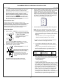
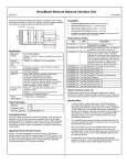
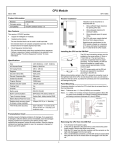
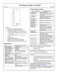
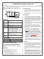
VersaMax® Ethernet Network Interface Unit
December 2006
GFK-1859E
The Ethernet Network Interface Unit (ENIU) is an Ethernet slave
module that acts as controller for a set of I/O modules. Power for
module operation is provided by a power supply that installs directly on
the NIU
Ethernet NIU
Fixed for this Version
▪
If the application opens and closes telnet sessions rapidly (100us
range), the Ethernet cable can be disconnected without causing
loss of the Ethernet NIU or flashing error code 25 on the Fault
LED.
▪
Discrete I/O module faults can now be cleared regardless of where
the module is located.
power supply
Operating Notes
▪
The Ethernet NIU assigns references in the EGD datagrams
according to the physical order of I/O modules in the backplane.
The downloaded hardware configuration is not used to assign I/O
to EGD datagrams. (If a hardware configuration containing I/O
addresses in a different order than the physical module locations is
downloaded to the ENIU, the references are assigned to EGD
datagrams based on the physical module location and not the
downloaded configuration.)
▪
The VersaMax power supply connected to the Ethernet NIU and
any power supplies that reside in a booster carrier must share the
same external power source.
▪
After a point fault occurs on an IC200MDL730A discrete input
module, two clear fault table commands must be sent to the
VersaMax ENIU to clear the fault table and turn the Fault LED off.
This issue does not occur when using IC200MDL730B and later
I/O module hardware.
▪
Documentation note: The warning regarding hold last state
operation on Page 1-7 of the VersaMax System Ethernet
Network Interface Unit User’s Manual (GFK-1860A) should read:
Specifications
Ethernet IP
address
Ethernet
network data
rate
I/O data
Fault data
LEDs (5)
Number of I/O
modules
Power
Consumption
Any Valid IP Address
Default is 195.0.0.x, where x is selected on the
rotary switches.
10Base-T or 100Base-TX, auto-negotiated
1024 bytes maximum. Up to 512 bytes of inputs or
512 bytes of outputs.
128 bytes maximum
Power LED indicates presence of input power
OK LED indicates health of the ENIU
Faults LED indicates presence of faults
LAN LED indicates health of Ethernet network
Stat LED solid green indicates Modbus connection
present or receipt of EGD exchanges; flashing
Amber indicates invalid IP address
Release 1.0 supports 8 I/O modules and no
expansion racks
Release 1.1 and later releases support 64 I/O
modules and 7 expansion racks.
WARNING: “For both discrete and analog Output or Mixed
modules, if the ENIU loses power but the Output or Mixed
modules do not lose power, the Hold Last State parameter does
not work as might be expected. Upon ENIU power loss, outputs
configured for Hold Last State go to the Last State value on
modules that still have power. When power is restored to the
ENIU, outputs go to zerothe Default value. When
communications are reestablished and the ENIU receives a
Write message, outputs go to the values in the ENIU’s Output
Table.”
+5V@175mA, +3.3V@425mA
Product Description
Revision:
DF
Firmware version:
1.31
Firmware upgrades:
44A751424-G05
This warning applies to both Modbus and EGD operation. The
current user’s manual revision indicates it applies only to Modbus.
These changes will appear in the next revision of the manual.
Open Issues
Upgrading Previous Firmware Versions
▪
The Ethernet Network Interface Unit (ENIU) firmware resides in
FLASH memory. This firmware may be upgraded via a download
from an appropriate personal computer connected to the Ethernet
connector (RJ-45) on the ENIU. The download uses an FTP session
to the ENIU.
On rare occasions, a verify or clear operation from the programmer
will fail. The programmer may display the message "Online
operation not supported on current target. Cannot continue current
operation." Retry the verify or clear operation to resolve this issue.
Occasionally, two retries are needed.
▪
If the Ethernet NIU is connected to an Ethernet hub, excessive
multiple collisions may cause Ethernet communication to stop and
restart. Replacing the Ethernet hub with a switch resolves the
issue.
▪
If the IC200ALG240 Analog Input module generates a large
number (approximately 10 or more) faults at the same time, not all
of the faults are reported in the Ethernet NIU’s fault table. There is
no notification that some of the faults are lost. This only occurs
when the faults are generated in close proximity to each other. For
example, an ALG240 configured for 4-20mA current mode will
generate three faults per point if all of the inputs are left open.
Compatibility
▪
▪
▪
▪
▪
Protocols, Modbus Ethernet, Class 0 & 1: all releases
Ethernet Global Data: Release 1.1 and later releases
High density analog modules: Release 1.1 and later
Hot Insertion for I/O modules: Release 1.1 and later
Intelligent I/O module indirect firmware upgrades using the serial TAN
connector: firmware version 1.30 and later.
1
VersaMax® Ethernet Network Interface Unit
December 2006
GFK-1859E
(Open Wire, Low Alarm, and Out of Range) Only seven to ten
of the faults generated are reported in the ENIU fault table.
▪
3.
The Ethernet NIU does not re-report unresolved Loss of Module
faults after its fault table is cleared. (If the loss of module
condition still exists after the ENIU’s fault table is cleared, the
fault is not re-reported.) For example: When an I/O module is
hot-extracted from the backplane, a Loss of I/O Module fault is
recorded in the ENIU’s fault table. If the fault table is cleared,
the Loss of I/O Module fault is not re-recorded even though the
I/O module is still missing from the backplane.
Set the IP Address - Adjust the rotary switches on the front of
the NIU using a 2.44mm (3/32in) flat screwdriver. These switches,
marked IP Address A.B.C.x / X100, X10 and X1, select the
hundreds, tens, and ones digits of the last field in the Ethernet IP
address. The first three fields in the IP address, A.B.C., are fixed
to 195.0.0. when the unit is shipped from the factory. For the last
field, select any valid address in the range 1-254. Always cycle
power to the NIU after changing the switch settings.
IP ADDRESS A.B.C.x
Preinstallation Check
Carefully inspect all shipping containers for damage. If any
equipment is damaged, notify the delivery service immediately. Save
the damaged shipping container for inspection by the delivery
service. After unpacking the equipment, record all serial numbers.
Save the shipping containers and packing material in case it is
necessary to transport or ship any part of the system.
4.
Quick Start Guide
1.
9 0 1
2
3
X100
8
7
2
3
X10
8
7
2
3
X1
8
7
6 5 4
9 0 1
6 5 4
9 0 1
6 5 4
Alternate Method to set Temporary IP Address using Telnet
NOTE: This step is an alternate to Step 3 above. The address
set with this method is temporary. It is lost if power is cycled.
Install the NIU on the DIN Rail by simply clicking it into place.
a.
Note: The NIU and connecting carriers
must be installed on the same section
of 35mm x 7.5mm DIN rail.
The DIN rail must have a conductive
(unpainted) finish for proper
grounding.
The ENIU and the personal computer must be operational and
interconnected via an Ethernet connection. At the computer’s
DOS command prompt, type in the following, then press the
Enter key:
arp –s (IP address you want to assign to ENIU) (MAC
address of the ENIU) (IP address of your computer)
For example: arp –s 3.16.27.5 08-00-19-01-48-64 3.16.88.139
NOTE: You will not see any reply on the screen.
(Refer to the heading Module Installation for information
about space requirements or module orientation, or if you are
installing the NIU in an area of excessive vibration).
2.
b.
Install the Power Supply on the NIU.
To verify that the ARP table entry was accepted, type the
following at the command prompt, then press the Enter key:
arp –a
The latch on the power supply must be
in the unlocked position.
An entry matching the desired ENIU IP address (“Internet
Address”) and MAC address (“Physical Address”) should be
seen in the ARP table, with the “Type” listed as 'static.'
Align the connectors and the latch post
and press the power supply module
down until the two tabs on the bottom of
the power supply click into place.
ARP Table Entry Example
Turn the latch to the locked position to
secure the power supply to the top of
the NIU.
Internet
Address
Physical Address
Type
3.16.27.5
08-00-19-01-48-64
static
c.
Complete the power supply wiring as described in the
installation instructions provided with the Power Supply.
Next, create a Telnet connection to the ENIU (Port 1) by typing
in the following command at the computer’s MS-DOS prompt,
then pressing the Enter key:
telnet (IP Address) 1
For example: telnet 3.16.27.5 1
A Telnet window will appear. After several seconds, a “Connect
Failed!” dialog box will appear; regardless, the ENIU will change
its IP address to the one designated in the Telnet command.
(NOTE: If it takes more than 15 seconds for the Connect Failed
box to appear, the Telnet command probably didn’t work.)
NOTE: Step 4 sets a temporary IP address that will be lost if
power is cycled. To set a permanent (non-volatile) address,
use the programmer software and “store” a configuration
containing the correct IP address. NOTE: A device will need to
be configured in the communications setup for the temporary IP
address to allow you to perform the configuration store.
2
VersaMax® Ethernet Network Interface Unit
December 2006
5.
Connect the communications bus to the connector on the
front of the ENIU. (Refer to the heading Bus Installation
Guidelines for detailed bus installation instructions.)
6.
Remove the connector cover on the right-hand side of
the ENIU. Do not discard this cover; you will need to install it
on the last carrier. It protects the connector pins from
damage and ESD during handling and use. Do not remove
the connector cover on the left-hand side.
7.
8.
GFK-1859E
10. Observe the Module LEDs. The LEDs indicate the presence of
power and show the operating mode and status of the NIU.
OK
FAULTS
LAN
STAT
Install additional modules. Mount a module on its carrier
and slide it to the left along the DIN-rail to fully engage the
connector on the adjacent carrier or ENIU. Repeat for other
modules, and install the connector cover (see Step 6) on the
last carrier.
Green indicates power is applied to
the ENIU.
OK
Green indicates the ENIU firmware
is operational.
FAULTS
Amber indicates the ENIU has
detected a fault with itself or an I/O
module. Blinking amber indicates a
Fatal Fault with the ENIU
LAN
Green (solid or blinking) indicates
network packets are being received
or transmitted. Indicates received
data addressed to ENIU as well as
broadcast data.
STAT
Modbus Mode. Solid Green
indicates a Modbus connection.
Amber blinking at 1/sec rate
indicates an IP address problem.
EGD Mode. Solid Green indicates
exchanges are being received.
Amber blinking at 1/sec rate
indicates an IP address problem.
Configuration. A configuration can be stored by programming
software, or the ENIU can be autoconfigured. When power is
applied to the ENIU for the very first time, the ENIU will
autoconfigure the modules physically present in the I/O station,
starting at Slot 1. Autoconfiguration stops at the first empty slot
or faulted module. If the autoconfiguration is unsuccessful or a
new autoconfiguration is required, it is necessary to first clear
the existing configuration from the ENIU. This is done by
powering down the ENIU, disconnecting the ENIU from the first
I/O carrier, and powering up the ENIU.
vGeneral
Module Installation Instructions
Modules must be mounted on a
horizontal DIN rail.
1
133.35mm
(5.25in)
Note: If the I/O station includes any additional power supplies,
those power supplies must be turned on either before the ENIU
Power Supply or at the same time to assure accurate
autoconfiguration.
9.
PWR
PWR
Allow sufficient finger clearance
for opening NIU door.
2.
Allow adequate clearance for
serial port cables.
3.
Allow adequate space for power
wiring.
The NIU with power supply attached fits
into a 70mm deep enclosure.
2
85.85mm
(3.38in)
Power up the NIU. The modules in the I/O station will
automatically be configured, starting at slot 1 in each rack
including expansion racks. If an empty slot or faulted module is
encountered, autoconfiguration for that rack stops.
Autoconfiguration then skips to the next rack and continues
until all racks are configured.
1.
Rated thermal specifications are based
on a clearance of 5.1cm (2in) above
and below the equipment and 2.54cm
(1in) to the left of the NIU module.
3
Panel-Mounting
Note: If the I/O station includes any additional power supplies,
those power supplies should be turned on at the same time.
For best stability, the DIN rail should be installed on a panel using
screws spaced approximately 5.24cm (6in) apart.
If excessive vibration is a factor the NIU should also be screwed down
to the mounting panel.
Note 1. Tolerances are +/- 0.13mm (0.005in) non-cumulative.
Note 2. 1.1-1.4Nm (10-12 in/lbs) of torque should be applied to M3.5 (#632) steel screw threaded into material containing internal threads
and having a minimum thickness of 2.4mm (0.093in).
SEE NOTE 2.
4.3mm
0.170in
M3.5 (#6) SCREW
SPLIT LOCK
WASHER
FLAT WASHER
4.3mm
0.170in
5.1mm
0.200in
3
15.9mm
0.62in REF
TAPPED HOLE
IN PANEL
NIU
VersaMax® Ethernet Network Interface Unit
December 2006
GFK-1859E
Removing the NIU from the DIN Rail
1.
2.
3.
4.
Turn off power to the power supply.
(If the NIU is attached to the panel with a screw) remove the
power supply module. Remove the panel-mount screw.
Slide the NIU away from the other modules until the
connector on the right side disengages from the next carrier.
With a small flathead screwdriver, pull the DIN rail latch out while
tilting the other end of the NIU down to disengage it from the DIN
rail.
Bus Installation Guidelines
The proper cable for an Ethernet 10Base-T/100Base-TX network is
a four twisted-pair, Category 5 Ethernet cable. The following table
summarizes key characteristics of the Ethernet network and cable.
Network Topology
Point-to point Ethernet 10BaseT/100Base-TX connections with no
termination. “Points” can be hubs or
switches. If only 2 nodes are present, a
crossover cable should be used to
connect them.
Point-to point
distance
Maximum of 100 meters.
Medium
Four twisted-pair unshielded cable.
Shielding is permissible, but not required.
Transmission
Speed
10 Mbit/s (10Base-T) or 100 Mbit/s
(100Base-TX)
Connector
RJ-45
Cable Type
Category 5 (“Cat 5”)
Termination
No termination required
Bus Connector
RJ-45 Connector Pin Assignment
Pin
Signal
I/O
Description
1
Tx+
O
+Transmit output
2
Tx-
O
- Transmit output
3
Rx+
I
+ Receive input
4
FGND
-
Frame Ground
5
FGND
-
Frame Ground
6
Rx-
I
- Receive Input
7
FGND
-
Frame Ground
8
FGND
-
Frame Ground
Pin 1
ENIU
Connector
Front View
Ethernet MAC Address
The ENIU’s MAC (physical) address is labeled on the front of the
ENIU module (see the section “ENIU’s Physical Features” earlier in
this document).
4