1
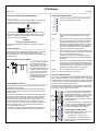
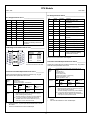
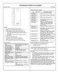
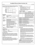
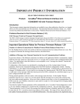
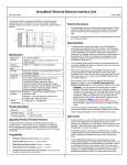
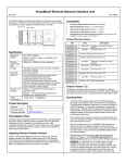
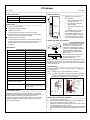
CPU Module March 1999 GFK-1536C Product Information _________________________________ Revision: CPU001-BB Firmware version: 1.10 Compatibility: VersaPro software version 1.0 Module Installation _________________________________ Modules must be mounted on a horizontal DIN rail. 1 2 New Features ____________________________________ 133.35mm (5.25in) This version of CPU001 provides: Support for intelligent I/O modules. Scaling function blocks. 3 Drum Sequencer function block. This new function block works like a mechanical drum sequencer. It allows a sequence of output combinations to be selected in turn. See the heading “The Drum Sequencer Function” for more information. 2. Allow adequate clearance for serial port cables. 3. Allow adequate space for power wiring. Rated thermal specifications for the CPU module is based on a clearance of 2” above and below the equipment and 1” to the left of the CPU module. One function block is for unipolar (unsigned) input data. The other function block is for bipolar (signed) input data. Allow sufficient finger clearance for opening CPU door. The CPU with power supply attached fits into a 70mm deep enclosure. 66.80mm (2.63in) Two new function blocks can be used to scale input data. 1. Installing the CPU on the DIN Rail The CPU and connecting carriers must be installed on the same section of 35mm x 7.5mm DIN rail. The rail must have a conductive (unpainted) finish for proper grounding. For best stability, the DIN rail should be installed on a panel using screws spaced approximately 6 inches (5.24cm) apart. Specifications Size 2.63” (66.8mm) x 5.04” (128mm) I/O Discrete Points 2048 In, 2048 Out I/O Analog Words 128 In, 128 Out Registers 2048 words Discrete Internal Bits 1024 points Discrete Temporary Bits 256 points Global Discrete Bits 1280 points Program Memory 12288 bytes Before joining module carriers to the CPU, remove the connector cover on the righthand side of the CPU. Do not discard this cover, you will need to install it on the last carrier, to protect the connector pins from contamination and damage during use. Boolean execution speed 1.8ms/K (typical) Panel-Mounting __________________________________ Floating Point Yes Override Yes If excessive vibration is a factor the CPU should also be screwed down to the mounting panel. Built-in ports RS-232, RS-485 Built-in communications SNP Slave, RTU Slave, Serial I/O Type of memory storage System flash, battery-backed RAM Battery-Backed Real-time Clock Yes Realtime clock accuracy (used for timers or timer contacts) 100ppm (0.01%) or +/- 9sec/day Time-of-day clock accuracy 23ppm (.0023%)or +/- 2sec/day @ 30C; 100 ppm ((0.01%) or +/- 9sec/day @ full temperature range. The CPU snaps easily onto the DIN rail. No tools are required for mounting or grounding to the DIN rail. Note 1. Tolerances are +/- 0.13mm (0.005in) non-cumulative. Note 2. 1.1-1.4Nm (10-12 in/lbs) of torque should be applied to M3.5 (#632) steel screw threaded into material containing internal threads and having a minimum thickness of 2.4mm (0.093in). SEE NOTE 2. 4.3mm 0.170in M3.5 (#6) SCREW SPLIT LOCK W ASHER FLAT W ASHER 4.3mm 0.170in 5.1mm 0.200in Preinstallation Check _____________________________ Carefully inspect all shipping containers for damage. If any equipment is damaged, notify the delivery service immediately. Save the damaged shipping container for inspection by the delivery service. After unpacking the equipment, record all serial numbers. Save the shipping containers and packing material in case it is necessary to transport or ship any part of the system. 15.9mm 0.62in REF TAPPED HOLE IN PANEL CPU Removing the CPU from the DIN Rail ___________________ 1. 2. 3. 4. 1 Turn off power to the power supply. (If the CPU is attached to the panel with a screw) remove the power supply module. Remove the panel-mount screw. Slide the CPU away from the other modules until the connector on the right side disengages from the next carrier. With a small flathead screwdriver, pull the DIN rail latch outward while tilting the other end of the module down to disengage it from the DIN rail. CPU Module March 1999 GFK-1536C Activating or Replacing the Backup Battery ______________ Observing the Module LEDs _________________________ PWR The CPU is shipped with a battery already installed. The battery holder is located in the top side of the CPU module. Before the first use, activate the battery by pulling and removing the insulator tab. The LEDs indicate the presence of power and show the operating mode and status of the CPU. OK RUN FAULT FORCE PORT 1 PORT 2 To replace the battery, use a small screwdriver to gently pry open the battery holder. Replace battery only with IC200ACC001 from your PLC supplier, or with Panasonic battery: BR2032. Use of another battery may present a risk of fire or explosion. Caution POWER ON when the CPU is receiving 5V power from the power supply. Does not indicate the status of the 3.3V power output. OK ON indicates the CPU has passed its powerup diagnostics and is functioning properly. OFF indicates a CPU problem. Fast blinking indicates the CPU is running its powerup diagnostics. Slow blinking indicates the CPU is configuring I/O modules. Simultaneous blinking of this LED and the green Run LED indicates the CPU is in boot mode and is waiting for a firmware download through port 1. RUN Green when the CPU is in Run mode. Amber indicates the CPU is in Stop/IO Scan mode. If this LED is OFF but OK is ON, the CPU is in Stop/No IO Scan mode. Battery may explode if mistreated. Do not recharge, disassemble, heat above 100 deg.C (212 deg.F) or incinerate. Autoconfiguration __________________________________ At powerup, the CPU by default automatically generates a configuration that includes all of the modules that are physically present in the system, starting at slot 1. Autoconfiguration stops at the first empty slot or faulted module. If RUN is flashing green and the Fault LED is ON, the Run/Stop switch was moved to Run position while a fatal fault existed. Switching the PLC Operating Mode ____________________ RUN/ON STOP/OFF The CPU Run/Stop mode switch is located behind the module door. This switch can be used to place the CPU in Stop or Run mode. By default. Run/Stop mode operation is enabled. The same switch can also be configured to prevent writing to program or configuration memory and forcing or overriding discrete data. It defaults to disabled memory protection. FAULT ON if the CPU is in Stop/Faulted mode because a fatal fault has occurred. To turn off the Fault LED, clear both the I/O Fault Table and the PLC Fault Table. If this LED is blinking and the OK LED is OFF, a fatal fault has occurred during self-diagnostics. Please contact PLC Field Service. FORCE ON if an override is active on a bit reference. PORT 1 & 2 Blinking indicates activity on that port. Using the CPU Serial Ports __________________________ The CPU’s two serial ports are software-configurable for SNP slave, RTU slave, or Serial I/O operation. If a port is being used for RTU, it automatically switches to SNP slave mode if necessary. Both ports’ default configuration is SNP slave mode. If configured for Serial I/O, a port automatically reverts to SNP slave when the CPU is in Stop mode. Run/Stop Mode Operation ____________________________ Either port can be software-configured to set up communications between the CPU and various serial devices. An external device can obtain power from Port 2 if it requires 100mA or less at 5VDC. If Run/Stop mode switch operation is enabled, the switch can be used to place the CPU in Run mode. If the CPU has non-fatal faults and is not in Stop/Fault mode, placing the switch in Run position causes the CPU to go to Run mode. Faults are NOT cleared. PORT 1 If the CPU has fatal faults and is in Stop/Fault mode, placing the switch in Run position causes the Run LED to blink for 5 seconds. While the Run LED is blinking, the CPU switch can be used to clear the fault table and put the CPU in Run mode. After the switch has been in Run position for at least ½ second, move it to Stop position for at least ½ second. Then move it back to Run position. The faults are cleared and the CPU goes to Run mode. The LED stops blinking and stays on. This can be repeated if necessary. 1 5 RS232 PORT 2 If the switch is not toggled, after 5 seconds the Run LED goes off and the CPU remains in Stop/Fault mode. Faults stay in the fault table. 1 Port 1 is an RS-232 port with a 9-pin female D-sub connector. It is used as the boot loader port for upgrading the CPU firmware. The pinout of port 1 allows a simple, straight-through cable to connect with a standard AT-style RS-232 port. Cable shielding attaches to the shell. Port 1 screw locks are threaded #4-40. Port 2 is an RS-485 port with a 15-pin female D-sub connector. This can be attached directly to an RS485 to RS-232 adapter (IC690ACC901). Port 2 screw locks are threaded (metric) M3x0.5). Cable Lengths and Baud Rates Maximum cable lengths (the total number of feet from the CPU to the last device) are: Port 1 (RS-232) = 15 meters (50 ft.) Port 2 (RS-485) = 1200 meters (4000 ft.) 8 RS485 2 Both ports support configurable baud rates from 4800 to 38.4k bps. CPU Module March 1999 GFK-1536C Pin Assignments for Port 2 __________________________ Pin Assignments for Port 1 ___________________________ Pin Signal 1 n/c 2 TXD Direction Function Pin Signal Direction Function 1 SHLD -- Cable Shield Drain wire connection Output +5.1VDC to power external level converters (100mA max.) -Transmit Data output 2, 3, 4 n/c Input Receive Data input 5 P5V -- 0V/GND signal reference 6 RTSA Output Request to Send (A) output 7 GND -- 0V/GND reference signal 8 CTSB’ Input Clear to Send (B) input 9 RT -- Resistor Termination (120 ohm) for RDA’ Receive Data (A) input Output 3 RXD 4 n/c 5 GND 6 n/c 7 CTS Input Clear to Send input 8 RTS Output Request to Send output -- 10 RDA’ Input -- Cable Shield wire connection / 100% (Continuous) shielding cable shield connection 11 RDB’ Input Receive Data (B) input 12 SDA Output Transmit Data (A) output 13 SDB Output Transmit Data (B) output 14 RTSB Output Request to Send (B) output 15 CTSA’ Input Clear to Send (A) input Shell SHLD -- Cable Shield wire connection / 100% (Continuous) shielding cable shield connection --- 9 n/c Shell SHLD Cable Diagram for Attachment to a PC __________________ 1 1 2 2 6 6 7 7 3 3 8 9 8 4 4 5 5 9 PC 9-Pin Serial Port 9-pin female (2) RXD (3) TXD (5) GND (7) RTS (8) CTS CPU Port 1 9-pin male (2) TXD (3) RXD (5) GND (7) CTS (8) RTS See the PLC User’s Manual for cable diagrams. Connector and Cable Specifications for Port 2 ___________ The shield must attach to shell of connectors on both ends of the cable. Vendor Part numbers below are provided for reference only. Any part that meets the same specification can be used. Cable: Belden 8105 Connector and Cable Specifications for Port 1 ___________ Vendor Part numbers below are provided for reference only. Any part that meets the same specification can be used. Cable: Belden 9610 9 Pin Male Connector: Computer cable, overall braid over foil shield 5 conductor † 30 Volt / 80°C (176°F) 24 AWG tinned copper, 7x32 stranding Vendor: Pin: Plug: Type: ITT/Cannon Crimp DEA9PK87F0 030-2487-017 AMP 205204-1 66506-9 Solder Connector Shell: † * -- ITT/Cannon AMP ZDE9P 747904-2 15 Pin Male Connector: Connector Shell: --- Kit* – ITT Cannon DE121073-54 [9-pin size backshell kit]: Metal-Plated Plastic (Plastic with Nickel over Copper) † Cable Grounding Clamp (included) 40° cable exit design to maintain low-profile installation Plus – ITT Cannon 250-8501-010 [Extended Jackscrew]: Threaded with #4-40 for secure attachment to port † Order Qty 2 for each cable shell ordered † * Critical Information – any other part selected should meet or exceed this criteria. Use of this kit maintains the 70mm installed depth. 3 Low Capacitance Computer cable, overall braid over foil shield 5 Twisted-pairs † Shield Drain Wire † 30 Volt / 80°C (176°F) 24 AWG tinned copper, 7x32 stranding Velocity of Propagation = 78% Nominal Impedance = 100Ω † Plug: Pin: Type: Vendor: Crimp ITT/Cannon DAA15PK87F0 030-2487-017 AMP 205206-1 66506-9 Solder ITT/Cannon ZDA15P -AMP 747908-2 -Kit*– ITT Cannon DA121073-50 [15-pin size backshell kit]: Metal-Plated Plastic (Plastic with Nickel over Copper) † Cable Grounding Clamp (included) 40° cable exit design to maintain low-profile installation Plus – ITT Cannon 250-8501-009 [Extended Jackscrew]: Threaded with (metric) M3x0.5 for secure attachment † Order Qty 2 for each cable shell ordered Critical Information – any other part selected should meet or exceed this criteria. Use of this kit maintains the 70mm installed depth. CPU Module March 1999 GFK-1536C Firmware Upgrades ______________________________ Operating Notes/Restrictions _______________________ CPU001 firmware resides in FLASH memory. This firmware may be upgraded via serial download from an appropriate personal computer to CPU serial port 1 (RS-232). Firmware upgrades through port 2 (RS-485) are not supported. 1. If the input to a trigonometric function is either infinity or “not a number” (NaN), the output result is indeterminate. Avoid the use of infinity or not a number inputs. To determine the current version of firmware on an existing CPU001, connect a programmer to the CPU and look in the Status/Memory Information. 2. If large real exponent values are input to the Real Exponential function block, the output values are indeterminate. 3. When autoconfiguring a system at powerup, if multiple intelligent modules (modules other than basic I/O modules) are present in the system, some may not be configured. They are instead logged as extra modules. Upgrading CPU001-BA: Any CPU001 version BA may be upgraded to version BB. Upgrading CPU001-AA: Any CPU001-AA with a date code of 903 or greater may be upgraded to version BB without updating the hardware. (Date code is a 3-digit code found just below the Bar Code marking on the CPU module). AA models with date codes prior to 903 require a hardware modification; these units are not field upgradable to version BB. Either clear the hardware configuration or store a valid configuration to resolve this problem. 4. To upgrade the firmware of a CPU001 to Release 1.10 use Upgrade Kit #44A747796-G01. In rare instances, the CPU watchdog timer may expire if a booster power supply is power-cycled and the CPU power supply is not power cycled. This only occurs of there is an intelligent module that receives its power from a booster power supply. When the watchdog timer expires, it causes a CPU reset and fatal PLC fault. To avoid this problem, supply power to the CPU and associated booster power supplies from the same source. 5. An END function must not be used within a subblock (subroutine). Execution of this function within a subblock causes a fatal CPU fault. Use of END function blocks should normally be reserved for program debug. If needed for this purpose, they may only be used within the main program. Problems Fixed 1. The state of the Force LED on the CPU is maintained if the CPU is power-cycled. 2. Hold Last State, if configured for input modules, is handled correctly if the module is “lost”. 3. Fault Status bits %SC009-13 are updated when the CPU is powered up after having been powered down without a battery for a long time. Product Revision History ____________________________ -AA 4 Initial Product Release (Firmware Version 1.00) -BA Updated Hardware to support Intelligent I/O modules -BB Firmware Version 1.10 CPU Module March 1999 GFK-1536C The Drum Sequencer Function _____________________ Please add the following information about the Drum Sequencer function to your copy of the PLC User’s Manual. Input/ Output Choices Description Control Block R The beginning reference address of the function's parameter block. The length of the Control Block is five words. A more complete description of what is contained within this block is listed below. Length CONST Description of the Drum Sequencer Function The Drum Sequencer function is a special program instruction that operates like a mechanical drum sequencer. The Drum Sequencer steps through a set of potential output bit patterns and selects one based on inputs to the function block. The selected value is copied to a group of 16 discrete output references. Enable Step Reset DRUM Control Block OK Out Drum Coil Dwell Timeout Dwell Time Timeout Fault Fault Timeout First Follower Power flow to the Enable input causes the Drum Sequencer to copy the content of the selected reference pattern to the Out reference. Power flow to the Reset input or to the Step input selects the reference to be copied. Description Input/ Output Choices Enable Flow The Enable input controls execution of the function. Step Flow The Step input can be used to go one step forward in the sequence. When the Enable input receives power flow and the Step input makes an off to on transition, the drum sequencer moves one step. . When Reset is active, the function ignores the step input. Pattern Dwell Time R, AI, AQ R, AI, AQ, none R, AI, AQ, none I,Q,M,T,G, R,AI,AQ Drum Coil I,Q,M,T,G, This optional bit reference is set whenever the function block is enabled and ACTIVE STEP is not equal to PRESET none STEP. A word of memory containing the element of the Pattern Array that corresponds to the current ACTIVE STEP. Dwell Timeout I,Q,M,T,G, This optional bit reference is set if the dwell time for the current step has expired. none Timeout Fault I,Q,M,T,G, This optional bit reference will be set if the if the drum has been in a particular step longer than the step's specified none FAULT TIMEOUT First Follower I,Q,M,T,G, This optional array of bits has one element for each step of the Drum Sequencer. No more than one bit in the array will none be ON at any time and that bit will correspond to the value of ACTIVE STEP. Active Step Address Preset Step Address + 1 Step Control Address + 2 Timer Control Address + 3, Address + 4 Active Step The active step value specifies the element of the PATTERN array to copy to the OUT output memory location. This is used as the array index into the Pattern, Dwell Time, Fault Timeout, and First Follower arrays. Preset Step A word input which is copied to the ACTIVE STEP output when the RESET is ON. The Reset input can be used to select a specific step in the sequence. When Enable and Reset both receive power flow, the function copies the Preset Step value in the Control Block to the Active Step reference, also in the Control Block. Then the function block copies the value in the Preset Step reference to the Out reference bits. When Reset is active, the function ignores the Step input. Step Control A word that is used to detect OFF to ON transitions on both the STEP input and the ENABLE input. The Step Control word is reserved for use by the function block, and must not be written to. Timer Control Two words of data that hold values needed to run the timer. These values are reserved for use by the function block, and must not be written to. The starting address of an array of words, each representing one step of the Drum Sequencer. The value of each word represents the desired combination of outputs for a particular value of ACTIVE STEP. The number or elements in the array is equal to the Length input. Notes on Using the Drum Sequencer Function ________ 1. The Dwell Timeout Output Bit is cleared the first time the drum is in a new step. This is true: Whether the drum is introduced to a new step by changing the Active Step or by using the Step Input. Regardless of the Dwell Time Array value associated with the step (even if it is 0). During the first sweep the Active Step is initialized. 2. The Active and Preset Step of the Drum Sequencer's control block must be initialized for the Drum Sequencer to work or to pass power flow. Even if the Active Step is in the correct range(between 1 and length of the pattern array) and the Preset Step is not used, the drum will not function if the Preset Step is not in the proper range. This optional input array of words has one element for each element in the Pattern array. Each value in the array represents the dwell time for the corresponding step of the drum sequencer in .1 second units. When the dwell time expires for a given step the Dwell Timeout bit will be set. If a Dwell Time is specified the drum can not sequence into its next step until the Dwell Time has expired. Fault Timeout OUT The parameter block (control block) for the Drum Sequencer function contains various information needed to operate the drum sequencer. Parameters of the DRUM SEQ Function Flow Flow, none OK is energized if Enable is On and no error condition is detected. If Enable is Off this output will always be off. Parameter Block for the DRUM SEQ Function The Control Block input is the beginning reference for the Drum Sequencer function’s parameter block, which includes various information necessary to use the function block. Reset OK Length Pattern Value between 1 and 128 denoting the number of steps. This optional input array of words has one element for each element in the Pattern array. Each value in the array represents the fault timeout for the corresponding step of the drum sequencer in .1 second units. When the fault timeout has expired the fault timeout bit will be set. 5