1
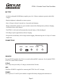
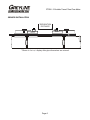
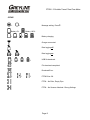
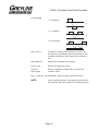
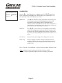
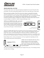
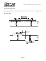
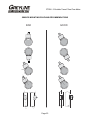
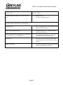
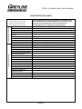
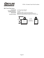
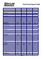
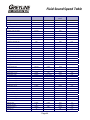
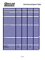
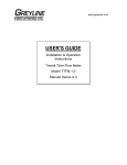
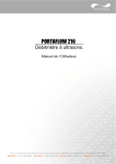
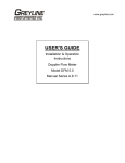
www.greyline.com USER'S GUIDE Installation & Operation Instructions Portable Transit Time Flow Meter Model PTFM 1.0 Manual Series A.1.3 Note: This page has been left blank intentionally. Page 2 PTFM 1.0 Portable Transit Time Flow Meter INDEX BATTERY ................................................................................................................. 4 CONNECTIONS ....................................................................................................... 4 QUICK BENCH TEST.............................................................................................. 5 SENSOR INSTALLATION ...................................................................................... 6 KEYPAD SYSTEM .................................................................................................. 7 CALIBRATION MENU ........................................................................................... 8 ICONS ....................................................................................................................... 9 MESSAGE ................................................................................................................. 10 STATUS .................................................................................................................... 10 PASSWORD.............................................................................................................. 11 UNITS/MODE ........................................................................................................... 12 SET UP ...................................................................................................................... 13 CALIBRATION ........................................................................................................ 15 DATA LOGGING ..................................................................................................... 16 SPECIAL FUNCTIONS ............................................................................................ 17 SENSOR MOUNTING ............................................................................................. 19 FIELD TROUBLESHOOTING ................................................................................ 24 COMMON QUESTIONS AND ANSWERS ............................................................ 26 APPLICATIONS HOTLINE..................................................................................... 28 PRODUCT RETURN PROCEDURE ....................................................................... 29 FLOW METER DATA SHEET ................................................................................ 30 APPENDIX A - CONVERSION TABLE ................................................................. 34 PIPE CHARTS .......................................................................................................... 35 APPENDIX B – Liquid Speed of Sound ................................................................... 39 IMPORTANT NOTE: This instrument is manufactured and calibrated to meet product specifications. Please read this manual carefully before installation and operation. Any unauthorized repairs or modifications may result in a suspension of the warranty. If this product is not used as specified by the manufacturer, protection may be impaired. Available in Adobe Acrobat pdf format. Page 3 PTFM 1.0 Portable Transit Time Flow Meter BATTERY - A built-in rechargable NiMH battery supplies power for 18 hours continuous operation when fully charged. - Display brightness is adjustable to conserve power. - State of charge is shown for normal use, sleep mode and charging. - When switched OFF with the AC power module connected the flashing battery indicates charging, solid battery shows fully charged. - The PTFM 1.0 will switch off automatically when the battery is fully discharged. - Full charge requires approximately 6 hours charging. - Sleep mode extends battery life for long term data logging. Maximum log time is 18 days at 5 minute sample rate. CONNECTIONS TRANSDUCER 15VDC USB 4-20 mA DOWN UP SENSORS Use type SE16B supplied with 12 ft (4 m) coaxial cables and BNC connectors. Set of optional PTXC1 50 ft (15 m) sensor cables available. 4-20mA Active only when powered by AC charger, maximum load 500 ohm. USB Cable Part #USB-PD is supplied for connecting the PTFM 1.0 to a PC or laptop. POWER An AC powered 15 volt DC power module is supplied for battery charging and continuous use. Page 4 PTFM 1.0 Portable Transit Time Flow Meter QUICK BENCH TEST In the PTFM Setup menu set parameters to perform a bench test: - Set Fluid = Water Set Temperature = 20°C Set Pipe OD = 0.15 inch Set Pipe Wall = 0.06 inch Set Pipe material = ABS Set Lining = None Set Crossings = 4 Press to view Signal Strength at bottom of menu. Press twice to exit Setup and return to main display. From main display press to view Status menu. Apply coupling compound to the face of sensors and press together as indicated in the illustration below. The Status menu should indicate Noise low and a high Signal Strength (75-100%). COUPLING COMPOUND ~0.8” 20 mm Page 5 PTFM 1.0 Portable Transit Time Flow Meter SENSOR INSTALLATION *SEPARATION DISTANCE SENSOR SENSOR * Shown in ‘Setup’ display after pipe dimensions are entered. Page 6 PTFM 1.0 Portable Transit Time Flow Meter KEYPAD SYSTEM The following diagram shows the PTFM 1.0 menu system. Arrows show the four directions to leave a menu box. Pressing a corresponding keypad arrow will move to the next item in the direction shown. Move the cursor (highlighted) under numerals and increase or decrease numerals with the and keys. To store calibration values permanently, press the . SLEEP BACK LIGHT Page 7 ON OFF PTFM 1.0 Portable Transit Time Flow Meter CALIBRATION MENU --Units/Mode-------}Mode Flow Linear in Volume USG Time min Temperature C --Setup------------} Sensor Select SE16B Fluid Water Fluid Temp 21.6C Pipe OD 4.5000in Pipe Wall 0.2500in Pipe PVC Lining None Crossings 2 Zero Tare No Sens Space 2.59in Velocity 0.00ft/s Signal Strength 100% --Message----------Data log Logging Log Used 0% Battery 50% Charger Off Sensor Good --24 hr log---------}Date Jul 17/2012 Total 135470.0USG Average 1125.3USG/m Maximum 2725.0USG/m Max Time 08:57:00 Minimum 0.000USG/m Min Time 07:35:00 USG/m 0.000 Tot --Calibration------}20mA at 2500.00USG/m 4mA at 0.000USG/m Min Flow 0.000ft/m Damping 20% --Password---------Password 20130.8USG 0000 --Menu Selections---}Units / Mode Set up Calibration Data Logging Special Functions Simulation Configuration --Data Logging------}Log Site ID 0 Mode Flow Set Date Feb 04/2013 Set Time 11:27:40 Interval 10sec Wrapping NO Log Logging --Special Functions}Language English Reset Totalizer NO Negative Totals NO Cal Constant 1.000 Restore Defaults NO New Password 0000 --Status-----------}Velocity 0.00ft/s Signal Strength 100% --Simulation-------} Test Actual Flow 0.00USG/m 4-20mA Flow 4.00 Charging --Configuration----} Utility 1.25.00 Transit Time 1.03 Logger 1.14S Relays 0 Analog Out 1 Page 8 PTFM 1.0 Portable Transit Time Flow Meter ICONS 1. Message waiting. Press . 2. Battery 0%. 1. 2. Battery 100%. 3. 4. 5. Battery charging. Charger connected. Data logging off. 1. 1. Data logging on. 2. 2. 3. 4. USB file download. File download completed. Download Error. 1. 2. 3. PTFM Echo OK. PTFM – No Echo, Empty Pipe. PTFM – No Sensors Attached / Wrong Settings. Page 9 PTFM 1.0 Portable Transit Time Flow Meter MAIN DISPLAY USG/m 0.000 Tot The main display shows the units selected from the Units/Mode menu, Flow or Velocity rate being measured and TOTALIZER. The PTFM 1.0 will start-up with this display. 20130.8USG Message is waiting. Battery 0% Battery 25% Battery 50% Battery 75% Battery 100% Charger connected. Data logging off. Data logging on. MESSAGE --Message----------Data log Logging Log Used 0% Battery 50% Charger Off Sensor Good --Status-----------}Velocity 0.00ft/s Signal Strength 100% Press from the MAIN display to view error/warning messages provided by the instrument. The Message icon will appear on the MAIN display if error messages are being generated by the instrument. Press to return to the main display. STATUS Press from the MAIN display to view instrument status. Velocity Displayed in ft/sec or m/sec. Signal Strength Displays percentage of signal being received by the ultrasonic sensor. Page 10 PTFM 1.0 Portable Transit Time Flow Meter --24 hr log---------}Date Jul 17/2012 Total 135470.0USG Average 1125.3USG/m Maximum 2725.0USG/m Max Time 08:57:00 Minimum 0.000USG/m Min Time 07:35:00 24 HR LOG --Password---------- PASSWORD Password Press from the MAIN display to view a formatted flow report from instruments with a built-in data logger. Press to scroll down one day or repeatedly to scroll to a specific date. Up to 365 days can be stored. Newest date will overwrite the oldest. Press to return to the main display. 0000 The password (a number from 0000 to 9999) prevents unauthorized access to the Calibration menu. From the Main display press the key to get to Password. Factory default password is 0000 and if it has not been changed press the to proceed to the Menu Selections screen. If a password is required, press to place the cursor under the first digit and or to set the number, then to the second digit, etc. Press or to proceed to the Menu Selections screen. A new password can be stored by going to Special Functions/New Password. Page 11 PTFM 1.0 Portable Transit Time Flow Meter --Units/Mode-------}Mode Flow Linear in Volume USG Time min Temperature C --Units/Mode-------Mode Flow }Linear in ft m mm UNITS/MODE From Mode press the and then the or to select Flow or Velocity. Flow mode displays the flow rate in engineering units (e.g. gpm, litres/sec, etc.) Press the to store your selection then the to the next menu item and to enter. From Linear press the key and then the or to select your units of measurement. Press the to store your selection. Press the key to move the symbol to each subsequent menu item and the to save your selections. Note: the volume selection "bbl" denotes U.S. oil barrel. --Units/Mode-------Mode Linear }Volume USG ft3 bbl L m3 IMG IG USMG Press or to return to the Menu Selections screen. --Units/Mode-------Mode Flow Linear in Volume USG }Time sec day hr min Page 12 PTFM 1.0 Portable Transit Time Flow Meter SET UP PTFM 1.0 V1.25L Set Up xxx --Setup------------} Sensor Select SE16B Fluid Water Fluid Temp 21.6C Pipe OD 4.5000in Pipe Wall 0.2500in Pipe PVC Lining None Crossings 2 Zero Tare No Sens Space 2.59in Velocity 0.00ft/s Signal Strength 100% Set Up Go directly to Set up. Sensor Select Choose SE16B. Fluid Vel When Fluid = Other – Enter the fluid velocity at 25C from table or other reference in units of m/s V/C(@25C) When Fluid = Other – Enter fluid velocity adjustment factor over change in temperature in units of m/s per °C. Fluid Select fluid type. Other will require additional information: Fluid Temp Enter average fluid temperature. Pipe OD Place the cursor under the digits and then or to change the numbers and decimal point. Pipe OD should be entered as the exact outside diameter of the pipe where the sensor is mounted. Refer to the Pipe Charts Appendix in this manual for outside diameter of common pipe types and sizes. Pipe Wall Enter wall thickness. Refer to the Pipe Charts Appendix in this manual for thickness of common pipe materials and sizes. Pipe Vel When pipe = Other – Enter pipe material speed of sound (consult factory). Pipe Select pipe material. Lining Thick When Lining – Enter lining thickness Lining Vel When Lining = Other – Enter speed of sound of lining material. Lining Select Lining material. None represents no liner. Other will require additional information. Page 13 PTFM 1.0 Portable Transit Time Flow Meter Crossings 1 = Z mounting Z 2 = V mounting V 4 = W mounting W Zero Tare To suppress readings or fluctuations at zero flow. Set Calibration/Damping to 5% and under no flow conditions and full pipe select Yes to force readings to zero. Sens Space Displays the calculated sensor spacing. Velocity Displays the measured velocity. Signal Strength Displays magnitude of signal being received by the ultrasonic sensor. Press from the Units/Mode display to return to Menu Selections. NOTE: Sensor separation distance is automatically calculated by the instrument and will be displayed in the Setup menu. Page 14 PTFM 1.0 Portable Transit Time Flow Meter --Calibration------} 20mA at 2500.0 USG/m 4mA at 0.000 USG/m Min Flow 2.262 USG/m Damping 5% CALIBRATION Press the to Calibration and to enter. Use or to position before each menu item and to enter. When settings are completed press to store and return to the Calibration menu. *20mA at Press then or to change the numbers and decimal point. Use this menu to set the corresponding flow rate that will be represented by 20mA analog output. If maximum flow is unknown, enter an estimated flow rate and observe actual flow to determine the correct maximum value. Any velocity or flow rate up to +40 ft/sec (12.2 m/sec) may be selected. *4mA at Press or to set the flow rate corresponding to 4mA analog output. This setting may be left at zero flow (or velocity or can be raised to any value less than the 20mA setting, or lowered to any velocity or corresponding flow rate down to -40 ft/sec (-12.2 m/sec). Min Flow Flow rates below this setting will be displayed as zero flow. Damping Increase damping to stabilize readings under turbulent flow conditions. Decrease for fast response to small changes in flow. Damping is shown in percentage (maximum is 99%). Factory default is 20%. Press from the Units/Mode display to return to Menu Selections. *Note 4-20mA circuitry is only powered by the AC power module. To conserve power this output is not active in battery power mode. Page 15 PTFM 1.0 Portable Transit Time Flow Meter --Data Logging------}Log Site ID 0 Mode Flow Set Date Jul 17/2012 Set Time 11:27:40 Interval 10sec Wrapping NO Log Logging DATA LOGGING Setup Select Data Logging from Menu Selections. Log Site ID Enter a number from 00 to 99. The site ID will become part of the downloaded file name to help distinguish downloads from different instruments. Press to store the setting. Mode Select Velocity (e.g. ft/sec or m/sec). Flow (e.g. USGPM or l/sec). Press to store the setting. Set Date Press or to scroll and select Month, Day and Year. Press to store the setting. Set Time Press or to select the current time in Hours, Minutes and Seconds. Press to store the setting. Interval Press or to select the logging interval. Flow rate reading will be stored at each time interval. Press to store the setting. Wrapping Press or to select YES. Press to store the setting. This enables the logging wrap function. In Wrapping mode the oldest data will be overwritten by the newest. If Wrapping is not enabled the logger will stop when its memory becomes full. Log Select Delete and then Start to apply any changes that have been made to the logger Interval or Mode. The current log file will be erased from memory and a new log file will start. RETRIEVE LOG FILE Install Greyline Logger on your PC or laptop. Refer to the Help menu in the program for detailed instructions. - Connect the PTFM 1.0 to the PC using the supplied USB cable. - Install the USB driver program from the install CD. - Start the Greyline Logger Software. - Select "xxxx scan for USB instruments xxxx" in the drop down window at the top of the main window. PTFM 1.0 will be indicated. - Click the download icon to start transferring data. - Downloaded data appears in a pop-up window. Page 16 PTFM 1.0 Portable Transit Time Flow Meter --Special Functions}Language English Reset Totalizer NO Negative Totals NO Cal Constant 1.000 Restore Defaults NO New Password 0000 SPECIAL FUNCTIONS Language Select English, French or Spanish Reset Totalizer Press and select Yes to erase and restart the totalizer at zero. Negative Totals Select Yes to have reverse flow readings deducted from the totalizer. Select NO to totalize forward flow only and ignore reverse flow. Cal Constant Factory set during calibration. (Refer to the calibration certificate supplied with your instrument.) Restore Defaults Select Yes and press to erase all user settings and return the instrument to factory default settings. New Password Select any number from 0000 to 9999 and press . Default setting of 0000 will allow direct access to the calibration menus. Setting of any password greater than 0000 will require the password to be entered to access the calibration menus. Press to return to Menu Selections. Page 17 PTFM 1.0 Portable Transit Time Flow Meter --Simulation-------} Test Actual Flow 0.00USG/m 4-20mA Flow 4.00 SIMULATION Exercises the 4-20mA. Test Select Maximum and press to simulate maximum Flow or Velocity and to output 20mA to the analog channel. Select Minimum and press to simulate minimum Flow or Velocity and to output 4mA to the analog channel. To simulate measurements between minimum and maximum set Test to Actual and then enter for the flow measurement. The analog output will respond to the simulated value. SLEEP MODE Logging in sleep mode requires a minimum sample time of 30 seconds. Selecting sleep mode for 10 second sampling rate results in instrument always being ‘awake’. BACKLIGHT Three levels of backlight are selectable to conserve power. CHARGING A flashing battery indicates charging. A solid battery indicates fully charged. Page 18 PTFM 1.0 Portable Transit Time Flow Meter SENSOR MOUNTING LOCATION The position of the sensor is one of the most important considerations for accurate Transit Time flow measurement. The same location guidelines apply to Transit Time as most other types of flow meters. Before permanently mounting a Transit Time sensor onsite testing is recommended to determine optimum mounting position. Use the sensor coupling compound (supplied with each Greyline flow meter, or petroleum gel, acoustic compound or electrocardiograph gel). Take several readings around the axis of the pipe and then at several points upstream and downstream from the selected position, checking for consistent readings. Avoid high or low reading areas. Mount the sensors where consistent (average) readings were obtained or continue testing on another pipe section. VERTICAL OR HORIZONTAL PIPE - Vertical pipe runs generally provide evenly distributed flow. On Horizontal pipes and liquids with high concentrations of gas or solids, the sensors should be mounted on the side (1 to 5 o’clock positions) to avoid concentrations of gas at the top of the pipe, or solids at the bottom. 1 TO 5 O'CLOCK POSITION ON HORIZONTAL PIPES VERTICAL PIPE USUALLY HAS EVENLY DISTRIBUTED FLOW VELOCITY INCREASING DEVICES: Generally the sensors must be mounted away from flow disturbances such as valves, pumps, orifice plates, venturis or pipe inlets and discharges which tend to increase flow velocity. Velocity increasing devices often cause cavitation, or rapid release of gas bubbles, and readings both up and downstream may be intermittent or inaccurate. As a guideline, mount the sensor at least 20 diameters upstream or 30 diameters downstream from velocity increasing devices. Required distance from a velocity increasing device will vary in applications depending on the flow velocity and the characteristics of the liquid itself. SENSORS MOUNT 6 DIAMETERS UPSTREAM OR 10 DOWNSTREAM FROM AN ELBOW FLOW TURBULENCE INCREASING DEVICES: Elbows, flanged connections and tees tend to introduce desirable conditions of an evenly distributed flow profile. Sensor mounting 6 pipe diameters upstream and 10 diameters downstream from these disturbances is generally optimum. The sensors are designed to mount longitudinally on a straight section of pipe. Do not attempt to mount it on bends, elbows or fittings. Page 19 PTFM 1.0 Portable Transit Time Flow Meter SENSOR MOUNTING Prepare an area 2" wide by 4" long (50mm x 100mm) for sensor bonding by removing loose paint, scale and rust. The objective of site preparation is to eliminate any discontinuity between the sensor and the pipe wall, which would prevent acoustical coupling. A TMK1 Sensor Mounting Kit is supplied with each Greyline flow meter. It includes recommended coupling compound in a plastic applicator and a stainless steel mounting bracket with adjustable pipe straps. Use the Alignment Bar (included) to align sensor brackets for V and W mode mounting. SENSOR ALIGNMENT BAR PIPE ADJUSTABLE STAINLESS STEEL PIPE CLAMP SENSOR MOUNTING BRACKET Mount the PC16 Mounting Bracket as illustrated on pipes 0.6" / 15 mm OD or larger. Stainless steel bands are included for mounting on pipes up to 30" / 750 mm OD. Additional stainless steel bands (by customer) may be combined to mount on larger pipes. SENSOR MOUNTING BRACKET END VIEW PIPE PIPE Page 20 PTFM 1.0 Portable Transit Time Flow Meter SEPARATION DISTANCE Measure separation distance with a ruler or tape measure. Separation distance is automatically calculated by the PTFM 1.0 based on parameters entered in the Set-up menu. Sens Space is displayed on the Setup menu. SEPARATION DISTANCE SENSOR SENSOR SEPARATION DISTANCE SENSOR SENSOR Page 21 PTFM 1.0 Portable Transit Time Flow Meter SENSOR COUPLING For permanent or temporary bonding, the following are recommended: a) Dow Corning silicon compound #4 (supplied) Additional supply: order Greyline Option CC b) Water-based sonic compound: Order Greyline Option CC30 c) Electrocardiograph gel d) Petroleum gel (Vaseline) The above are arranged in their order of preferred application. d & e are only good for temporary bonding at room temperature. DO NOT USE: Silicon RTV caulking compound (silicon rubber). CO SOR SEN M U PO ND Use the pipe clamp and rail (supplied) as illustrated on previous page or use a loop of electrical tape for temporary mounting. Apply silicon coupling compound #4 to the colored face of the sensor. A bead, similar to toothpaste on a toothbrush, is ideal. Do not overtighten (crush the sensor). COMPOUND The sensor must be fixed securely to the pipe with coupling material between the sensor face and the pipe. Sensor installation with excessive coupling compound can result in gaps or voids in the coupling and cause errors or loss of signal. Insufficient coupling compound will create similar conditions. SENSOR PI P E CLAMP Over time temporary coupling compounds (e.g. Petroleum Gel) may gradually sag away from the sensor resulting in reduced signal strength and finally complete loss of signal. Warm temperatures, moisture and vibration will accelerate this process. Dow Corning Silicone Compound #4 as supplied with the PTFM 1.0 (and available from Greyline Instruments) is recommended for semi-permanent installations. Page 22 PTFM 1.0 Portable Transit Time Flow Meter SENSOR MOUNTING/COUPLING RECOMMENDATIONS GOOD BAD Page 23 PTFM 1.0 Portable Transit Time Flow Meter FIELD TROUBLESHOOTING Corrective Action: Possible Causes: METER READING WHEN THERE IS NO FLOW? Erratic measurement (set damping to 0% to check) due to electrical noise or poor signal quality. Variable Speed Drive interference Set Calibration / Damping to 5% with zero flow use Setup / Tare function. Try adjusting sensor spacing (+/- 10%) and contact Greyline for further assistance. Adjust Calibration / Min Flow setting. Follow Drive manufacturers wiring and Grounding instructions Relocate Flowmeter, Sensors and wiring away from VSD Disconnect and reconnect sensor cables ensuring that cable plugs are properly inserted into terminals and tightened. Calibration Error Review calibration menu. Pipe dimensions and fluid selection/fluid velocity. Lower flow rate than expected Investigate pump/valves. Compare velocity with alternate instrument. Erratic measurement (set damping to 0% to check) due to electrical noise or poor signal quality. Try adjusting sensor spacing (+/- 10%) and contact Greyline for further assistance. Sensor Connections Check sensor connections at PTFM Sensors not mounted to Pipe or mounted improperly Apply coupling compound and mount sensors to pipe with proper sensor spacing. Empty pipe or partially filled Pipe must be fluid filled and acoustically transparent in order to obtain echoes. Sensor cable connections incorrect or loose METER READING LOWER THAN EXPECTED? NO ECHO INDICATION (Icon: No Echo)? Page 24 PTFM 1.0 Portable Transit Time Flow Meter Corrective Action: Possible Causes: Remount sensor Use Dow Corning Silicone #4 Calibration Error Review calibration menu. Pipe dimensions and fluid selection/fluid velocity. Higher flow rate than expected Investigate pump/valves. Compare velocity with alternate instrument. Erratic measurement (set damping to 0% to check) due to electrical noise or poor signal quality. Try adjusting sensor spacing (+/- 10%) and contact Greyline for further assistance. Pipe not Full Verify pipe is full by mounting sensors at top of pipe and check echo icon. No echo if pipe is not full. High viscosity fluid Laminar flow profile due to high viscosity fluid requires an adjustment to Cal Const. Coupling compound washed out, or sensor loose on pipe. METER READING HIGHER THAN EXPECTED? Page 25 PTFM 1.0 Portable Transit Time Flow Meter COMMON QUESTIONS AND ANSWERS The pipe vibrates. Will it affect the flow meter? Common vibration frequencies are far lower than the sonic frequencies used by the Greyline flow meter, and will not normally affect accuracy or performance. However, applications where very weak Transit Time signal is present (when sensitivity is adjusted to maximum and signal strength is low), accuracy may be affected by pipe vibration, or the flow meter may show readings under no-flow conditions. Attempt to relocate the sensor on a pipe section where vibration is reduced, or arrange pipe mounting brackets to reduce vibration at the sensor mounting location. The flow meter must be installed in a high noise environment. Will this affect operation? Greyline flow meters are designed to discriminate between environmental noise and the Transit Time signal. High noise environments may affect the flow meter’s performance where low signal strength and/or low flow velocities are being measured. Relocate the sensor in a quieter environment if possible. Will pipe corrosion affect accuracy of the flow meter? Yes. Rust, loose paint etc. must be removed from the outside of the pipe to provide a clean mounting position when installing a Transit Time sensor. Severe corrosion/oxidation on the inside of the pipe may prevent the Transit Time signal from penetrating into the flow. If the pipe cannot be cleaned, a spool piece (PVC recommended) should be installed for sensor mounting. What effect do pipe liners have on the flow meter? The air gap between loose insertion liners and the pipe wall prevent the Transit Time signal from entering the flow. Better results can be expected with bonded liners such as cement, epoxy or tar, however an on site test is recommended to determine if the application is suitable for a Transit Time flow meter. Why is Transit Time recommended for clean liquids? The Transit Time sensor transmits sound across the flow stream in order to measure sound velocity and therefore requires a fluid medium that is relatively transparent to the acoustic signal. The Transit Time system will not function when there is high volume of solids or aeration. As a guideline, Greyline Transit Time flow meters are recommended for clean liquids with solids or bubbles content less than 2%. Most applications such as water, chemicals and oils will meet this minimum requirement. Can the sensor be submerged in water? Yes, for short periods of time or by accident, but it is not recommended for continuous operation. The sensor is constructed to withstand submersion to 10 psi (0.7 Bar) without damage. Plastic seal jackets on the sensor cables can be filled with coupling compound to provide additional moisture protection for the BNC connectors. Page 26 PTFM 1.0 Portable Transit Time Flow Meter What is the purpose of the Signal Strength Display? The primary function of the signal strength display is to assist as a feedback when mounting sensors. Signal Strength can also be a useful diagnostics tool when troubleshooting problems with an installation. A low signal strength (< 10%) will cause the PTFM to be more susceptible to environmental noise and may indicate a problem with the installation or other qualitative issues. Does the PTFM 1.0 require periodic recalibration? PTFM 1.0 calibration does not normally drift over time. Greyline offers a calibration service to verify instrument accuracy. Can the internal batteries be replaced? The built-in rechargeable NiMH battery pack is not user-serviceable. The meter should be returned to Greyline for battery service. Page 27 PTFM 1.0 Portable Transit Time Flow Meter APPLICATIONS HOTLINE For applications assistance, advice or information on any Greyline Instrument contact your Sales Representative, write to Greyline or phone the Applications Hotline below: United States: Canada: Toll Free: Email: Web Site: Tel: 315-788-9500 Tel: 613-938-8956 888-473-9546 [email protected] www.greyline.com Fax: 315-764-0419 Fax: 613-938-4857 Greyline Instruments Inc. Canada 16456 Sixsmith Drive Long Sault, Ont. K0C 1P0 Page 28 USA: 105 Water Street Massena, NY 13662 PTFM 1.0 Portable Transit Time Flow Meter PRODUCT RETURN PROCEDURE Instruments may be returned to Greyline for service or warranty repair. 1 Obtain an RMA Number from Greyline Before shipping a product to the factory please contact Greyline by telephone, fax or email to obtain an RMA number (Returned Merchandise Authorization). This ensures fast service and correct billing or credit. When you contact Greyline please have the following information available: 1. 2. 3. 4. 5. Model number / Software Version Serial number Date of Purchase Reason for return (description of fault or modification required) Your name, company name, address and phone number 2 Clean the Sensor/Product Important: unclean products will not be serviced and will be returned to the sender at their expense. 1. Rinse sensor and cable to remove debris. 2. If the sensor has been exposed to sewage, immerse both sensor and cable in a solution of 1 part household bleach (Javex, Clorox etc.) to 20 parts water for 5 minutes. Important: do not immerse plug end of sensor cable. 3. Dry with paper towels and pack sensor and cable in a sealed plastic bag. 4. Wipe the outside of the enclosure to remove dirt or deposits. 5. Return to Greyline for service. 3 Ship to Greyline After obtaining an RMA number please ship the product to the appropriate address below: Canadian and International Customers: USA Customers: Greyline Instruments Inc. 16456 Sixsmith Drive Long Sault, Ont. K0C 1P0 Greyline Instruments Inc. 204 150th Avenue Madeira Beach, FL 33708 RMA# RMA# Page 29 PTFM 1.0 Portable Transit Time Flow Meter FLOW METER DATA SHEET [ ] 16456 Sixsmith Drive, Long Sault, ON K0C 1P0 Tel: 613‐938‐8956 / Fax: 613‐938‐4857 [ ] 105 Water Street, Massena, NY 13662 Tel: 315‐788‐9500 / Fax: 315‐764‐0419 Please complete and return this form to Greyline. It is important. We use this information to check our database for performance of Greyline flow meters in similar applications, and to provide advice and recommendations to you. Thank you for your cooperation. Contact Information Contact Title/Dept Company Address Address Tel Fax Email Mobile Pipe Run [ ] Vertical Pipe Full [ ] Yes Fluid Type % of Solids Nominal Pipe Size and Schedule Pipe Outside Diameter Wall Thickness Pipe Material Liner Material Liner Thickness Normal Flow Maximum Flow Minimum Flow Maximum Temperature Maximum Pressure Vibration [ ] Yes Hazardous Rating Notes / Additional Comments / Pipe Run Diagram: [ ] Horizontal [ ] No Service Conditions Page 30 [ ] No PTFM 1.0 Portable Transit Time Flow Meter LIMITED WARRANTY _____________________________________ Greyline Instruments warrants, to the original purchaser, its products to be free from defects in material and workmanship for a period of one year from date of invoice. Greyline will replace or repair, free of charge, any Greyline product if it has been proven to be defective within the warranty period. This warranty does not cover any expenses incurred in the removal and re-installation of the product. If a product manufactured by Greyline should prove defective within the first year, return it freight prepaid to Greyline Instruments along with a copy of your invoice. This warranty does not cover damages due to improper installation or handling, acts of nature, or unauthorized service. Modifications to or tampering with any part shall void this warranty. This warranty does not cover any equipment used in connection with the product or consequential damages due to a defect in the product. All implied warranties are limited to the duration of this warranty. This is the complete warranty by Greyline and no other warranty is valid against Greyline. Some states do not allow limitations on how long an implied warranty lasts or limitation of incidental or consequential damages, so the above limitations or exclusions may not apply to you. This warranty gives you specific legal rights, and you may also have other rights which vary from state to state. Greyline Instruments Inc. Page 31 PTFM 1.0 Portable Transit Time Flow Meter SPECIFICATIONS Flow Rate Range: Pipe Size: Display: Power Input: Outputs: Data Logger: PC Software: Electronics Operating Temperature: Electronics Enclosure: Carry Case: Accuracy: Calibration: Language Selection: Sensitivity: Approvals: 4.33” 110 mm 1.6” 41 mm ± 0.07 to 39 ft/sec (± 0.02 to 12 m/sec) in most applications Ultrasonic Sensor mounts on any pipe from 1/2" to 48" ID (12 mm to 1200 mm) White, backlit matrix - displays flow rate, totalizer, operating mode and calibration menu Built-in NiMH battery for up to 18 8” hours continuous operation 204 mm External charger with 100240VAC 50/60Hz input 4-20mA (500 ohm) when AC powered USB for Data Log transfer by direct PC connection Programmable 300,000 data point capacity, time and date stamped ENCLOSURE or formatted flow reports including total, average, minimum, maximum and times of occurrence 'Greyline Logger' for Windows 98 or higher. Retrieves, displays and saves data log files -5° to 140°F (-20° to 60°C) Portable, ABS enclosure Rated IP67 with protective molded foam insert ±1% of reading or 0.1 ft/sec (0.03 m/sec), whichever is greater. Repeatability: ±0.25%, Linearity: ±0.5% Built-in 5-key programming with user-friendly calibration menu. Password protected. English, French, Spanish Adjustable signal cut-off, signal strength and damping Charger is CE and UL approved. The PTFM 1.0 is not certified for use in hazardous rated locations. Page 32 PTFM 1.0 Portable Transit Time Flow Meter SE16 Transit Time Sensor Pipe Diameter: Operating Temperature: Operating Frequency: Sensor Cable: Submersion Rating: ½” to 48” (12 mm to 1200 mm) -40° to 300°F (-40° to 150°C) 1.28 MHz 12 ft (4 m) with BNC connectors and seal jackets Optional 50 ft (15 m) with BNC connectors and seal jackets Withstands accidental submersion pressure up to 10 psi (0.7 Bar) 56 mm 2.2" 32 mm 1.25" SIDE VIEW 54 mm / 2.1" Page 33 SE16B SENSOR DIMENSIONS END VIEW 30 mm / 1.2" PTFM 1.0 Portable Transit Time Flow Meter APPENDIX A - CONVERSION TABLE CONVERSION GUIDE FROM TO MULTIPLY BY US GALLONS CUBIC FEET 0.1337 US GALLONS IMPERIAL GALS 0.8327 US GALLONS LITRES 3.785 US GALLONS CUBIC METERS 0.003785 LITRES/SEC GPM 15.85 LITRES CUBIC METERS 0.001 BARRELS US GALLONS 42 BARRELS IMPERIAL GALS 34.9726 BARRELS LITRES 158.9886 INCHES MM 25.4 DEGREES F DEGREES C (°F-32) x 0.556 POUNDS KILOGRAMS 0.453 PSI BAR 0.0676 FOOT² METER² 0.0929 Note: BARRELS are U.S. oil barrels. Page 34 PTFM 1.0 Portable Transit Time Flow Meter PIPE CHARTS Carbon Steel & PVC Pipe Pipe Pipe Standard Extra Heavy Dbl. Extra Heavy Schedule 10 Size O.D. I.D. WALL I.D. WALL I.D. WALL I.D. WALL ½ .840 .622 .109 .546 .147 .252 .294 .622 .109 ¾ 1.050 .824 .113 .742 .154 .434 .308 .824 .113 1 1.315 1.049 .133 .957 .179 .599 .358 1.049 .133 1¼ 1.660 1.380 .140 1.278 .191 .896 .382 1.380 .140 1½ 1.900 1.610 .145 1.500 .200 1.100 .400 1.610 .145 2 2.375 2.067 .154 1.939 .218 1.503 .436 2.067 .154 2½ 2.875 2.469 .203 2.323 .276 1.771 .552 2.469 .203 I.D. WALL Schedule 20 Schedule 30 I.D. I.D. WALL WALL Schedule 40 3 3.500 3.068 .216 2.900 .300 2.300 .600 3.068 .216 3½ 4.000 3.548 .226 3.364 .318 2.728 .636 3.548 .226 4 4.500 4.026 .237 3.826 .337 3.152 .674 4.026 .237 5 5.563 5.047 .258 4.813 .375 4.063 .750 5.047 .258 6 6.625 6.065 .280 5.761 .432 4.897 .864 6.065 .280 8 8.625 7.981 .322 7.625 .500 6.875 .875 8.125 .250 8.071 .277 7.981 .322 10 10.750 10.020 .365 9.750 .500 8.750 1.000 10.250 .250 10.136 .307 10.020 .365 12 12.750 12.000 .375 11.750 .500 10.750 1.000 12.250 .250 12.090 .330 11.938 .406 14 14.000 13.250 .375 13.000 .500 13.500 .250 13.376 .312 13.250 .375 13.124 .438 16 16.000 15.250 .375 15.000 .500 15.500 .250 15.376 .312 15.250 .375 15.000 .500 18 18.000 17.250 .375 17.000 .500 17.500 .250 17.376 .312 17.124 .438 16.876 .562 20 20.000 19.250 .375 19.000 .500 19.500 .250 19.250 .375 19.000 .500 18.814 .593 22 22.000 21.250 .375 21.000 .500 21.500 .250 21.250 .375 21.000 .500 24 24.000 23.250 .375 23.000 .500 23.500 .250 23.250 .375 22.876 .562 22.626 .687 26 26.000 25.250 .375 25.000 .500 25.376 .312 25.000 .500 28 28.000 27.250 .375 27.000 .500 27.376 .312 27.000 .500 26.750 .625 30 30.000 29.250 .375 29.000 .500 29.376 .312 29.000 .500 28.750 .625 32 32.000 31.250 .375 31.000 .500 31.376 .312 31.000 .500 30.750 .625 34 34.000 33.250 .375 33.000 .500 33.376 .312 33.000 .500 32.750 .625 36 36.000 35.250 .375 35.000 .500 35.376 .312 35.000 .500 34.750 .625 42 42.000 41.250 .375 41.000 .500 41.000 .500 40.750 .625 Ductile Ir on Pipe - Standard Classes Size OUTSIDE Clas s Class Class C lass C lass C lass C la ss IN CH D IA. 50 51 52 53 54 55 56 INC H WA LL I.D. C EMEN T LIN IN G WA LL I.D. WA LL I.D. WA LL I.D. WA LL I.D. WA LL I.D. WA LL I.D. 3 3.96 0 .2 5 3 .4 6 0 .2 8 3 .4 0 0 .3 1 3 .3 4 0 .3 4 3 .2 8 0 .3 7 3 .2 2 0 .4 1 3 .1 4 4 6 4.80 6.90 0 .2 5 6 .40 0 .2 6 0 .2 8 4 .2 8 6 .3 4 0 .2 9 0 .3 1 4 .2 2 6 .2 8 0 .3 2 0 .3 4 4 .1 6 6 .2 2 0 .3 5 0 .3 7 4 .1 0 6 .1 6 0 .3 8 0 .4 0 4 .0 4 6 .1 0 0 .4 4 0 .4 3 3 .9 3 6 .0 4 8 10 12 9.05 11 .1 0 13 .2 0 0 .2 7 0 .3 9 0 .3 1 8 .51 10 .3 2 12 .5 8 0 .3 0 0 .3 2 0 .3 4 8 .4 5 10.4 6 12.5 2 0 .3 3 0 .3 5 0 .3 7 8 .3 9 10.4 0 12.4 6 0 .3 6 0 .3 8 0 .4 0 8 .3 3 10.3 4 12.4 0 0 .3 9 0 .4 1 0 .4 3 8 .2 7 10.28 12.34 0 .4 2 0 .4 4 0 .4 6 8 .2 1 10.22 12.28 0 .4 5 0 .4 7 0 .4 9 8 .1 5 10.16 12.22 14 15 .3 0 0 .3 3 14 .6 4 0 .3 6 14.5 8 0 .3 9 14.5 2 0 .4 2 14.4 6 0 .4 5 14.40 0 .4 8 14.34 0 .5 1 14.28 16 18 17 .4 0 19 .5 0 0 .3 4 0 .3 5 16 .7 2 18 .8 0 0 .3 7 0 .3 8 16.6 6 18.7 4 0 .4 0 0 .4 1 16.6 0 18.6 8 0 .4 3 0 .4 4 16.5 4 18.6 2 0 .4 6 0 .4 7 16.48 18.56 0 .4 9 0 .5 0 16.42 18.50 0 .5 2 0 .5 3 16.36 18.44 20 24 21 .6 0 25 .8 0 0 .3 6 0 .3 8 20 .8 8 25 .0 4 0 .3 9 0 .4 1 20.8 2 24.9 8 0 .4 2 0 .4 4 20.7 6 24.9 2 0 .4 5 0 .4 7 20.7 0 24.8 6 0 .4 8 0 .5 0 20.64 24.80 0 .5 1 0 .5 3 20.58 24.74 0 .5 4 0 .5 6 20.52 24.68 30 32 .0 0 0 .3 9 31 .2 2 0 .4 3 31.1 4 0 .4 7 31.0 6 0 .5 1 30.9 8 0 .5 5 30.90 0 .5 9 30.82 0 .6 3 30.74 36 42 38 .3 0 44 .5 0 0 .4 3 0 .4 7 37 .4 4 43 .5 6 0 .4 8 0 .5 3 37.3 4 43.4 4 0 .6 2 0 .5 9 37.0 6 43.3 2 0 .5 8 0 .6 5 37.1 4 43.2 0 0 .6 3 0 .7 1 37.04 43.08 0 .6 8 0 .7 7 36.94 42.96 0 .7 3 0 .8 3 36.84 42.84 48 50 .8 0 0 .5 1 49 .7 8 0 .5 8 49.6 4 0 .6 5 49.5 0 0 .7 2 49.3 6 0 .7 9 49.22 0 .8 6 49.08 0 .9 3 48.94 54 57 .1 0 0 .5 7 55 .9 6 0 .6 5 **R EDU CE I.D . BY DIMEN SION SH OWN 55.8 0 0 .7 3 55.6 4 0 .8 1 55.4 8 0 .8 9 55.32 0 .9 7 55.16 1 .0 5 55.00 Page 35 **S TD ** DOUB LE THIC KNES S TH IC KN ESS .12 5 .25 0 .1 875 .37 5 .25 0 .50 0 PTFM 1.0 Portable Transit Time Flow Meter Stainless Steel, Hastelloy "C" & Titanium Pipe Pipe Pipe Size ½ ¾ 1 1¼ 1½ 2 2½ 3 3½ 4 5 6 8 10 12 14 16 18 20 22 24 O.D. .840 1.050 1.315 1.660 1.900 2.375 2.875 3.500 4.000 4.500 5.563 6.625 8.625 10.750 12.750 14.000 16.000 18.000 20.000 22.000 24.000 Pipe Pipe Size ½ ¾ 1 1¼ 1½ 2 2½ 3 3½ 4 5 6 8 10 12 14 16 18 20 22 24 O.D. .840 1.050 1.315 1.660 1.900 2.375 2.875 3.500 4.000 4.500 5.563 6.625 8.625 10.750 12.750 14.000 16.000 18.000 20.000 22.000 24.000 Scheule 5 S (a) I.D. .710 .920 1.185 1.530 1.770 2.245 2.709 3.334 3.834 4.334 5.345 6.407 8.407 10.482 12.438 13.688 15.670 17.670 19.634 21.624 23.563 Schedule 60 I.D. 7.813 9.750 11.626 12.814 14.688 16.500 18.376 20.250 22.064 Schedule 10 S (a) WALL .065 .065 .065 .065 .065 .065 .083 .083 .083 .083 .109 .109 .109 .134 .156 .156 .165 .165 .188 .188 .218 WALL .406 .500 .562 .593 .656 .750 .812 .875 .968 I.D. .674 .884 1.097 1.442 1.682 2.157 2.635 3.260 3.760 4.260 5.295 6.357 8.329 10.420 12.390 13.624 15.624 17.624 19.564 21.564 23.500 Schedule 80 I.D. .546 .742 .957 1.278 1.500 1.939 2.323 2.900 3.364 3.826 4.813 5.761 7.625 9.564 11.376 12.500 14.314 16.126 17.938 19.750 21.564 WALL .147 .154 .179 .191 .200 .218 .276 .300 .318 .337 .375 .432 .500 .593 .687 .750 .843 .937 1.031 1.125 1.218 Schedule 40 S WALL .083 .083 .109 .109 .109 .109 .120 .120 .120 .120 .134 .134 .148 .165 .180 .188 .188 .188 .218 .218 .250 I.D. .622 .824 1.049 1.380 1.610 2.067 2.469 3.068 3.548 4.026 5.047 6.065 7.981 10.020 12.000 Schedule 80 S WALL .109 .113 .133 .140 .145 .154 .203 .216 .226 .237 .258 .280 .322 .365 .375 I.D. .546 .742 .957 1.278 1.500 1.939 2.323 2.900 3.364 3.826 4.813 5.761 7.625 9.750 11.750 WALL .147 .154 .179 .191 .200 .218 .276 .300 .318 .337 .375 .432 .500 .500 .500 Schedule 100 Schedule 120 Schedule 140 Schedule 160 I.D. WALL I.D. WALL I.D. I.D. .466 .614 .815 1.160 1.338 1.689 2.125 2.624 WALL .187 .218 .250 .250 .281 .343 .375 .438 .593 .718 .843 .937 1.031 1.156 1.281 1.375 1.531 3.624 4.563 5.501 7.189 9.064 10.750 11.814 13.564 15.250 17.000 18.750 20.376 .438 .500 .562 .718 .843 1.000 1.093 1.218 1.375 1.500 1.625 1.812 3.438 4.313 5.189 6.813 8.500 10.126 11.188 12.814 14.438 16.064 17.750 19.314 .531 .625 .718 .906 1.125 1.312 1.406 1.593 1.781 1.968 2.125 2.343 7.439 9.314 11.064 12.126 13.938 15.688 17.438 19.250 20.938 Page 36 7.001 8.750 10.500 11.500 13.124 14.876 16.500 18.250 19.876 WALL .812 1.000 1.125 1.250 1.438 1.562 1.750 1.875 2.062 PTFM 1.0 Portable Transit Time Flow Meter Cast Iron Pipe - ASA Standard Pipe Pipe Size 3 4 6 8 10 12 14 16 18 20 24 O.D. 3.96 4.80 6.90 9.05 11.10 13.20 15.30 17.40 19.50 21.60 25.80 Class 50 WALL 0.32 0.35 0.38 0.41 0.44 0.48 0.48 0.54 0.54 0.57 0.63 Class 100 I.D. 3.32 4.10 6.14 8.23 10.22 12.24 14.34 16.32 18.42 20.46 24.54 WALL 0.32 0.35 0.38 0.41 0.44 0.48 0.51 0.54 0.58 0.62 0.68 Class 150 I.D. 3.32 4.10 6.14 8.23 10.22 12.24 14.28 16.32 18.34 20.36 24.44 WALL 0.32 0.35 0.38 0.41 0.44 0.48 0.51 0.54 0.58 0.62 0.73 I.D. 3.32 4.10 6.14 8.23 10.22 12.24 14.28 16.32 18.34 20.36 24.34 Class 200 WALL 0.32 0.35 0.38 0.41 0.44 0.48 0.55 0.58 0.63 0.67 0.79 Class 250 I.D. 3.32 4.10 6.14 8.23 10.22 12.24 14.20 16.24 18.24 20.26 24.22 WALL 0.32 0.35 0.38 0.41 0.44 0.52 0.59 0.63 0.68 0.72 0.79 I.D. 3.32 4.10 6.14 8.23 10.22 12.16 14.12 16.14 18.14 20.16 24.22 Class 300 WALL 0.32 0.35 0.38 0.41 0.48 0.52 0.59 0.68 0.73 0.78 0.85 Class 350 I.D. 3.32 4.10 6.14 8.23 10.14 12.16 14.12 16.04 18.04 20.04 24.10 WALL 0.32 0.35 0.38 0.41 0.52 0.56 0.64 0.68 0.79 0.84 0.92 I.D. 3.32 4.10 6.14 8.23 10.06 12.08 14.02 16.04 17.92 19.92 23.96 Cast Iron Pipe - AWWA Standard Pipe Size 3 4 6 8 10 12 14 16 18 20 24 30 36 42 48 54 60 72 84 O.D. 3.80 4.80 6.90 9.05 11.10 13.20 15.30 17.40 19.50 21.60 25.80 31.74 37.96 44.20 50.50 56.66 62.80 75.34 87.54 Pipe Size 6 8 10 12 14 16 18 20 24 30 36 O.D. 7.22 9.42 11.60 13.78 15.98 18.16 20.34 22.54 26.90 33.10 39.60 Class A Class B Class C Class D 100 Ft. 43 PSIG 200 Ft. 86 PSIG 300 Ft. 130 PSIG 400 Ft. 173 PSIG WALL 0.39 0.42 0.44 0.46 0.50 0.54 0.57 0.60 0.64 0.67 0.76 0.88 0.99 1.10 1.26 1.35 1.39 1.62 1.72 I.D. 3.02 3.96 6.02 8.13 10.10 12.12 14.16 16.20 18.22 20.26 24.28 29.98 35.98 42.00 47.98 53.96 60.02 72.10 84.10 O.D. 3.96 5.00 7.10 9.05 11.10 13.20 15.30 17.40 19.50 21.60 25.80 32.00 38.30 44.50 50.80 57.10 63.40 76.00 88.54 WALL 0.42 0.45 0.48 0.51 0.57 0.62 0.66 0.70 0.75 0.80 0.89 1.03 1.15 1.28 1.42 1.55 1.67 1.95 2.22 I.D. 3.12 4.10 6.14 8.03 9.96 11.96 13.98 16.00 18.00 20.00 24.02 29.94 36.00 41.94 47.96 54.00 60.06 72.10 84.10 O.D. 3.96 5.00 7.10 9.30 11.40 13.50 15.65 17.80 19.92 22.06 26.32 32.40 38.70 45.10 51.40 57.80 64.20 76.88 WALL 0.45 0.48 0.51 0.56 0.62 0.68 0.74 0.80 0.87 0.92 1.04 1.20 1.36 1.54 1.71 1.90 2.00 2.39 I.D. 3.06 4.04 6.08 8.18 10.16 12.14 14.17 16.20 18.18 20.22 24.22 30.00 39.98 42.02 47.98 54.00 60.20 72.10 O.D. 3.96 5.00 7.10 9.30 11.40 13.50 15.65 17.80 19.92 22.06 26.32 32.74 39.16 45.58 51.98 58.40 64.82 WALL 0.48 0.52 0.55 0.60 0.68 0.75 0.82 0.89 0.96 1.03 1.16 1.37 1.58 1.78 1.96 2.23 2.38 I.D. 3.00 3.96 6.00 8.10 10.04 12.00 14.01 16.02 18.00 20.00 24.00 30.00 36.00 42.02 48.06 53.94 60.06 Class E Class F Class G Class H 500 Ft. 217 PSIG 600 Ft. 260 PSIG 700 Ft. 304 PSIG 800 Ft. 347 PSIG WALL 0.58 0.66 0.74 0.82 0.90 0.98 1.07 1.15 1.31 1.55 1.80 I.D. 6.06 8.10 10.12 12.14 14.18 16.20 18.20 20.24 24.28 30.00 36.00 O.D. 7.22 9.42 11.60 13.78 15.98 18.16 20.34 22.54 26.90 33.46 40.04 WALL 0.61 0.71 0.80 0.89 0.99 1.08 1.17 1.27 1.45 1.73 2.02 I.D. 6.00 8.00 10.00 12.00 14.00 16.00 18.00 20.00 24.00 30.00 36.00 O.D. 7.38 9.60 11.84 14.08 16.32 18.54 20.78 23.02 27.76 Page 37 WALL 0.65 0.75 0.86 0.97 1.07 1.18 1.28 1.39 1.75 I.D. 6.08 8.10 10.12 12.14 14.18 16.18 18.22 20.24 24.26 O.D. 7.38 9.60 11.84 14.08 16.32 18.54 20.78 23.02 27.76 WALL 0.69 0.80 0.92 1.04 1.16 1.27 1.39 1.51 1.88 I.D. 6.00 8.00 10.00 12.00 14.00 16.00 18.00 20.00 24.00 PTFM 1.0 Portable Transit Time Flow Meter Copper Tubing Pipe K L M Copper & Brass Pipe Size O.D. I.D. WALL O.D. I.D. WALL O.D. I.D. WALL O.D. I.D. WALL ½" ⅝" ¾" 1" 0.625 0.750 0.875 1.125 0.527 0.652 0.745 0.995 0.049 0.049 0.065 0.065 0.625 0.750 0.875 1.125 0.545 0.666 0.785 1.025 0.040 0.042 0.045 0.050 0.625 0.750 0.875 1.125 0.569 0.690 0.811 1.055 0.028 0.030 0.032 0.035 0.840 0.625 0.108 1.050 1.315 0.822 1.062 0.114 0.127 1 ¼" 1 ½" 2" 2½ 1.375 1.625 2.125 2.625 1.245 1.481 1.959 2.435 0.065 0.072 0.083 0.095 1.375 1.625 2.125 2.625 1.265 1.505 1.985 2.465 0.055 0.060 0.070 0.080 1.375 1.625 2.125 2.625 1.291 1.527 2.009 2.495 0.042 0.049 0.058 0.065 1.660 1.900 2.375 2.875 1.368 1.600 2.062 2.500 0.146 0.150 0.157 0.188 3" 3 ½" 4" 4 ½" 3.125 3.625 4.125 2.907 3.385 3.857 0.109 0.120 0.134 3.125 3.625 4.125 2.945 3.425 3.905 0.090 0.100 0.110 3.125 3.625 4.125 2.981 3.459 3.935 0.072 0.083 0.095 3.500 4.000 4.500 3.062 3.500 3.935 0.219 0.250 0.095 5" 6" 7" 8" 5.125 6.125 4.805 5.741 0.160 0.192 5.125 6.125 4.875 5.845 0.125 0.140 5.125 6.125 4.907 5.881 0.109 0.122 8.125 7.583 0.271 8.125 7.725 0.200 8.125 7.785 0.170 5.563 6.625 7.625 8.625 5.063 6.125 7.062 8.000 0.250 0.250 0.282 0.313 10" 12" 10.125 12.125 9.449 11.315 0.338 0.405 10.125 12.125 9.625 11.565 0.250 0.280 10.125 12.125 9.701 11.617 0.212 0.254 10.000 9.812 0.094 Page 38 Aluminum O.D. I.D. WALL 2.500 2.400 0.050 3.000 2.900 0.050 4.000 5.000 4.000 4.500 0.250 0.250 5.000 6.000 7.000 8.000 4.874 5.874 6.844 7.812 0.063 0.063 0.078 0.094 Fluid Sound Speed Table APPENDIX B – Liquid Speed of Sound Substance Form Index Specific Gravity Sound Speed m/sec. v/°C - m/s/°C ∆ Acetic anhydride (22) (CH3CO)2O 1.082 (20ºC) 1180 2.5 Acetic acid, anhydride (22) (CH3CO)2O 1.082 (20ºC) 1180 2.5 Acetic acid, nitrile C2H3N 0.783 1290 4.1 Acetic acid, ethyl ester (33) C4H8O2 0.901 1085 4.4 Acetic acid, methyl ester C3H6O2 0.934 1211 Acetone C3H6O 0.791 1174 4.5 Acetonitrile C2H3N 0.783 1290 4.1 Acetonylacetone C6H10O2 0.729 1399 3.6 Acetylene dichloride C2H2Cl2 1.26 1015 3.8 Acetylene tetrabromide (47) C2H2Br4 2.966 1027 Acetylene tetrachloride (47) C2H2Cl4 1.595 1147 Alcohol C2H6O 0.789 1207 4.0 Alkazene-13 C15H24 0.86 1317 3.9 Alkazene-25 C10H12Cl2 1.20 1307 3.4 C2H7NO 1.018 1724 3.4 2-Aminotolidine (46) C7H9N 0.999 (20ºC) 1618 4-Aminotolidine (46) C7H9N 0.966 (45ºC) 1480 NH3 0.771 1729 0.98 962.6 2-Amino-ethanol Ammonia (35) Amorphous Polyolefin t-Amyl alcohol 6.68 C5H12O 0.81 1204 Aminobenzene (41) C6H5NO2 1.022 1639 4.0 Aniline (41) C6H5NO2 1.022 1639 4.0 Argon (45) Ar 1.400 (-188ºC) 853 Azine C6H5N 0.982 1415 4.1 Benzene (29,40,41) C6H6 0.879 1306 4.65 Benzol(29,40,41) C6H6 0.879 1306 4.65 3.0 Bromine (21) Br2 2.928 889 Bromo-benzene (46) C6H5Br 1.522 1170 1-Bromo-butane (46) C4H9Br 1.276 (20ºC) 1019 Bromo-ethane (46) C2H5Br 1.460 (20ºC) 900 Bromoform (46,47) CHBr3 2.89 (20ºC) 918 n-Butane (2) C4H10 0.601 (0ºC) 1085 5.8 2-Butanol C4H10O 0.81 1240 3.3 sec-Butylalcohol C4H10O 0.81 1240 3.3 n-Butyl bromide (46) C4H9Br 1.276 (20ºC) 1019 n-Butyl chloride (22,46) C4H9Cl 0.887 1140 4.57 tert Butyl chloride C4H9Cl 0.84 984 4.2 1404 3.0 1484 1.51 Butyl oleate C22H42O2 2,3 Butylene glycol C4H10O2 Cadmium (7) Carbinol (40,41) 1.019 Cd 2237.7 CH4O 0.791 (20ºC) 1076 C6H14O3 0.988 1458 Carbon dioxide (26) CO2 1.101 (-37ºC) 839 Carbon disulphide CS2 1.261 (22ºC) 1149 Carbon tetrachloride(33,35,47) CCl4 1.595 (20ºC) 926 Carbitol 3.1 2.92 7.71 2.48 Fluid Sound Speed Table Substance Carbon tetrafluoride (14) Form Index Specific Gravity Sound Speed m/sec. v/°C - m/s/°C ∆ CF4 1.75 (-150ºC) 875.2 6.61 Cetane (23) C16H34 0.773 (20ºC) 1338 3.71 Chloro-benezene C6H5Cl 1.106 1273 3.6 1-Chloro-butane (22,46) C4H9Cl 0.887 1140 4.57 Chloro-diFluoromethane (3) (Freon 22) CHClF2 1.491 (-69ºC) 893.9 4.79 Chloroform (47) CHCl3 1.489 979 3.4 1-Chloro-propane (47) C3H7Cl 0.892 1058 Chlorotrifluoromethane (5) CClF3 724 5.26 Cinnamaldehyde C9H8O 1.112 1554 3.2 Cinnamic aldehyde C9H8O 1.112 1554 3.2 C2H7NO 1.018 1724 3.4 o-Cresol (46) C7H8O 1.047 (20ºC) 1541 m-Cresol (46) C7H8O 1.034 (20ºC) 1500 Cyanomethane C2H3N 0.783 1290 4.1 Cyclohexane (15) C6H12 0.779 (20ºC) 1248 5.41 Cyclohexanol C6H12O 0.962 1454 3.6 Cyclohexanone C6H10O 0.948 1423 4.0 Decane (46) C10H22 0.730 1252 1-Decene (27) C10H20 0.746 1235 n-Decylene (27) C10 H20 0.746 1235 4.0 Diacetyl C4H6O2 0.99 1236 4.6 Diamylamine C10H23N 1256 3.9 1,2 Dibromo-ethane (47) C2H4Br2 2.18 trans-1,2-Dibromoethene(47) C2H2Br2 2.231 Dibutyl phthalate C8H22O4 1408 Dichloro-t-butyl alcohol C4H8Cl2O 1304 3.8 2,3 Dichlorodioxane C2H6Cl2O2 1391 3.7 4.24 Colamine 4.0 995 935 Dichlorodifluoromethane (3) (Freon 12) CCl2F2 1.516 (-40ºC) 774.1 1,2 Dichloro ethane (47) C2H4Cl2 1.253 1193 cis 1,2-Dichloro-Ethene(3,47) C2H2Cl2 1.284 1061 trans 1,2-Dichloro-ethene(3,47) C2H2Cl2 1.257 1010 Dichloro-fluoromethane (3) (Freon 21) CHCl2F 1.426 (0ºC) 891 1-2-Dichlorohexafluoro cyclobutane (47) C4Cl2F6 1.654 669 1-3-Dichloro-isobutane C4H8Cl2 1.14 1220 3.4 Dichloro methane (3) CH2Cl2 1.327 1070 3.94 1,1-Dichloro-1,2,2,2 tetra fluoroethane 3.97 CClF2-CClF2 1.455 665.3 3.73 Diethyl ether C4H10O 0.713 985 4.87 Diethylene glycol, monoethyl ether C6H14O3 0.988 1458 Diethylenimide oxide C4H9NO 1.00 1442 1,2-bis(DiFluoramino) butane (43) C4H8(NF2)2 1.216 1000 1,2bis(DiFluoramino)- 2-methylpropane (43) 1,2bis(DiFluoramino) propane (43) C4H9(NF2)2 1.213 900 C3H6(NF2)2 1.265 960 2,2bis(DiFluoramino) propane (43) C3H6(NF2)2 1.254 890 C4H10O3 1.116 1586 2,2-Dihydroxydiethyl ether Page 40 3.8 2.4 Fluid Sound Speed Table Substance Dihydroxyethane Form Index Specific Gravity Sound Speed m/sec. v/°C - m/s/°C ∆ 2.1 C2H6O2 1.113 1658 1,3-Dimethyl-benzene (46) C8H10 0.868 (15ºC) 1343 1,2-1.0Dimethyl-benzene(29,46) C8H10 0.897 (20ºC) 1331.5 1,4-Dimethyl-benzene (46) C8H10 2,2-Dimethyl-butane (29,33) C6H14 0.649 (20ºC) Dimethyl ketone C3H6O 0.791 1174 Dimethyl pentane (47) C7H16 0.674 1063 C8H10O4 1.2 1463 CH2I2 3.235 980 C4H8O2 1.033 1376 Dodecane (23) C12H26 0.749 1279 3.85 1,2-Ethanediol C2H6O2 1.113 1658 2.1 Ethanenitrile C2H3N 0.783 1290 (CH3CO)2O 1.082 1180 Dimethyl phthalate Diiodo-methane Dioxane Ethanoic anhydride (22) Ethanol 4.1 1334 1079 4.5 C2H6O 0.789 1207 4.0 Ethanol amide C2H7NO 1.018 1724 3.4 Ethoxyethane C4H10O 0.713 985 4.87 Ethyl acetate (33) C4H8O2 0.901 1085 4.4 Ethyl alcohol C2H6O 0.789 1207 4.0 Ethyl benzene (46) C8H10 0.867(20ºC) 1338 Ethyl bromide (46) C2H5Br 1.461 (20ºC) 900 C2H5I 1.950 (20ºC) 876 Ether C4H10O 0.713 985 4.87 Ethyl ether C4H10O 0.713 985 4.87 Ethylene bromide (47) C2H4Br2 2.18 995 Ethylene chloride (47) C2H4Cl2 1.253 1193 Ethylene glycol C2H6O2 1.113 1658 Ethyliodide (46) 50% Glycol/ 50% H2O d-Fenochone C10H16O 0.947 1320 d-2-Fenechanone C10H16O 0.947 1320 Fluorine 2.1 1578 F 0.545 (-143ºC) 403 Fluoro-benzene (46) C6H5F 1.024 (20ºC) 1189 Formaldehyde, methyl ester C2H4O2 0.974 1127 4.02 Formamide CH3NO 1.134 (20ºC) 1622 2.2 Formic acid, amide CH3NO 1.134 (20ºC) 1622 Freon R12 11.31 774 Furfural C5H4O2 1.157 1444 Furfuryl alcohol C5H6O2 1.135 1450 3.4 Fural C5H4O2 1.157 1444 3.7 2-Furaldehyde C5H4O2 1.157 1444 3.7 2-Furancarboxaldehyde C5H4O2 1.157 1444 3.7 2-Furyl-Methanol C5H6O2 1.135 1450 3.4 Gallium Ga 6.095 2870 (@30ºC) Glycerin C3H8O3 1.26 1904 Page 41 2.2 Fluid Sound Speed Table Substance Form Index Specific Gravity Sound Speed m/sec. v/°C - m/s/°C ∆ Glycerol C3H8O3 1.26 1904 2.2 Glycol C2H6O2 1.113 1658 2.1 He4 0.125(-268.8ºC) 183 Heptane (22,23) C7H16 0.684 (20ºC) 1131 4.25 n-Heptane (29,33) C7H16 0.684 (20ºC) 1180 4.0 Helium (45) Hexachloro-Cyclopentadiene(47) C5Cl6 1.7180 1150 Hexadecane (23) C16H34 0.773 (20ºC) 1338 Hexalin C6H12O 0.962 1454 3.6 C6H14 0.659 1112 2.71 n-Hexane (29,33) C6H14 0.649 (20ºC) 1079 4.53 2,5-Hexanedione C6H10O2 0.729 1399 3.6 n-Hexanol C6H14O 0.819 1300 3.8 5.41 Hexane (16,22,23) Hexahydrobenzene (15) 3.71 C6H12 0.779 1248 C6H12O 0.962 1454 3.6 C6H12 0.779 1248 5.41 H2 0.071 (-256ºC) 1187 2-Hydroxy-toluene (46) C7H8O 1.047 (20ºC) 1541 3-Hydroxy-tolune (46) C7H8O 1.034 (20ºC) 1500 Iodo-benzene (46) C6H5I 1.823 1114 Iodo-ethane (46) C2H5I 1.950 (20ºC) 876 CH3I 2.28 (20ºC) Hexahydrophenol Hexamethylene (15) Hydrogen (45) Iodo-methane Isobutyl acetate (22) C6H12O Isobutanol C4H10O 978 1180 0.81 (20ºC) Iso-Butane 4.85 1212 1219.8 Isopentane (36) C5H12 0.62 (20ºC) 980 Isopropanol (46) C3H8O 0.785 (20ºC) 1170 Isopropyl alcohol (46) C3H8O 0.785 (20ºC) 1170 0.81 1324 0.948 1423 4.0 2485 1.29 Kerosene Ketohexamethylene C6H10O Lithium fluoride (42) LiF Mercury (45) Hg 13.594 1449 Mesityloxide C6H16O 0.85 1310 Methane (25,28,38,39) 4.8 3.6 CH4 0.162 405(-89.15ºC) 17.5 CH4O 0.791 (20ºC) 1076 2.92 Methyl acetate C3H6O2 0.934 1211 o-Methylaniline (46) C7H9N 0.999 (20ºC) 1618 4-Methylaniline (46) C7H9N 0.966 (45ºC) 1480 Methyl alcohol (40,44) CH4O 0.791 (20ºC) 1076 2.92 Methyl benzene (16,52) C7H8 0.867 1328 4.27 2-Methyl-butane (36) C5H12 0.62 (20ºC) 980 Methyl carbinol C2H6O 0.789 1207 Methyl-chloroform (47) C2H3Cl3 1.33 985 Methyl-cyanide C2H3N 0.783 1290 3-Methyl cyclohexanol C7H14O 0.92 1400 Methanol (40,41) Page 42 4.0 Fluid Sound Speed Table Substance Form Index Specific Gravity Sound Speed m/sec. v/°C - m/s/°C ∆ CH2Cl2 1.327 1070 3.94 CH2I2 3.235 980 C2H4O2 0.974 (20ºC) 1127 CH3I 2.28 (20ºC) 978 2-Methylphenol (46) C7H8O 1.047 (20ºC) 1541 3-Methylphenol (46) C7H8O 1.034 (20ºC) Methylene chloride (3) Methylene iodide Methyl formate (22) Methyl iodide Milk, homogenized Morpholine C4H9NO Natural Gas (37) Nitrobenzene (46) Nitrogen (45) Nitromethane (43) 1500 1548 Naphtha Neon (45) 4.02 1.00 1442 0.76 1225 0.316 (-103ºC) 753 Ne 1.207 (-246ºC) 595 C6H5NO2 1.204 (20ºC) 1415 N2 0.808 (-199ºC) 962 3.8 CH3NO2 1.135 1300 4.0 Nonane (23) C9H2O 0.718 (20ºC) 1207 4.04 1-Nonene (27) C9H18 0.736 (20ºC) 1207 4.0 Octane (23) C8H18 0.703 1172 4.14 n-Octane (29) C8H18 0.704 (20ºC) 1212.5 3.50 1-Octene (27) C8H16 0.723 (20ºC) 1175.5 4.10 1390 3.8 Oil of Camphor Sassafrassy Oil, Car (SAE 20a.30) Oil, Castor 1.74 C11H10O10 870 0.969 1477 Oil, Diesel 0.80 1250 Oil, Fuel AA gravity 0.99 1485 3.7 1530 5019.9 1431 2.75 Oil (Lubricating X200) Oil (Olive) 0.912 Oil (Peanut) 0.936 1458 Oil (Sperm) 0.88 1440 Oil, 6 2,2-Oxydiethanol 3.6 1509 C4H10O3 1.116 1586 O2 1.155 (-186ºC) 952 Pentachloro-ethane (47) C2HCl5 1.687 1082 Pentalin (47) C2HCl5 1.687 1082 Pentane (36) C5H12 0.626 (20ºC) 1020 n-Pentane (47) C5H12 0.557 1006 Perchlorocyclopentadiene(47) C5Cl6 1.718 1150 Perchloro-ethylene (47) C2Cl4 1.632 1036 Perfluoro-1-Hepten (47) C7F14 1.67 583 Perfluoro-n-Hexane (47) C6F14 1.672 508 Phene (29,40,41) C6H6 0.879 1306 4.65 ß-Phenyl acrolein C9H8O 1.112 1554 3.2 Phenylamine (41) C6H5NO2 1.022 1639 4.0 C6H5Br 1.522 1170 Oxygen (45) Phenyl bromide (46) Page 43 2.4 Fluid Sound Speed Table Substance Phenyl chloride Form Index Specific Gravity Sound Speed m/sec. v/°C - m/s/°C ∆ 3.6 C6H5Cl 1.106 1273 Phenyl iodide (46) C6H5I 1.823 1114 Phenyl methane (16,52) C7H8 0.867 (20ºC) 1328 4.27 3-Phenyl propenal C9H8O 1.112 1554 3.2 Phthalardione C8H4O3 1125 Phthalic acid, anhydride C8H4O3 1125 Phthalic anhydride C8H4O3 1125 Pimelic ketone C6H10O 0.948 Plexiglas, Lucite, Acrylic 1423 4.0 2651 Polyterpene Resin 0.77 1099.8 Potassium bromide (42) Kbr 1169 Potassium fluoride (42) KF 1792 1.03 Potassium iodide (42) KI 985 0.64 Potassium nitrate (48) KNO3 1.859 (352ºC) 1740.1 1.1 Propane (2,13)(-45 to -130ºC) C3H8 0.585 (-45ºC) 1003 5.7 1,2,3-Propanetriol C3H8O3 1.26 1904 2.2 1-Propanol (46) C3H8O 0.78 (20ºC) 1222 2-Propanol (46) C3H8O 0.785 (20ºC) 1170 2-Propanone C3H6O 0.791 1174 4.5 C3H6 0.563 (-13ºC) 963 6.32 C5H10O2 1280 (2ºC) 4.63 n-Propyl alcohol C3H8O 0.78 (20ºC) 1222 Propylchloride (47) C3H7Cl 0.892 1058 C3H6 0.563 (-13ºC) 963 Pyridine C6H5N 0.982 1415 4.1 Refrigerant 11 (3,4) CCl3F 1.49 828.3 3.56 Refrigerant 12 (3) CCl2F2 1.516 (-40ºC) 774.1 4.24 Refrigerant 14 (14) CF4 1.75 (-150ºC) 875.24 6.61 Refrigerant 21 (3) CHCl2F 1.426 (0ºC) 891 3.97 Refrigerant 22 (3) CHClF2 1.491 (-69ºC) 893.9 4.79 Refrigerant 113 (3) CCl2F-CClF2 1.563 783.7 3.44 Refrigerant 114 (3) CClF2-CClF2 1.455 665.3 3.73 Refrigerant 115 (3) C2ClF5 656.4 4.42 Propene (17,18,35) n-Propyl acetate (22) Propylene (17,18,35) Refrigerant C318 (3) Selenium (8) C4F8 1.62 (-20ºC) Se Silicone (30 cp) 0.71 6.32 574 3.88 1072 0.68 0.993 990 Sodium fluoride (42) NaF 0.877 2082 1.32 Sodium nitrate (48) NaNO3 1.884 (336ºC) 1763.3 0.74 Sodium nitrite (48) NaNO2 1.805 (292ºC) 1876.8 0.877 1370 0.789 1207 4.0 1177 -1.13 1257.6 1.43 991 0.73 Solvesso 3 Spirit of wine Sulphur (7,8,10) Sulphuric acid (1) Tellurium (7) C2H6O S H2SO4 1.841 Te Page 44 3.7 Fluid Sound Speed Table Substance Form Index Specific Gravity Sound Speed m/sec. 1,1,2,2-Tetrabromo-ethane(47) C2H2Br4 2.966120 1027 1,1,2,2-Tetrachloro-ethane(67) C2H2Cl4 1.595 1147 Tetrachloroethane (46) C2H2Cl4 1.553 (20ºC) 1170 Tetrachloro-ethene (47) C2Cl4 1.632 1036 Tetrachloro-methane (33,47) CCl4 1.595 (20ºC) 926 Tetradecane (46) C14H3O 0.763 (20ºC) 1331 Tetraethylene glycol C8H18O5 1.123 1586/5203.4 3.0 CF4 1.75 (-150ºC) 875.24 6.61 1442 3.8 4.27 Tetrafluoro-methane (14) (Freon 14) Tetrahydro-1,4-isoxazine C4H9NO Toluene (16,52) C7H8 0.867 (20ºC) 1328 o-Toluidine (46) C7H9N 0.999 (20ºC) 1618 p-Toluidine (46) v/°C - m/s/°C ∆ C7H9N 0.966 (45ºC) 1480 Toluol C7H8 0.866 1308 Tribromo-methane (46,47) CHBr3 2.89 (20ºC) 918 1,1,1-Trichloro-ethane (47) C2H3Cl3 1.33 985 Trichloro-ethene (47) C2HCl3 1.464 1028 Trichloro-fluoromethane (3) (Freon 11) CCl3F 1.49 828.3 3.56 3.4 Trichloro-methane (47) 4.2 CHCl3 1.489 979 CCl2F-CClF2 1.563 783.7 Triethyl-amine (33) C6H15N 0.726 1123 4.47 Triethylene glycol C6H14O4 1.123 1608 3.8 C2HClBrF3 1.869 693 CCl2F-CClF2 1.563 783.7 C10H16O 0.947 1320 C7H5(NO2)3 1.64 1610 Turpentine 0.88 1255 Unisis 800 0.87 1346 0.996 1498 1,1,2-Trichloro-1,2,2-Trifluoro-Ethane 1,1,1-Trifluoro-2-Chloro-2-Bromo-Ethane 1,2,2-Trifluorotrichloro- ethane (Freon 113) d-1,3,3-Trimethylnor- camphor Trinitrotoluene (43) Water, distilled (49,50) H2O Water, heavy D²O Water, sea Wood Alcohol (40,41) Xenon (45) CH4O 1.025 1531 -2.4 0.791 (20ºC) 1076 2.92 Xe 630 C8H10 0.868 (15ºC) 1343 o-Xylene (29,46) C8H10 0.897 (20ºC) 1331.5 p-Xylene (46) C8H10 Zinc (7) C8H4F6 -2.4 1400 m-Xylene (46) Xylene hexafluoride 3.44 1334 1.37 Zn 879 3298 Page 45 4.1