1
B0269-instructions,TM2030
USER’S INSTRUCTIONS FOR
TRI-METRIC
Battery system monitors Model TM-2030-RV and TM-2030-A
INSTALLERS: See separate TriMetric TM-2030 installation
instructions
revised September 1, 2015. Later revisions will appear on our web site.
Essential information for users: read pages 2-4
1. Overview of TM-2030-RV or TM2030-A battery system monitor
2. Basic instructions for Operating Level L1
2.1 More details on the five less used display items
2.2 What are Battery Reminders?
2.3 Who might want to use operational level L2, L3 or L4?
Additional information and reference
3.
4.
5.
6.
Beyond Beginners: Instructions for Operating Levels L2, L3 L4.
History Data Available with the TM-2030
Summary of Programming instructions
Reference section
6.1. Warranty and Specifications
6.2 How the TriMetric keeps track of Battery % full
6.3. What History data can tell you about your system.
6.4 Further description of each programming function
Bonus information on battery care
7. Important information on how to keep from killing your batteries.
BOGART ENGINEERING Inc
19020 Two Bar Road
Boulder Creek, CA 95006
(831) 338-0616
www.bogartengineering.com
IMPORTANT: Be sure that the installer of this meter has installed the two required parameters
(P1 and P3) into this meter suitable for your batteries, as described in “Installation instructions
for TriMetric TM-2030” section C1, otherwise this meter will not give correct data on “Battery %
full” and “days since charged”
1. Overview of TM-2030-RV and TM-2030-A battery system monitor
The TM 2030 is intended to keep you informed about 12V to 48V battery systems, such as ones found in
RV’s or off grid homes—which are regularly charged and discharged and use “deep cycle” batteries.
The TM2030 may also be used with the new, optional Bogart Engineering SC-2030 30 amp solar charger.
These two will together allow both flexible and accurate solar charging and comprehensive monitoring
of batteries.
How the TM-2030 can be useful to you;
The “amps” or “watts” display measures the rate of energy going in or out of your batteries so you can
check your charging systems, and also to see how much energy each of your appliances use to help you
conserve energy. The “% Full” display is the most accurate way to keep track of how charged or discharged
your batteries are until battery volts gets really low. When battery volts goes below 11.5 volts, (for 12 volt
systems) the “volts” display can warn that you are near discharge. The "volts" display also lets you discover
if your charger is charging to an optimum voltage, (also see data logging below) which is important for
maximizing your battery life. The “days since charged” display shows how recently the main battery
(system) was fully charged, so if it hasn’t been charged recently you can perform extra charging if necessary
to help maintain the capacity of your batteries. The TM-2030 also measure voltage only of a second battery
set, such as the motor starting battery, or even a solar panel input voltage if desired.
New to the TM-2030: an audible alarm can signal a low battery (to activate see p.4, sec 2.2.3) And a new
display shows Replaced Percentage (rPC): shows how much of the most recent discharge has been
replaced to your batteries during the next day's charging. Ideally this should reach 110% or even more.
Data logging for technical people to diagnose system problems: For each of the last 5 days the daily
maximum battery voltage level, and minimum charging amps is recorded as well as the percent of
overcharge achieved. Many battery companies say proper overcharge is important for battery maintenance.
It also logs for up to five of the most recent charge/discharge cycles: cycle length, charge efficiency,
minimum battery% full and minimum voltage level for each cycle. This is useful diagnostic information
which a technician can use to determine that your whole system is working properly.
Serial data output: For extreme techies only: The TM-2030 also has a serial 0-5V output with streaming “real
time” serial (ASCII) data that could be used to control other electronics. This is described on our website:
www.bogartengineering.com, under “support”, “application notes”, TriMetric 2025.
You may select 4 Operating Levels at which this meter will operate: Level L1, L2 , L3 or L4. It is factory set
to Level L1, the basic level suitable for most users and recommended for starting. Section 2 of this manual
describes the operation for level L1. L2 allows observing Data Logging. Levels L3 and l4 allow additional
functions described page 4: Who might want to use operational level L2 ,L3 or L4.
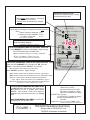
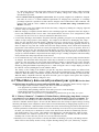
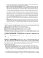
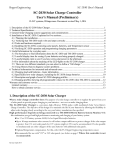
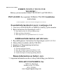
2. Basic instructions for Operating Level L1: Refer to figure 1 which covers basic
operation. It also has references for further information. Note that “% full” will display only 3
dashes until system is fully charged for the first time.
2.1 More details on the five less used display items (which you may not need to know):
AH This is the measure of Amp hours from a full battery. See section 6.2: How the TriMetric keeps track of
battery % full for a description of how this is measured. This is just another way to look at the "% full" data. For
this number to be accurate you must set Program numbers P1, P2, P3 as described in separate instructions:
“Installer’s Instructions for TriMetric TM-2030.” If you use this meter at Level L3 then also P10 and P14 must be
correct.
Continued page 4
2
IMPORTANT DISPLAY NOTE:
Flashing decimal point means “multiply
the number seen by 1000”
CHARGING LIGHT:
When lighted shows “battery 1 is charging”
(“amps” or “watts” is positive)
Flashing lamp means battery is charged.
TM 2030-RV
BATTERY REMINDERS: (optional)
Lamp flashes and display occasionally shows these letters
when:
battery should be recharged “Ch.F”
or “battery should be equalized” “Ch.E”
or “battery voltage low”
“b.LO”
Bogart Engineering
when flashing-meets "CHARGED" criteria
CHARGING
=TIME TO CHARGE
BATTERY
REMINDERS
=TIME TO EQUALIZE
=BATT. VOLTS LOW
See section 2.2 for details
DO YOU PREFER “AMPS” OR “WATTS” to
show in primary display?
See Table 2, Program P4, to change
B1
TO ACCESS PRIMARY (MOST OFTEN USED) DISPLAYS
Push “SELECT” quickly to make display toggle through:
VOLTS (first battery B2, then battery B1)
AMPS
VOLTS
% FULL
B2
SELECT
AMPS (or WATTS) entering(+) or leaving(-) battery B1
Hold SELECT 3
seconds to view
%FULL (for battery 1) Battery B1 must be
RESET
charged fully at least once before this will display.
AMP-HOURS FROM "FULL"............RESET: to 0 Amp-hours
DAYS SINCE "CHARGED"................RESET: to 0 days
TO ACCESS SECONDARY (LESS OFTEN USED) DISPLAYS
Push and hold “SELECT” for 3 seconds until "AH" pops into
display. Immediately release "SELECT". You will see:
DAYS SINCE EQUALIZED................RESET: to 0 days
=AMPS
or
=WATTS
REPLACED PERCENTAGE FROM LAST DISCHARGE
Operating and programming instructions at
www.bogartengineering.com/ins
AH = Amp-hours discharged from a full battery.
Push "SELECT" quickly to toggle through:
dSC= Number of days since the batteries have been fully charged
dSE= Number of days since the batteries have been equalized (if used)
AP or Pr = Shows amps or watts entering/leaving the batteries
Amps : “AP” or Watts: “Pr” (Which one? see P4 table 2, page 7.)
rPC Shows how much energy you’ve replaced of the last discharge
See Section 2.1 for more details on these 5 items.
TO ACCESS PROGRAM OR HISTORY DATA:
Hold SELECT down and watch for “P1” (Program) or
“H1.1”(History) at left in display, then release
SELECT. See sections 5 and 6.4 for details on
program data. See sections 4 and 6.3 on history
data.
NOT SURE WHERE YOU ARE? Push SELECT
repeatedly until you get back home.
The RESET button will reset any of the following:
“Batt% full” (to 100%)
Amp Hours from full (to 0 Ahr)
Days since charged (to 0 days)
Days since equalized (to 0 days)
To RESET any of these:
(1) Use SELECT to view it on display.
(2) Push and hold RESET for 5
seconds.
Except when viewing rPC: hold down RESET to view
“previous discharge minimum Amp-hours".
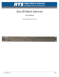
FIGURE 1
TM-2030 Operation Summary
Shows view of TM-2030-RV, but
TM-2030-A operation is identical.
3
dSC Shows the number of days since the battery has been fully charged. This display gradually increases by
1.00 every day until the battery is charged, at which time this value is automatically reset to 0.00. To understand
precisely what the TriMetric considers “charged”, refer to section 6.2: How the TriMetric keeps track of
Battery%Full. For this number to be correct, Program values P1, P2 and P3 must be correct as described in
“Installer’s Instructions for TriMetric TM-2030.”
dSE Days since the battery was equalized. “Equalization” refers to occasionally overcharging a battery to help it
maintain its capacity. It is usually recommended only for liquid electrolyte lead acid batteries, not AGM or Gel
types. This display is intended to remind you when to equalize your batteries if this is not done automatically by
your charging system. It is essentially just a manual timer, that reads in DAYS, so that you can see how long it
has been since your batteries were equalized. Each day when not reset will advance by 1.00 day. Then it must
be MANUALLY RESET by you when you take action to equalize the batteries. For how to reset this, refer to
Figure 1, in reference to the RESET button.
A or Pr (A shows Amps, Pr shows Watts) This display shows either AMPS or WATTS, depending on what has
been programmed in P4 (see table 2 on page 6). If the primary display shows AMPS then this one will show
WATTS. And vice versa
rPC: "Replaced Percentage of recently discharged energy. (Not the same as % full, above.) This shows the
percentage of charge that is being replaced--compared to the amount that was recently removed during the last
discharge cycle. While discharging this display shows 0. When charging it increases--when it shows 100% it has
replaced the same amp hours that was last removed. To preserve capacity of liquid lead acid batteries it is often
recommended to overcharge to 110-120% before going into "float". For AGM batteries to 103-108%.
While showing “rPC”: hold the RESET button down to view how many amp hours were removed during the
last discharge cycle. This is the “base” on which rPC is calculated. The reason for showin this is that if batteries
were only slightly discharged, then a large percentage showing as rPC could be insignificant. (TM2030 Version
2.2 or higher)
2.2 What are Battery Reminders?
This is an optional feature that is designed to help you keep your
batteries maintained, which can remind you to periodically charge your batteries to maximize their life. It comes from
the factory turned OFF. More detailed information about the need for proper charging can be found in section 7 of
these instructions: Important information on how to keep from killing your batteries.
At basic Operating level L1, there are two reminders which you can invoke if you wish:
2.2.1 “Ch.F” (Charge Full) Reminder to charge batteries fully if they haven’t been charged in several days. You
can choose how many days. Lead acid batteries need to be frequently fully charged, otherwise they will lose
capacity. We recommend no longer than about 5 days. (See program P5, table 2). If you set it for 5 days then if
5 days pass without fully charging the batteries the message “Ch.F” will occasionally blink in the display, until
batteries are again fully charged.
2.2.2. “Ch.E” (Charge Equalize) See the end of Section 7 for a discussion of equalization. This display will blink
“Ch.E” as a reminder to equalize batteries, (typically monthly) should you choose to use it. Set the display
interval in days, or turn this feature off by using program P6, see table 2. After you accomplish equalization you
must manually reset the “Days since equalized” number to zero to stop the blinking. First: access the “dSE”
display as described in figure 1. Then use the RESET button. After the equalization period elapses it will blink
again
This function is also used to start equalization with SC-2030 charger. See SC-2030 User’s instructions.)
To activate audible alarm, see P9 and P13 on page 12 (after reading section 5)
2.3 Who might want to use operational level L2, L3 or L4? (See section 3)
2.2.3
Level 2 will allow observing the History data (always being recorded)—see page 5
Level 3 will allow these additional functions:
●Allows addition of the optional Bogart Engineering SC-2030 30 Amp solar charger for your batteries.
●Allows setting up the audible and visual “low battery” alarm. (Table 3, P9 and P13)
●Using a 100A/100mV shunt instead of the more usual 500A/50mV shunt (see Table 3, P11)
●Allow disabling the “automatic reset” when the batteries are charged. (see Table 3, P12)
●Choice of “efficiency factor” different from the default 94% (see Table 3, P10 and Section 6.2)
●Calibrate the battery voltage (see Table 3, P18)
●Allows observation of “filtered” values of volts and amps, used for determining when batteries are
“charged”. (See section 3 and section 6.2, step5, “Level L3 and L4”)
4
3. Beyond beginners: Instructions for Operating levels L2, L3, L4. To
change: see Table 2, program P7.
Level L2 has all the functions of L1, but also allows access to some history information (see below) intended to help technicians
in analyzing systems to see that they are operating properly. Section 4 has a brief description. Section 6.3 has more details.
Level L3 and L4 have all functions of L2, and also adds additional programming functions summarized in Table 3 and detailed
in section 2.3 and 6.4. Also, Level L3 and L4 allow you to observe the “filtered values” of “Volts B1” or “Amps” (which are
extremely sluggish versions of these items) by pushing and holding the RESET button while viewing “VoltsB1” or
“Amps”. The meaning of the filtered values is described in section 6.2, step 5.
The difference between L3 and L4 is that the L4 level raises the requirement for a "charged" battery--beyond the usual
volts/amps requirement.(see Section 6.2 of these instructions). The additional requirement is that the battery must meet the
"float" requirement. defined for the SC-2030 charger described in “SC-2030 Solar Charge Controller User’s Manual”, section
6.5 Primarily useful with the SC-2030 charger. Not recommended unless you understand the “float” requirement.
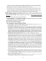
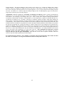
4. History data available with the TM-2030. Table 1 below summarizes the 36 items of
history data. It is available at Operating Levels L2 , L3 or L4. It is being recorded at level 1, but is only accessible at L2 or higher.
These are useful for a technician to determine if your system is working properly, or to diagnose a battery system problem.
To view the History data: Go to page 16 (last page of these instructions) which describes how to access this data. A chart is
provided there for recording the data.
To understand what this History data can tell you about your system: See section 6.3 on page 9.
The items H2 through H6 refer to data during the last 5 battery “charge/discharge” cycles.*
The items H7 through H9 refer to data during the last 5 days.
Display
Identifier
No. of
items
H1
1
H2.1-2.5
H3.1-3.5
H4.1-4.5
5
5
5
H5.1-5.5
H6.1-6.5
H7.1-7.5
H8.1-8.5
5
5
5
5
H9.1-9.5
5
Summary History Description
(See section 6.3 for more detailed explanation)
Cumulative lifetime battery (discharging) amp hours. Analogous to a car odometer, this
display shows how much wear has occurred on your batteries due to the repeated cycling of
your battery system. Every time you remove energy from your batteries this display
records the amp hours you are taking out, but it does NOT record the charging amp hours
when you charge. In this way it measures the wear caused by the discharging and charging
chemical activity on the battery over its lifetime. RESET to ZERO by pushing and
holding RESET for 4 seconds while displaying this data.
For last 5 charge/discharge cycles*: Hours since the end of each cycle.
For last 5 charge/discharge cycles*: Length of each cycle, hours.
For last 5 charge/discharge cycles*: Charge efficiency measurement: Shows how much
more amp hours to charge compared to last discharge (in percentage) for entire last
discharge/charge cycle.
For last 5 charge/discharge cycles*: Lowest % Full value during each cycle.
For last 5 charge/discharge cycles*: Lowest battery voltage for each cycle.
For last 5 days: Highest battery (B1) voltage attained for each day
For last 5 days: If “highest voltage (H7) was less than “charged voltage setpoint” P1 then
this shows amps value while voltage was highest.
If “highest voltage (H7) exceeded “charged voltage setpoint” P1 then this shows the
lowest amps value during time that voltage was above setpoint.
Purpose: To show how close it got to voltage/amp charged setpoints.
For last 5 days: for each day, shows charge percent that was replaced on that day,
compared to the previous lowest discharge.
TABLE 1. See section 6.3 for more discussion of these
*A charge/discharge cycle refers to the time beginning from a fully charged battery, followed by partial
discharge (to less than 98%), and ending when charging it back up to “charged” again. Data is displayed
only when discharge again goes below 98%.
5
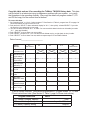
5. Summary of Programming instructions
Program functions applicable for Operating
Level L1 are summarized in Table 2 below. As mentioned above, it is most important that items P1, P2
and P3 (below in Table 1) be correctly programmed for the Battery%Full data to be correct. A step by
step procedure for doing this is described in the “Installer’s Instructions for TriMetric 2030. The additional
functions applicable to level L3 are summarized in Table 3 below. If you need more information than given
in Tables 2 or 3, look at references in section 6.4 of these instructions.
To observe program data follow steps 1 and 2.
To change program data follow additional steps 3 and 4.
(1) HOLD DOWN the SELECT button and watch as the display cycles through several different displays. When
you see P1 in the display, immediately release SELECT. If you don’t release quickly enough, just wait
longer holding down SELECT until you see the P1 again, then release. Then the “Charged” setpoint
voltage (first item shown in table below) will alternate with “P1”, so you can observe its value.
(2) Push SELECT repeatedly to observe programmable data P2, P3, etc, as shown in the left two columns
below. After going through all of these it will go back to observing normal display data. (Volts, Amps, etc.)
(3) If during step 2 you see programmable data that you wish to CHANGE, push both SELECT and RESET
briefly, but firmly at the same time. Three green lamps will flash to indicate that you can now change the
data. Successive pushes to RESET will increase the numbers slowly. Hold RESET down longer to speed up
the change—this will cause data to cycle more quickly through all the possibilities. To make values go
down, you will need to keep increasing until it finally jumps to its lowest value again.
(4) When satisfied with the programmable data, push SELECT to get back into OBSERVE mode. Now either
continue programming as described in step 2, or to get back to regular displays, push SELECT repeatedly.
PROGRAM PROGRAMMABLE DATA
MODE
and ADJUSTMENT RANGE
NUMBER
*Used by
SC-2030
charger
Factory
value
Your
value
*P1
"Charged" setpoint voltage.
10.0 to 65.0 volts
14.3
*P2
"Charged" setpoint amps multiplier, in %
0.1 to 10 percent of the value of “battery
capacity,” P3. If P2 value is 02.0, and P3=400,
setpoint amps=2% of 400 =8 amps.
"Battery capacity" amp-hours
10 to 10,000 amp hours. Note: flashing decimal
02.0
*P3
WHAT IT IS FOR (SUMMARY)
For more information, see Section 6.4
The TriMetric determines that battery is charged when
actual volts is greater than setpoint voltage, and amps is
less than setpoint amps. When this is true the “charging”
lamp flashes to indicate a full battery. This resets “amp
hours from full” to 0 and “battery % full” to 100%, and the
“Days since charged” to 0 Details see section 6.2
220
Enter the battery capacity in amp hours. This setting
influences only the “Battery % full” display numbers and
uses this information to display this % value correctly for
your batteries. Also see section 6.2
point means “multiply number by 1000”; so 1.02
means 1020 amp hours
P4
WATTS or AMPS choice
Pr= WATTS (“Power”), A=Amps
A
Chooses whether AMPS or WATTS shows up on the
Primary display, just after “B1 volts”. If you choose
AMPS, then WATTS shows on the secondary display. And
vice versa.
P5
Days before "time to recharge" reminder
1-100 days, or OFF
OFF
When "Days since charged" equals or exceeds this number,
the "time to recharge"(Ch.F) reminder will flash
periodically in display. See section 2.2
P6
Days before "time to equalize" reminder.
1-100 days, or OFF.
OFF
When "Days since equalized" exceeds this, the "time to
equalize” (Ch.E) reminder will display. See section 2.2
P7
Chooses Operational level; Choose L1, L2,L3
or L4.
L1
L1 is simplest level. L2=next level: shows historical data
L3 Shows all of L1 and L2 plus additional programming
options. See section 3 for meaning of L4
TABLE 2. Program modes for Operating level “L1” (simplest)
6
PROGRAM PROGRAMMABLE DATA
MODE
and ADJUSTMENT RANGE
NUMBER
*Used by
Factory
(and L1,L2)
value.
WHAT IT IS FOR (SUMMARY)
Where to find more information.
write your
value here
SC-2030
charger
*P8
Max Allowed Charger Voltage 10.0-65.0V
P9
Low Battery Audible Alarm Setpoint
0ff or 1-100 percent
OFF
Used only by SC-2030 charger See SC-2030 instructions
When not OFF, audible alarm will sound and “battery
reminder” (bLO) will flash when “% full” is less than this
value, or if battery “volts” less than P13 setting.
P10
Assumed efficiency factor
60 to 100 percent
94
When meter calculates amp hours: Discharging always
decreases amp-hrs at 100% rate. When charging increases
amp hours at this specified percent rate. Also see section
6.2 step 4.
P11
Shunt type:
Sh.H = 500A/50mV shunt
Sh.L = 100A/100mV shunt
Sh.H
Shunt type for correct Amps and amp hour values. Also
see section 6.4, P11
P12
Automatic reset
ON
OFF
ON
When “ON”, Batt % full reset to 100, and Amp-hrs reset
to 0 when Charge criteria are met: P1, P2. Also see
section 6.2 Step 3, and section 6.4, P12.
P13
Battery low volts alarm:
10.0-65.0 volts
10.0
When volts is at or lower than this value, “b.LO” flashes
occasionally in display as “battery reminder.” Also
audible alarm occurs when P9 is not “OFF”. Also see
section 2.2.3 and section 6.4, P13. .
*P14
For SC-2030 Charger: sets maximum time
allowed to be in “absorb” before “float”
0.0 – 25.0 hours
0.0
For exact description, see charging profile graphs, near
page 14 of SC-2030 Solar Charge Controller User’s
Manual. . See section 6.2 step 4 and section 6.4, P14.
*P15
For SC-2030 charger: Max. voltage allowed
during." finish charge" stage.
10.0-65.0 volts
Used only
instructions
*P16
For SC-2030 charger: Float voltage
10.0-65.0 volts
Used only by SC-2030 charger See SC-2030 instructions
P17
Time before daily maximum measurement
will be recorded.
0-23 hours
(N/A)
For history data: H7, H8 and H9 (only): Adjust this to
number of hours after present time that daily measurement
should be recorded. (Usually to occur late at night). Also
see section 6.4, P17.
P18
Voltage calibrate. Set to correct batt voltage
(N/A)
This allows slight adjustment of battery voltage. Use
accurate digital voltmeter and adjust to that value. HOLD
RESET to INCREASE. Push RESET repeatedly to
DECREASE. Also see section 6.4, P18
P19
Program all factory values
Sets all values shown as “Factory values” in this table.
Hold RESET for about 4 seconds to accomplish. Also see
section 6.4, P19
*P20
Percent overcharge before float. 0-20 %
Used only by SC-2030 charger See SC-2030 instructions
*P21
Percent of P3 to which "amps" is limited
during "finish charge". 0-10%
Used only by SC-2030 charger See SC-2030 instructions
*P22
One button auto entry of eight most
important program data. Profiles: 1-31
Allows quick entry of all or most program data, especially
when used with SC-2030 charge controller
by
SC-2030
charger.
See
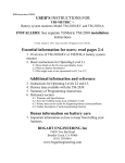
TABLE 3. Additional program modes for Operating Level “L3 and L4”
7
SC-2030
6. Reference section: more technical information:
●warranty and specifications
●How TriMetric keeps track of battery % full ●Using History data ●Programming function
descriptions
6.1 TM-2030 Warranty and Specifications
Warranty: 4 years provided there are no obvious signs of abuse: We will repair or replace (at our
option) to operate at a level specified or implied by our instructions.
Main battery (B1): Measures Volts, Amps, Watts, Battery % Full, Amp-hours from full, Days since charged, Timer
for days since Equalized. Also data logging (history data) described below.
Secondary Battery (B2) sharing common negative with main battery: Measures volts only
Battery Volts: From 10.0 – 65.0 volts for main battery. From 0.0 to 100 volts on secondary battery. Resolution 0.1 volt.
Accuracy ± 0.3%
Amps charging or discharging: With 500A/50mV shunt: 00.0 to ± 999 Amps, resolution 0.1A. With 100A/100mV shunt
0.00-300 Amps, resolution 0.01 Amp. ±1% ± least significant digit.
Note: Maximum amps is often limited by the shunt capability: maximum current for a typical 500A/50mV shunt is
about ±400A. For a 100A/100mV shunt about ±70 Amps. (Depending on shunt design and ambient temperature)
Watts: ±20,000 Watts. (With 500A shunt: when “Amps” read greater than 10.0, Watts accuracy ±1.5% ± least significant
digit.) When “Amps” value is lower, watts accuracy depends on “amps” resolution accuracy.
Amp-hours: Measurement accuracy: 0.00 to ±80,000 Amp-hours to same accuracy as amps.
Battery % Full: Measurement accuracy ±1%. Also measures overcharge. Typical system accuracy, if batteries are
charged full at least every 5 days : typical ±5%. With “efficiency” set to suggested 94% the Battery%Full Display
will be conservative (i.e. display a little lower than actual).
Meter Power requirement: About 30 mA when display is on and about 16mA when display turned off.
Efficiency factor adjustable: 60-100%
Battery capacity settable 10 to 10,000 Amp-hrs.
Serial Data: 5V output stream with all TriMetric real time data ASCII coded.
Charge criteria defined by: Filtered voltage above Vset. Filtered amps less than Iset. Time greater than Tset, all three
adjustable. (Filtered time constant: 140 seconds). See Section 6.2 for detailed description.
Power Requirement: Power from main battery B1: 9-65V, 32mA with display lighted. 16 mA with display off.
Size: TM-2030-RV: Box is 4-1/4 high x 3 x 1-3/8 inch depth with 1/2 in. mounting tabs top and bottom. (10.8 x 7.6 x 3.5 cm.)
TM-2030-A: 4-1/2 x 4-3/4 panel with circuit board 1-1/8 (max) in. deep. (11.4 x 12.1 x 2.85 cm.)
History data: retained in memory when power turned off
●Cumulative amps discharged during battery lifetime (0-999,000 amp hours) to measure battery wear
for last 5 charge/discharge cycles the following are recorded:
●Hours ago since end of cycle
●Length of cycle (hours)
●Amp hour efficiency factor for each complete cycle (to show charge efficiency of battery system)
●Minimum voltage for each cycle.
●Minimum battery %Full for each cycle
For the last 5 days:
●Maximum voltage each day
●Amps value: intended to show how close to “charged” the battery system got
When maximum voltage greater than charged setpoint volts: shows minimum amps.
When maximum voltage less than charged setpoint volts: shows amps at maximum voltage
●Maximum value percent charge returned compared to most recent discharge
6.2 How the TriMetric keeps track of battery % full. The TriMetric
uses “Capacity (P3)”, “charged setpoint volts (P1) , “charged setpoint amps percentage” (P2)
and “efficiency factor” (P10).
Initially when the TriMetric is first turned on it does not have any way of knowing how full the battery is. The
“battery % full” display will start out blank : “---” Here are the steps it uses to determine the % full
1.First the battery must be initially charged fully. When the TriMetric is charging, there are two choices you can
select for what defines “full charge”:
A: More common choice, if program P7 is in level L1, L2, L3: Two conditions must be met simultaneously:
(1) while charging, the battery voltage must exceed the “Charged setpoint voltage” (which you set by Program
8
P1.) and (2) the charge current (amps) must decline to below the “Charged setpoint amps” (which percentage
you set by Program P2). Note that filtered versions of “Battery voltage” and “battery amps” are used,
described in step 5, below.
B: Less common choice if program P7 is in level L4: This is typically a higher level standard for “charged”
than when in Levels 1-3. It allows additional requirements for charging time, and degree of overcharge
percentage required. It is possible to use this to define “charged” with or without the SC-2030 connected. The
batteries must reach the “float” condition as described in the “SC-2030 Solar Charge Controller User’s
Manual” section 6.5.
2. When the above occurs, the TriMetric then declares the battery “charged” by flashing the “charging” light and
resets the “Days since charged” to 0.
3.When the charging is completed, and the batteries start to discharge again the “Amp hours from full” display is
reset to 0.00, and Battery%Full is reset to 100%. This assumes that the “auto reset” is on—(Program P12), which
is always the case in Level L1 or L2. It may be turned off if desired in Level L3
4. As the battery discharges, the TriMetric “amp hours from full” gradually go negative at a rate depending on the
number of amps, and go positive when charging. For example if the batteries are discharging with “amps” =
minus 10.0, the "amp-hours from full" display gradually decreases by exactly 10.0 for every hour that goes by.
Similarly, when amps are positive 10 amps (charging) the "amp-hours from full" display gradually increases by
almost 10 amps for every hour. The "almost" has to do with "charge efficiency factor" which can be adjusted by
program P10. If the efficiency factor is set to 100%, the amp-hours will go up by exactly 10 per hour , however if
the efficiency factor is 94%, the "amp-hours from full" display goes up by only 94% of 10, or 9.4 amp-hours for
every hour. The purpose of this is to account for the fact that you don't get as many amp-hours out of the battery as
you put in, so that the TriMetric "amp-hours from full" display will give a reading of amp-hours which reasonably
closely estimates how many amp hours have been removed.
5. It was mentioned in step 1 above that filtered values of “volts” and “amps” are used to judge when the batteries
are charged. This means that before using these values they are filtered so as to be only very slowly responsive
versions of “volts” and “amps” are used, so that quick variations of voltage or current don’t give a false “charged”
signal. (They are filtered with a time constant of about 2.4 minutes.) These “filtered” versions can be viewed, if
desired, by putting the TriMetric in Operating Level L3—when viewing the “volts” or “amps” display you will see
the “filtered” version by holding down on the “RESET” button.
The “battery % full” reading of the TriMetric just puts the “amp hours from full” number in a different form,
which depends on the “amp hours “Capacity” number that has been programmed in to the TriMetric in program
number P3. When the battery is full and the “amp hours from full” value is 0 then the Battery% full will be 100.
When the battery is depleted so that the “amp hours from full” goes to a negative value equal to the “capacity”
programmed in P3 then the Battery% full goes to zero.
6.3 What History data can tell you about your system See the chart
on the last page to see how to access and record this data. As explained in detail at the top of page 16:
There are 9 types of data recorded as “History” data. These are labeled H1 through H9.
1. Use program P7 to put meter in complexity level 2, 3 or 4.
1. Get to history data by holding “SELECT” down until you see H1.1 come into display.
2. Push SELECT button to advance to each of 9 types of data
3. For each data item, (except for item 1.1) push RESET to go back in time, up to 5 days, or 5 cycles.
`H1.1: “Battery Odometer”: Cumulative Lifetime Battery (discharging) Amp hours: Analogous
to an odometer in a car: Displays how many amp-hours you got from the battery system over its lifetime. This
number starts at 0 when manually reset which would usually be at the time of initial installation of the batteries. See
reference to “RESET” button in figure 1 for how to do this. Whenever the value of amps is negative (charge is leaving
the battery) the display counts "amp-hours" down. It does not record when battery is charging (amps is positive). It is
analogous to a car odometer—rather than miles travelled it shows how much total energy the batteries have delivered.
Evaluate performance of the batteries and the level of care which they received. In case of power interruption to
the meter you will only lose a maximum of 3 hours of this data--because this data is automatically stored to
non volatile memory every 3 hours. This number can be displayed to -999,000 amp hours, which is longer
than most battery sets would be expected to last. If it approaches this, you should record the value and
manually reset it--since it does not just roll over to zero by itself after 999,999.)
Often battery life of "deep cycle" batteries is rated by the number of discharge cycles they will undergo without
failure--however this usually assumes a fairly complete discharge during each cycle, followed by complete
9
recharge. The life of deep cycle batteries is increased if the discharge depth is less--in fact the number of
cycles of life is inversely related to the depth of discharge of each cycle--so if you discharge only half the
amount during each "cycle" the battery typically will last about twice as many cycles.
When buying batteries you have a choice whether to double the number of batteries in your battery set—which
will reduce the average cycle depth of discharge to one-half, which should approximately double their number
of cycles. If the number of cycles did actually double there would be no cost benefit since twice the battery size
would cost twice as much to replace. (Of course you’d get more days of autonomy.) But in a vehicle it would
add extra weight. This measurement is a way of getting quantitative data on these kinds of questions.
H2-H6: Battery Charge Cycle Data provide answers to these system questions for the
last five charge/discharge cycles: A discharge/charge cycle begins at the time the battery is “fully charged”
and ends at the next “full charge”—a precise definition is given in section 6.2: How the TriMetric keeps track of
battery % full.
H2 and H3: Did too many days go between full charges?
H4: System efficiency: Is a reasonable percent of the total charging energy being recovered during
each discharge(80-97%)—not too much or too little?
H5: How deeply are the batteries being discharged?
H6: How low does the battery voltage go?
More detail about what H2-H6 can tell you:
H2.1 through H2.5: (somewhat redundant information to H3) How many hours ago that the cycle in
question ended (H2.1 most recent cycle. H2.5 oldest cycle data).
H3.1 through H3.5: Length of the cycle in question, in hours. This shows how much time goes by between full
battery charges. Frequent charging helps keep them from permanently losing capacity. If solar charging is
used, and the days are sunny, they should charge nearly every day. If times are too long, say over 4 or 5 days
(96-120 hours) in a system that is being significantly discharged every day batteries may not being charged
sufficiently to maintain their capacity—although this could be OK if they are hardly used and mainly on float.
Long times could also mean either that the charger “absorb voltage” or “absorb time” is set wrong, or
that the “charged” setpoints in the TM-2030 programs P1 and P2 may be set incorrectly so that the
charging system cannot reasonably reach them. Then refer to data in H7-H9 (below) to show why.
H4.1 through H4.5: Total charge efficiency over each cycle (records total discharge divided by total charge)
which shows how efficiently the batteries are storing energy for that cycle—which from a theoretical system
efficiency standpoint would be ideal if 100%--but for a real system will be less. If this number is
consistently over 100% that means that the wiring to the shunt is incorrect, (batteries cannot be more than
100% efficient!)—possibly a charging source (possibly solar controller, or chassis ground?) connected to the
negative post of the battery instead of on the load side of the shunt, so the meter is not measuring it. If
unreasonably low, say below 70%, that may also indicate a miswiring—in this case a load that is connected
to the negative post of the battery. Or perhaps the batteries are old and inefficient. Or the charger could be
overcharging the batteries (which could also be damaging batteries—but this may not be significant if batteries
have been recently very lightly used—see “rPC” in section 2.1 page 4). For liquid electrolyte batteries an
average number between 80 and 90 is reasonable. If a higher average, the batteries are getting less than
10% overcharge, which is usually less than optimal for liquid electrolyte batteries. For AGM batteries ideal
could be 92-96% as they do not need as much overcharge. Another cause of an occasional high
percentage is that the temperature has gone down significantly between one full charge and the next. This can
cause the “charge setpoints” to be achieved with a lower state of charge than before—so less energy was able
to be charged. Similarly, an occasional low percentage could result if the temperature has risen at the
batteries, because when warmer they can accept more charge than before when cooler, which will reduce the
apparent efficiency value.
There should be some consistency in the readings. Although the values should ordinarily be less than 100%, as
said they can occasionally be greater than 100% when the temperature of your batteries drops as explained
above. If readings are wildly inconsistent it could be a wiring error, with a source or load that is connected to
the negative side of the battery, (a frequent installer mistake!) instead of on the load side of the shunt. (See
Figure 1 of TM2030 Installation instruction.)
H5.1-through H5.5: Minimum Battery % full during each cycle. This is another check to see how much
usage the batteries are getting, that they are not being run too low between charges.
10
H6.1 through H6.5: Minimum voltage during each cycle. This can show if the battery voltage is too low
before being recharged. Going below 11.5V or so (12V system) would indicate batteries are nearing their low
limit.
H7, H8, H9 check if proper charging is taking place.
Charging data for each of the last 5
days: H7:Maximum charging volts. H8:Minimum charging Amps. H9:Maximum overcharge percentage
●Each recorded data represents a 24 hour period that ends at a time of day (or night) that you can determine by
referring to Program 17, on page 13
Purpose of H7, H8 data: The way that the TriMetric determines that the batteries are “charged” (in Level 1, 2 and 3
operation) is to sense that the battery volts exceeded the programmed P1 value, and the charging Amps are less
than the value of P2 times P3 (P2 is expressed as a percentage). The H7 and H8 history data track these values
so you can see, during each 24 hour period, how high the volts actually got, and how low the Amps got—so if
these values were not achieved you can understand why.
The H7 data shows the maximum voltage the batteries were charged on that day. The H8 data shows the
minimum amps that were attained when the voltage was near that maximum (Filtered values of volts and
amps are recorded, as defined in section 6.2.5.) The meter (in Level 1, 2 or 3) will only indicate “charged” on
days when the H7 maximum volts data is equal or greater than the P1 program data—and the H8
“minimum amps” data is less than the product of P2(percent) times P3, so the H7, H8 data allow you to
discover how close these values got, on each of the last 5 days.
Purpose of H9 data: When the meter is in “Level 4” operation, in addition to the above, to sense “charged” it also
requires that the returned percentage of charge exceeds the P20 value. That is what the H9 History data tracks.
Also use the H7 maximum daily voltage data to:
verify that the charge controller or chargers are charging to correct absorb voltage.
verify that sufficient charging is taken place during that day to reach the “absorb” voltage.
Also use the H8 maximum daily voltage data to:
verify that enough charging time occurred to reduce the amps to a satisfactory low value.
Also use H9 to see how much daily overcharge in percent was achieved
verify that sufficient overcharge took place that day (compared with the most recent low charge point) has been
during the day. According to many battery experts, properly charged liquid electrolyte lead acid batteries
should be charged with 110-120% more than the (low) level to which were just previously discharged to ensure
they will not gradually lose capacity. AGM batteries should be charged to 104-109% of previous discharge.
●Technical note: The value recorded for the H8 minimum current data depends on whether the voltage on that day exceeded
the “charged voltage” setpoint programmed in program P1.
If the H7 (maximum filtered voltage) on a particular day is less than the “charged voltage” setpoint :
Then the amps value (for that day) is the (filtered) amps value at the moment that the maximum voltage
occurred.
If the H7 (maximum filtered voltage) on a particular day is greater than the “charged voltage: setpoint:
Then the amps value is the minimum (filtered) amps during the time that the volts exceeded the setpoint
6.4 Further description of each programming function.
Instructions for
observing and changing programming items is in section 5
P1 and P2: "Charged" setpoint voltage and "charged" setpoint amps.
Purpose of data: The "charged" voltage (P1) and amp (P2) setpoints provide information the TriMetric uses to
determine when your battery set is "charged". Details are given in section 6.2. The amp setpoint (P2) is now
entered as a percentage of P3, unlike with the TM2020 or TM2025, when the amps were entered directly. So
the actual amps value, below which the batteries need to be charged, is the percentage in P2 times the capacity P3.
About voltage and current "charged" setpoints: Of these two setpoints, the “voltage” setpoint is the most critical,
and the “current” setpoint less so. If you have only low current charging sources you could set the current setpoint to
“OFF”—however both should be used if at least one of your chargers is a high current charging source such as a
generator charger or inverter/charger. More specifics follow.
Choosing “charged setpoint volts”: Section C1 of the “Installers instructions for TriMetric TM2030” has simpler
instructions on determining these parameters. Similar information is given in section 7 of these instructions.
Some technical details: For a 12 V lead acid battery system, the voltage setpoint will usually be between 14.0 and 14.8 volts. Double these
numbers for 24V systems or multiply by 4 for 48V systems. As pointed out in Section 7, your chargers and charge controllers must be set
according to information from the battery manufacturer. Once those are set, the TriMetric voltage setpoint should be 1% or so lower than
the charger settings. If this is done the TriMetric "charging" lamp will begin to flash (as indicated on the top “charging” lamp on the
panel) some time before the charging system decides that the batteries are charged and stops charging your batteries. If you have two or
11
more chargers, such as solar and generator, both chargers would normally be set to charge to the same voltage, and the TriMetric should be
set with the voltage low enough for either one to reach when the batteries approach full charge.
Choosing the “charged setpoint percentage amps”: IMPORTANT: New for the TM-2030: enter this percentage directly into
program P2 from 1.0 to 10.0%. The method of setting this has been changed from the older TM-2020 or TM-2025. If you have a
generator or other charger that has high charging current capability it becomes important to also set the “charged setpoint amps” in the
TriMetric. This is because a high current charging source can force the battery voltage to rise and meet the “charged voltage” setpoint even
though the batteries are not yet well charged. With such a charger, once the voltage reaches its maximum “bulk voltage” the charging
current (amps) will start out high, then gradually reduce as the batteries become more charged. Proper adjustment of the “current setpoint”
will ensure that the TriMetric will not consider the batteries “charged” until the charging current goes below the setpoint amps. The lower
you set this value, the more “charged” the battery must be before the TriMetric will declare the battery to be “charged”. To set this value
you must know the amp-hour capacity of your battery system which has been set in program P3. We often suggest value for the “current
setpoint” setting that is 2% of C, which is the default setting when the meter is new, where C=battery system capacity in amp-hours that is
programmed in P3. For example if you put =700 amp hours into P3, then a P2 amps setting of 2% would be 2% of 700 = 14 amps. Better
charging would result using 1% of C or even 0.5%, for the battery to be really charged—however this may require more solar time (for
example) than is usually available. If you are in complexity levels L1, L2 or L3, when you enter the current setpoint the TriMetric will
require that simultaneously both the filtered voltage setpoint be equal or exceeded, and the filtered current (amps) value be less than or
equal to the current setpoint before the TriMetric will indicate that the batteries are “charged”. In level L4, further requirements need
be met, as described in the SC-2030 Solar Charger manual. The “filtered” values are very sluggish versions of these parameters—
explained in Section 6.2 step 5. Also, if you are set to complexity level 3 or 4 (using Program P7) you can observe these filtered values of
amps and volts. To do so, when observing either amps or volts, when you hold the reset key down the filtered value will show in the
display.
Usually in float mode? Another possibility we should address is if your charging system stays much of the time in "float" mode, which may
be true for a “line tied” system, or a battery system in an RV that is only occasionally used, with its battery usually connected to a charger
that maintains it at “float” voltage . With a lead-acid liquid electrolyte battery the "float" voltage may be 13.4 volts (for 12V system) For a
system that is usually in “float” mode, the TriMetric voltage setting can be just below 13.4, (or whatever the float voltage is) and the
"amps" setting can be for some low value, such as C90 or so, or to a value which the "amps" would only go below during the "float"
condition. Then the TriMetric will reset only after the "float" condition is attained.
P3: Battery assumed capacity. This is the basis for calculating the Battery % full number. The Battery % Full is
calculated as = (Capacity – AmpHoursFromFull) ÷ (Capacity), expressed as a percentage. The Capacity (in amp hours) is
what you program in here. The AmpHoursFromFull is the value shown on the secondary display group. Also see the
“Installer’s instructions for TriMetric TM-2030” section C, under program item P3.
P4: Watt/Amps choice. Select which you prefer as your primary choice. Explained on Table 2.
P5: Days before “time to recharge” Battery reminder. Explained in section 2.2.1 and Table 2.
P6: Days before “time to equalize” Battery reminder. Explained in section 2.2.2 and Table 2.
P7: Operating Levels This allows switching to any of four Operating levels: L1=simplest, and OK for most users. L2= All
of L1 plus allows viewing History Data information. L3 and L4: All of L2 plus many additional programming options
shown below. L4 also redefines “charged” criteria. See section 3.
The following program items are available when the TM-2030 is switched to L3 or
L4 level. Use program P7 to select L3 or L4
Program modes P8, P14, P15, P16, P20, P21 and P22 are only used only with the optional SC2030 charge controller. See SC-2030 Solar Charger User’s Manual: Section 6.4 and profile graphs for exact
descriptions.
P9 and P13: Audible Alarm. How to turn on or off.
First be sure to program P7 (above) to “L3” (or
“L4”). Activate audible alarm by programming P9 so it is NOT ‘OFF” but has a number. Adjust the number for
“Percent full” below which you want the alarm to sound. We suggest 50 to start. Then go to program P13 and program a
battery voltage below which it will sound. (Suggest 11.4 for a 12V system—22.8 for 24V.) Then the alarm will sound if
the volts go below 11.5 or the % Full goes below 50%. When the alarm comes on it may be silenced by the reset or select
button--but the alarm's presence will still be indicated by the flashing "BLo" in the display window.
P10 Assumed charge efficiency factor:
Purpose of data: "charge efficiency factor" See section 6.2 step 4 for an explanation of “charge efficiency factor”.
Choosing values of "charge efficiency factor": In the “L1” mode this value is fixed at 94%. If you wish to adjust it to
a different value you will need to switch to “L3” mode. The actual "charge efficiency" factor for lead acid batteries
while they are not at the top of charge is generally higher than 94%, so this will usually give a conservative value for
"amp-hours from full"-- that is the meter will generally slightly under-estimate the “% Full” value for the batteries
which will give a useful practical result for knowing state of charge.
Optional technical note: Some people familiar with batteries will be surprised that the suggested "efficiency factor" is as high as 94%. Without going
into all the details here, there are two reasons for this: (1) The number entered in the TriMetric is not true battery efficiency, or energy efficiency,
(which is often quoted at 70-80% for lead acid batteries) but charge efficiency. Charge efficiency (the ratio of total amp-hours you get out divided
by total amp-hours to charge the battery) is always greater than energy efficiency. (2) What is entered in the TriMetric is not even the overall charge
12
efficiency of the battery, but the charge efficiency while the battery is not at the top of charge, and not gassing. A battery is not charge efficient
while at the top of charge, so if this part is excluded the battery is very charge efficient. (We have measured this to be 95-98% with Trojan wet cell
batteries.) Also note—when batteries are given a good, adequate charge they will not show up with very high efficiency.
P11: Shunt type: This must be set according to the shunt type you have. This determines the sensitivity of the "amp"
input to the TriMetric, so that it reads correctly for the shunt you have. If your "amps" readings appear to be off by a
factor of 10, the most likely cause is this that is not set correctly for your shunt.
Choosing value of "shunt type". At L1 level this is fixed at the more common 500A/50mV shunt. The 500A/50 mV
shunt is specified by “Sh H” (“High current shunt”) If you have a "100A/100 mV" shunt, you should enter Sh L
("Low current shunt"). Only the ratio shown is important to the TriMetric, so that from the TriMetric's point of view a
200A/200 mV or 300A/300 mV shunt is equivalent to a 100A/100mV shunt.
P12: Automatic reset on/off for amp hours described in section 6.2, step 3. It must be on to measure battery percent
full, but it may be turned off if the meter is used in a different application. When off, “amp hours” will never be reset to
zero except by using the manual reset button. The “Percent full” will then not work to provide battery percent full
information.
P13: “Battery Low” setpoint: This allows you to set the level at which the “low voltage battery reminders” will flash. It
also sets the audible low battery alarm as described in section P9 above. Set the value in volts that need to be attained for
the “B.Lo” reminder to light, or audible alarm to sound. Also see P9 and P13 on previous page.
P17: Time of Recording for Daily history data: This shows the number of hours that will elapse before the daily H7, H8
and H9 logged data will be recorded. So if the actual time is 10PM, and you want the day’s data to be recorded at 1AM,
enter “3” hours here.
P18: Voltage calibration: This is the “voltage calibration” adjustment if the voltage shown is not exactly correct. This
calibration is stable, and should not ever be necessary to adjust—but if you find you need or want to—follow these steps.
1. Get a multimeter that you know to be accurate. Carefully remove the TriMetric panel from its box to gain access to
the back of the unit. With the multimeter measure “volts” between the “G1” and “+” terminals that are on the back
of the TriMetric circuit board. While doing this you must be connected to a voltage source that is stable. (At the
factory for best accuracy we use a voltage exactly between two 1/10 volt readings—we use 29.95 volts and follow the
procedure below until we get to “29.9” on the meter.)
2. Switch to the P18 Program, and put it in the “program” mode (3 lights flashing). Observe “correct” value on the
multimeter--then push and hold “RESET” down until voltage on the TriMetric display jumps higher than the
multimeter reading. Release “RESET”. Then successively push “RESET” with many short pushes to gradually bring
the voltage down until it is agrees with your multimeter. At 12.05 volts it takes about eleven pushes to bring it down
by just 1/10 volt. It will go down faster with a higher battery voltage. When correct, push SELECT to finish.
P19: Program factory values. This reinstalls all the default (factory) values in all the program locations at once—so will
erase any data you have put in. Hold down the “RESET” button for several seconds until this occurs.
7. Important information about battery charging to keep from
killing your batteries
Even if you abuse your batteries they will probably work just fine—for awhile. By knowing
how to care for them you can extend their life to maximize their return to you.
1. Charging to correct voltage. Charging for sufficient time. Charging at frequent intervals.
2. Not often letting them become totally discharged, or left very long in a discharged condition.
3. For liquid electrolyte batteries, maintaining the water level always above the internal plates.
The most important thing to maintain your batteries is to charge them to correct voltage and current and “often”. We will
try to define both. The most common “battery crime” for which the penalty is having to replace your batteries too soon, is
charging with insufficient voltage, or not charging long enough to get them fully charged.
Charging voltage: One of the most important numbers to know about your batteries if you wish to maximize their life is
the “Recommended absorption charging voltage” for the batteries. (This is usually given for a battery temperature of 25
degrees C or 77 degrees F.) The typical well designed charger or charge controller used with “deep cycle” batteries (which
are the type of batteries designed to be periodically discharged and charged) starts by charging fairly fast (at a high rate of
amps), but the battery voltage may start out low if the battery is not well charged. Charging causes the battery voltage to
gradually rise over a period of possibly hours—but as soon as it rises to the “absorption charging voltage” the charger is
13
supposed to be smart enough to stop allowing the voltage to rise higher than this to avoid damage to the batteries—although
the charger will continue to send current to the batteries at this voltage while the current (amps) slowly declines. The
manufacturer of the batteries should specify what this voltage should be. Get information on charging parameters
from the manufacturer, or ask the dealer who sold them to you who hopefully should know. Unfortunately many do
NOT know. This voltage will be slightly different for different types of batteries: For example, 12 volt liquid electrolyte
lead acid batteries will have an absorption charging voltage of about 14.4 -15.0 volts. AGM or Gel batteries will have a
lower voltage, perhaps at 13.9-14.4 volts. (Multiply these by 2 or 4 for 24 or 48V systems.) Your charger(s) must then be
set to the battery manufacturer’s (not the charger manufacturer) recommended voltage. If the voltage is too low or too
high, battery life will be impaired. It is especially important to get this correct for the AGM or Gel types—not least because
they are even more expensive than liquid electrolyte types. Ideally you can adjust this voltage on every charger (or charge
controller) you have. Unfortunately some chargers do not leave much choice--and some do not charge to a high enough
voltage, and then you will have to settle for whatever the charger determines, at possible detriment to your batteries. If you
have multiple charging sources, for example if you have a stand alone generator, a charger or converter, and also solar, or
perhaps also your engine alternator, ideally all chargers should be set identically according to what the battery
manufacturer recommends. Often that’s not possible (say, for engine alternator) then the voltage value for that charger
should be lower—however then you should have another charger to back that one up to periodically charge to the proper
absorption voltage if you want to maximize battery life. Although some chargers just have a switch that says “AGM” or
“Liquid electrolyte” to set this voltage, it is useful for you to know this actual voltage number since you now own a
TriMetric, to check that the charger is really charging correctly. If all chargers are not set correctly you may be buying
replacement batteries before you expected.
Battery temperature: If the battery temperature varies considerably the charging source should adjust its voltage to
temperature. A well designed charger will have a temperature sensor, and adjust its voltage a little higher at cold, and
lower at warmer temperatures. As mentioned above, the absorption charging voltage is usually given for a battery at 25° C.
(77° F.)
You can use the TriMetric to determine what your charger is adjusted to by watching “Volts” as the charger is charging the
batteries—and eventually you should find that the voltage does not rise any more as the batteries approach full charge. An
easier way which doesn’t require that you constantly monitor the meter is to use the “History data” (see Section 4, item H7.
and H8.)
Charging for sufficient time: Not only must the voltage be high enough, but it is the nature of battery chemistry requires
the passage of some time at the “absorption voltage” to fully charge. So this means not only adjusting the voltage correctly
as mentioned above, but charging for enough time to get the battery well charged. There are three ways commonly used to
measure this. (1) charge at absorption voltage for a set time, sufficiently long: from 1-8 hours. (2) Better is to retain the
absorption voltage for a long enough time for the charging current (in amps) to drop to a low enough value (sometimes
called the “return” value). This is what the TriMetric measures when it makes a judgment about whether the battery is
charged. A practical value for this value of amps is to take the total “amp hours” capacity of the battery system and divide
by 50 to 200 to get an “amps” value to which the batteries should reduce before charging is completed. We often suggest
capacity ÷50, (2% of capacity) not because it is absolutely ideal, but it is a compromise for getting them charged in a
reasonable amount of time. (3) Often considered the best way is to return a specified additional percentage of amp hours—
for liquid electrolyte batteries returning 110% to 115% of the charge that was just previously discharged is often
recommended--for AGM batteries the number is 104%-108%. Very few chargers use this method, but our SC-2030 solar
charger has this capability (when paired with the TM-2030 monitor.) (4) The “classic”, but rather inconvenient method
which works only for “liquid electrolyte” batteries is to use a hydrometer to measure the specific gravity of the battery acid
of each cell to see that it comes up to a high enough value as specified by battery manufacturer. But if you have liquid
electrolyte batteries this is worth occasionally checking—to be done just after your batteries have been pretty well charged.
Why solar panels can be good for batteries: Even if you don’t get all your energy needs from solar, these are often
a very useful complement to your engine chargers to reduce the amount of engine time required to charge and yet
get a good charge on your batteries. Use your engine charger(s) to begin charging when your batteries are low,
which is when they absorb energy at a higher rate, making more efficient use of your engine. Then once they
approach full charge turn off the engine and let the panels deliver a slower, but much longer charge to get your
batteries well charged without having to run a generator for a long time.
Charging to full sufficiently often: It doesn’t hurt to discharge a “deep discharge” battery to 50% or less—that’s what
they are designed to do—but lead acid batteries should not be left uncharged for a long period. The reason is that if the lead
sulfate reaction product that is produced as the battery is discharged is left too long it changes its form so as to be harder to
convert back to its “charged” state—lead, lead dioxide and sulfuric acid--so you will not be able to retrieve as much energy
14
from the batteries. We suggest charging to “full” at least every five days or so. To help, the TriMetric has a “battery
reminder” function to remind you to charge the batteries fully after a certain number of days have elapsed in which they
have not been brought to full charge(which you set using Program P5). Once you fully charge them the flashing reminder
will cease. See Section 2.2.1. Also, the “days since charged” display on the “secondary displays” page 3 will tell you how
long it has been since they have been fully charged.
"Equalization" refers to a process of occasionally overcharging your batteries--which is usually recommended by
manufacturers of "wet cell" lead acid batteries--but, however is usually not recommended for “AGM” OR GEL sealed lead
acid batteries, and overdoing it can damage these types. More recently some companies making AGM batteries
occasionally recommend this. (Example: Concorde Battery Co.) The Trojan battery company recommends that their wetcell batteries be equalized every 1-2 months. This helps to completely recharge the battery--which helps maintain the
battery capacity. Some charge controllers, or battery chargers have an "equalize" mode which is controlled either manually
or automatically. The SC-2030 now has the capability to do a manual equalization (when controlled by the TM-2030). This
TriMetric function is intended for use primarily for systems that require manual equalization--and reminds you to perform
this after the programmed time. Placing the charger in "equalize" mode involves extra charging after the batteries have
reached the "charged" criteria which allows the voltage to rise extra high for a period of time--for example the Trojan
Battery Co. recommends charging to 15.5 volts (for 12V systems--double this for 24V systems) and keeping the batteries at
that level for 2 hours. Other manufacturers may have different recommendations. It is usually advisable to check water
levels in the batteries after equalization, as it causes some water loss. After equalization has taken place you must
manually reset the "days since equalized" display (by pushing “reset” when the “days since equalized” extra data is
displayed)--this does not take place automatically. This will turn off the "time to equalize" reminder, which will
reactivate only after another equalization period has elapsed.
For “liquid electrolyte” batteries: Every month or so check the water levels in the battery cells to make sure that
the water covers the plates. It is not good for the batteries if the level drops below this level.
15
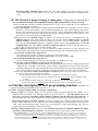
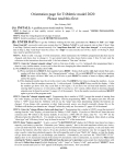
Copy this table and use it for recording the TriMetric TM-2030 History data. This data
can be helpful to a technician trying to diagnose a problem with your system, or to verify
that it appears to be operating normally. Also copy the data from program modes P1, P2
and P3 and copy it to the second chart at bottom:
To access this data:
1. Set “Operating level” to L2 or L3 using program P7. See Section 5, Table 2, program item P7 on page 6 of
these instructions for how to set to L2 or L3.
2. Push and hold “SELECT” down and watch display for “H1.1”, then quickly release SELECT. If you miss
the first time, just repeat until you succeed.
3. You will now observe data at “H1.1” on table. You can record this data in the box on this table just under
“X.1”. (near top left table).
4. Push “SELECT” to move down one row on table.
5. Push “RESET” (except for H1.1) to view and record all data moving to right (back in time) in table.
6. Push “SELECT” to move down one row, and then repeat steps 5 & 6 until table finished.
Date of record______________________
History
Number
X.1
Most Recent
H1.1
H1.1
X.2
X.3
X.4
X.5
Least Recent
5 day Log Info
5 Charge-Discharge cycle info
Cumulative A-hr
H2:Hours since
cycle ended
H2.1
H2.2
H2.3
H2.4
H2.5
H3: Length of
Cycle-hours
H3.1
H3.2
H3.3
H3.4
H3.5
H4: Amp-hour
efficiency %
H4.1
H4.2
H4.3
H4.4
H4.5
H5: Cycle Low
% Full
H5.1
H5.2
H5.3
H5.4
H5.5
H6: Cycle Min.
volts
H6.1
H6.2
H6.3
H6.4
H6.5
H7: Day’s
Maximum Volts
H7.1
H7.2
H7.3
H7.4
H7.5
H8: Day’s
Minimum Amps
H8.1
H8.2
H8.3
H8.4
H8.5
H9: Day’s percent
amp-hr charge
H9.1
H9.2
H9.3
H9.4
H9.5
To aid in system analysis, view values programmed in Program modes P1, P2 and
P3 and record them here: (See Section 5, Table 2, page 6 of these instructions.)
Value
Program mode item
P1: voltage “charged” setpoint
P2: current “charged” setpoint
P3: Battery capacity setting
Volts
Amps: % of P3 value
Amp-Hr