1
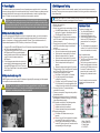
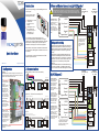
3. Door and Reader Connections: (a) MICROgarde 1
There are 2 main types of
MICROgarde controller:
MICROgarde I is a 1-door
controller with
connections for 1-2
readers.
MICROgarde II is a 2door controller with
connections for up to 4
TDSi readers or 2
non-TDSi readers.
Sensor
Lock
Reader 1
(outside)
Reader 2
(inside)
Exit button
The controllers can operate independently or as
part of a networked system administered from a single
computer (PC) using the supplied MICROgarde or EXgarde
PRO software. In addition, spare inputs and relays are
available for monitoring and control of other equipment.
Copyright © 2012 TDSi
Mounting
The MICROGarde controller is designed to be mounted on flat
surfaces while allowing cables to pass underneath. 3 screws are
required to mount the chassis onto a wall.
2. Communications
Rotary Dial switch
Sets number of unit in network.
See section 5.
All communications and reader cabling runs should be in
shielded (screened) cable and at least 2 metres long for
full EMC protection and maximum reliability. Always ensure
the MICROgarde chassis is connected to a good earth
grounding.
Communication and other peripheral cable should only
be earthed at the MICROgarde chassis unless the item
(e.g. reader, egress, lock etc.) is mounted on an earthed
metal surface. In this case, do not earth the cable at the
MICROgarde unit to avoid earth loops and possible
interference.
Keep all unshielded cable runs and earth/drain wire “pig
tails” as short as possible. To minimize exposed earth
braid, never remove more cable sheathing than necessary.
This diagram shows the
colour-coding used in
TDSi readers. Other
makes of reader may
have different colour
coding.
Lock PSU
(see section 4)
+V 0V
MG PSU
(see section 4)
12V GND
3
5
Comms
11: N/C
12: Com
13: N/O
14: Door Sense
15: 0V
16: Exit Button
Door 11 13.7V Out:10
0V Out :9
+13.7V IN :8
0V IN :7
5v :6
RS485A :5
RS485B :4
0v :3
RS232TX :2
RS232RX :1
RS485 Term
11: N/C Lock
12: Com Strike
13: N/O RL1
14: Door Sense
15: 0V
16: Exit Button
Door 11 13.7V Out:10
0V Out :9
+13.7V IN :8
0V IN :7
5v :6
RS485A :5
RS485B :4
0v :3
RS232TX :2
RS232RX :1
RS485 Term
RS232 socket viewed
from solder side
Comms
Termination switches UP on first unit (closest to PC) ONLY
(b) Serial (PC > 15m from first controller) or USB
Comms
To other controllers
11: N/C
12: Com
13: N/O
14: Door Sense
15: 0V
16: Exit Button
Door 11 13.7V Out:10
0V Out :9
+13.7V IN :8
0V IN :7
5v :6
RS485A :5
RS485B :4
0v :3
RS232TX :2
RS232RX :1
RS485 Term
11: N/C Lock
12: Com Strike
13: N/O RL1
14: Door Sense
15: 0V
16: Exit Button
Door 11 13.7V Out:10
0V Out :9
+13.7V IN :8
0V IN :7
5v :6
RS485A :5
RS485B :4
0v :3
RS232TX :2
RS232RX :1
RS485 Term
To PC via RS485/RS232 or USB/RS485 converter
Comms
Termination switches UP on first unit (closest to PC) ONLY
(c) TCP/IP
Dedicated link to PC: use cross-over lead to PC port
Existing network: use standard patch cable to convenient network point
To other controllers
TCP/IP
Module
11: N/C Lock
12: Com Strike
13: N/O RL1
14: Door Sense
15: 0V
16: Exit Button
Comms
Termination switches UP on first unit (closest to PC) ONLY
11: N/C
12: Com
13: N/O
14: Door Sense
15: 0V
16: Exit Button
Door 11 13.7V Out:10
0V Out :9
+13.7V IN :8
0V IN :7
5v :6
RS485A :5
RS485B :4
0v :3
RS232TX :2
RS232RX :1
RS485 Term
Battery
After installation and
connection, remove the
battery tab (under label).
This enables the onboard
memory, allowing the unit
to store all information
(for example, access card
details) in the event of
any power loss.
Reader 2
or
Egress button 1
(b) MICROgarde 2
Door 11 13.7V Out:10
0V Out :9
+13.7V IN :8
0V IN :7
5v :6
RS485A :5
RS485B :4
0v :3
RS232TX :2
RS232RX :1
RS485 Term
Tamper spring
Slot the tamper spring
onto the switch SW1
located near the battery
on the main PCB.
Reader 1
To PC
To other controllers
UID
The UID is a unique
number used by TDSi
software for
identification purposes.
A MICROgarde 1 has
a UID starting with 6,
“6-xxx-xxx-xxx” and a
MICROgarde II has a
UID starting with 5, “5xxx-xxx-xxx”. Make a
note of your unit’s UID;
you may need it during
software installation.
Door Sensor 1
(a) Direct RS232 (PC within 15m of first controller)
2
MG PSU
(see section 4)
12V GND
Comms
Supported Readers
Only the following TDSI
readers support the
Reader 3 and 4 option:
EXprox, EXprox VR,
Optica, Optica VR,
Digital IR, EXprox 2,
EXprox 2K, EXsmart 2 or
EXsmart 2K.
For readers 3 and 4
using Exprox and Digital
IR, fit the extra brown
wire to MagClock W1
(24&29 respectively) as
shown here. For other
TDSi readers, please
refer to the manual.
Fail-Safe/Fail-Secure
Connections shown are
for “fail-safe” locks (i.e. if
power fails, door
unlocks). If you use “failsecure” locks (i.e. if
power fails, door locks),
connect the lock PSU 0V
to 13&19 (N/C) instead
of 11&17 (N/O).
LOCK 1
Door Sensor 1
Reader 1
Reader 3
or
Egress button 1
LOCK 2
Door Sensor 2
Reader 2
Reader 4
or
Egress button 2
This diagram shows the colourcoding used in TDSi readers.
Other makes of reader may have
different colour coding.
Inputs
1. Configuration
Lock PSU
(see section 4)
+V 0V
LOCK 1
Cabling and Grounding
DOOR 1
QS001 Issue 5
The user manual can also be downloaded from the TDSi
website: http://www.tdsi.co.uk
Fail-Safe/Fail-Secure
Connections shown are
for “fail-safe” locks (i.e. if
power fails, door
unlocks). If you use “failsecure” locks (i.e. if
power fails, door locks),
connect the lock PSU 0V
to 13 (N/C) instead of 11
(N/O).
DOOR 2
Quick Start Guide
Please read the user manual for detailed information about
the configuration of MICROgarde controllers and the use of
the software.
CAUTION! Lock strike suppression devices (2 DIODE SUPPRESSORS ARE
SUPPLIED) MUST be fitted directly across all inductive loads such as lock strikes,
secondary relays and automatic door openers). Failure to adhere to this notice will
invalidate the warranty of this product and may result in irreparable damage to it and
other connected equipment.
Inputs
Thank you for purchasing your TDSi MICROgarde access
control system.
DOOR 1
Introduction
4. Power Supplies
5. Switching on and Testing
For maximum reliability, we recommend the use of separate power supplies for locks. In most cases
however, using one supply for the controller and the lock(s) it controls will cause no problems provided
the supply has sufficient current output, and the cable distances do not result in significant voltage
drops. If in doubt, use one supply for the controller, and one supply for each lock.
The following tests will confirm that the controller, reader(s), lock(s) and exit buttons are correctly
connected. Testing any door sensors requires the software to be running and will be checked as part
of the software setup.
CAUTION! Lock strike suppression devices (2 DIODE SUPPRESSORS ARE SUPPLIED)
MUST be fitted directly across all inductive loads such as lock strikes, secondary relays
and automatic door openers. Failure to adhere to this notice will invalidate the warranty of
this product and may result in irreparable damage to it and other connected equipment.
MICROgarde units without integral PSU
If you have purchased a MICROgarde unit without an integral power supply, you need to connect the
unit to a suitable PSU. This should be capable of supplying enough power for the controller and its
readers. In most cases, a 1A power supply is adequate. However, if your installation consists of 4
Optica readers/keypads and a TCP/IP module, you should use a 1.5A supply.
1. Connect the PSU to the MICROgarde's 0V and 12V terminals using braid-screened cable. Position
the PSU as close as possible to the unit.
2. To minimize electrical interference, ensure that the
MICROgarde and PSU are grounded together:
fasten the braid screen to both the main earth point
in the PSU and to the chassis plate of the
MICROgarde.
3. Fit two suppressors across the mains input to the
power supply. Suitable suppressors are provided
with each MICROgarde non PSU unit. These are
470 pF (pico-Farad) Class Y disc ceramic capacitors
rated at 240V AC.
MICROgarde units with integral PSU
A MICROgarde controller with integral PSU features a high-quality 2A power supply unit with separate
1A outputs for the door controller and the lock.
CAUTION! The lock power MUST be taken from the terminal block on the PSU and not
from the power terminals (7, 8, 9 and 10) on the MICROgarde controller. Failure to do so
may result in unreliable operation of the door controller.
NOTE. If MICROgarde PC software is already running, disconnect the communications to
the MICROgarde controller by unplugging the 6-way connector.
1. Set the rotary switch to 0.
2. Power up the unit.
3. Set the rotary switch to the correct address: 1-8 or 9:
With MICROgarde software, use 1-8 for the first
eight units in a network. Set additional units to 9.
With EXgarde PRO set all units to 9.
4. Check that the 5V On light illuminates and that the
red LED on each reader flashes continuously (2
flashes per second).
5. Present a card to any reader. The flashing rate of the
red LED (on all readers) changes to once every 2
seconds.
6. Put the unit into “installer mode”:
a. Carry out a hardware reset (see box opposite).
b. Press down the tamper switch for 5 seconds.
c. Release the tamper switch for 5 seconds.
d. Press down the tamper switch for 5 seconds.
e. Release the tamper switch again for 5 seconds.
f. Press the tamper switch down again for 5
seconds.
g. Release the tamper switch again for 5 seconds.
During this action, Relay 1 will activate for 5 seconds
and D13 red LED will light up for 5 seconds.
7. Present the card again to any reader:
Both Relays 1 and 2 operate for 5 seconds.
Any locks connected to these relays are
unlocked for 5 seconds.
The Relay 1 and 2 red LED indicators (D13 and
D14) illuminate for 5 seconds (regardless of the
number of doors the controller will be controlling).
8. Press any Exit button. The associated lock is
unlocked for 5 seconds.
9. Tests are now complete. Change the rotary switch to
the required number.
10. Re-connect the communications link if necessary. If
MICROgarde PC software is running, the Tx and Rx
lights will start flashing rapidly.
11. Exit installer mode by one of the following actions:
Shutdown and restart the software.
Validate a card using the software.
Perform a hardware reset (see box opposite).
12. In Normal operation mode:
The Reader LED flashes once every two
seconds.
When a “non-valid” card is presented to a reader
the reader LED lights up red for 5 seconds.
When a valid card is presented to a reader the
reader LED lights up green for 5 seconds and the
corresponding lock relay will trigger.
Hardware Reset
To perform a hardware reset:
1. Turn off the MICROgarde unit.
2. Set the dial switch to zero.
3. Switch the MICROgarde unit on.
4. Wait 20 seconds (watch for 4 green
flashes on LED D8 followed by a
pause and then 8 or 9 more green
flashes).
5. Turn the dial back to the required unit
number (1 to 8 or dial 9 for UID which
selects next available unit number).
After the hardware reset:
The unit’s memory is cleared.
The LED on any fitted reader will flash
red, twice a second.
The first time you present a card to a
reader it sets the reader into its ready
mode and its LED flashes once every
2 seconds. The second time you
present the card, the reader’s LED
illuminates fully to indicate “access
denied”.
The unit is ready to receive a reset and
upload from the software and card
validation.
1 Relay 1 Red LED
2. Relay 2 Red LED
3. Rotary Switch
4. 5V ON LED