1
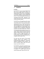
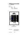
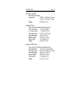
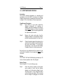
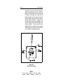
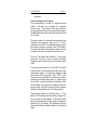
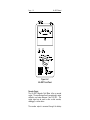
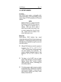
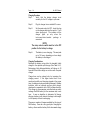
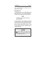
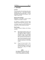
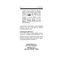
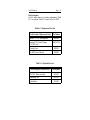
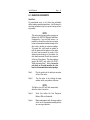
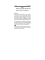
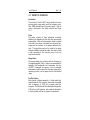
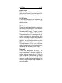
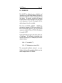
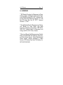
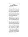
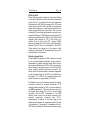
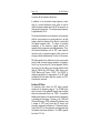
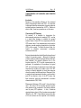
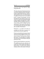
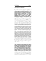
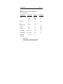
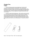
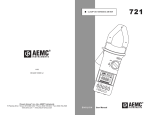
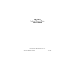
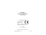
HIn3637
VLF Magnetic Field Meter
User's Manual
Copyright
© 1993 by Holaday Industries, Inc.
Manual #600055 2/00
$12.50
Revision Record
Manual #600055
HIn3637 VLF Meter
Revision
--A
B
C
D
Description
Release
Rev. Spec
Added CE Label
Update Recorder Output Level
Changed Area Code
Date
9/93
4/94
10/97
01/00
2/00
TABLE OF CONTENTS
1.0
DESCRIPTION . . . . . . . . . . . . . . . . . . . . .
1
Introduction . . . . . . . . . . . . . . . . . . . . . . . . 1
2.0
SPECIFICATIONS . . . . . . . . . . . . . . . . . . .
3.0
ACCEPTANCE AND CONTROLS . . .
Introduction . . . . . . . . . . . . . . . . .
Unpacking and Acceptance . . . . . .
Battery . . . . . . . . . . . . . . . . . . . .
Battery Charger . . . . . . . . . . . . . .
Controls, Indicators and Connectors
Recorder Output . . . . . . . . . . . . . .
Low Battery Indication . . . . . . . . . .
.
.
.
.
.
.
.
.
.
.
.
.
.
.
.
.
.
.
.
.
.
.
.
.
.
.
.
.
.
.
.
.
.
.
.
.
.
.
.
.
4.0
BATTERY CHARGING . .
Introduction . . . . . . . . .
Battery Tips . . . . . . . . .
Charging Procedure . . . .
Charging Considerations
Battery Replacement . . .
.
.
.
.
.
.
.
.
.
.
.
.
.
.
.
.
.
.
.
.
.
.
.
.
.
.
.
.
.
.
.
.
.
.
.
.
.
.
.
.
.
.
.
.
.
.
.
.
.
.
.
.
.
.
13
13
13
14
14
15
5.0
MAINTENANCE . . . . . . . . . . .
Introduction . . . . . . . . . . . . . .
Maintenance Recommendations
Return Procedures . . . . . . . . . .
Periodic/Preventive Maintenance
Parts Information . . . . . . . . . .
.
.
.
.
.
.
.
.
.
.
.
.
.
.
.
.
.
.
.
.
.
.
.
.
.
.
.
.
.
.
.
.
.
.
.
.
.
.
.
.
.
.
.
.
.
.
.
.
17
17
17
17
18
19
6.0
MAKING MEASUREMENTS . . . . . . . . . . .
Quick Start . . . . . . . . . . . . . . . . . . . . . .
Description . . . . . . . . . . . . . . . . . . . . . .
21
21
22
.
.
.
.
.
.
.
.
.
.
.
.
.
.
.
.
.
.
.
.
.
.
.
.
.
.
.
.
.
.
3
7
7
7
7
7
9
10
11
7.0
THEORY OF OPERATION
Introduction . . . . . . . . .
Probe . . . . . . . . . . . . .
Range Select . . . . . . . .
Pre-filter Section . . . . . .
Integrator Section . . . . .
Post-filter Section . . . . .
RMS Calculation . . . . . .
Power supply . . . . . . . .
.
.
.
.
.
.
.
.
.
.
.
.
.
.
.
.
.
.
.
.
.
.
.
.
.
.
.
.
.
.
.
.
.
.
.
.
.
.
.
.
.
.
.
.
.
.
.
.
.
.
.
.
.
.
.
.
.
.
.
.
.
.
.
.
.
.
.
.
.
.
.
.
.
.
.
.
.
.
.
.
.
.
.
.
.
.
.
.
.
.
23
23
23
23
23
25
25
25
25
8.0
CALIBRATION . . . . . . . . . . . . . . . . . . . .
27
9.0
REFERENCES . . . . . . . . . . . . . . . . . . . . .
29
APPENDIX A
VIDEO DISPLAY TERMINALS (VDTs) . . . . .
VDT CHARACTERISTICS . . . . . . . . .
General Description . . . . . . . . .
Principles of Operation . . . . . . .
Modulated DC Fields . . . . . . . .
60/50 Hz Fields . . . . . . . . . . .
Deflection System Fields . . . . .
Broadband RF Fields . . . . . . . .
CHARACTERIZING VDT EMISSIONS
OPERATOR EXPOSURE . . . . . .
Introduction . . . . . . . . . . . . . .
Characterizing VDT Emissions . .
GUIDELINES FOR RF EXPOSURE . . . .
.
.
.
.
.
.
.
.
.
.
.
.
.
.
.
.
.
.
.
.
.
.
.
.
.
.
.
.
.
.
.
.
.
.
.
...
....
....
....
...
...
...
...
AND
....
....
....
....
31
31
31
31
32
33
33
34
35
35
35
37
Limited Warranty
Holaday Industries, Inc. warrants each model HIn3637 3Axis VLF Magnetic Field Meter to be free from defects in
material and workmanship for a period of one year from
the date of shipment to the purchaser. This warranty
extends to the original purchaser only, and does not apply
to the batteries or to any products or parts subject to
misuse, neglect, accident, unauthorized service or
abnormal conditions of operation.
In the event an instrument covered by this warranty fails,
Holaday Industries, Inc. will, without charge, repair and
recalibrate the instrument if returned to their factory
within one year of the original purchase—provided that
Holaday Industries' examination discloses, to its
satisfaction, that the product is defective. Holaday
Industries, Inc., may, at its option, replace the product in
lieu of repair. If the defect was caused by misuse,
neglect, accident, unauthorized service or abnormal
conditions of operation, repairs will be billed at a nominal
cost. In such cases, an estimate will be provided before
work is started, if requested by the purchaser.
For warranty service, contact Holaday Industries, Inc.
Provide the serial number of the instrument and complete
details regarding the failure mode. You will then be given
either service information or shipping instructions. Return
the instrument to the factory, transportation prepaid.
Repairs will be made at the factory and the instrument
will be returned to you, transportation prepaid. Holaday
Industries, Inc., assumes no responsibility for loss of, or
damage to, products in transit.
Warning!
EXTREME CAUTION IS ADVISED WHEN WORKING IN
ENVIRONMENTS WHERE CONTACT WITH HIGH VOLTAGE OR HIGH
CURRENT CIRCUITS OR APPARATUS IS POSSIBLE.
THIS IS
PARTICULARLY TRUE WHEN ATTEMPTING TO OBTAIN ELECTRIC OR
MAGNETIC FIELD STRENGTH MEASUREMENTS IN CONFINED
QUARTERS SUCH AS INSIDE CABINETS CONTAINING ELECTRICALLY
OPERATED EQUIPMENT, ELECTRIC POWER SUBSTATIONS OR IN
VERY CLOSE PROXIMITY TO THE CONDUCTORS OF ENERGIZED
POWER LINES.
ACCIDENTAL CONTACT WITH OBJECTS OR
CIRCUITS OPERATED AT HIGH VOLTAGES OR HIGH CURRENTS CAN
BE LETHAL! HOLADAY INDUSTRIES, INC. ASSUMES NO LIABILITY
HIn3637 Manual
1.0
Page — 1
DESCRIPTION
Introduction
The HIn3637 VLF (very-low frequency) Magnetic Field
Meter measures magnetic field flux density in the
frequency range of 2 kHz to 400 kHz. The capabilities of
this instrument are designed to conform to the guidelines
issued recently in Sweden—as well as the IEEE P-1140
protocol—for measuring VLF magnetic fields produced by
video display terminals (VDTs). Applications for this
versatile meter range from VDTs and computer monitors
to high current factory locations.
The HIn3637 is a self-contained three-axis flux density
meter designed to respond to either sinusoidal or complex
magnetic field waveforms, such as those produced by the
vertical deflection system of a VDT. The meter circuit
utilizes a microprocessor to continually compute the rootmean-square (RMS) value of magnetic field flux density
and display it directly on an analog meter, allowing quick
assessment of the actual flux density value. The size of
the instrumentation/readout package was chosen for two
reasons. The first is to allow for two layers of electric and
magnetic shielding in addition to the outer housing. The
second is to allow for hand held operation. This
portability makes the HIn3637 particularly useful in
surveying the magnetic field flux density distribution over
a large area in a short amount of time.
The probe sensor array consists of three mutually
orthogonal multi-turn loops connected to the
instrumentation/readout package via a 1.5 meter cable.
Readings are independent of probe orientation. The
probe is electrically shielded, making the HIn3637
immune to most electric field effects.
The HIn3637 has a wide dynamic measurement range:
4 nT to 400 :T (100 dB). This makes the HIn3637
convenient for finding VLF magnetic field distributions in
any application. The supplied alternate panel label
converts the meter scale to Gauss (0.04 mG to 4 G).
Page — 2
HIn3637 Manual
The optional X100 probe shifts the measurement range
to 400 nT to 40 mT (6 mG to 400 G). An optional kit
converts the HIn3637 to indicate fields in field strength
units of amps/meter (A/m). See table 5-2 for optional
equipment.
HIn3637 Manual
2.0
Page — 3
SPECIFICATIONS
Frequency
Response: 2 kHz
400 kHz
< 2 kHz
> 400 kHz
- 3 dB
- 3 dB
80 dB/decade rolloff
40 dB/decade rolloff
Figure 8n1
HIn3637 Response Curve
Detector Response:
True RMS field indication for
accurate measurement of
non-sinusoidal waveforms.
Dynamic Range:
100 dB
Page — 4
Ranges:
Standard:
Alternate Scale:
With A/m option:
HIn3637 Manual
40 nT, 400 nT, 4 :T, 40 :T,
400 :T full scale*
0.4 mG, 4 mG, 40 mG, 400
mG, 4 G full scale*
30 mA/meter, 300
mA/meter, 3 A/meter, 30
A/meter, 300 A/meter full
scale*
Multiply all values by 100 when using the optional X100
probe
*
Accuracy:
±
5%
frequency
Linearity:
± 2% Full Scale
Recorder Out Level:
0 - 2.5
maximum
Recorder Out Jack:
¼ inch stereo phone jack
Battery:
12 VDC, 1400 mA-h
rechargeable Nickel-Cadmium
(NiCd)
Battery Life:
Approximately 20 Hrs.
continuous operation
(full charge)
Battery Charger:
110/220 VAC, 16 hour
Environmental Operating
Temperature:
Humidity:
at
calibration
VDC, 2 5
:A
0°C to 50°C (+32°F to
+122°F)
5% to 95% relative humidity,
noncondensing
HIn3637 Manual
Page — 5
Instrument Package:
Dimensions (Including
connectors):
165 mm x 95 mm x 70 mm
(6.5 in x 3.75 in x 2.75 in)
Weight:
0.88 kg (31 oz)
Standard Probe:
Type: External, three-axis multi-turn loop
I. D. (each loop):
110 mm (4.33 in)
O. D. (each loop):
116 mm (4.57 in)
Area (each loop):
0.010 m² (15.5 in²)
Overall Diameter:
127 mm (5 in)
Handle Length:
292 mm (11.5 in)
Cable length:
1.5 meters (5 ft)
Weight:
0.45 kg (16 oz)
Optional X100 Probe:
Type: External, three-axis single-turn loop
Loop Dimension:
12.7 mm (.5 in) per side
Area (each loop):
6.35 mm² (.25 in²) per side
Overall Diameter:
34.3 mm (1.35 in)
Overall Length:
292 mm (11.5 in)
Cable length:
1.5 meters (5 ft)
Weight:
0.31 kg (11 oz)
Page — 6
HIn3637 Manual
HIn3637 Manual
Page — 7
3.0 ACCEPTANCE AND CONTROLS
Introduction
This section contains information on: unpacking and
acceptance of the HIn3637; the battery; the battery
charger, and; all controls, indicators and connectors (refer
to figure 3n2 for the location of these components).
Unpacking and Acceptance
Step 1.
Upon delivery of your order, inspect the
shipping container(s) for evidence of
damage. Record any damage on the delivery
receipt before signing. In case of concealed
damage or loss, retain the packing materials
for inspection by the carrier.
Step 2.
Remove the meter and probe from the
shipping containers. Save the boxes and any
protective packing materials for future use.
Step 3.
Check all materials against the packing list to
verify that the equipment received matches
that which was ordered. If you find any
discrepancies, note them and call Holaday
Customer Service for further instructions.
Be sure that you are satisfied with the contents of your
order and the condition of your equipment before using
the meter.
Battery
The 12 VDC, 1400 mA-h NiCd battery provides up to 20
hours of meter operation when fully charged.
Battery Charger
Refer to Figure 3n1 for the following step.
Step 1.
Check the viewing window on the power
entry module to verify that the battery
charger is set to the proper voltage for your
AC power source. If not, change the setting
via the following procedure: After ensuring
that the charger is unplugged, use a small
Page — 8
HIn3637 Manual
screwdriver to pry loose the fuse assembly,
which is located below the AC connector.
Remove the assembly and locate the small
PC Board on the back side. Slide the PC
board from right to left to remove it from the
fuse assembly: rotate this board so that the
desired voltage indicator is right-side up,
then reinsert it into the fuse assembly. The
required voltage should now be visible in the
viewing window. Firmly reseat the fuse
assembly back into the power entry module.
The charger is now ready to use. See section
4 for the battery charging procedure.
Figure 3n1
End View of Charger
NOTE:
If the correct voltage is still not visible,
contact Holaday Customer Service for
HIn3637 Manual
Page — 9
assistance.
Controls, Indicators and Connectors
The instrumentation is housed in a rugged aluminum
chassis. The entire unit is shipped in a convenient
carrying case. The protective foam liner inside the
carrying case has cutouts which accommodate the meter,
the detachable probe and the optional accessories offered
for the meter.
The probe consists of a sensing head containing three
orthogonal coils oriented to pick up the X, Y, and Z
components of the field. The detachable probe plugs into
the multi-pin connector mounted on top of the chassis.
The color coded label surrounding the probe connector
will match the color of the band on the probe cover.
The top of the chassis also contains a ¼ inch stereo
phone jack. The jack is used to connect the battery
charger and also provide access to the recorder output
signal.
The rotary selector switch on the HIn3637 front panel
controls power to the instrument and selects one of five
measurement ranges. The scales are arranged so that
when turned to the first position—400 :T/4 G (or 300
Amps/meter if the optional kit is installed)—the meter is
measuring on its least sensitive scale, i.e., highest range.
As the switch is rotated clockwise, the sensitivity of the
meter increases. As a general rule, readings will be most
accurate when the meter movement shows maximum
deflection without lighting the Over Range indicator.
There are two indicators on the front panel. A "Low
Battery" LED illuminates when the battery voltage is too
low to provide accurate readings. At this point, testing
should be discontinued and the battery recharged or
replaced. The "Over Range" LED illuminates when the
measured flux density exceeds full scale for the selected
range.
Page — 10
HIn3637 Manual
Figure 3n2
HIn3637 Front Panel
Recorder Output
The HIn3637 Magnetic Field Meter offers a recorder
output. The recorder signal level is proportional to meter
deflection, and varies between 0 and 2.5 VDC. This
output signal can be used to drive a chart recorder,
datalogger, or other device.
The recorder output is accessed through the battery
HIn3637 Manual
Page — 11
charger connector (refer to Figure 3n3). This is a twoconductor jack that mates with a standard ¼ inch stereo
phone plug. The ring of the phone plug is reserved for
battery charger input and the tip is connected to the
recorder output. The shaft of the plug is common
ground. A diode in the charging circuit isolates the
battery voltage from the recorder output when the plug
is inserted into the jack.
Figure 3n3
¼ inch Stereo Phone Plug
The same circuit drives both the meter movement and the
recorder output. The maximum recorder output current
is 25 microamperes, requiring a 100 KS minimum
recorder output load; a lower impedance will affect the
accuracy of both the meter reading and the recorder
output voltage.
Both the meter movement and recorder output are driven
by a (PWM) pulse-width modulated signal from the
microprocessor. This leads to a small amount of ripple.
Low Battery Indication
The HIn3637 Magnetic Field Meter includes a "Low
Battery" indicator (LED) mounted on the front panel (refer
to Figure 3n2). It is normal for this LED to flash briefly
when switching ranges and when turning the instrument
off.
If the "Low Battery" indicator remains on during
operation, the battery must be recharged. When the
"Low Battery" LED lights, testing should be discontinued
Page — 12
HIn3637 Manual
and the battery recharged or replaced. This is due to the
output characteristic of NiCd batteries: the voltage
remains relatively constant until the battery is almost
completely depleted, then drops very rapidly.
HIn3637 Manual
Page — 13
4.0 BATTERY CHARGING
Introduction
Each HIn3637 meter contains a rechargeable nickelcadmium (NiCd) battery. A fully-charged battery (nominal
output voltage of 12 VDC) provides up to 20 hours of
operation.
NOTE:
Holaday Industries, Inc., charges the internal
NiCd battery of the HIn3637 at the factory in
order to calibrate the instrument prior to
shipment. While every effort is made to
ensure that your meter arrives ready to use,
we cannot guarantee that this will be the
case. Always check the condition of the
meter's battery prior to use.
Battery Tips
Nickel-Cadmium (NiCd) batteries have several
characteristics that can affect both their performance and
operating life. The following tips advise you how to take
advantage of these characteristics to get the most out of
your meter's battery.
!
Although NiCd batteries are rated for operation in
temperatures from -20 °C to +65 °C (-4 °F to
+140 °F), using the meter in extreme temperatures
will reduce operating time significantly.
The
optimum operating temperature range for these
batteries is +20 °C to +30 °C (+68 °F to +86
°F).
!
The battery in the HIn3637 does not require
periodic "deep discharges" to reverse the capacitydepleting "memory effect" caused by repeated
shallow discharges; however, undercharging can
reduce battery capacity.
!
If the battery appears unable to acquire or maintain
an appreciable charge, individual cells in the battery
may be shorted or damaged. If, for any reason, you
need assistance replacing your battery contact
Holaday Customer Service.
Page — 14
HIn3637 Manual
Charging Procedure
Step 1.
Verify that the battery charger is set
correctly for the AC voltage in your area.
Step 2.
Plug the charger into a suitable AC source.
Step 3.
Set the meter switch to OFF. Insert the plug
on the charger cable into the meter's ¼ inch
stereo phone jack. The indicator on the
charger lights up only when the
instrumentation/readout package is
connected.
NOTE:
The rotary selector switch must be in the OFF
position for the battery to charge.
Step 4.
The battery is now charging. This may take
up to 16 hours, depending on how deeply
the battery is discharged.
Charging Considerations
Recharge the battery using either the standard trickle
charger or the optional quick charger (See Table 5n2).
Recharging a fully discharged battery will take up to 16
hours with the trickle charger or one hour with the quick
charger.
Charge time can be reduced only by increasing the
charging current. If this higher current level is not
monitored carefully and charging stopped at the proper
time, the battery may be permanently damaged. Holaday
Industries offers an optional one-hour quick charger,
developed in cooperation with a NiCd cell manufacturer.
This charger is microcomputer controlled and can safely
recharge the NiCd battery (at the maximum rate) in one
hour. It uses an algorithm to determine full charge,
allowing a battery in any state of discharge to be brought
to full capacity without overcharging.
There are a number of chargers available for this type of
NiCd battery. Some do a very good job of charging the
battery, others sacrifice battery life for decreased charge
HIn3637 Manual
Page — 15
time. The HIn3637 should be charged only with an
approved battery charger.
Battery Replacement
A NiCd battery powers the HIn3637 Magnetic Field
Meter (See Table 5n1). In the event of battery failure, a
new battery can be obtained from Holaday Industries.
NOTE:
A #0 Phillips screwdriver works well for the
following procedure.
To replace the battery, remove the eight screws located
around the lip of the meter's front panel, pull the panel
away from the chassis and unplug the battery connector.
Remove the battery retainer and the old battery. Install
the new battery and reverse the above steps to
reassemble the meter.
CAUTION
Never short the terminals of a NiCd battery (even a
discharged battery). The resulting current may be excessive
and cause the lead wires to become extremely hot, which
can result in severe burns and/or fire.
Page — 16
HIn3637 Manual
HIn3637 Manual
Page — 17
5.0 MAINTENANCE
Introduction
This section explains which maintenance tasks can be
performed by the user. It also provides information
regarding replacement and optional parts. If you have
any questions concerning probe maintenance, consult
Holaday Customer Service.
Maintenance Recommendations
Maintenance of the HIn3637 is limited to external
components such as cables or connectors.
Any calibration or maintenance task which requires
disassembly should be performed at the factory. Check
with Holaday Customer Service (952-934-4920) before
opening the unit as this may affect your warranty.
Return Procedures
To return an instrument to Holaday, use the following
procedures:
Step 1.
Briefly describe the problem in writing. Give
details regarding the observed symptom(s),
and whether the problem is constant or
intermittent in nature. If you have talked
previously to Holaday Customer Service
about the problem, provide the date(s), the
name of the service representative you spoke
with, and the nature of the conversation.
Include the serial number of the item being
returned.
Step 2.
Package the instrument carefully. Use the
original carrying case, if possible. If not, use
the Parts List in Table 5n1 to order a new
case and foam packing from Holaday
Industries, Inc.
NOTE:
If your meter is calibrated in accordance with
MIL-Std-45662A, it is greatly to your benefit
to retain the original shipping box and packing
Page — 18
HIn3637 Manual
materials. One of the criteria for certifying a
calibration to MIL standards requires Holaday
Industries to always ship equipment in the
specified packaging. When a MIL Standard
instrument is sent to Holaday in other
packaging, we must replace it with the
specified packaging materials for return
shipment. YOU WILL BE BILLED FOR THE
NEW PACKAGING.
If the instrument is under warranty, refer to the Limited
Warranty at the front of this manual for additional
information about your return.
Periodic/Preventive Maintenance
The HIn3637 requires an annual calibration check to
verify that it is performing within specifications. This
calibration check may be performed by Holaday Service
Personnel at the factory. Return your meter(s), using the
original packing materials (if possible), to:
Holaday Industries Inc.
Attn. Service Department
14825 Martin Drive
Eden Prairie, MN USA 55344
HIn3637 Manual
Page — 19
Parts Information
Use the tables below for ordering replacement (Table
5n1) or optional (Table 5n2) parts for the HIn3637.
Table 5n1. Replacement Parts List
Part Description (Replacement Parts)
Part Number
Battery, 12 VDC, Rechargeable
Universal 12V Trickle Charger
(110/220 Volt)
491069
491063-05
Carrying Case
491085
HIn3637 User's Manual
600055
Table 5n2. Optional Parts List
Part Description (Optional Parts)
Part Number
X100 VLF Probe Assembly
491076
Amps/meter Kit
651006
Probe Mount
491050
Page — 20
HIn3637 Manual
HIn3637 Manual
Page — 21
6.0 MAKING MEASUREMENTS
Quick Start
For experienced users, or for those who particularly
dislike reading operating descriptions, the following is a
quick start procedure to get you up and running as soon
as possible:
NOTE:
This meter uses the same probe connector as
Holaday's HIn3627 ELF Magnetic Field Meter.
Consequently, if you use both meters, it is
possible to connect the probe from one meter
to the instrumentation/readout package of the
other meter, resulting in erroneous readings.
To prevent this, color bands are placed on
both the probe and the readout: on the probe,
the color band surrounds the center of the
spherical probe housing; on the readout, the
color band surrounds the multi-pin connector
at the top of the chassis. The colors used are
orange (HIn3627) and yellow (HIn3637).
When performing Step 1, below, be sure the
color band on the probe matches the color
band on the instrumentation/readout package.
Step 1.
Plug the probe into the multi-pin connector
at top of the meter.
Step 2.
Turn the meter on by rotating the range
selector switch one position clockwise.
NOTE:
The Battery Low LED will flash momentarily
when the meter is turned on.
Step 3.
Verify that neither the Over Range nor
Battery LEDs are illuminated.
Step 4.
Make measurements with the range selector
switch set for the maximum reading without
an over range indication.
Page — 22
HIn3637 Manual
NOTE:
The meter will not operate when the battery
charger is connected to the charger jack.
Description
To begin making field measurements, connect the probe
to the meter.
Turn the range switch clockwise,
increasing the instrument's sensitivity until an up-scale
meter reading is obtained. Readings will be most
accurate when the selected range yields maximum needle
deflection without lighting the Over Range LED. When an
over range indication occurs, select the next larger range.
Since the meter movement is protected against deflection
past the top of the meter scale, the "Over Range" LED
must be used to determine an over range condition.
The probe utilizes three mutually-perpendicular concentric
coils it is not necessary to rotate the sensor to obtain a
maximum indication on the meter.
HIn3637 Manual
Page — 23
7.0 THEORY OF OPERATION
Introduction
The circuitry of the HIn3637 can be divided into seven
sections: probe, range select, pre-filter, integrator, postfilter, RMS calculation and the power supply. Each of
these is discussed in the follow sections (see Figure
7n1).
Probe
The probe consists of three orthogonal concentric
shielded coils aligned such that their axes are mutually
perpendicular. Each coil's electrostatic shield is isolated
from that of the others: the shields are connected at a
single point at the base of the sphere defined by the
coils. The signal from each coil is routed to the meter
through a shielded twisted-pair cable: this cable's shield
is also connected to the common point of the coil
electrostatic shields.
Range Select
The output voltage of a coil varies with the frequency of
the applied magnetic field. In order to accommodate the
magnetic field amplitudes and frequencies that the
HIn3637 is designed to measure, a set of selectable
attenuators is used to ensure that the input voltage to the
remaining circuitry is at the proper level for the selected
range.
Pre-filter Section
Each channel is filtered separately. A fourth-order highpass Butterworth filter is used to insure that only signals
with a frequency of 2000 Hz or greater reach the
integrator. The Butterworth filter attenuates the signal by
3 dB at the cutoff frequency, has maximum attenuation
in the stop band, and has no ripple in the passband.
Page — 24
HIn3637 Manual
Figure 7n1
Block Diagram
HIn3637 Manual
Page — 25
Integrator Section
The output voltage of the probe sensor coils increases
directly with the frequency of the applied magnetic field.
The integrator provides a flat frequency response.
Post-filter Section
A second-order Butterworth low-pass filter ensures that
only signals below 400 kHz are fed to the RMS
calculation section.
RMS Calculation
The signal from each channel is applied to a separate true
RMS converter and combined through vector addition to
obtain the field magnitude. This value is computed by
the processor and A/D converter. The meter is driven by
outputs configured as a PWM (Pulse-Width Modulator).
The processor performs an A/D conversion on each axis
signal by programming the analog multiplexer, which
feeds the A/D converter. The digital values are squared
and summed; then the square root of the sum is
calculated. This result determines the duty cycle of the
PWM output, which drives the meter movement. The
PWM output frequency is 30 Hz; this is too high to be
visible on the analog meter, but it can be detected on the
recorder output as approximately 50 mV of ripple.
Power supply
A ten-cell NiCd battery powers the HIn3637. The
current consumption of the instrument is relatively low,
yielding a continuous operating time of 20 hours. In
typical daily operation (intermittent use), the operating
time between charges will be much greater. The voltages
required by the analog circuitry are derived directly from
the battery voltage. The digital voltage is supplied via a
series pass regulator.
Page — 26
HIn3637 Manual
HIn3637 Manual
Page — 27
8.0 CALIBRATION
The HIn3637 is calibrated using a Helmholtz coil
(consisting of two close-coupled windings) one meter in
diameter to establish an accurate, known magnetic field
flux density. A precisely controlled and measured
sinusoidal current is driven through the coils and, based
on the dimensions of the coils, the magnetic field flux
density between the coils is calculated.
Each axis is individually calibrated.
Calibration is
performed at a frequency of 20 kHz, and verified at 232
kHz, at a flux density level of 10 mG. The out of band
response is checked at 60 Hz and 700 kHz. All calibration
is traceable to NIST.
The HIn3637 indicates magnetic flux density (B) in units
of Tesla/Gauss. The flux density in microteslas or the
magnetic field strength (H) in milliamperes per meter are
related as follows:
1 mG = 0.1 microtesla (:T)
1 mG = 80 milliamperes per meter (mA/m)
The recommended calibration interval is one year.
Holaday Industries offers complete calibration services
which comply with MILnSTD 45662A.
Page — 28
HIn3637 Manual
HIn3637 Manual
Page — 29
9.0 REFERENCES
(1)
IEEE Standard Procedures for Measurement of Power
Frequency Electric and Magnetic Fields from AC Power
Lines. ANSI/IEEE standard 644n1987. Published by The
Institute of Electrical and Electronics Engineers, Inc., 345
East 47th Street, New York, NY 10017. Approved
November 17, 1986.
(2)
Swedish National Board for Measurement and Testing,
Test Methods for Visual Display Units—Visual
Ergonomics and Emission Characteristics. MPR 1990:8,
1990n12-01, National Board for Measurement and
Testing, Box 878, S-501 15 Bors, Sweden.
(3)
Electric and Magnetic Field Measurements and Possible
Effects on Human Health from Appliances, Power Lines,
and Other Common Sources. Special Epidemiological
Studies Program, California Department of Health
Services, 2151 Berkeley Way, Room 704, Berkeley, Ca.
94704 (415) 540-2669
Page — 30
HIn3637 Manual
HIn3637 Manual
Page — 31
APPENDIX A
VIDEO DISPLAY TERMINALS (VDTs)
VDT CHARACTERISTICS
General Description
Video display terminals (VDT's) and television receivers
are quite similar in certain respects. Both are used to
display information; the VDT displaying information
received from a computer system, word processing
system, or other digital information system and the
television receiver displaying video information
transmitted from television broadcast stations.
In
conjunction with a keyboard, the VDT serves as the main
interface between the operator and a word processor,
computer, etc. Television receivers are sometimes used
in lieu of VDT's with home computer systems.
Principles of Operation
VDT's and television receivers use the same basic
principles of operation. Both contain a large evacuated
glass tube called a cathode-ray tube (CRT), or picture
tube in the case of television receivers. The CRT
contains a source of electrons (the cathode) at one end
and a fluorescent coating on the inside of the viewing
screen.
Electrons released from the cathode are
accelerated by a high voltage (typically in the range of 10
to 25 kilovolts) and are projected onto the fluorescent
material of the screen which then emits visible light when
it is struck by the fast-moving electrons. The CRT also
includes various electrodes for focusing the electron
beam and for scanning the beam across the fluorescent
screen. Electronic circuitry in the VDT modulates the
electron beam to produce the intended images on the
screen.
This circuitry leads to the production of
electromagnetic fields (emissions). There are four basic
aspects to the electrical environment of VDT emissions:
(1) 60/50 Hz modulated DC fields; (2) 60/50 Hz fields;
(3) RF fields associated with the horizontal and vertical
deflection systems; (4) broadband RF fields caused by the
digital electronic circuits which are associated with
character generation (Roy, et al, 1983).
Page — 32
HIn3637 Manual
Modulated DC Fields
To accelerate the electron beam toward the screen, a
high DC voltage is used. The high voltage is produced by
pulsing a transformer which has a high turns ratio and is
often derived from the deflection circuitry, though in
some cases it may have a higher frequency depending on
the character display system. The drive pulse is a square
wave which produces a high voltage secondary pulse that
is rich in harmonic content. The AC components of this
DC current pulse flow to ground via the capacitance
formed by the CRT screen and the resistive coating on
the outside of the CRT. This small capacitance provides
the filtering necessary for a smooth high voltage
accelerating potential. Roy, et al, (1983) have reported
that one method of reducing the AC component of the
DC field is to place an RC filter network between the high
voltage transformer output and the CRT. They found
that such a filter could, in some VDT's, reduce the AC
component of the DC field by as much as 50 dB (a factor
of over 300 times).
The modulated DC field is produced by the charge on the
face of the CRT and is largely confined to the front of the
unit. This field is highly variable, being affected by
humidity, capacitance between the CRT and external
objects and touching the CRT (Harvey, 1984a). Several
investigators have measured the strength of this DC field
and found values ranging from a few hundred volts per
meter to as high as 45 kV/m at the surface of the body
of an operator, and depending on the proximity of the
operator to the VDT, closer distances resulting in higher
measured incident DC fields (Olsen, 1981; Harvey,
1984b; Nylen, et al, 1984; Bracken, et al, 1985).
HIn3637 Manual
Page — 33
60/50 Hz Fields
These fields are caused primarily by the current flowing
in the vertical deflection coil and are nearly symmetrical
around the coil. It is produced by the same mechanism
that produces the DC field; the charge on the VDT screen
which produces the DC field is actually not constant but
builds up and decays by a small amount each time the
display is scanned by the electron beam. This occurs at
a nominal 60 Hz rate although harmonics may exist up to
several kHz (Harvey, 1983a). Measurements of the 60 Hz
emissions and harmonics by Stuchly, et al, (1983) found
magnetic field strengths of 100 to 200 mA/m at a
position 30 cm in front of the VDT. Harvey (1984b)
reported measured 60 Hz AC electric field strengths of
between 5 and 60 V/m in an investigation of five VDTs.
These relatively low values are in the range of other
commonly encountered 60 Hz appliances found in the
home and office environment.
Deflection System Fields
The principal RF component of VDT emissions is caused
by the so-called flyback transformer circuitry which is
responsible for a rapidly changing current which flows in
the horizontal deflection coils of the VDT and causes the
electron beam to be rapidly swept to the left side of the
screen, ready for another trace across the screen. The
rate at which the electron beam is scanned is dependent
on the particular design of the VDT but typically falls in
the range of 17 to 30 kHz. For television receivers, the
flyback frequency is approximately 15.75 kHz.
The flyback circuit is rich in harmonic production and any
instrument intended for accurate assessment of RF
exposure fields produced by VDT's must be capable of
true RMS measurement. The strong harmonic content of
the flyback signal means that it has a non-sinusoidal
waveform; the HIn3637 incorporates a true RMS
detector circuit which can accurately respond to the
complex waveforms observed near VDT's.
Approximately 95 percent of the total energy of the
flyback circuit emissions is contained within the first five
or six harmonics. Consequently, the bandpass of the HI3637 has been tailored to the necessary frequency range
Page — 34
HIn3637 Manual
to capture all the important harmonics.
In addition to the horizontal sweep-frequency circuit,
there is a vertical deflection circuit which is used to
deflect the electron beam down the CRT screen and in so
doing produce characters. The vertical sweep frequency
is approximately 60 Hz.
The horizontal deflection circuit operates on the principle
that the force exerted on a moving electron is at right
angles to both the direction of the electron's motion and
the applied magnetic field. To induce a horizontal
component to the electron's original direction, the
magnetic field must possess a vertical polarization. Thus,
the horizontal deflection coils in VDT's and television
receivers tend to generate magnetic fields which are
strongly vertically polarized near the front of the screen.
RF fields caused by the deflection circuitry can produce
electric fields at normal operator positions of typically a
few V/m up to some tens of V/m and magnetic fields in
the range of a few mA/m up to several hundred mA/m
(Harvey, 1983b; Guy, 1987; Boivin, 1986; Joyner, et al,
1984; Marha and Charron, 1983). The HI-3637 is
designed specifically for measurement of the RF fields
associated with the beam deflection systems in VDT's
and television receivers.
Broadband RF Fields
An electronic clock within the VDT which typically
operates in the frequency range of 1 to 20 MHz is the
source of most of the radiated RF signals from the digital
electronics sub-section (Roy, et al, 1983). Conventional
shielding techniques are the usual method for eliminating
or reducing such emissions. Petersen, et al, (1980) and
Weiss and Petersen (1979) evaluated RF emissions from
a number of VDT's and found that RF electric field
strengths, measured at a distance of 1.5 meters from the
front of the VDT, for those emissions not associated with
the flyback circuit were well below 1 V/m RMS, typically
less than 0.01 V/m.
HIn3637 Manual
Page — 35
CHARACTERIZING VDT EMISSIONS AND OPERATOR
EXPOSURE
Introduction
Because of the perturbing influence of the measured
electric field strength values near VDT's, it is important
to distinguish between assessments of operator exposure
and basic emission characteristics of VDT's. Relative to
electric fields, these two properties are not the same.
Characterizing VDT Emissions
On occasion it is desirable to characterize the
electromagnetic emissions of a number of VDT's, such as
in a large office situation, to establish the general
emission levels of these VDT's for comparison with other
VDT emission data. Such measurements can be used to
determine unusual operating characteristics of particular
VDT's within a group. To collect this type of data, it is
helpful to minimize unnecessary, extraneous
environmental factors.
Emission characterizations should therefore be performed
without the operator present. Although the literature
contains numerous methods by which emission data have
been obtained, the principal difference lies in the
locations about the VDT at which measurements are
performed. An exploration of the surfaces of a typical
VDT will reveal areas of particularly intense fields, but
these areas are usually on the sides or top of the VDT
and are not directly applicable to frontal area exposure
where the operator would be positioned. Because of this,
a nearly universal measurement location—positioned at a
point 30 cm directly in front of the VDT screen—has
been commonly used and recommended in emission
characterizations (FDA, 1984).
Measurement distances of 50 cm and 1 m have also been
used. The value of 30 cm actually represents a quite
close distance when compared to the viewing distance
used by many VDT operators. In fact, a minimum
viewing distance closer to 36 cm has been recommended
(Diffrient, et al, 1981). Nevertheless, because the value
of 30 cm has been so often reported in the literature,
Page — 36
HIn3637 Manual
measurements should at least include this distance
among possible others.
VDT emission data reported in the literature show that in
most instances a fixed screen condition has been used to
promote more repeatable measurements. For example, a
commonly reported method involves filling the screen
with a single character such as an E or M and adjusting
the brightness and contrast controls to their maximum
position. In contrast to these precautions, it has also
been reported that these measures often seem to have
very little, if any, impact on the resulting measured values
of electric and magnetic field strength (Roy, et al, 1983).
Nevertheless, because of peculiarities of some VDTs, a
check of the effect of varying the brightness and contrast
controls should be made. Roy, et al (1983), suggest that
CRT performance, which decreases with age, and the
type of video generating system used are two possible
factors responsible for this phenomenon.
Measurements of the magnetic field strength are
considerably less difficult since the presence of the
human body does not perturb the magnetic field.
Distances are measured between the screen surface and
the center of the probe for magnetic field values. As the
distance between the probe and the screen is decreased,
greater error will exist in the indicated value of magnetic
field strength. This spatial averaging error diminishes
rapidly with distance from the VDT since the field rapidly
becomes more uniform.
Because the magnetic field gradients are so great near the
VDT, significant error may occur if extra care is not
exercised when attempting repeated measurements at a
specific location. This is apparent when holding the
instrument without a tripod very near the screen and
attempting to obtain a constant reading of field strength.
HIn3637 Manual
Page — 37
GUIDELINES FOR RF EXPOSURE
To provide a means for judging the significance of
measured magnetic field emissions found near VDT's, the
scientific literature can be examined for information on
suggested exposure or emission limits. The exposure
standards reviewed at the time of this manual's
preparation apply to humans for the purpose of
establishing safe working or living environments where
magnetic fields exist. The exposure limits compiled in
this manual are those found that correspond most closely
to the predominant frequency range of VDT's. In some
cases, the standards apply to occupational exposure
environments and in other cases, to the general living
environment; often standards for this latter case are
referred to as general population or public exposure limits.
Traditional approaches to radiation protection, principally
derived from ionizing radiation protection practices,
usually differentiate between occupational and public
exposure. Generally, occupational exposure limits are
higher, i.e., more permissive, than public limits. This is
because of the greater uncertainties associated with the
general public; in the work place, employees are generally
healthier, and possible exposure to potentially hazardous
physical agents is usually under much better control. For
example, employers can inform workers of situations
which should be avoided; this is not the case for the
general population. Regardless of these considerations,
it is informative to examine some of the recommended
exposure guides that apply to different organizations
and/or countries.
Table 1 summarizes the electromagnetic field exposure
standards found in the literature that either directly apply
to the frequency range appropriate to VDT emissions or
pertain to a frequency range close to that of interest. As
can be seen, the primary difficulty in applying many RF
exposure standards to VDT emission levels is that the
applicable frequency range of the standards does not
extend low enough. From the literature searched, only
one reference was found that offered a quantitative
emission limit as a guideline specific to VDT's (Telecom,
Page — 38
HIn3637 Manual
1984). This Occupational Health Policy Guideline for
VDT screen-based equipment was developed by Telecom
Australia for internal use until such time as there is a
national standard for VDTs in Australia. The guide
specifies that the levels of radiation emitted from
cathode-ray VDT's in the frequency range of 50 Hz to
0.3 MHz shall be as low as possible, and should not, at
any time, exceed an electric field strength of 50 V/m,
measured 30 cm from the terminal.
The reader of this manual is cautioned that a number of
RF exposure standards are presently under development
or revision and that Table 1 should be used more as an
orientation to existing standards.
HIn3637 Manual
Page — 39
Table 1.
Radio Frequency Exposure/Emission Standards Pertinent to
the VDT Frequency Range.
Standard/Reference
Frequency (kHz)
E (V/m) RMS
H (gauss) RMS
ACGIH
0 ) 0.1
0.1 ) 4
4 ) 30
25000
2500/f(1)
625
--0.6/f(1)
---
IEEE C95.1
3 ) 100
614
2.05
50/60 (Hz)
5000
1.0
.005 ) 2
2 ) 400
25
2.5
.0025
.00025
UK(1986)(occ)
750 Hz - 50 kHz
2,000
1.25
UK(1986)(public)
750 Hz - 50 kHz
800
.05
25
---
IRPA
(gen. pop. 24 hr.)
Swedish
Guidelines(2)
USSR(public)
(Slesin, 1985)
(1)
(2)
0.03 - 0.3
Frequency in KHz
These guidelines are not based on biological effects.
They are based on what was technically possible.
Page — 40
HIn3637 Manual
-- NOTES --