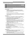
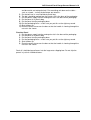
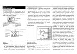
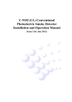
1
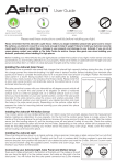
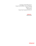
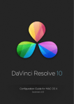
ACS
Control Panel Range
Owners Manual v1.4
Tangent Devices Ltd.
Jaltek Unit 13,
Dencora Way,
Luton, LU3 3HP, UK.
Tel: +44 (0) 1582 848100
Fax: +44 (0) 1582 848000
www.tangentdevices.co.uk
ACS Control Panel Range Owners Manual v1.4
Contents
1. Important safety instructions
2. About this manual
3. What’s in the box
4. Notes on the ACS range
5. Mounting the panel
6. Fitting the rings and balls to the trackerballs
7. Fitting the keyboard stand
8. Connecting the panel
9. IP addresses
10. Notes on hubs, switches, routers and Ethernet
11. ID Number
12. Installing the tablet drivers from the CD
13. Rear panel indicators
14. Test mode
15. Trouble shooting
16. Care of your panels
17. Re-packing the panel for shipping
2
3
3
4
4
7
7
8
9
9
9
9
11
12
13
14
15
1
ACS Control Panel Range Owners Manual v1.4
1. Important safety instructions
!
•
•
•
•
•
•
•
Please read the following important safety instructions before doing
anything with the panel.
Read this manual first before using the panel.
Keep this manual for future reference.
Take notice of any warnings in this manual.
Follow all instructions in this manual.
Do not use the panel near water.
Install and use the panel only as instructed.
Do not install near any heat sources such as radiators or other apparatus that
produce heat.
The external power supply must be earthed using an appropriate mains cord.
Unplug the panel when it’s not going to be used for long periods of time.
Refer all servicing to qualified personnel. Servicing is required when:
o The panel has been damaged in any way.
o Liquid has been spilled on the panel.
o Objects have fallen into the panel.
o The panel has been exposed to rain or moisture.
o The panel does not operate normally.
o The panel has been dropped.
•
•
•
!
This notice is applicable for USA/Canada only.
If shipped to USA/Canada, install only UL LISTED/CSA LABELLED power
supply cord meeting the following specifications:
SPECIFICATIONS:
Plug Type: Nema-Plug 5-15p
Cord: Type SVT or SJT, minimum 3 x 18 AWG
Length: Maximum 15 feet
Rating: Minimum 7 A, 125 V
2
ACS Control Panel Range Owners Manual v1.4
2. About this manual
This manual applies to all the panels in the ACS range. For the latest updates please
check www.tangentdevices.co.uk and look under Downloads: Documentation.
This manual does not tell you how to use the panel with your software. For that
information please contact Autodesk.
If you find any errors with this manual or you have any suggestions then please
contact Tangent Devices. It is only through your feedback and suggestions that we
can improve our services and products.
3. What’s in the box
In every box you will find:
1x
ACS Panel
1x
external power supply
Note: Tangent Devices do not supply mains leads to
connect the external power supply to your mains
supply.
In addition to these, the following panels will also include in their box:
Grading Panel
In the lid of the box you will find:
3x
trackerball rings
1x
tablet pen
1x
tablet driver CD
In the base of the box you will find:
3x
trackerball balls
1x
keyboard stand kit (see the section on fitting this for
kit contents)
3
ACS Control Panel Range Owners Manual v1.4
1x
tablet mouse
Navigation Panel
In the lid of the box you will find:
1x
trackerball ring
In the base of the box you will find:
1x
trackerball ball
4. Notes on the ACS range
There are 3 panels in the ACS range:
• Grading
• Navigation
• Function
The ACS range of control panels are built by Tangent Devices to a specification
provided by Autodesk. What function any of the controls have is not determined by
Tangent Devices, it is decided by Autodesk and the Autodesk software that you are
using the panels with.
5. Mounting the panel
Generally it is expected that the panels will be left free standing on a desk. But each
of the panels has a lip around the edge of it which will allow it to be fitted into a hole
cut in a desk. Care should be taken though not to foul the cables that exit from the
rear of the panel.
See the following drawings of the panel base to determine what size hole to cut in the
desk if you are going to mount it in this way.
Note that all the ACS panels are the same size, so the following drawings may be
used for all the panels.
!
Important: Tangent Devices except no responsibility for any use made of
these drawings and we strongly advise checking against the physical
panel before cutting any holes.
4
ACS Control Panel Range Owners Manual v1.4
ACS Panel Side View
5
ACS Control Panel Range Owners Manual v1.4
ACS Panel Bottom View
6
ACS Control Panel Range Owners Manual v1.4
6. Fitting the rings and balls to the trackerballs (Grading and Navigation panels only)
Fit the ball into the trackerball first. Then place the ring onto the trackerball and gently
push down applying and even pressure all round. The ring is held in place by friction
and can easily be removed later should you need to clean the ball.
7. Fitting the keyboard stand
The keyboard stand kit can be found in the base of the Grading panel box. It contains
the following:
1x
keyboard shelf
2x
keyboard brackets
4x
M3 x 10mm socket screws
6x
M3 x 6mm counter-sunk cross-head screws
1x
2.5mm Allen key
The keyboard stand can be fitted to any of the ACS panels using the following steps:
1.
Fit the brackets to the panel first. The four M3 x 10mm
socket screws are used to fit the brackets to the
panel. The 2.5mm Allen key should be used to tighten
the screws.
7
ACS Control Panel Range Owners Manual v1.4
Fit the shelf to the top of the brackets using the six M3
x 6mm counter sunk screws.
2.
8. Connecting the panel
On the rear of all the panels you’ll find two connectors, one labelled Ethernet and
one labelled 5V DC 4A. If your panel is a Grading panel then there will be a third
connector labelled Tablet.
5V DC 4A
This is the power supply input for the panel. The panel requires a supply of
5V DC, rated at 4A.
On the plug of the external power supply there is a red dot. This red dot
should be pointing down when the connector is plugged into the panel. Do not
force the connector, if t doesn’t seem to fit make sure the red dot is pointing
down.
!
Important: Only use the external power supply provided by
Tangent Devices. Failure to do this will void your warranty and
may be dangerous.
Ethernet
This is an RJ45 connector and uses standard Cat 5 wiring.
If you are using a hub you can use a straight-through patch cable (pin to pin).
If you are connecting the panel direct to a PC you may need to use a crossover cable. We have found that some PC’s automatically detect the type of
connection and will be happy with either a straight-through or a cross-over
cable.
Tablet (Grading panel only)
This is a USB connector and is the connection for the tablet in the panel.
8
ACS Control Panel Range Owners Manual v1.4
Standard USB regulations should be observed when connecting the host
computer to the tablet. Particular attention should be paid to the length of the
USB cable you use. This should be less than 5m.
Note that the tablet does not require the panel to be powered up to work.
9. IP addresses
The panels supports DHCP IP address assigning.
When DHCP is not used the IP address is given to the panel by the software you are
running the panel with. You will need to contact your Autodesk for instructions on
how to do this. You will need to use the panel ID number to set this up. See the
section on ID number for notes on this.
10. Notes on hubs, switches, routers and Ethernet
The panels all run 10Mb (mega-bit) Ethernet (10 Base-T).
Generally hubs are the simplest solution to networking the panel with the host system
running your software.
Some routers and switches will block broadcast Ethernet packets. The panels
sometimes need to be configured from the software you’re using the panel with. This
configuration will use broadcast packets. If you are using a switch or a router and
you’re having trouble communicating with the panel from your software, then try to
find a simple hub or try a direct cable from the host PC (see the section on
Connecting the panel: Ethernet). If the panel works under this simple test then it
will be your router or switch that is causing the problem, in this case see if there is a
setting which will enable / allow broadcast packets.
11. ID number
The ID number of the panel will be required if you are to set the IP address of the
panel from the software you are using the panel with. This ID number is unique to
each panel as is randomly set at the Tangent Devices factory.
The ID number is the last four digits of the serial number. You will find the serial
number on the rear of the panel. So for example, if the serial number of the panel is
060719-6-1-0079, then the ID number is 79 (ignore any leading zeros).
Alternatively the ID number is displayed on the display when the panel is first
powered up. The display will show something similar to:
Panel: Grading
Encoder:
=
Firmware: 4.2 ID: 79
Key:
=
In the above example the ID is the last two digits of the top line 79.
12. Installing the tablet drivers from the CD
Please follow any specific instructions provided by Autodesk for installing the tablet
drivers, but in general follow the steps below:
1) Make sure you have the tablet plugged in and have the tablet mouse on the
tablet when you do this.
2) Install the tablet driver off the CD included with the panel.
9
ACS Control Panel Range Owners Manual v1.4
3) Now go to the Windows Start menu (bottom left of the screen) and select
Programs, then select Tablet, and then Pen Tablet. This will call up the tablet
setup window.
4) Under the Pen tab, make sure Tracking is set to Pen Mode. Then click the Details
button next to this. The window that then opens gives you the options for how the
tablet is mapped to the monitor. Set this to your preference.
10
ACS Control Panel Range Owners Manual v1.4
5) Under the Tablet tab, make sure the Wheel Function is set to Disable Wheel
Function.
!
You must disable the tablet wheel function in the tablet setup. If you do
not do this you may get strange behaviour from scroll bars. You can
leave the tablet mouse scroll wheel enabled.
Note that there is a user manual for the tablet on the driver CD.
13. Rear panel indicators
On the rear of the panel there are a number of lights, these are used as follows:
System: This will flash about once a second if the panel is running properly.
Power: This will be on if power is connected to the panel.
Activity: This will be on and green if a valid Ethernet connection has been made.
Link: This will flash orange when Ethernet packets are received by the panel.
11
ACS Control Panel Range Owners Manual v1.4
14. Test mode
By default the panel will come up in a test mode when power is connected and no
Ethernet cable is plugged in. This helps trouble shoot if any of the controls are not
working.
To enter the Test Mode, do the following:
1) Turn the panel off by unplugging the power supply.
2) Remove any Ethernet cable that you have connected to the panel.
3) Turn the panel back on by plugging in the power supply.
The display will now show something similar to the following:
Panel: Grading
Encoder:
=
Firmware: 4.2 ID: 79
Key:
=
What you see will differ slightly, but basically lines above tell you the following:
Grading is the panel type.
4.2 is the version of the internal software (firmware) of the panel.
79 is the ID number of the panel.
Checking that the controls are working
If you move any of the controls or press any of the buttons the second line of
the display will change to show you the status of the control or button which
has been changed. The following describes what you should see for each
control or button:
Knobs
If you move a knob or a trackerball the second line of the display will
show something similar to this:
Encoder: 7 = 3
The first number is the ID number for that control, in this case 7. The
second number is the amount it’s moved by, in this case 3. The
number gets bigger the faster you turn the control. This should be
positive when the knob is turned clockwise and negative if turned anticlockwise. If the number is always -1 or 1, or doesn’t change then the
knob is faulty.
Buttons
If you press a button the second line of the display will show
something similar to this:
Key: 2 = DOWN
When you release the button it will show something similar to this:
Key: 2 = UP
If this doesn’t happen then the button is faulty.
12
ACS Control Panel Range Owners Manual v1.4
Trackerballs
Just like the knobs, moving the outside ring of the trackerball, or the
ball itself, will cause the second line of the display to show something
similar to this:
Encoder: 2 = 3
The first number is the ID number for that control, in this case 2. The
second number is the amount it’s moved by, in this case 3. The
number gets bigger the faster you turn the control. This should be
positive when the ring is turned clockwise, or the ball is moved to the
right or up. It will be negative if the ring is turned anti-clockwise, or the
ball is moved to the left or down. If the number is always -1 or 1, or
doesn’t change then the knob is faulty.
Note: due to the way the software scans the movements of the balls, it
will be hard to see only changes in the left / right direction. The up /
down movements are always displayed in preference by the test
mode, and as it’s difficult to move the ball in just the left / right
direction with out moving it up / down, you’ll always see mostly up /
down changes.
15. Trouble shooting
A button doesn’t work
Go into test mode and follow the button test procedure. If the button doesn’t
work in the test mode then the button is broken. In this case please contact
Autodesk.
If the button works in the test mode then it may be a problem with the
software you are using the panel with. Contact Autodesk.
It may also be an Ethernet communication problem. See the trouble shooting
Ethernet section.
A knob / trackerball doesn’t seem to work
Go into test mode and follow the knob test procedure. If the knob doesn’t
work in the test mode then the knob is broken. In this case please contact
Autodesk.
If the knob works in the test mode then it may be a problem with the software
you are using the panel with. Contact Autodesk.
It may also be an Ethernet communication problem. See the trouble shooting
Ethernet section.
System light doesn’t flash
Check there is power going to the panel. If there is power going to the panel
and the system light is not flashing then the panel is faulty. In this case please
contact Autodesk.
Power light isn’t on
First check that the power supply connector is fully inserted into the panel.
13
ACS Control Panel Range Owners Manual v1.4
Next, check that the light on the external power supply is on. If it’s not then
check that it’s plugged into the mains and that any fuses are ok.
If the light on the external power supply is on but the power light on the panel
is still not on, then the panel is at fault. In this case please contact Autodesk.
If the light on the external power supply is off but it is being supplied with
mains power then the external power supply is at fault. In this case please
contact Autodesk.
My software isn’t communicating with the panel
Generally problems with communication are related to setting up your
software to talk to the panel. Refer to your Autodesk instructions for doing
this.
Read the previous sections of this manual relating to the Ethernet connection,
hubs routers and switches, IP addresses and ID number.
Activity light: When you plug an Ethernet cable into the RJ45 connector on
the panel, and the other end of the cable is connected to a hub/host computer
that is powered on, the green LNK light on the RJ45 connector will light up. If
it does not light up then check the cable is not damaged and the connectors
are fully inserted into their plugs. Make sure the hub/host computer is
powered up.
Link light: When there is communication taking place with the host computer,
the ACT light will flash as the panel receives information. If it doesn’t flash
then make sure the ACT light is on (see above) and that the software is
running on the host computer and it has been set up to talk to the panel.
If after doing the above, and taking any relevant action, you’re still having
trouble, then contact Autodesk.
When using the pen the cursor jitters
Make sure you have the tablet drivers installed on the PC running your
software.
Make sure that you’re not using the panel close to a source of strong electro
magnetic radiation such as a CRT monitor.
When using the pen I get erratic responses from window scroll bars
In tablet set up software look under the Tablet tab, make sure the Wheel
Function is set to Disable Wheel Function. See the section on Installing the
tablet drivers from the CD.
16. Care of your panels
Your ACS panels should not be cleaned with harsh abrasives or chemical cleaning
products. If they become dirty wipe them with a soft damp cloth.
14
ACS Control Panel Range Owners Manual v1.4
17. Re-packing the panels for shipping
!
Should you need to ship the panels it is important that these instructions
are followed to prevent the panels being damaged in transit.
!
Do not ship the panels with the rings and balls fitted to the tracker balls.
Remove all cables from the panels.
Keyboard Stand
If the keyboard stand has been fitted to any of the panels this must be
removed first and dismantled into its three parts (the shelf and the two
brackets). This should be wrapped in bubble-wrap and placed in the base of
one of the Grading panel box.
Remember to include the screws in the packaging.
Be careful that when the panel is put in over the top of the bubbled-wrapped
keyboard stand it does not crush the stand or that the panel is not forced up
out of its packaging.
Grading Panel
1) Put the mouse in its box and place in the bottom of the packaging base.
2) Remove rings from trackerballs. This can be done by prizing the ring up with
two hands, getting your finger nails in under the ring’s edge.
3) Put the rings into their small individual plastic bags.
4) Pack the rings in the cut-outs in the packaging lid. Make sure you put the
foam cap back over the rings in the lid.
5) Remove the balls from the trackerballs. This can be done by using one hand
to hold two of the balls in place and tilting the panel over on its side. This
allows the free ball to fall out. Do this over a table top and be careful not to
drop the ball. Put something soft down on the table – such as a towel – so
that the ball drops out onto this.
6) Put the balls into their small individual plastic bags.
7) The balls should be packed into the circular slots in the base of the
packaging.
8) Put the power supply into the rectangular slot in the base of the packaging.
9) Put the panel in its plastic bag.
10) Put the panel into the packaging base.
11) Put the packaging lid on – make sure you put this on the right way round.
12) Put the tablet pen in its slot in the packaging lid.
13) Shut the box up.
14) Place the outer sleeve over the box so that the handle is showing through the
cut-out in the sleeve.
Navigation Panel
1) Remove ring from trackerball. This can be done by prizing the ring up with
two hands, getting your finger nails in under the ring’s edge.
2) Put the ring into its small individual plastic bag.
3) Pack the ring in the cut-out in the packaging lid. Make sure you put the foam
cap back over the ring in the lid.
4) Remove the ball from the trackerball. This can be done by tilting the panel
over on its side. This allows the free ball to fall out. Do this over a table top
15
ACS Control Panel Range Owners Manual v1.4
and be careful not to drop the ball. Put something soft down on the table –
such as a towel – so that the ball drops out onto this.
5) Put the ball into its small individual plastic bag.
6) The ball should be packed into the circular slot in the base of the packaging.
7) Put the power supply into the rectangular slot in the base of the packaging.
8) Put the panel in its plastic bag.
9) Put the panel into the packaging base.
10) Put the packaging lid on – make sure you put this on the right way round.
11) Shut the box up.
12) Place the outer sleeve over the box so that the handle is showing through the
cut-out in the sleeve.
Function Panel
1) Put the power supply into the rectangular slot in the base of the packaging.
2) Put the panel in its plastic bag.
3) Put the panel into the packaging base.
4) Put the packaging lid on – make sure you put this on the right way round.
5) Shut the box up.
6) Place the outer sleeve over the box so that the handle is showing through the
cut-out in the sleeve.
Pack all 3 individual panel boxes into the large outer shipping box. Do not ship the
panels in just their individual boxes.
16