1
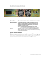
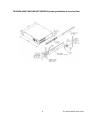
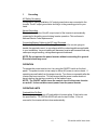
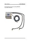
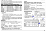
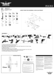
TRANSDUCTION
USER’S MANUAL
Version 1.0
10/20/08
TR-1000VA-48VDC Pure Sine Wave Inverter
48 V DC to 120 V AC 50/60 Hz
5155-23 Spectrum Way, Mississauga, ON, Canada L4W 5A1
TEL: 1-800-268-0427, 905-625-1907
FAX: 905-625-0531
Email: [email protected]
Important Information
The information in this document is subject to change without notice.
All relevant issues have been considered in the preparation of this document.
Should you notice an omission or any questionable item in this document, please
feel free to notify Transduction.
Regardless of the foregoing statement, Transduction assumes no responsibility
for any errors that may appear in this document nor for results obtained by the
user as a result of using this product.
Copyright © 2005 Transduction. All rights reserved.
This document is protected by copyright. No part of this document may be reproduced, copied or translated in any form or means without prior written permission
from Transduction.
All other trademarks, brand and product names are the property of their respective owners.
Return policy
Warranty is 3 years from the date of purchase. Products returned for repair must
be accompanied by a Return Material Authorization (RMA) number, obtained from
Transduction prior to return. Freight on all returned items must be prepaid by the
customer. The customer is responsible for any loss or damage caused by the
carrier in transit.
To obtain an RMA number, call us at 905-625-1907. We will need the following
information:
·
Return company address and contract
·
Model name, model number and serial number
·
Description of the failure
Mark the RMA number clearly on the outside of each box, include a failure report
and return the product to:
Transduction
5155 – 23 Spectrum Way
Mississauga ON Canada L4W 5A1
Attn: RMA Department
Index
Safety Precautions ..............................................................4
General Features ................................................................ 5
Introduction ........................................................................ 5
Rear View Rack Mount Version ............................................ 6
Quick Hookup and Testing ................................................... 7
Installation ......................................................................... 8-10
TR-1000VA-48VDC Rack Mount Version ............................. 9
Operation........................................................................... 10-11
Troubleshooting................................................................... 11
Maintenance........................................................................12
Specifications......................................................................13
For Service and Support Contact......................................... 14
Safety Precautions
WARNING!
Before installing and using the inverter, please read the safety precautions.
General Safety Precautions
Do not expose the inverter to rain, snow, spray, bilge or dust. To reduce risk of
hazard, do not cover or obstruct the ventilation openings.
To avoid risk of fire and electrical shock, make sure that existing wiring is in good
electrical condition and that wire size is not underrated. Do not operate the
inverter using damaged or substandard wiring.
Explosive Gas Precautions
This equipment contains components which can produce arcs or sparks. To
prevent fire or explosion, do not install inverter in any compartments containing
batteries or flammable materials, or in locations which require ignition protected
equipment. This includes any space containing gasoline powered machinery,
fuel tanks and any fittings or other connections between components of the fuel
system.
Precautions When Working with Batteries
If battery acid contacts skin or clothing, immediately wash with soap and water.
If acid enters the eye, immediately flush eye with cold, running water and keep
flushing it for at least 20 minutes. Seek medical attention immediately.
NEVER smoke, allow sparks or open flames near the battery or engine.
Do not drop metal tools on the battery. The resulting spark or short circuit may
cause an explosion.
Remove personal jewelry items when working with lead acid batteries. The short
circuit current produced is high enough to cause severe burns.
4
TR-1000VA-48VDC User Guide
GENERAL FEATURES
- Pure sinewave ouput (<2% THD)
- Input and ouput isolation
- High efficiency 87% ~ 90%
- High surge capacity inductive loads
- Soft start technology
- Frequency 50/60Hz switchable
- Auto restart
- 2U rack mount
- 3 year warranty
INTRODUCTION
The TR-1000VA-48VDC power inverter is one of the most advanced power
systems available. To get the most out of the power inverter, it must be
installed and used properly.
Please read the instructions in this manual before installing and using.
5
TR-1000VA-48VDC User Guide
REAR VIEW RACK MOUNT VERSION
Cooling Fans:
Battery Terminals:
Ground:
Do not obstruct. Allow at least 1 inch clearance for air flow
Check that the inverter voltage is compatible with your
supply i.e. a 48V inverter on a 48V system. Using the
spanner and cables provided, connect to 48V battery
or other 48V power source.
NOTE: Reverse polarity connection will blow internal
fuses and may permanently damage the inverter.
Chassis ground or to vehicle chassis using 8AWG wire.
NOTE: Operation without a proper ground connection may
result in electrical hazard.
SHOCK HAZARD WARNING!!
Before proceeding any further, ensure that the inverter is NOT connected to any
batteries and that all wiring is disconnected from any electrical sources. Do not
connect the output terminals of the inverter to an incoming AC source.
6
TR-1000VA-48VDC User Guide
QUICK HOOKUP AND TESTING
To check performance before proceeding with the installation, do the following:
1.
Unpack and inspect the inverter. Make sure the power switch is in the
OFF position
2.
Connect the cables to the power input terminals on the rear panel of the
power inverter. The red terminal is positive (+) and black terminal is
negative (-). Connect the cables into the terminals and tighten the wing
nut to clamp the wires securely.
3.
Connect the cable from the negative terminal of the inverter to the
negative terminal of the power source. Make a secure connection.
NOTE: Loosely tightened connectors result in excessive drop and
may cause overheated wires and melted insulation.
4.
Before proceeding further, double check that the cable you have just
connected to the negative terminal of the inverter is connected to the
negative output terminal of the power source.
NOTE: Reverse polarity connection will blow a fuse on the inverter
and may cause permanent damage. Damage caused by reverse
polarity connection is not covered under warranty.
5.
Connect the cable from the positive terminal of the inverter to the positive
terminal of the power source. Make a secure connection.
NOTE: There may be a spark when this connection is made since
current may flow to charge capacitors in the power inverter. Do not
make the connection in the presence of flammable fumes, explosion
or fire may result.
6.
Turn ON the inverter and check the indicators on the front panel. The
meters should show a reading. If it does not, check your power source
and the connections. The other indicators should be off.
7.
Turn OFF the inverter. The internal alarm may sound briefly. This is
normal. Plug the test load in to the AC receptacle on the front panel of the
inverter. Keep the switch in the OFF position.
8.
Turn ON the inverter and the inverter should supply power to the load.
7
TR-1000VA-48VDC User Guide
INSTALLATION
1.
Where To Install
The power inverter should be installed in a location that meets the
following requirements:
a) Dry - Do not allow water to come in contact with the inverter.
b) Cool - Ambient air temperature is between 0°C - 40°C
c) Ventilated - Allow at least 1” of clearance around the inverter for
airflow. Ensure the ventilation openings on the rear and bottom of the unit
are not obstructed.
d) Safe - Do not install the inverter in the same compartment as batteries
or in any compartment capable of storing flammable liquids such as
gasoline.
2.
Cables
DC to AC inverters require high amperage/low voltage DC power to low
amperag/high voltage AC power. To operate properly connect inverter
DC input terminals directly to the battery with the heaviest wire available
see chart below:
Max Output
Watts
Req'd Wire
Gauge
Approx. Amps
150W
15A
#16
300W
30A
#12
600W
60A
#6 or 2 x #10
1000W
100A
#4
1200W
120A
#4
1500W
150A
#4
1800W
180A
2 x #4
2500W
250A
2 x #4
8
TR-1000VA-48VDC User Guide
TR1000VA-48VDC RACK MOUNT VERSION (showing installation of chassis slides)
9
TR-1000VA-48VDC User Guide
3.
Grounding
AC Safety Grounding
During the AC wiring installation, AC output ground wires are connected to the
Inverter. The AC output ground wire should go to the grounding point for your
loads.
Neutral Grounding
The neutral conductor of the AC output circuit of the Inverter is automatically
connected to the safety ground during Inverter operation. This conforms to
National Electric Code requirements.
Connecting Battery Cables to the DC Input Terminals
Cables should be less than 10 feet long (3 meters) and the correct gauge to
handle the required current, in accordance with the codes/regulations applicable
to your installation. Incorrect cabling will decrease Inverter performance and may
cause poor surge handling, voltage warnings and shutdowns.
NOTE: Do not operate the power inverter without connecting it to ground.
Electrical shock may occur.
OPERATION
To operate the power inverter, turn it on using the ON/OFF switch on the front
panel. The power inverter is now ready to deliver AC power to various loads. If
operating several loads from the power inverter. Turn them on seperately after the
inverter has been turned on. This will ensure that the power inverter does not
have to deliver the starting currents for all the loads at once.
NOTE: The ON/OFF switch turns the control circuit in the power inverter
on and off. It does not disconnect power from the power inverter.
OPERATING LIMITS
Overload/Auto Re-Start
The inverter operates most AC loads within its’ power rating. If the load is over
the specification, TR-1000VA-48VDC will auto re-start 5 times. If it is not
successful, the inverter will shut down automatically.
10
TR-1000VA-48VDC User Guide
Overtemp
There will be a sound tone if the temperature is too high, then the inverter will
automatically shut down. Re-set the inverter after it cools down.
NOTE: The speed of the fan will be change to follow the inverter internal
temperature.
Input Voltage
The power inverter will operate from output voltage range 42-64VDC.
Frequency Switchable
Adjust 50/60Hz with the internal button. Sound tone will begin to indicate frequency level. Sound tone (1) indicates 50Hz, (2) indicates 60Hz. Turn on the
inverter again when frequency has been changed.
TROUBLESHOOTING GUIDE
Problem
Possible Cause Solution
High Batt Shutdown
Battery voltage is
too high
Check for fault with
battery charging
system. Manually
reset inverter by
turning switch "ON".
Low Batt Sound
Tone, Shutdown
Battery voltage is
too low
Charge battery.
Manually reset
inverter by turning
switch "ON".
Overload Shutdown
Battery current too
high, probable AC
overload
Reduce load on the
inverter.
Overtemp Sound
Tone, Shutdown
System temperature
is too high
Improve ventilation
and cooling and/or
reduce load on
inverter.
Overload or system
hardware fault
Ensure all loads are
disconnected.
Reset the unit by
switching to "ON".
If unit still does not
operat, contact
distributor/merchant
for service/warranty
replacement.
System Shutdown
11
TR-1000VA-48VDC User Guide
MAINTENANCE
Very little maintenance is required to keep the inverter operating properly. Clean
the exterior of the unit periodically with a damp cloth to prevent accumulation of
dust and dirt. At the same time, tighten the screws of the DC input terminals.
12
TR-1000VA-48VDC User Guide
SPECIFICATIONS
Model:
TR-1000VA-48VDC
Continuous Ouput Power:
1000W
Max Peak Power:
2400W
DC Input Voltage:
42-64V
AC Ouput Voltage:
120VAC
Frequency:
50/60Hz ±3%
Input/Output Isolation:
Yes
Efficiency:
87%
No Load Current Draw:
0.3A
Output Wave Form:
Pure Sine Wave <2%THD
Distortion:
<2%
Temperature Protection:
55°C±5°C
Input Low Voltage Protection:
Yes
Input Low Voltage Alarm:
Yes
Input Reverse Polarity Circuit Protection: Yes
Output Short Circuit Protection:
Yes
Overload Protection:
Yes
Redundant Ball Bearing Air Fans:
Yes
Auto Restart From Loss of Input Power: Yes
Dimensions (L x W x H /inches):
17 x 19 x 3.5
Net Weight (KG):
6.0
Gross Weight (KG):
8.0
CE Compliance:
Yes
13
TR-1000VA-48VDC User Guide
FOR SERVICE AND SUPPORT CONTACT
Transduction
5155 Spectrum Way, Bldg. 23
Mississauga, ON L4W 5A1
Canada
Toll Free: 1-800-268-0427
Telephone: (905)-625-1907
Fax: (905)-625-0531
email: [email protected]
14
TR-1000VA-48VDC User Guide