1
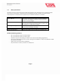
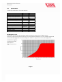
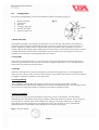
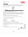
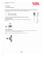
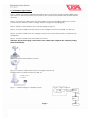
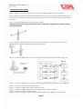
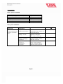
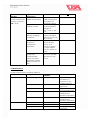
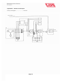
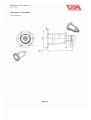
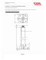
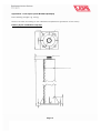
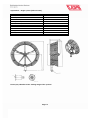
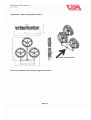
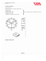
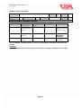
UGA Wind-Turbine
WT 200 and WT 200/3
User Manual
Heidenheimer Str. 80 - 82, D-89542 Herbrechtingen
P.O. Box 12 61, D-89539 Herbrechtingen
Phone +49 7324 9696-0, Fax +49 7324 9696-96
[email protected], www.uga.eu
08/2010
UGA SYSTEM-TECHNIK GmbH & Co. KG
Building Technical Systems
Index:
UGA Wind-Turbine WT 200 and WT 200/3
User manual
Content
Page
1.0
2.0
3.0
4.0
5.0
5.1
5.2
6.0
7.0
8.0
1
2
3-4
4-5
6
7
8
9-10
10
11-19
Safety precautions
Specifications
Configurations
Field survey
Installation
Installation single-turbine
Installation triple-turbine
Operation
Maintenance
Appendices
1.0
Safety precautions
All safety aspects concerning the WT 200 wind turbines are tabulated in the following table
with focus on electronic, mechanical and installation pitfalls. Installers should read the
manual prior to commence the project to put double attention on safeties.
Safety focus
Rotor / Blades
Conditions
During the testing of the system or field installation
do not put your fingers or body to touch the rotor
blades to avoid danger.
Generator
During the testing of the system or field installation,
need to short circuit the power cable to strain the
rotor/blades on high wind rotating
System grounding
Ground the system from the power control unit to
avoid current leakage damage
Circuit breaker
Need circuit breaker to avoid system short circuit
Cable-specification
Follow VDE cable spec to select the suitable one
Tabelle 1 Table of safety focus
WT 200 Installation guidelines:
-
Do not install the system on windy days
Do not install the system on rainy days
Install the system according to the IEC rules and local building regulations
If you hear abnormal sounds or noice during the installation, call your qualified installer
for trouble shootings
Follow this user manual for installation
Pay attention to safety concerns in all aspects
Page 1
2.0
Specifications
General specifications of WT 200 turbines
Article number
WT 200/1
WT 200/3
Yes
Yes
Shrouded design
1
3
Number of PM generators
200
600
Rated power (W)
12
12
Voltage output (Vdc)
0.68
0.68
Rotor diameter (m)
5
3x5
Number of blades/set
2.5
2,5
Start-up wind speed (m/s)
12.0
12.0
Rated wind speed (m/s)
20.0
20.0
Cut out wind speed (m/s)
Simplex
Triplex
Frame support
912x330x1026
2052x330x2100
Dimension (mm)
11
43
Weight (kg)
Passive
Passive
Yawing control
Electromagnetic
Electromagnetic
Brake
Table 2 General specification of WT 200 wind turbines
WT 200 power curve
The power curve of the WT 200 wind turbine has been outlined in the figure below.
When the wind speed exceeds 20 m/s the wind turbine will detect an over-voltage signal and
automatically triggered the electromagnetic brake to suppress the rotor spinning speed.
Performance graph
Performance (kW)
Wind speed
Fig. 1 Power curve
Page 2
3.0
Configurations
The system configuration of the wind turbine WT 200 is consisting of (fig. 2):
1.
2.
3.
4.
5.
6.
Blade assembly
Generator
Nacelle
Yawing / Slip ring
Shroud assembly
Power control unit
Fig. 2
5
1
2 u. 3
6
4
1. Blade assembly
The blade assembly is consisting of five blades on a wheel disc. Wind drives the blades to
transform wind energy into mechanical torque, which in consequence, forces the rotor to
rotate against the stator inside the generator. Since the blades are required to work in a
hostile, high wind blowing, high rotating speed environment, therefore it is important to select
suitable material to meet these requirements. We put head cone In this group to prevent
pollution and corrosive material getting into the wheel.
2. Generator
The funtion of the generator is to convert rotor`s mechanical torque into electrical power.
Inside the generator the key central rotor rotates against shell stator to unit. The WT 200 uses
direct drive synchronous PM generator.
3. Nacelle
Inside the nacelle an IC circuit is designed to fit behind the generator, to rectify generator
inducted AC current to DC current. It also detects overcurrent and sends a short circuit signal
to trigger magnetic constrains to the generator.
4. Yawing/Slip ring
The combined yawing/slip ring design ensures that the whole wind turbine unit will
automatically face the wind to minimize the head-on wind blowing stress. The slip ring ensures
the system to rotate 360° freely to transmit power without wiring the joint.
5. Shroud assembly
The shroud is composed of three Nylon shell covers, three oval-shaped, central-hollow
aluminium bars, assembled in place by stainless steel bolts and lock washers. The function of
the shroud is to collect wind and maximize the energy conversion efficiency (> 50%) by
increasing the wind speed at the central rotor plane. The function of the oval-shaped
aluminium bar is to streamline the passing air in a steady state (fig. 3)
Fig. 3 – Shroud-design
Page 3
6. Power control unit
The function of the power control unit is to regulate the generated voltage (various from
0-25VDc) to a constant level to charge a battery bank. The manual brake design of the
power control unit will restrain the turbine to work in a hostile environment. (fig. 4)
Fig. 4 – Power control unit
4.0
Field survey
The performance of the windturbine is strongly depending on the optimal location!
Step 1: Appraise wind prospect of a specified site
Check the wind atlas survey data (the wind energy distribution at 10m, at 30m and at 50m
height) to find out the average wind speed near the chosen site. If the average wind speed
at the spot exceeds 4m/s in our opinion the site is ok to install wind turbines. However the
actual survey on wind velocity and wind blow direction has to be carried out before the
installation.
Step 2: Measure the wind speed and direction at the specific site
The surveyor installs an anemometer at a specific site with requirements on height:
1. Open area - erect a 6m tower from the ground
2. Tall building - erect a 3m tower on the roof
On sampling rate:
1. Daily survey
2. Weekly survey
3. Monthly survey
1 sec./sample
10 min./sample
10 min./sample
Step 3: Survey topography of the site and determine the tower height
The general rule to find the right height is to detect the tallest object in the vicinity (the
circular area of 170m diameter) of the tower. Add 10m to the height of this object to get the
ideal tower height (fig. 5).
Ht = H0 + 10 m
Ht
Ht = Ideal tower height
H0 = Height of the tallest object within 170m vicinity of the tower.
H0
Fig. 5
Page 4
Step 4: How to estimate the average wind velocity of a specific height (Table 3)
Please find out the average wind speed in a height of 10m or 30m in the wind energy
distribution data wind of Wind Atlas. Then use the follwing formula to calculate the average
wind speed at a certain height (Vt):
Vt = V10 * (Ht/H10)*(log-1α)
Vt :
V10 :
Ht :
H10 :
α:
Wind speed at the tower height
Wind speed extract from Wind Atlas database at 10m level
Specific tower height
10 m height
Wind shear effect
Table 3 –The factors of the wind shear effect.
α
0.1
0.2
0.3
0.4
0.5
0.6
Field description
Calm lake surface
Short grass or low bush area
Distance with trees, hills or buildings
Neighbouring to trees or buidlings
Very close to trees or buildings
Surrounded by trees or buidlings
Page 5
5.0 Installation
1. Verticality of the tower
There is an important relationship between the verticality of the tower and the mobility of the
wind turbine yawing mechanism. The more inclined angle on verticality , the stronger wind
blowing force to to overcome the deviated centroid weight (fig. 6).
Fx = Fz * tan θ
θ:
Fx :
Fz :
Verticality inclined angle
System centroid weight
Deviated centroid weight
2. The effectiveness of wind blowing direction to system axis (fig. 7)
Single wind turbine:
The single wind turbine can rotate 360° to follow the wind blowing
direction.
Triple wind turbine:
To get maximum energy conversion efficiency this system needs to be installed with its axis
perpendicular to the major wind blowing direction.
Fig 7. The effectiveness of wind blowing direction to system axis
Page 6
5.1 Installation single-turbine
Step 1: Follow the tower installation requirements to erect tower and pre-install cables inside
the tower. Fix the bottom plate to the tower to the concrete foundation with specified bolts
and nuts.
Step 2: Connect the cables from the wind turbine to the per-installed cables in the tower
(colour match: Red for positive voltage, black for negative voltage)(fig. 8)
Step 3: Tread on wind turbine to the tower jointing set (fig. 9).
Step 4: Connect cables from the tower to the charger control unit. (Modell: CC-200-13)
Step 5: Connect cables from the charger control unit to the battery bank to complete the
installation.
Fig. 8 –Connect cables from wind turbine to tower
Attention: Please fix the plug connections of the cables (the weight of the cabled is pulling
them downwards)!
Fig. 9 –Connect wind turbine to tower
Fig. 10 – Connect cables from tower to charger control unit
Simplex tower; Charger control CC-200-12;
Charger control
CC-200-12
Fig. 11 – Cable routing of a simplex system
WT 200 Charger control unit
Battery
14,5 Vdc 100 Ah
0-25 Vdc
12 Vdc
Inverter
300W
L
Page 7
N
Load
5.3 Installation triple-turbine
Step 1: Tread-on tri-tube to triple-tower and pre-install the cables inside the tower.
Step 2: Follow the tower installation requirements to erect tower and pre-install cables inside
the tower. Fix the bottom plate to the tower to the concrete foundation with specified bolts
and nuts.
Step 3: Connect cables from wind turbine to tower
Attention: Please fix the plug connections of the cables (the weight of the cabled is pulling
them downwards)!
Step 4: Tread-on wind turbine unit to the tower jointing set. Fix the rotor blades that no
electricity is generated during the installation! (fig. 13)
Step 5: Connect cables from tower to charger control unit (Modell: CC-200-12) (fig. 14)
Fig. 15
Charger control
CC-200-12
Charger control
WT 200
0-25 Vdc
Battery
12 Vdc
14,5 Vdc
Charger control
WT 200
0-25 Vdc
WT 200
14,5 Vdc
Inverter
Charger control
L
0-25 Vdc
14,5 Vdc
N
Load
Step 6: Connect cables from charger control to battery bank to complete the installation
Fig. 12 –Tread-on tri-tube to the triple tower
Fig. 13 – Connect cables from wind turbine to tower
Fig. 14 – Connect cables from tower to charger control unit CC-200-12;
Fig. 15 – Cable routing of a triple system
Triple system: 3 x charger control; battery (not included in the delivery); inverter; user
Page 8
6.0 Operation
Before system installation
Check item
Funtionality of a generators output cable
Functionality of a charger control
Voltage level of battery
Funtionality of a inverter
Power consumption of a load
Table 4 System check before installation
Tool
Digital multi-meter
12 Vdc power supply
Digital multi-meter
12 Vdc power supply
12 Vdc power supply
After system installation
System link
without ATS
Wind turbine >
power control unit >
battery > inverter >
load
System turn-on
procedures
Step 1: Check all
cable connections
Step 2: Check
charge control
Step 3: Check
battery charging
conditions
Step 4: Turn on
inverter to
commence
operation
Pass/fail criteria
If ok fill in: ok
Make sure that all cable
connections are correct on
electrical polarity
Make sure charge control
regulates voltage at
Vcc = 14,5 +/- 0,5 Vdc
Make sure that battery
voltage is higher than 10
Vdc: Vb > 10 Vdc
Make sure Wi>1.5*Wi (the
power of an inverter is
always 1,5 times higher
than the power of load)
ok
Page 9
ok
ok
ok
System link
with ATS
Wind turbine >
power control unit >
battery > inverter >
ATS > load
System turn-on
procedures
Step 1: Check all
cable connections
Pass/fail criteria
If ok fill in: ok
Make sure that all
cable connections
are correct on
electrical polarity
Make sure charge
control regulates
voltage at
Vcc = 14,5 +/- 0,5
Vdc
Make sure that
battery voltage is
higher than 10 Vdc:
Vb > 10 Vdc
Make sure
Wi>1.5*Wi (the
power of an
inverter is always
1,5 times higher
than the power of
load)
Make sure if
Vb < Vdc, the ATS
will switch to city
power
ok
Areas of focus
Rotor bearing
Maintenance
schedule
Semi-anual
Rotor shaft
Annual
Bolts
Annual
Blades
Annual
Shroud
Annual
Slip ring
Brake
Charger control
Semi-annual
Annual
Annual
Step 2: Check
charge control
Step 3: Check
battery charging
conditions
Step 4: Turn on
inverter to
commence
operation
Step 5: Check if the
system will
automatically
switch to power
grid when battery
ampere hours run
low
Table 5 System check after installation
ok
ok
ok
ok
7.0 Maintenance
WT 200 maintenance schedule (table 6)
Field
Key parts
Mechanics
Electronics
Page 10
Check bearing
conditions on
corrosion or any
possible disortion
Corrosion
inspection
Tightness and
corrosion inspection
Fatigue, surface
damage and
disortion inspections
UV aging, surface
damage and
disortion inspections
Resistivity inspection
Brake inspection
Charging
inspection
8.0 Appendices
Appendix 1
Appendix 2
Appendix 3
Appendix 4
Appendix 5
Appendix 6
Electric circuit layout
Tower jointer
Tower single system WT 200/1
Tower triple system WT 200/3
Single system (without tower)
Triple system (without tower)
Page 11
Appendix 1 –Electric circuit layout
From power grid… … … … … … … .. to load
> Power grid
Load
Page 12
Appendix 2 - Tower jointer
Raw drawing
Page 13
Appendix 3 - Tower single system WT 200/1 (Example)
Raw drawing, weight e.g. 85 kg,
Please use bolts according to the calculated requirements (producer of the tower)
Delivery by the installation company!
Page 14
Appendix 4 - Tower triple system WT 200/3 (Example)
Raw drawing, weight e.g. 145 kg,
Please use bolts according to the calculated requirements (producer of the tower)
Delivery by the installation company!
Page 15
Appendix 5 –Single system (without tower)
Technical specifications 200 W wind turbine
Rated power
Rated speed rotor
Rated wind speed
Starting wind speed
Cut out wind speed
Max. wind resistibility
Rotor no.
Rotor diameter
Voltage
Brake type
Weight
200 W
2.250 RPM
12 m/s
2,5 m/s
20 m/s
60 m/s
5
0,68 m
12 V dc
Electronic
11 kg
Please pay attention to the slewing range of the system!
Page 16
Appendix 6 –Triple system (without tower)
Major wind direction
Please pay attention to the slewing range of the system!
Page 17
Product specification
Model: WT 200
Product description: WT 200/1 Single system
Quantity: N/A
Oder no.: N/A
Customer name: N/A
Installation place: N/A
Installation date: N/A
Installation company/contractor: N/A
WT 200/1 Single system
Page 18
To be completed by the installation company
WT 200/1 Single wind turbine
Product
WT 200/1 Single wind turbine
Rated
200 Output Voltage
12
power
W
Vac
System assembly by installation company!
No.
Model
Dimension
WT
200
912x330x1026
Order
no.
Weight
Key
component
WT 200
shrouded wind
turbine
Assembly
Code
WT 200/1
Quantity
Major function
1
Use 1 set WT
200/1 to form a
single model
2
Single frame
support
ES 1
0
3
Power control
system
LS 200/1
1
Delivered by
installation
company
1 charger
controller
1
Your installation company gladly consults you regarding the utilization of the produced
energy.
Examples:
You can produce warm water, built up your own power supply or feed power to the grid.
Page 19
N/A
11kg