1
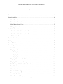
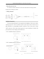
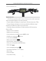
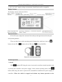
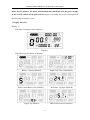
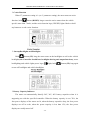
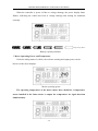
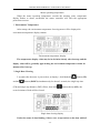
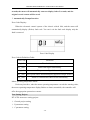
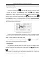
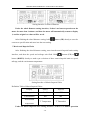
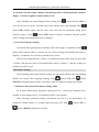
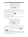
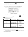
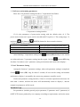
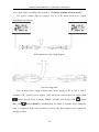
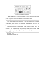
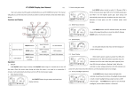
用户手册
User Manual
KT-LCD3 eBike Special Meter
WWW.SZKTDZ.COM
ELECTRIC BICYCLE METER KT—LCD3 Product User Manual
Contents
Preface……………………………………………………………………………..………. 4
Outlook and Size…………………………………………………………………………... 4
MeterDimension……………………………………………………………………… 4
Button Box Dimension……………………………………………………………….. 4
Main Material and Color………………………………………………….………...... 5
Wiring Schematic……………………………………………………………….……. 5
Installation Instruction……………………………………………………………….…….. 5
Φ 31.8 handlebar diameters install icon………………………………………..….… 5
Φ 22.2 handlebar diameters install icon……………………………………….….…. 5
Physical installation icon............................................................................................. 6
Function Overview……………………………………………………………………..….. 6
Display Content…………………………………………………………………….….…... 7
Button Definition…………………………………………………………………….….…. 7
Normal Operation………………………………………………………………………...... 7
On/Off…………………………………………………………………………........... 7
Display Interface………………………………………………………….….……..... 8
Display 1………………………………………………………………..……...... 8
Display 2……………………………………………………………………...... 9
Display 3……………………………………………………………..……….... 10
Display of Turned on Handlebar……………………………………………………. 11
Display of Power-assist Startup…………………………………………………….. 11
PAS Ratio (or Handlebar) Gear Switch……………………………….……………. 12
Push Function…………………………………………………………..…………… 12
Cruise Function…………………………………………………………………...… 13
Turn On/Off Backlight…………………………………………………….………... 13
Battery Capacity Indicator…………………………………………..…………….… 13
Motor Power and Temperature ................................................................................... 14
-1-
ELECTRIC BICYCLE METER KT—LCD3 Product User Manual
Environment Temperature…………………………………………………………... 15
Single Data Clearing……………………………………………………………….... 15
Automatic Prompt Interface……………………………………………………..….. 16
Error Code Display…………………………………………………….…........ 16
Motor Operating Temperature Alarm……………………………………......... 16
User Project Setting……………………………………………………………………..... 16
General Project Setting…………………………………………………………………… 17
Maximum Trip Speed………………………………………………………….......... 17
Wheel Diameter…………………………………………………………………..…. 17
Metric and Imperial Units…………………………………………………………... 18
Exit General Project Setting……………………………………………………….... 19
P Parameter Setting……………………………………………………………….…….... 19
P1 Motor Characteristic Parameter Setting Mode ...................................................... 19
P2 Wheel Speed Pulse Signal Setting Mode .............................................................. 20
P3 Power Assist Control Mode .................................................................................. 21
P4 Handlebar Startup Mode ....................................................................................... 21
P5 Power Monitoring Mode ....................................................................................... 22
Exit P Parameter Setting ............................................................................................. 23
C Parameter Setting ............................................................................................................ 23
C1 Power Assist Sensor and Parameter Selection Mode ........................................... 23
C2 Motor Phase Classification Coding Mode ............................................................ 24
C3 Power Assist Ratio Gear Initialization Mode........................................................ 25
C4 Handlebar Function Setting Mode ........................................................................ 25
C5 Controller Maximum Current Adjustment Mode ................................................. 26
C6 Backlight Brightness Adjustment Mode ............................................................... 27
C7 Cruise Function Setting Mode .............................................................................. 28
C8 Motor Operating Temperature Display Mode ...................................................... 28
C9 Power-on Password Setting Mode ........................................................................ 29
C10 Automatic Restore Default Setting Mode ........................................................... 30
C11 Attribute Selection Mode .................................................................................... 31
-2-
ELECTRIC BICYCLE METER KT—LCD3 Product User Manual
C12 Controller Minimum Voltage Adjustment Mode ............................................... 32
C13 ABS brakes of the controller and parameters of anti-charge control...................34
C14 Power-assist tuning parameters............................................................................35
Exit C Parameter Setting............................................................................................. 35
Parameter Copy .................................................................................................................. 35
User Setting Note ............................................................................................................... 37
Version Information……………………………………………………………………… 37
-3-
ELECTRIC BICYCLE METER KT—LCD3 Product User Manual
Preface
The illustrated manual will help you understand and be familiar with the meter
function, guiding you on how to operate the meter, how to set the project parameters, how
to achieve the best match of the three as motor, controller and meter to improve electronic
control performance of the electric motor. This manual covers installation, operation,
parameter setting of the meter and how to use it properly, which help you resolve the
problems appeared in practical use.
Outlook and Size
○ Meter Dimension
Meter Dimension
Dual Bracket Mounting Dimension
○ Button Box Dimension
-4-
ELECTRIC BICYCLE METER KT—LCD3 Product User Manual
○ Main Material and Color
PC material is mainly used for KT-LCD3 meter and button box housing, and the
housing color is dark gray or white.
○ Wiring Schematic
Installation Instruction
The meter body and button box are mounted on the handlebars of the electric vehicle,
adjusting perspective. In the case that the vehicle is power off, the meter connectors are in
plug connection to corresponding controller connectors. Turn on the power, electric
vehicle and meter will be under normal operation, the meter installation is finished. The
protection film on meter display panel should be torn.
○ Φ 31.8 handlebar diameters install icon
○ Φ 22.2 handlebar diameters install icon
-5-
ELECTRIC BICYCLE METER KT—LCD3 Product User Manual
○ Physical installation icon
Function Overview
KT-LCD3 meter provide you with a variety of functions such as vehicle controls and
vehicle status digitized displays to meet the trip demands.
◇ Trip time display (with displays of a single trip time (TM) and total trip time (TTM));
◇ Trip speed display (with displays of real-time speed (Km/H or MPH) and a single
maximum speed (MXS) and a single average speed (AVS));
◇ Trip distance display (with displays of a single trip distance (DST) and total trip
distance (ODO));
◇ Display of turned on handlebar;
◇ Display of power-assist startup;
◇ Power assistant ratio (or handlebar) gear (ASSIST) switch;
◇ 6Km/H power assistant push (
) function;
◇ Cruise function (CRUISE);
◇ Battery capacity indicator (
);
◇ Real-time battery voltage (VOL) display;
◇ Motor power and temperature (MOTOR) display;
◇ Brake display (
);
◇ Turn on backlighting and lights (
);
◇ Environment temperature (℃ or ℉) display;
◇ Data clearing;
◇ Fault code display;
◇ User parameter setting
-6-
ELECTRIC BICYCLE METER KT—LCD3 Product User Manual
◇ 24V, 36V, 48V supply voltage can automatic identification and be compatible
Display Content
The display content is shown as follow.
Button Definition
KT-LCD3 meter adopts the structural form with part design between the main part
and operating buttons.
There are three keys on the operating panel of button box, which are icons of
button (alt text UP),
button (alt text SW) and
(alt text DOWN).
Button Box and Operating Panel
Normal Operation
○ On/Off
Hold
button (SW) long, the meter is powered on and into normal operation, and
it provides the controller with power supply. Under normal operating status, hold
button (SW) long, the meter is powered off, meanwhile to shutdown the power supply of
controllers. When the vehicle is stopped and without any button operation on the
-7-
ELECTRIC BICYCLE METER KT—LCD3 Product User Manual
meter for five minutes, the meter will automatically shut down, and the power supply
of the electric vehicle will be powered off. In power off mode, the power consumption of
the meter and controller is zero.
○ Display Interface
Display 1:
The meter is startup to enter display 1.
Display 1
The followings are shown on display 1.
Battery Capacity Indicator
Single Trip Time (TM) Display
Power Assist Ratio Gear (ASSIST)
Real-time Trip Speed (Km/H)
Single Trip Distance
6Km/H Power Assist Function
-8-
ELECTRIC BICYCLE METER KT—LCD3 Product User Manual
Motor Operation Power
Environment Temperature
Backlights and Headlights Status
Brake Status
Cruise Function (CRUISE)
Motor Running Temperature
Display 2:
In display 1, hold
button (SW) shortly to enter display 2.
Display 2
The followings are shown on display 2:
Total Trip Time (TTM)
Total Trip Distance (ODO)
-9-
ELECTRIC BICYCLE METER KT—LCD3 Product User Manual
Single Average Speed (AVS)
Motor Operating Temperature
In the riding mode after 5 seconds, display 2 automatically returns to display 1.
In display 1, the original motor power is replaced by motor running temperature as is
shown in Figure.
Display 3:
In display 2, hold
button (SW) shortly to enter display 3.
Display 3
The followings are shown on display 3.
Single Maximum Speed (MXS)
Real-time Voltage (VOL)
In the riding mode after 5 seconds, single maximum speed will automatically
return to real-time trip speed (Km/H) as shown in the icon.
- 10 -
ELECTRIC BICYCLE METER KT—LCD3 Product User Manual
In display 3, hold
button (SW) shortly again to enter display 1.
In each display interface, if you hold
button (SW) long, the meter will be
powered-off together with that of the controller.
○ Display of turned on handlebar
Rotate the handlebar under normal operating of the meter, the display interface shows
the sign of turned-on handlebar, see the Figure below. The sign will be off automatically
after about five seconds.
○ Display of power-assist startup
The meter is driving with power-assist under normal operating conditions, the display
interface flashes the power-assist startup sign (ASSIST) as shown in the figure. The sign
will be off automatically after about five seconds.
- 11 -
ELECTRIC BICYCLE METER KT—LCD3 Product User Manual
○ PAS Ratio (or Handlebar) Gear Switch
Under normal operation, hold
button (UP) or
button (DOWN) to
switch the power assist ratio (or handlebar) gear (ASSIST), changing motor output power.
Switching range is 1-5 gear (this can also be configured according to the customer
requirements), gear 1 is for the lowest power, and gear 5 is for the highest power.
At every startup, the meter will automatically restore gear (this can also be
configured as required by users) when it was at last shut down. When the power
assist ratio is gear 0 zero, there’s no power assist function.
○ Power Assistant Push Function
Users can use 6Km/H power assist function when pushing vehicles. Hold
button (DOWN), the meter assist function logo ( ) flashes, the vehicle drives at the speed
of no more than 6Km/h. Release
button (DOWN), the assist function will be
revoked.
- 12 -
ELECTRIC BICYCLE METER KT—LCD3 Product User Manual
○ Cruise Function
When C7 parameter setting is 1 (see C parameter setting), the meter turns on cruise
function, hold
button (DOWN) long to enter the cruise status when the vehicle
speed is more than 7 km/h, and the cruise function logo (CRUISE) lights. Brake or hold
any button to revoke cruise function.
○ Startup Backlights and Headlights
Hold
button (UP) long, the meter turns on the backlights as well as the vehicle
headlights (the Controller should have headlights driving and output functions), meter
backlighting and vehicle lights power logo (
) light, hold
button (UP) long again
to turn off backlights and vehicle headlights.
○ Battery Capacity Indicator
The meter can automatically identify 24V, 36V, 48V battery capacities when it is
supporting use with the specified controller. When the battery capacity is over 70%, the
four power displays of the meter are lit, when the battery capacities drop, the four power
displays are off in order, when the power capacity is less than 15%, the four power
displays are totally turned off.
- 13 -
ELECTRIC BICYCLE METER KT—LCD3 Product User Manual
When the controller is power off due to voltage shortage, the power display frame
flashes, indicating the vehicle has been in voltage shortage and waiting for shutdown
currently.
Voltage shortage flashes
Battery capacity indicator
○ Motor Operating Power and Temperature
Under the riding status of vehicle, the real time running and output power can be
known via the meter displays.
Motor operating power
The operating temperature of the motor shows there should be a temperature
sensor installed in the Inner motor to output the temperature for signal detection
simultaneously.
- 14 -
ELECTRIC BICYCLE METER KT—LCD3 Product User Manual
Motor operating temperature
When the motor operating temperature exceeds the warning value, temperature
display flashes to alarm, meanwhile the motor controller will offer the appropriate
protection to motor.
○ Environment Temperature
After startup, the environment temperature for using meter will be displayed in
environment temperature display column.
Environment temperature display
The temperature display value may be in deviation shortly after boot-up, and the
display value will be gradually approaching the environment temperature within 10
minutes after boot-up.
○ Single Data Clearing
5 seconds after the meter is powered on, at display 1, hold both the
and the
button (UP)
button (DOWN) simultaneously for about 2 seconds, the single trip time
(TM) and single trip distance (DST) flicker, then hold
button shortly (SW), the
record contents of both will be cleared.
Single data clearing display
Under the status of data flashing, if there were no operations on the data within 5
- 15 -
ELECTRIC BICYCLE METER KT—LCD3 Product User Manual
seconds, the meter will automatically return to display1 after 5 seconds, and the
original record content will be saved.
○ Automatically Prompt Interface
Error Code Display:
When the electronic control system of the electric vehicle fails, and the meter will
automatically display (flicker) fault code. You can’t exit the fault code display only the
fault is removed.
Error Code Display
Error Code & Definition Table:
Error Code
Definition
01_info
Throttle Abnormality
03_info
Motor Hall Signal Abnormality
04_info
Torque sensor Signal Abnormality
05_info
Axis speed sensor Abnormality(only applied to torque sensor )
06_info
Motor or controller has short circuit Abnormality
Motor operating temperature alarm:
Under any interface, when the motor operating temperature exceeds the warning value,
the motor operating temperature display flashes to alarm, meanwhile, the controller will
offer the appropriate protection to motor.
User Setting Project
KT-LCD3 meter user setting project:
◇ General project setting
◇ P parameter setting
◇ C parameter setting
- 16 -
ELECTRIC BICYCLE METER KT—LCD3 Product User Manual
General Project Setting
○ Maximum Trip Speed
Under power off status, hold
5 seconds after boot-up, hold
button long (SW), the meter is turned on. Within
button (UP) and
button (DOWN)
simultaneously for about 2 seconds, the first is to enter the maximum riding speed setting
interface, then the speed display column flashes. Hold
button shortly (UP) or
button (DOWN) in order to set the maximum riding speed value. The default maximum
riding speed value was 25Km/h. When the speed of the electric vehicle exceeds the set
value, the motor will be stopped driving.
Setting interface of maximum trip speed
Under the setting maximum riding speed interface, if there’s no button operation
on the meter for more than 1 minute, and then the meter will automatically return to
display 1, and the original set values will be saved.
After finishing the maximum riding speed setting, hold
button shortly (SW) to
save the current set values and enter into the next setting.
○ Wheel Diameter
After finishing the maximum riding speed setting, enter the wheel diameter setting
interface, and then the wheel diameter display column flashes. Hold
button (UP) or
button (DOWN) to choose the corresponding wheel diameter specification to a
selected vehicle. The selection range of wheel diameter specifications are 13 species such
as 6,8,10,12,14,16,18,20,22,24,26,700 c and 28 inches.
- 17 -
ELECTRIC BICYCLE METER KT—LCD3 Product User Manual
Setting Interface of Wheel Diameter
Under the wheel diameter setting interface, if there’s no button operation on the
meter for more than 1 minute, and then the meter will automatically return to display
1, and the original set values will be saved.
After finishing the wheel diameter setting, hold
button (SW) shortly to save the
current set specification and enter into the next setting.
○ Metric and Imperial Units
After finishing the wheel diameter setting, enter into the metric/imperial units setting
interface, and then the speed and mileage unit flash. Hold
button (UP) or
button (DOWN) shortly to make sync selection of three metric/imperial units as speed,
mileage, and the environment temperature.
Setting Interface of Metric/Imperial Units
Definition Table of Metric/Imperial Units:
Display
Metric
Imperial
Riding speed
Km/H
MPH
Total distance
Km
Mil
℃ Temperature
℉ Fahrenheit
Environment
temperature
Under the metric/imperial units setting interface, if there’s no button operation
- 18 -
ELECTRIC BICYCLE METER KT—LCD3 Product User Manual
on the meter for more than 1 minute, and then the meter will automatically return to
display 1, and the original set units will be saved.
After finishing the metric/imperial units setting, hold
button shortly (SW) to
save the current set values, and then speed and mileage units stop flashing. Hold
button (SW) shortly again, and the meter will enter into the maximum riding speed
interface again, or hold
button (SW) long for about 2 seconds to exit the general
project setting environment and return to display 1.
○ Exit General Project Setting
Among the three general project settings, after each setting is completed, if hold
button (SW) long for about 2 seconds, all can exit the setting environment and return to
display 1, meanwhile, the current set parameters are saved.
Under each setting interface, if there’s no button operation on the meter for more than
1 minute, and then the meter will automatically return to display 1, and the original set
parameters will be saved.
P Parameter Setting
After finishing metric/imperial unit settings, the speed and mileage units stop flashing.
Within one minute after stopping flashing, hold
button (UP) and
button
(DOWN) simultaneously for about 2 seconds to enter P parameter setting environment.
○ P1 Motor Characteristic Parameter Setting Mode
P1 is motor characteristic parameter setting mode. P1 = motor gear reduction ratio×
number of rotor magnet pieces, just rounding if there’s any decimal.
After entering P parameter setting environment, the first is to set P1parameter, P1
parameter column flashes. P1 setting ranges between1-255, hold
button (DOWN) shortly for selection.
- 19 -
button (UP) or
ELECTRIC BICYCLE METER KT—LCD3 Product User Manual
P1 parameter setting interface
Under P1 parameter setting interface, if there’s no button operation on the
meter for more than 1 minute, and then the meter will automatically return to display
1, and the original set parameter will be saved.
After finishing P1 parameter setting, hold
button shortly to save the current set
values and enter P2 parameter setting interface.
○ P2 Wheel Speed Pulse Signal Setting Mode
Enter P2 parameter setting interface after P1 parameter setting is finished, and P2
parameter column flashes.
P2 parameter setting interface
P2 is wheel speed pulse signal setting mode. If wheel generated 1 pulse signal by a
revolution, P2 should be set as1. If wheel generated 6 pulse signals by a revolution, P2
should be set as 6. If users didn’t configure the pulse signal system, and then P2 parameter
setting can be 0. The setting range of P2 should be between 0-6, hold
shortly or
button (UP)
button (DOWN) for selection.
Under P2 parameter setting interface, if there’s no button operation on the meter
for more than 1 minute, and then the meter will automatically return to display 1,
and the original set parameter will be saved.
- 20 -
ELECTRIC BICYCLE METER KT—LCD3 Product User Manual
After finishing P2 parameter setting, hold
button (SW) shortly to save the
current set values and enter P3 parameter setting interface.
Please Note:when P2 parameter is set to be 0, for the built-in clutch motor, there will
be the following defects, when the internal motor rotors stop or the internal rotor speed is
lower than the outer rotor speed, then the speed displayed on the meter is inaccurate!
○ P3 Power Assist Control Mode
Enter P3 parameter setting interface after P2 parameter setting is finished, and P3
parameter column flashes.
P3 parameter setting interface
P3 is for power assist control mode, when P3 parameter setting is1, power assist
control mode is gear 5 of "imitation torque control" mode, when P3 parameter setting is
0, power assist control mode is gear 5 of "speed control" mode. P3 parameter needs to be
determined according to the distributed function of the controller, its setting range is 0 or 1,
hold
button (UP) shortly or
button (DOWN) for selection. P3 parameter
setting method is the same to that of P2.
○ P4 Handlebar Startup Mode
Enter P4 parameter setting interface after P3 parameter setting is finished, P4
parameter column flashes.
- 21 -
ELECTRIC BICYCLE METER KT—LCD3 Product User Manual
P4 parameter setting interface
P4 is handlebar startup mode. When P4 setting is 1, indicating the handlebar is under
"non-zero startup" mode, namely, the handlebar can be effective only after startup the
foot power assist. When P4 setting is 0, indicating the handlebar is under "zero startup"
mode, the motor can be startup by the handlebar directly. P4 setting range is 0 or 1, hold
button (UP) or
button (DOWN) shortly for selection. P4 parameter setting
method is the same to that of P2.
○ P5 Power Monitoring Mode
Enter P5 parameter setting interface after P4 parameter setting is finished, P5
parameter column flashes.
P5 parameter setting interface
P5 is power monitoring mode, when P5 setting is 0, the power monitoring is the
"real-time voltage" mode. Namely, it is the method to determine the battery capacity
based on real-time battery voltage. When P5 equals to a specified parameter, the power
monitoring is the "smart power" mode (this parameter is determined by the battery
characteristics, ordinary 24V lithium is generally is 4-11, 36V lithium is between 5_15). P5
setting ranges from 0-40, hold
button (UP) or
button (DOWN) shortly for
selection. P 5 parameter setting method is the same to that of P2.
After finishing P5 parameter setting, hold
button (SW) shortly to save current
set the values, and then P5 parameter column stops flashing. Hold
button (SW)
shortly again, the meter re-enter P1 parameter setting interface. Or hold
button (SW)
long for about 2 seconds to exit P parameter setting environment and return to the display
- 22 -
ELECTRIC BICYCLE METER KT—LCD3 Product User Manual
1.
○ Exit P Parameter Setting
Among the five P parameter settings, when each parameter setting is completed, if
held
button (SW) long for about 2 seconds, all can exit the setting environment and
return to display 1, meanwhile, the current set parameters would be saved.
Under each parameter setting interface, if there’s no button operation on the meter for
more than 1 minute, and then the meter will automatically return to display 1, and the
original set parameters will be saved.
C Parameter Setting
After finishing P5 parameter setting, P5 parameter column stops flashing. Within 1
minute after stopping flashing, hold
button (UP) and
button (DOWN) for
about 2 seconds to enter C parameter setting environment.
○ C1 Power Assist Sensor and Parameter Select Mode
Set C1 parameter first after entering C parameter setting environment, C1 parameter
column flashes.
C1 parameter setting interface
C1 is power assist sensor and parameter select mode. Its definition is shown in
following table. C1 setting ranges between 0-7, hold
button (UP) or
button
(DOWN) for selection.
C1 parameter definition table:
KUNTENG power assist
sensors
Forward 5 Signal
C1
value
Start
Sensitivity
00
Standard
01
Lower
- 23 -
KUNTENG V12
power assist sensors
Reverse 6 Signal
C1
value
Start
Sensitivity
05
Standard
06
Lower
ELECTRIC BICYCLE METER KT—LCD3 Product User Manual
Forward 8 Signal
Forward 10 Signal
02
Lowest
07
Lowest
00
Higher
05
Higher
01
Standard
06
Standard
02
Lower
07
Lower
00
Highest
05
Highest
01
Higher
06
Higher
02
Standard
07
Standard
Reverse 10 Signal
Reverse 12 Signal
After finishing C1 parameter setting, hold
button (SW) shortly to save the
current set values and enter C2 parameter setting interface.
○ C2 Motor Phase Classification Coding Mode
Enter C2 parameter setting interface after C1 parameter setting is finished, C2
parameter column flashes.
C2 parameter setting interface
C2 is motor phase classification coding mode. It is served as identification parameter
of different phases of the motor when using sine wave drive and the default value is 0.
When C2 setting is 0, indicating that the used Quantum motor phase is an ordinary one.
When the setting is a certain value, indicating a particular motor phase is used. C2 setting
range is 0-7, hold
button (UP) or
button (DOWN) for selection.
After finishing C2 parameter setting, hold
button (SW) shortly to save the
current set values and enter C3 parameter setting interface.
- 24 -
ELECTRIC BICYCLE METER KT—LCD3 Product User Manual
○ C3 Power Assist Ratio Gear Initialization Mode
Enter C3 parameter setting interface after C2 parameter setting is finished, C3
parameter column flashes.
C3 parameter setting interface
C3 is initialization mode of power assist ratio gear. The setting range is 0-6 (gear),
hold
button (UP) or
button (DOWN) for selection. When C3 setting is 0, the
meter is switched on, and the power assist ratio is at gear 0. When the setting is 1, the
meter is powered on and the power assist ratio is at gear 1, and so on.
After finishing C3 parameter setting, hold
button (SW) shortly to save the
current set values and enter C4 parameter setting interface.
○ C4 Handlebar Function Setting Mode
Enter C4 parameter setting interface after C3 parameter setting is finished, C4
parameter column flashes.
C4 parameter setting interface
C4 is handlebar function setting mode. The setting range is 0-4, hold
(UP) or
button (DOWN) for selection.
C4 parameter definition table:
- 25 -
button
ELECTRIC BICYCLE METER KT—LCD3 Product User Manual
C4 value
0
Handlebar startup mode P4=0
Handlebar startup mode P4=1
zero startup handlebar
Non-zero startup handlebar
Zero startup, handlebar speed limit is
Before power assist, the handlebar speed limit is
6Km/h
6Km/h, after power assist, handlebar is full speed.
Zero startup, handlebar speed limit is
Non-zero startup, handlebar is specified speed
specified
limit.
Zero startup, Zero gear effectively
Retain
Handlebar gears is distinguished
Handlebar gears is distinguished according to the
according to the display meter.
display meter.
Retain
Retain
1
2
3
4
5
After finishing C4 parameter setting, hold
button (SW) shortly to save the
current set values and enter C5 parameter setting interface.
○ C5 Controller Maximum Current Adjustment Mode
Enter C5 parameter setting interface after C4 parameter setting is finished, C5
parameter column flashes.
C5 parameter setting interface
C5 is controller maximum operating current adjustment mode (tiny-adjustment of
limit current value). The default value is 10, setting range is 0-10, hold
or
button (UP)
button (DOWN) shortly for selection.
C5 parameter definition table:
C5 value
Maximum current value(A)
00
Undefined
- 26 -
ELECTRIC BICYCLE METER KT—LCD3 Product User Manual
01
Undefined
02
Undefined
03
Maximum current value÷2.00
04
Maximum current value÷1.50
05
Maximum current value÷1.33
06
Maximum current value÷1.25
07
Maximum current value÷1.20
08
Maximum current value÷1.15
09
Maximum current value÷1.10
10
Maximum current value
When C5 setting is 10, maximum current value is controller maximum operating
current value (ie, limit current value); when setting is 9, maximum current value divided by
1.10, when setting is 8, maximum current value divided by 1.15 and so on.
After finishing C5 parameter setting, hold
button (SW) shortly to save the
current set values and enter C6 parameter setting interface.
○ C6 Backlight Brightness Adjustment Mode
Enter C6 parameter setting interface after C5 parameter setting is finished, C6
parameter column flashes.
C6 parameter setting interface
C6 is the meter backlight brightness adjustment mode. The default value is 3, and
setting range is 1-5, hold
button (UP) or
selection.
C6 parameter definition table:
- 27 -
button (DOWN) shortly for
ELECTRIC BICYCLE METER KT—LCD3 Product User Manual
C6 value
Backlight brightness
1
Dimmest
2
Darker
3
Standard
4
Brighter
5
Brightest
After finishing C6 parameter setting, hold
button (SW) shortly to save the
current set values and enter C7 parameter setting interface.
○ C7 Cruise Function Setting Mode
Enter C7 parameter setting interface after C6 parameter setting is finished, C7
parameter column flashes.
C7 parameter setting interface
C7 is cruise function setting mode. The setting range is 0 or 1, hold
or
button (UP)
button (DOWN) shortly for selection.
C7 parameter definition table:
C7 value
Cruise function
0
Off
1
On
After finishing C7 parameter setting, hold
button (SW) shortly to save the
current set values and enter C8 parameter setting interface.
○ C8 Motor Operating Temperature Display Mode
Enter C8 parameter setting interface after C7 parameter setting is finished, C8
- 28 -
ELECTRIC BICYCLE METER KT—LCD3 Product User Manual
parameter column flashes.
C8 parameter setting interface
C8 is motor operating temperature display mode. The setting range is 0 or 1, hold
button (UP) or
button (DOWN) shortly for selection.
C8 parameter definition table:
C8 value
Motor operating temperature
0
Function off
1
Function on
Please Note:The motor operating temperature display requires installing temperature
sensor in the motor, output temperature detection signal simultaneously.
After finishing C8 parameter setting, hold
button (SW) shortly to save the
current set values and enter C9 parameter setting interface.
○ C9 Startup Password Setting Mode
Enter C9 parameter setting interface after C8 parameter setting is finished, C9
parameter column flashes.
C9 parameter setting interface
C9 is meter power-on password setting mode. The default value is 0, hold
- 29 -
ELECTRIC BICYCLE METER KT—LCD3 Product User Manual
button (UP) or
button (DOWN) shortly for selection.
C9 parameter definition table:
C9 value
Startup password setting
0
Function off
1
Function on
When C9 setting is 1, hold
button (SW) shortly, indicating that the password
function is startup, and then enter the password settings interface, three password setting
columns flash.
Password Setting Interface
The password setting is done sequentially from left to right, hold
button shortly
to confirm after each setting and enter next setting. Password setting range is 000-999, hold
button (UP) or
button (DOWN) shortly for selection.
Please note:If you forget your password, the parameters can only be copied (see
parameter copy) by data source meter prier to be decoded.
After finishing C9 parameter setting, hold
button (SW) shortly to save the
current set values and enter C10 parameter setting interface.
○ C10 Automatically Restore Default Setting Mode
Enter C10 parameter setting interface after C9 parameter setting is finished, C10
parameter column flashes.
- 30 -
ELECTRIC BICYCLE METER KT—LCD3 Product User Manual
C10 parameter setting interface
C10 is automatic restore default settings mode. The default is n, and the setting can be
n, or y, hold
button (UP) or
button (DOWN) shortly for selection.
C10 parameter definition table:
C10 value
Restore default setting
n
Function off
y
Function on
When the meter is needed to restore default setting, C10 selects y, hold
button
long for about 2 seconds, all parameters restore default settings and exit setting
environment, and then return to the display1.
C10 selects n, hold
button (SW) shortly to save the current set values and enter
C11 parameter setting interface.
○ C11 Attribute Selection Mode
Enter C11 parameter setting interface after C10 parameter setting is finished, C11
parameter column flashes.
C11 parameter setting interface
C11 is meter attribute selection mode. The setting range is 0-2, hold
- 31 -
button
ELECTRIC BICYCLE METER KT—LCD3 Product User Manual
(UP) or
button (DOWN) shortly for selection.
C11 parameter definition table:
C11
Meter Attribute
value
Meter uses LCD3 new version of communication protocol, it is compatible
0
LCD1 and LCD2.
Meter uses LCD1 and LCD2 old version communication protocol, it is not
1
compatible LCD3.
As data source for copying parameters, the meter transfers the new LD3
2
parameter to other meters.
C11 selects 2, hold
(SW) long for about 2 seconds to exit the setting
environment, and then the meter is served as data source for copying parameter (see
parameter copy), there’s source logo on display interface.
Data Source Display Interface
After finishing C11 parameter setting, hold
button (SW) shortly to save the
current set values and enter C12 parameter setting interface.
○ C12 Controller Minimum Voltage Adjustment Mode
Enter C12 parameter setting interface after C11 parameter setting is finished, C12
parameter column flashes.
- 32 -
ELECTRIC BICYCLE METER KT—LCD3 Product User Manual
C12 parameter setting interface
C12 is controller minimum operating voltage adjustment mode (tiny adjustment of
voltage shortage). The default value is 4, and the setting range is 0-7, hold
(UP) or
button
button (DOWN) shortly for selection.
C12 parameter definition table:
Minimum Voltage(V)
C12 value
24V Controller
36VController
48VController
0
Default value-2V
Default value-2V
Default value-2V
Default
Default
1
Default value-1.5V
value-1.5V
value-1.5V
Default value-1V
Default value-1V
Default
Default
value-0.5V
value-0.5V
Default value
Default value
30V
40V
Default
Default
value+0.5V
value+0.5V
Default value+1V
Default value+1V
Default
Default
value+1.5V
value+1.5V
2
Default value-1V
3
Default value-0.5V
4
5
Default value 20V
Default value+0.5V
6
Default value+1V
7
Default value+1.5V
C12 default value is 4, namely, controller minimum operating voltage (voltage
shortage value); when setting is 5, the default value plus 0.5V, when setting is 4, the
default value minus 0.5Vand so on.
- 33 -
ELECTRIC BICYCLE METER KT—LCD3 Product User Manual
After finishing C12 parameter setting, hold
button (SW) shortly to save the
current set values and enter C13 parameter setting interface.
○
C13 ABS brakes of the controller and parameters of anti-charge control
Enter into C13 parameter setting interface, C13 parameter bar flashes.
C13 parameter setting interface
C13 is ABS brakes of the controller and parameters of anti-charge control. The
default value is 0 with the setting range between 0-5, press
(UP) button or
(DOWN) button to make selection.
C13 parameter definition table:
C13 Value
ABS braking strength
0
None
Energy recovery efficiency
None
Best energy recovery
1
Class 1 braking strength
efficiency
General energy recovery
2
Class2 braking strength
efficiency
Weaker energy recovery
3
Class 3 braking strength
efficiency
Poor energy recovery
4
Class4 braking strength
efficiency
Bad energy recovery
5
Class5 braking strength
efficiency
The recommended value of C13 is 1; other values need to be chosen with caution for
use.
Be sure to note: the higher is the braking intensity level, and the braking strength
will be greater, the greater damage to the motor shaft accordingly.
After finishing the parameter setting of C13, press
C14 parameter setting interface.
- 34 -
(SW) button for short to enter
ELECTRIC BICYCLE METER KT—LCD3 Product User Manual
○ C14 Power-assist tuning parameters
Enter into C14 parameter setting interface, C14 parameter bar flashes.
C14 parameter setting interface
C14 is the parameters of power-assist tuning with the default value of 2. The
power-assist is between1-4 gear, and it is invalid until P3 equals to 1. The setting range 1-3,
and press
(UP) button or
(DOWN) button for short to make selection.
C14 parameter definition table:
C14 Value
1
2
3
Assist strength of intelligent pedal motor
Weak assist strength of motor
General assist strength of motor
Stronger assist strength of motor
After finishing C14 parameter setting, hold
button (SW) shortly to save current
set values and enter C1 parameter setting interface again. Or hold
button (SW) long
for about 2 seconds to exit C parameter setting environment and return to the display 1.
○ Exit C Parameter Setting
Among the fourteen C parameter settings, when each parameter setting is completed,
if held
button (SW) long for about 2 seconds, all can exit the setting environment
and return to display 1, meanwhile, the current set parameters would be saved.
Under each parameter setting interface, if there’s no button operation on the meter for
more than 1 minute, and then the meter will automatically return to display 1, and the
original set parameters will be saved.
Parameter Copy
Set parameters (include general project parameter, P parameter and C parameter) of
all KT-LCD3 meter produced by our company according to requirements, and set the meter
- 35 -
ELECTRIC BICYCLE METER KT—LCD3 Product User Manual
to be a data source according to the method of "C11meter attribute selection mode".
Use special wiring cables to properly wire to LCD3 meter needs to be copied
according to the diagram.
Meter parameter copy wiring diagram
Special wiring cable
Turn on meter power supply of data source. Power supply of 48V or 36V or 24V is
available (VB + positive power supply). After wiring the meter needs to be copied, hold
button long till meter is startup. Within 5 seconds after startup, hold
(UP) and
button
button (DOWN) simultaneously for about 2 seconds, meter parameter
copy is completed. If the copy operation is correct, the meter subject to be copied will
display as follow.
- 36 -
ELECTRIC BICYCLE METER KT—LCD3 Product User Manual
Interface of finishing parameter copy
Please note: Both C9 power-on password and C11 meter attributes can’t be copied.
Besides, LCD3 meter can only copy parameter of the same meter model.
User Setting Note
After entering the user setting environment, if there’s no button operation on the data
for more than 1 minute, the meter will automatically return to display1, and the new set
parameters won’t be saved.
The factory parameter set value and the default value of the meter can be set
according to user requirements, the meter parameter can be restored by using "C10
automatically restore factory setting mode" approach when adjusting it.
Version Information
KT_LCD3_V2.0
Released on October 20, 2014
- 37 -