1
FINE TUNE
CONTROL
SWITCH
INDICATOR
MAX
MIN
8. 8.
3
STORE
(EXECUTE)
EFF1
2 MIN
MAX
4
1/2
GROUP.BANK
MIN
U :USER P :PRESET . :BOTH
COMP
MAX 1
DIST
GROUP
COMPARE
EQ
EFF2
EDIT
EXIT
EFF3
UTILITY
PAGE
ADVANCED GUITAR EFFECTS PROCESSOR
DLY
REV
–
MAX
MIN
MAX
INCREASE
TOTAL
TYPE
MIN
+
r
Supe
PRESENCE
OUTPUT
CONTROL
PEDAL
CONTROL
SWITCH
BLINK
(DLY:TAP)
DECREASE
–(TAP/HOLD)
CONTROL
PEDAL
BANK
USER
FUNCTION
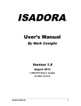
Operation Manual
®
Thank you for selecting the ZOOM SUPER PLAYER 8080 (hereafter simply called the "8080").
The 8080 is a sophisticated multi-effect device with the following features and functions:
• 47 types of high-quality single effects produced by two new-generation Zoom
DSP ZFx-2 chips. Up to 10 effects can be combined for simultaneous use, with
flexible patching arrangements. Virtually unlimited possibilities let you create
your ultimate guitar sound.
• Large internal memory holds 150 superb preset patches programmed by topnotch professionals, plus 50 user- definable patches.
• Many effects simulate the sound of famous vintage effects that are hard to find
nowadays. Faithful recreation even includes the operation 'feel'.
• Seamless patch change lets you activate a new patch while the old patch still
reverberates, ensuring smooth transitions.
• Dedicated analog circuitry for various distortion effects. Built-in amp simulator
maintains dynamic guitar sound also during line recording and headphone
monitoring.
• Patches can include external effect on/off setting and external amp channel
selection.
• Four data entry knobs and an array of large foot switches allow easy control and
adjustment with an analog touch. Even musicians who have so far only used
compact effects will instantly feel at home.
• Integrated auto-chromatic guitar tuning function with tuning meter allows quick
and precise tuning of instruments on stage.
• Three real-time control circuits and two control pedals can be used for pedal
wah, pedal pitch shifter and any other effect parameter or level setting. Separate
control switches allow step-by-step adjustment.
Please take the time to read this manual carefully, in order to get the most out of your 8080 and to
ensure optimum performance and reliability.
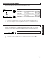
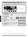
1■
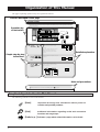
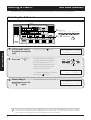
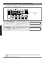
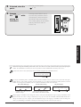
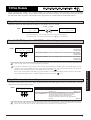
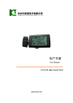
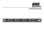
Organization of This Manual
The pages explaining operation steps are organized as follows.
Function described on this page
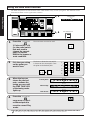
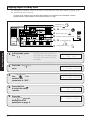
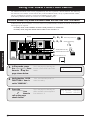
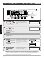
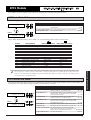
Selecting a patch
In Play mode, you can select from among 100 patches (one PRESET group A-C with 50 patches and the USER
group with 50 patches).
8080 Basic Operation
Operation key
or foot switch
Beacon
FINE TUNE
CONTROL
SWITCH
INDICATOR
MAX
MIN
MAX 1
MIN
MAX
3
2 MIN
MAX
4
1/2
GROUP.BANK
U :USER P :PRESET . :BOTH
COMP
EFF1
STORE
(EXECUTE)
DIST
GROUP
COMPARE
EQ
EFF2
EDIT
EXIT
EFF3
UTILITY
PAGE
ADVANCED GUITAR EFFECTS PROCESSOR
DLY
REV
–
MIN
MAX
INCREASE
TOTAL
TYPE
MIN
+
Super
PRESENCE
OUTPUT
CONTROL
SWITCH
CONTROL
PEDAL
–(TAP/HOLD)
GROUP key
Use the
to
select the group.
Simple step-by-step
instructions
BANK
/
switches
Use the
to select a bank from
0-9.
Foot switches
3
/
switches
BANK
3
1
GROUP
COMPARE
GROUP key
2 BANK
DECREASE
USER
FUNCTION
BANK
CONTROL
PEDAL
1
BLINK
(DLY:TAP)
Use the
1-5
to select the patch
number.
U: Patches from USER group only
P: Patches from PRESET group
only
U. or P.: Patches from both groups
With each push of the key, the
setting cycles through the above
modes.
Foot switches 1-5
USER
PRESET
BOTH
BOTH
Detailed explanation
In this condition, the patch is not yet
selected.
P0
P9
The indicator of the foot switch
lights up and the respective patch
becomes active.
P9
Hints and precautions
✎
For information on how to switch between the PRESET groups A-C,
NO
see page 35.
11
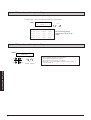
Graphical Symbols Used in This Manual
The following symbols are used in this manual.
✎
[Note]
Important warnings and information about points to
consider and possible problems
[Hint]
Additional information regarding useful and convenient
functions and usage steps
N
HINT
[Refer to p. ] Indicates a page where related information can be found.
■2
USAGE AND SAFETY PRECAUTIONS
Safety Precautions
In this manual, symbols are used to highlight warnings and
cautions for you to read so that accidents can be prevented.
The meanings of these symbols are as follows:
This symbol indicates explanations
about extremely dangerous matters. If
Warning users ignore this symbol and handle
the device the wrong way, serious
injury or death could result.
Caution
This symbol indicates explanations
about dangerous matters. If users
ignore this symbol and handle the
device the wrong way, bodily injury
and damage to the equipment could
result.
Please observe the following safety tips and precautions
to ensure hazard-free use of the 8080.
• Power requirements
Warning
The 8080 is powered by the supplied AC adapter . To
prevent malfunction and safety hazards, Do not use any
other kind of AC adapter.
Usage Precautions
• Electrical interference
For safety considerations, the 8080 has been designed to
provide maximum protection against the emission of
electromagnetic radiation from inside the device, and from
external interference.However, equipment that is very
susceptible to interference or that emits powerful
electromagnetic waves should not be placed near the 8080, as
the possibility of interference cannot be ruled out entirely.
Whatever the type of digital control device, the 8080 included,
electromagnetic damage can cause malfunctioning, and can
corrupt or destroy data. Since this is an ever-present danger,
thorough care should be taken to minimize the risk of damage.
• Cleaning
Use a soft, dry cloth to clean the 8080. If necessary, slightly
moisten the cloth. Do not use abrasive cleanser, wax, or
solvents (such as paint thinner or cleaning alcohol), since these
may dull the finish or damage the surface.
Please keep this manual in a convenient place for future
reference.
When using the 8080 in an area with a different line
voltage, please consult your local ZOOM distributor
about acquiring a proper AC adapter.
• Environment
Caution
Avoid using your 8080 in environments where it will be
exposed to:
• Extreme temperature
• High humidity or moisture
• Excessive dust or sand
• Excessive vibration or shock
• Handling
Caution
Since the 8080 is a precision electronic device, avoid
applying excessive force to the switches and buttons.
Also take care not to drop the unit, and do not subject it
to shock or excessive pressure.
• Alterations
Caution
Caution
Never open the case of the 8080 or attempt to modify the
product in any way since this can result in damage to the
unit.
• Connecting cables and input and
output jacks
You should always turn off the power to the 8080 and all
other equipment before connecting or disconnecting any
cables. Also make sure to disconnect all cables and the
AC adapter before moving the 8080.
3■
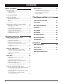
Contents
Basic Operation
Names of Parts • • • • • • • • • • • • • • • • • • • • • • • • • • • • • • • • • • • • • • • • • • • • • • • • • • • • • • • • 6
Top Panel View • • • • • • • • • • • • • • • • • • • • • • • • • • • • • • • • • • • • • • • • • • • • • • • • • • • • • • 6
Rear Panel View • • • • • • • • • • • • • • • • • • • • • • • • • • • • • • • • • • • • • • • • • • • • • • • • • • • • • 6
Connection Examples
•••••••••••••••••••••••••••••••••••••••••••
7
Outline of the 8080 • • • • • • • • • • • • • • • • • • • • • • • • • • • • • • • • • • • • • • • • • • • • • • • • •
Effect module configuration • • • • • • • • • • • • • • • • • • • • • • • • • • • • • • • • • • •
Patches • • • • • • • • • • • • • • • • • • • • • • • • • • • • • • • • • • • • • • • • • • • • • • • • • • • • • • • • • • • • • • • • • • • •
Modes • • • • • • • • • • • • • • • • • • • • • • • • • • • • • • • • • • • • • • • • • • • • • • • • • • • • • • • • • • • • • • • • • • • • •
Preparations • • • • • • • • • • • • • • • • • • • • • • • • • • • • • • • • • • • • • • • • • • • • • • • • • • • • • • • • • • • •
8
8
8
9
9
Trying Out a Patch (Play Mode Operation) • • • • • • • •
Indications in Play mode • • • • • • • • • • • • • • • • • • • • • • • • • • • • • • • • • • • • • •
Selecting a patch • • • • • • • • • • • • • • • • • • • • • • • • • • • • • • • • • • • • • • • • • • • • • • • • • • •
Effect Module On/Off Switching • • • • • • • • • • • • • • • • • • • • • • • • •
Using the bypass/mute function • • • • • • • • • • • • • • • • • • • • • • • • • • •
Using the Auto tuner function • • • • • • • • • • • • • • • • • • • • • • • • • • • • • •
Calibrating the tuner reference pitch • • • • • • • • • • • • • • • • • • • •
Adjusting the patch level • • • • • • • • • • • • • • • • • • • • • • • • • • • • • • • • • • • • • •
10
10
11
12
13
14
15
16
Other Functions • • • • • • • • • • • • • • • • • • • • • • • • • • • • • • • • • • • • • • • • • • • • • • • • • • • •
Controlling an external effect device • • • • • • • • • • • • • • • • • • • •
Controlling an external amplifier • • • • • • • • • • • • • • • • • • • • • • • • •
Returning the 8080 to the factory
default condition • • • • • • • • • • • • • • • • • • • • • • • • • • • • • • • • • • • • • • • • • • • • • • • • •
Editing a Patch (Edit Mode Operation) • • • • • • • • • • • • • • • • • • •
Activating the Edit mode • • • • • • • • • • • • • • • • • • • • • • • • • • • • • • • • • • • • • •
Indications in Edit mode • • • • • • • • • • • • • • • • • • • • • • • • • • • • • • • • • • • • • • •
Switching modules on and off • • • • • • • • • • • • • • • • • • • • • • • • • • • • • •
Changing the parameter settings • • • • • • • • • • • • • • • • • • • • • • • • • • •
Comparing an edited patch with its original
condition • • • • • • • • • • • • • • • • • • • • • • • • • • • • • • • • • • • • • • • • • • • • • • • • • • • • • • • • • • • •
Storing an edited patch • • • • • • • • • • • • • • • • • • • • • • • • • • • • • • • • • • • • • • • • •
18
18
19
20
21
22
23
Using the RTM Function • • • • • • • • • • • • • • • • • • • • • • • • • • • • • • • • • • • • •
Using the CONTROL pedals for RTM • • • • • • • • • • • • • • • •
Using the CONTROL switches for RTM • • • • • • • • • • • • •
Tapping input of delay time • • • • • • • • • • • • • • • • • • • • • • • • • • • • • • • • • •
Delay hold • • • • • • • • • • • • • • • • • • • • • • • • • • • • • • • • • • • • • • • • • • • • • • • • • • • • • • • • • • • • •
24
24
26
28
30
Utility Mode • • • • • • • • • • • • • • • • • • • • • • • • • • • • • • • • • • • • • • • • • • • • • • • • • • • • • • • • • • • •
Switching between Utility mode and
Play mode • • • • • • • • • • • • • • • • • • • • • • • • • • • • • • • • • • • • • • • • • • • • • • • • • • • • • • • • • • •
Amp simulator settings: pages 1, 2 • • • • • • • • • • • • • • • • • • • • • • •
USER FUNCTION switch settings: page 3 • • • • • • • • •
MIDI settings: pages 4 - 6 • • • • • • • • • • • • • • • • • • • • • • • • • • • • • • • • • • • •
Foot switch settings: pages 7, 8 • • • • • • • • • • • • • • • • • • • • • • • • • • • •
Switching PRESET groups A/B/C: page 9 • • • • • • • • • • •
32
Using the USER FUNCTION Switch • • • • • • • • • • • • • • • •
To switch between Play mode and Manual mode
with the USER FUNCTION switch • • • • • • • • • • • • • • • • • • •
Using the USER FUNCTION switch to call up
a bank or patch • • • • • • • • • • • • • • • • • • • • • • • • • • • • • • • • • • • • • • • • • • • • • • • • • • • • • •
Using the USER FUNCTION switch to
select PRESET A/B/C • • • • • • • • • • • • • • • • • • • • • • • • • • • • • • • • • • • • • • •
36
■4
32
33
33
34
35
35
36
38
40
44
Effect Types and Parameters
Effect Modules of the 8080
••••••••••••••••••••••••••••••••
46
CMP (Compressor) Module
•••••••••••••••••••••••••••••••
47
••••••••••••••••••••••••••••••••••••••••••••••••••••••••••
48
EFF1 Module
DIST (Distortion) Module
EQ Module
••••••••••••••••••••••••••••••••••••
50
••••••••••••••••••••••••••••••••••••••••••••••••••••••••••••••
54
EFF2 Module
••••••••••••••••••••••••••••••••••••••••••••••••••••••••••
55
EFF3 Module
••••••••••••••••••••••••••••••••••••••••••••••••••••••••••
58
DLY (Delay) Module
Advanced Operation
41
41
42
•••••••••••••••••••••••••••••••••••••••••••••
REV (Reverb) Module
TOTAL Module
60
••••••••••••••••••••••••••••••••••••••••••
62
••••••••••••••••••••••••••••••••••••••••••••••••••••••
63
APPENDIX
MIDI Implementation
Specifications
••••••••••••••••••••••••••••••••••••••••••
66
•••••••••••••••••••••••••••••••••••••••••••••••••••••••
67
Troubleshooting
••••••••••••••••••••••••••••••••••••••••••••••••••••
MIDI Implementation Chart
68
Basic Operation
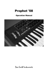
Names of Parts
Top Panel View
•••••••••••••••••••••••••••••••••••••••••••••••••••••••••••••••••••••••••••••••••••••••••••••••••••••••••••••••••••••••••••••••••••••••••••••••••••••••••••••
•••••••••••••••••••••••••••••••••••••••••••••••••••••••••••••••••••••••••••••••••••••••••••••••••••••••••••••••••••••••••••••••••••••••••••••••••••••••••••••••••••••••
Rear Panel View
••••••••••••••••••••••••••••••••••••••••••••••••••••••••••••••••••••••••••••••••••••••••••••••••••••••••••••••••••••••••••••••••••••••••••••••••••••••••••••••••••••
6
6
6
Connection Examples
7
Outline of the 8080
8
••••••••••••••••••••••••••••••••••••••••••••••••••••••••••••••••••••••••••••••••••••••••••••••••••••••••••••••••••••••••••
•••••••••••••••••••••••••••••••••••••••••••••••••••••••••••••••••••••••••••••••••••••••••••••••••••••••••••••••••••••••••••••••••••••••••••
Effect module configuration
•••••••••••••••••••••••••••••••••••••••••••••••••••••••••••••••••••••••••••••••••••••••••••••••••••••••••••••••••••••••
8
••••••••••••••••••••••••••••••••••••••••••••••••••••••••••••••••••••••••••••••••••••••••••••••••••••••••••••••••••••••••••••••••••••••••••••••••••••••••••••••••••••••••••••••••••••••••••••••••••••••
8
•••••••••••••••••••••••••••••••••••••••••••••••••••••••••••••••••••••••••••••••••••••••••••••••••••••••••••••••••••••••••••••••••••••••••••••••••••••••••••••••••••••••••••••••••••••••••••••••••••••••••••
9
Patches
Modes
Preparations
•••••••••••••••••••••••••••••••••••••••••••••••••••••••••••••••••••••••••••••••••••••••••••••••••••••••••••••••••••••••••••••••••••••••••••••••••••••••••••••••••••••••••••••••••••
Trying Out a Patch (Play Mode Operation)
Indications in Play mode
••••••••••••••••••••••••••••••
9
10
••••••••••••••••••••••••••••••••••••••••••••••••••••••••••••••••••••••••••••••••••••••••••••••••••••••••••••••••••••••••••••••
10
•••••••••••••••••••••••••••••••••••••••••••••••••••••••••••••••••••••••••••••••••••••••••••••••••••••••••••••••••••••••••••••••••••••••••••••••••••••••••••
11
Selecting a patch
Effect Module On/Off Switching
•••••••••••••••••••••••••••••••••••••••••••••••••••••••••••••••••••••••••••••••••••••••••••••••••
Using the bypass/mute function
Using the Auto tuner function
•••••••••••••••••••••••••••••••••••••••••••••••••••••••••••••••••••••••••••••••••••••••••••••••
13
••••••••••••••••••••••••••••••••••••••••••••••••••••••••••••••••••••••••••••••••••••••••••••••••••••••••••
14
Calibrating the tuner reference pitch
Adjusting the patch level
12
•••••••••••••••••••••••••••••••••••••••••••••••••••••••••••••••••••••••••••••••
15
••••••••••••••••••••••••••••••••••••••••••••••••••••••••••••••••••••••••••••••••••••••••••••••••••••••••••••••••••••••••••••••
16
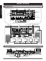
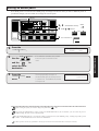
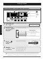
Names of Parts
Top Panel View
Tuning meter
Basic Operation
Enlarged Operation Panel View
Data entry knobs 1-4
Display
FINE TUNE
CONTROL
SWITCH
INDICATOR
MAX
MAX 1
MIN
U0
Beacon
3
2 MIN
MAX
CONTROL SWITCH
INDICATOR
4
1/2
GROUP. BANK
MIN
U :USER P :PRESET . :BOTH
COMP
Effect keys
EFF1
DIST
STORE
(EXECUTE)
EQ
GROUP
COMPARE
EFF2
EDIT
EXIT
EFF3
DLY
REV
UTILITY
PAGE
–
MIN
MAX
TOTAL
TYPE
MIN
+
r
Supe
ADVANCED GUITAR EFFECTS PROCESSOR
MAX
PRESENCE
OUTPUT control
BLINK
(DLY:TAP)
OUTPUT
PRESENCE control
TYPE -/+ keys
UTILITY/PAGE key
STORE/EXECUTE key
EDIT/EXIT key
GROUP/COMPARE key
BANK
/
CONTROL switches (INCREASE/DECREASE)
TAP/HOLD INDICATOR
switches
USER FUNCTION switch
FINE
FINE TUNE
TUNE
CONTROL
CONTROL
SWITCH
SWITCH
INDICATOR
INDICATOR
MAX
MAX
MIN
MIN
U0
3
3
EFF1
EFF1
STORE
STORE
(EXECUTE)
(EXECUTE)
2
2 MIN
MIN
MAX
MAX
4
4
1/2
1/2
BANK
/ TUNER
GROUP.BANK
MIN
MIN
:PRESET :BOTH
UU:USER
:USER PP :PRESET. :BOTH
COMP
COMP
MAX
1
MAX 1
DIST
DIST
EQ
EQ
GROUP
GROUP
COMPARE
COMPARE
EFF2
EFF2
EDIT
EDIT
EXIT
EXIT
EFF3
EFF3
UTILITY
UTILITY
PAGE
PAGE
ADVANCED
ADVANCED GUITAR
GUITAR EFFECTS
EFFECTS PROCESSOR
PROCESSOR
DLY
DLY
REV
REV
–
–
TYPE
TYPE
MIN
MIN
MAX
MAX
MIN
MIN
+
+
r
Supe
INCREASE
PRESENCE
PRESENCE
CONTROL
PEDAL
CONTROL
SWITCH
BLINK
BLINK
(DLY:TAP)
(DLY:TAP)
OUTPUT
OUTPUT
DECREASE
–(TAP/HOLD)
USER
FUNCTION
BANK
CONTROL
PEDAL
MAX
MAX
TOTAL
TOTAL
CONTROL pedal 1
CONTROL pedal 2
Foot switches 1-5
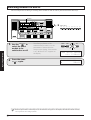
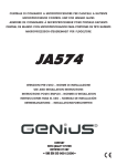
Rear Panel View
INPUT GAIN SELECT switch
MIDI OUT jack
L/MONO/R OUTPUT jacks
PHONES jack
POWER switch
SERIAL NO.
INPUT GAIN INPUT
H M L
DC9V1.0A
EXTERNAL DIST
SEND
RETURN
+4dB
–20dB
PHONES
OUTPUT
R
L/MONO
+4dB
–20dB
POWER
MIDI
Super
INPUT jack
EXTERNAL DIST SEND jack
EXTERNAL DIST RETURN jack
■6
OUT
EXT
CTRL OUT
AC ADAPTOR jack
EXTERNAL CONTROL jack
OUTPUT LEVEL GAIN switch
EXTERNAL DIST RETURN GAIN switch
MODEL 8080 ZOOM CORPORATION
MADE IN JAPAN/FABRIQUE AU JAPON
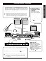
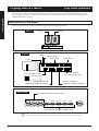
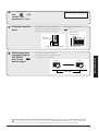
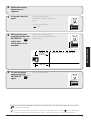
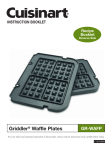
Connection Examples
When using only one guitar amplifier, connect the L/MONO OUTPUT jack of the
8080 to the input of the guitar amplifier. In this case, the L and R signals of stereo
effects will be combined in the output.
When using two guitar amplifiers, connect the L and R OUTPUT jacks of the
8080 to the inputs of the guitar amplifiers.
✎
Connection example 3:
external guitar amplifier
connection
When wishing to control
channel switching of a guitar
amplifier using the foot switches
of the 8080, connect the
EXTERNAL CONTROL jack
of the 8080 with the foot switch
jack of the guitar amplifier,
using either a stereo or mono
cable (
p. 42).
Set the OUTPUT LEVEL GAIN switch to the position which matches the input
NOsensitivity of the connected equipment. For connection to a guitar amplifier, the
"-20 dB" position will normally be best, whereas professional effect devices and
mixing consoles will work better with the "+4 dB" setting.
FOOT SWITCH INPUT
R OUTPUT
L OUTPUT
L/MONO OUTPUT
INPUT
EXTERNAL CONTROL
PHONES
SERIAL NO.
INPUT GAIN INPUT
H M L
DC9V1.0A
EXTERNAL DIST
SEND
RETURN
+4dB
–20dB
PHONES
OUTPUT
R
L/MONO
+4dB
–20dB
POWER
IN
OUT
MODEL 8080 ZOOM CORPORATION
MADE IN JAPAN/FABRIQUE AU JAPON
Super
EXTERNAL
DIST SEND
MIDI
EXT
CTRL OUT
MIDI OUT
EXTERNAL
DIST RETURN
OUT
MIDI cable
MIDI IN
Connection example 2: external effect/preamplifier connection
When wishing to control the on/off condition of an external distortion effect
or preamplifier or similar, connect the effect device in the EXTERNAL
DIST SEND and EXTERNAL DIST RETURN loop (
p. 41).
Connection example 4:
MIDI connection
When wishing to control the
programs of a MIDI-compatible
external distortion effect or
preamplifier or similar, connect the
MIDI jack of the device to the
MIDI OUT jack of the 8080, using
a MIDI cable(
p.34).
✎
Set the EXTERNAL DIST RETURN GAIN switch to the position which matches
the output level of the connected equipment. For use with a compact
NOeffect device, the "-20 dB" position will normally be best, whereas
professional effect devices and guitar preamplifiers will work better with
the "+4 dB" setting.
7■
8080 Basic Operation
Connection example 1: instrument/guitar amplifier connection
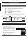
Outline of the 8080
This section explains what the 8080 is and what it can do. You will also find explanations of some important
terms here.
Basic Operation
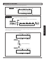
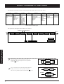
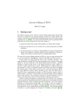
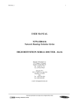
Effect module configuration
The 8080 is a multi-effect device made up of eight different effect modules (effect blocks). Each effect module
acts like a single compact effect. The following modules are available:
• COMP ••••••••••••• Compressor effects for processing the sound level
• EFF1 ••••••••••••••••• Equalizer effects and wah/modulation effects with strong characteristics.
Can be inserted before or after the DIST module.
• DIST •••••••••••••••••• Analog distortion effects
• EQ ••••••••••••••••••••••• Basic equalizer effects
• EFF2 ••••••••••••••••• Modulation-type effects for changing pitch and creating special effects
• EFF3 ••••••••••••••••• Standard modulation-type effects such as flanger and chorus
• DLY •••••••••••••••••••• Stereo delay effects
• REV •••••••••••••••••••• Reverberation effects
Almost all effect modules contain several variations of an effect (effect types), out of which the user can select
the most suitable one. The illustration below shows the signal flow in the 8080 and the effect types for the
various effect modules.
EXTERNAL DIST SEND/RETURN
L/R
OUTPUT
INPUT
COMP
EFF 1
Compressor 1
1-Band Parametric EQ
"Vintage" Compressor2 Pedal-Wah
Limiter
"Vintage" Auto-Wah1
Auto-Wah2
"Vintage" Phaser1
"Vintage" Vibe
Octaver
✎
DIST
EQ
EFF2
EFF3
External DIST
Pedal Pitch Shifter
3-Band Equalizer
Acoustic
2-voice Pitch Shifter
Rhythm
Pitch Shifter-Delay
2-voice Harmonized Pitch Shifter
"Vintage" OverDrive
Pitch Bender
Tube OverDrive
Slow Attack
Blues OverDrive
Metallic
"Vintage" DIST P
"Vintage" DIST M
"Vintage" Fuzz B
"Vintage" Fuzz-F
LeadDriver
Metal Distortion
ZNR
Guitar Amp Simulator
DLY
Flanger1
"Vintage" Flanger2
Phaser2
Chorus1
"Vintage" Chorus2
Vibrato
Step
Tremolo/Pan
REV
Normal Delay
Reverb Hall
Twin Delay
Reverb Room
Hold Delay
PingPong Delay
"Vintage" Analog Delay
TOTAL
PATCH LEVEL
The EFF1 module can be inserted before or after the DIST module.
NOThe EFF2 and EFF3 modules can be connected in series or parallel.
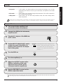
Patches
Internal settings of the 8080 are called patches which can be stored in memory and called up at any time. A patch
consists of the parameter settings for the various effect modules, plus information about the patch level, control
pedal and control switch settings, EFF1 routing, EFF2/EFF3 connection type, etc. The section enclosed in a
dotted line in the above illustration is a patch.
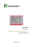
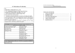
The 8080 divides patches into four groups: one USER group for
patches that can be changed by the user and three PRESET
groups (A-C) for patches that have been programmed at the
factory. Each group contains 50 patches, resulting in a total of
200 patches. The 8080 allows simultaneous use of one group
from the PRESET A-C groups and one patch from the USER
group.
Groups that can be used together
PRESET group A
BANK
Patch No.
USER group
BANK
Patch No.
0
9
1
1
1
2
2
2
3
3
3
4
4
4
5
5
5
0
9
HINT
■8
You can use the USER FUNCTION switch on the top panel
to select PRESET groups A-C (
p. 40).
2
2
2
3
3
3
4
4
4
5
5
5
PRESET group B
BANK
Patch No.
0
Within a group, patches are divided into "banks" of five patches
each. Every group has ten such banks (numbered 0- 9).
1
1
1
9
1
1
1
2
2
2
3
3
3
4
4
4
5
5
5
PRESET group C
BANK
Patch No.
0
9
1
1
1
2
2
2
3
3
3
4
4
4
5
5
5
Modes
The 8080 has the following three main operation modes:
••••••••••••
• Edit mode
••••••••••••
• Utility mode
•••••••••
In this mode, you select patches and use them for playing. You can also
temporarily turn effects off, tune your instrument, and perform some other
functions.
In this mode, you can edit (change) the parameters of the effect modules in
the currently selected patch.
In this mode, you can make amp simulator, MIDI, and other settings which
affect all patches.
Basic Operation
• Play mode
Besides the above mentioned main operation modes, the 8080 also has a manual mode for turning effect modules off and on
with the foot switches during a performance, and the so-called initialize mode for resetting the unit to the factory defaults.
HINT
Preparations
1
Turn power to the amplifier(s) off
and set the volume to minimum.
2
Connect the 8080 to the instrument,
amplifier(s) etc.
3
Plug the AC adapter of the 8080 into
an AC outlet.
4
Set the INPUT GAIN SELECT switch
on the rear panel of the 8080 to a
position which matches the output
level of the guitar.
5
Turn the 8080 on.
6
Turn the amplifier(s) on.
7
Adjust the OUTPUT control of the
8080 to a suitable position and
adjust the level controls on the
instrument and the amplifier(s).
8
INPUT GAIN
H M L
Recommended switch settings are as
follows. Guitars with single-coil pickups:
"H", guitars with hum-bucking type
pickups: "M", guitars with active type
pickups: "L".
POWER
OUTPUT
Use the PRESENCE control on the
8080 to adjust the timbre.
PRESENCE
✎
The settings of the OUTPUT and PRESENCE controls are not memorized.
NO
9■
Trying Out a Patch
(Play Mode Operation)
Basic Operation
The Play mode is the basic operation mode of the 8080, in which you select patches and use them while playing
your instrument. When the 8080 is turned on, the Play mode is automatically activated and patch number 1 of the
USER group/bank 0 is selected.
Indications in Play mode
In Play mode, the beacon, display, and effect keys show the following information.
Beacon
Bank
Group
U0
GROUP.BANK
U :USER
Display
P :PRESET . :BOTH
Bank
Patch number
Patch name
Group
Patch level
BLANK =USER
=PRESET A
=PRESET B
=PRESET C
Currently assigned
foot switch parameter
Amp simulator on/off
=Amp simulator on
=Amp simulator off
Currently assigned
CONTROL pedal 1 parameter
Effect keys
COMP
Currently assigned
CONTROL pedal 2 parameter
Currently active effect module (lit)
EFF1
DIST
EQ
EFF2
EFF3
DLY
REV
TOTAL
Currently inactive effect module (out)
✎
NOThe patch names and values shown in the illustration are an example. The actual display may differ.
■ 10
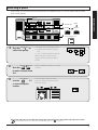
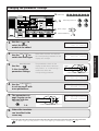
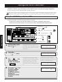
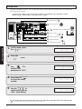
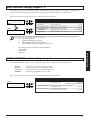
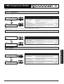
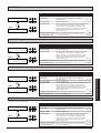
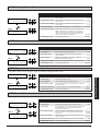
Selecting a patch
In Play mode, you can select from among 100 patches (one PRESET group A-C with 50 patches and the USER
group with 50 patches).
FINE TUNE
Basic Operation
Beacon
CONTROL
SWITCH
INDICATOR
MAX
MIN
MAX 1
3
2 MIN
MAX
4
1/2
GROUP.BANK
MIN
U :USER P :PRESET . :BOTH
COMP
EFF1
STORE
(EXECUTE)
DIST
GROUP
COMPARE
EQ
EFF2
EDIT
EXIT
EFF3
UTILITY
PAGE
ADVANCED GUITAR EFFECTS PROCESSOR
DLY
REV
–
MAX
MIN
MAX
INCREASE
TOTAL
TYPE
MIN
+
r
Supe
PRESENCE
OUTPUT
CONTROL
SWITCH
CONTROL
PEDAL
2 BANK
DECREASE
USER
FUNCTION
2
3
/
switches
BANK
3
1
GROUP
COMPARE
GROUP key
BLINK
(DLY:TAP)
–(TAP/HOLD)
BANK
CONTROL
PEDAL
1
GROUP key
Use the
to
select the group.
BANK
/
switches
Use the
to select a bank from
0-9.
Foot switches
Use the
1-5
to select the patch
number.
U: Patches from USER group only
P: Patches from PRESET group
only
U. or P.: Patches from both groups
With each push of the key, the
setting cycles through the above
modes.
Foot switches 1-5
USER
PRESET
BOTH
BOTH
In this condition, the patch is not yet
selected.
P0
P9
The indicator of the foot switch
lights up and the respective patch
becomes active.
P9
HINT
For information on how to switch between the PRESET groups A-C,
see page 35.
11 ■
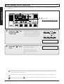
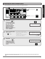
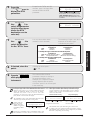
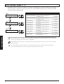
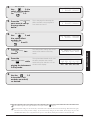
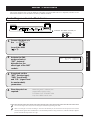
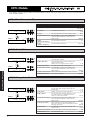
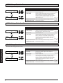
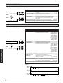
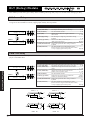
Effect Module On/Off Switching
Each patch of the 8080 is made up of several effect modules. Use the effect keys to switch the desired modules
on and off.
Basic Operation
Display
FINE TUNE
CONTROL
SWITCH
INDICATOR
MAX
MIN
MAX 1
3
2 MIN
MAX
4
1/2
MIN
COMP
STORE
(EXECUTE)
EFF1
DIST
GROUP
COMPARE
EQ
EFF2
EDIT
EXIT
EFF3
UTILITY
PAGE
ADVANCED GUITAR EFFECTS PROCESSOR
DLY
REV
–
MAX
MIN
MAX
INCREASE
TOTAL
TYPE
MIN
+
r
Supe
PRESENCE
OUTPUT
CONTROL
SWITCH
CONTROL
PEDAL
BLINK
(DLY:TAP)
1, 2
–(TAP/HOLD)
CONTROL
PEDAL
1
BANK
Press any Effect key that
is lit (except the
TOTAL key).
Effect keys
DECREASE
USER
FUNCTION
In Play mode, the keys of effect
modules that are currently active are
lit, and the keys of modules that are
currently inactive are out. Pressing a
lit effect key turns that module off.
COMP
EFF1
DIST
EQ
EFF2
EFF3
DLY
COMP
EFF1
DIST
EQ
COMP
EFF1
DIST
EQ
REV
01 8080LEAD LVL=100
AMP ¡VOL ™OFF ßHLD
2
Press the Effect key once
more.
The key lights up and the module
becomes active again.
01 8080LEAD LVL=100
é AMP ¡VOL ™OFF ßHLD
Other effect modules can be
switched off and on in the same
way.
✎
When an effect module is switched off or on, the indication " é " appears on the display. This indicates that the currently
NOselected patch has been changed (edited).
✎
The TOTAL module contains settings that are active for the entire patch. This module can therefore not be switched off.
NO
HINT
■ 12
Unless you store the new setting (
p. 23), any changes that you have made in the effect module on/off setting of a patch
will be lost when you select a different patch.
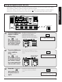
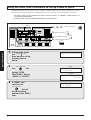
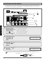
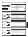
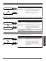
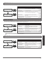
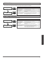
Using the bypass/mute function
Basic Operation
In the bypass condition, all effects of the 8080 are temporarily disabled, so that only the original sound is heard.
This is useful for example to check the overall sonic character of a patch.
In the mute condition, the effects of the 8080 as well as the original sound are disabled, so that the output is
muted. This is convenient for using the auto tuner function (
p. 14) without letting others hear the sound.
Display
Beacon
FINE TUNE
CONTROL
SWITCH
INDICATOR
MAX
MIN
MAX 1
3
2 MIN
MAX
4
1/2
MIN
COMP
STORE
(EXECUTE)
EFF1
DIST
GROUP
COMPARE
EQ
EFF2
EDIT
EXIT
EFF3
DLY
UTILITY
PAGE
ADVANCED GUITAR EFFECTS PROCESSOR
REV
–
MAX
MIN
MAX
INCREASE
TOTAL
TYPE
MIN
+
r
Supe
PRESENCE
OUTPUT
CONTROL
SWITCH
CONTROL
PEDAL
BLINK
(DLY:TAP)
DECREASE
–(TAP/HOLD)
BANK
CONTROL
PEDAL
USER
FUNCTION
Foot switches 1-5
1, 1', 2
1
To set the 8080 to the
bypass condition,
briefly press
Foot switches
All effects in the patch are now
bypassed and the original
instrument sound is heard. The
indicator of the foot switch flashes.
the
1-5
whose LED is lit (i.e.
the pedal switch that
was used to choose
the current patch).
-01 8080LEAD BYPASS
TUNER CALIB=440Hz
Release your foot straight away
1'
To set the 8080 to the
mute condition,
press
The output of the 8080 is cut off
and the indicator of the foot switch
flashes.
Foot switches
the
1-5
whose LED is lit (i.e.
the pedal switch that
was used to choose
the current patch) for
one second or more.
2
Press the
Foot switches
once more to turn
the patch back on
again.
Keep your foot more
tham one second
Normal Play mode can also be
restored by selecting a different
patch.
-01 8080LEAD
MUTE
TUNER CALIB=440Hz
U0
01 8080LEAD LVL=100
AMP ¡VOL ™OFF ßHLD
13 ■
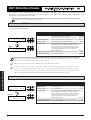
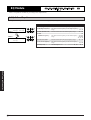
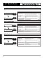
Using the Auto tuner function
The 8080 incorporates an auto-chromatic tuner which makes it easy to tune your guitar. This function can be
used when the 8080 is in the bypass/mute condition.
Basic Operation
2 Beacon
1, 3
Tuning meter
FINE TUNE
FINE TUNE
CONTROL
SWITCH
INDICATOR
MAX
MIN
MAX 1
MIN
MAX
3
2 MIN
MAX
4
1/2
COMP
STORE
(EXECUTE)
EFF1
DIST
GROUP
COMPARE
EQ
EFF2
EDIT
EXIT
EFF3
UTILITY
PAGE
ADVANCED GUITAR EFFECTS PROCESSOR
DLY
REV
–
MIN
MAX
INCREASE
TOTAL
MIN
+
TYPE
uper
PRESENCE
OUTPUT
CONTROL
SWITCH
CONTROL
PEDAL
BLINK
(DLY:TAP)
S
DECREASE
–(TAP/HOLD)
CONTROL
PEDAL
BANK
USER
FUNCTION
1, 4
1
Press the
Foot switches
Foot switches 1-5
The auto tuner can now be used.
1-5 whose LED is lit
(i.e. the pedal switch
that was used to
choose the current
patch) to set the
8080 to the bypass or
mute condition.
2
Pick the open string
on the guitar you
want to tune.
--
The beacon shows the note which
is closest to the current pitch. Tune
the guitar to the desired pitch.
-- C
3
4
When the beacon
shows the desired
note, continue the
tuning process until
the FINE TUNE LED
of the tuning meter
lights up.
Press the
C =
F=
A=
C #=
F #=
A #=
D=
G=
B=
D #=
G #=
E=
FINE TUNE
Correctly tuned
FINE TUNE
Pitch too high
FINE TUNE
Pitch too low
Foot switches
once more or select
a different patch to
revert to normal Play
mode.
✎
For tuning on stage or other situations where the sound should not be heard, use the mute function.
NO
■ 14
U0
Calibrating the tuner reference pitch
The reference pitch of the auto tuner in the 8080 can be adjusted as follows.
Beacon
Display
2
CONTROL
SWITCH
INDICATOR
MAX
MIN
MAX 1
3
2 MIN
MAX
EFF1
DIST
GROUP
COMPARE
EQ
EFF2
EDIT
EXIT
EFF3
UTILITY
PAGE
DLY
REV
–
ADVANCED GUITAR EFFECTS PROCESSOR
MAX
Data entry knob 2
4
1/2
MIN
COMP
STORE
(EXECUTE)
Basic Operation
FINE TUNE
MIN
MAX
MIN
INCREASE
MAX
TOTAL
TYPE
MIN
+
r
Supe
PRESENCE
OUTPUT
CONTROL
SWITCH
CONTROL
PEDAL
BLINK
(DLY:TAP)
DECREASE
–(TAP/HOLD)
BANK
CONTROL
PEDAL
USER
FUNCTION
1, 3
1
Press the
Foot switches
--
1-5 whose LED is lit
(i.e. the pedal switch
that was used to
choose the current
patch) to set the
8080 to the bypass or
mute condition.
2
Select the pitch with
Data entry knob
4.
3
Press the
01 8080LEAD BYPASS
TUNER CALIB=440Hz
The indication "TUNER CALIB"
appears on the display, along with
the current value.
Calibration is possible within the
range from 435 to 445 Hz.
01 8080LEAD BYPASS
TUNER CALIB=440Hz
Calibration
Foot switches
once more or select
a different patch to
revert to normal Play
mode.
✎
Foot switches 1-5
01 8080LEAD LVL=100
AMP ¡VOL ™OFF ßHLD
U0
The new reference pitch is stored automatically.
NO
15 ■
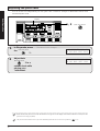
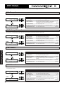
Adjusting the patch level
You can set the level independently for each patch. This is useful for example to differentiate between lead
sound and rhythm sound.
Basic Operation
Display
FINE TUNE
1, 2
CONTROL
SWITCH
INDICATOR
MAX
MIN
MAX 1
3
2 MIN
MAX
1/2
MIN
COMP
STORE
(EXECUTE)
EFF1
DIST
GROUP
COMPARE
EQ
EFF2
EDIT
EXIT
EFF3
UTILITY
PAGE
ADVANCED GUITAR EFFECTS PROCESSOR
DLY
REV
–
MAX
Data entry knob 2
4
MIN
MAX
INCREASE
TOTAL
TYPE
MIN
+
r
Supe
PRESENCE
OUTPUT
CONTROL
SWITCH
CONTROL
PEDAL
BLINK
(DLY:TAP)
MIN
MAX
DECREASE
–(TAP/HOLD)
CONTROL
PEDAL
BANK
1
In Play mode, move
the Data entry knob
2.
2
Adjust data
Data entry knob
2 to a
suitable level while
playing your
instrument.
USER
FUNCTION
The value of "LVL" changes.
01 8080LEAD LVL= 90
é AMP ¡VOL ™OFF ßHLD
01 8080LEAD LVL= 80
é AMP ¡VOL ™OFF ßHLD
✎
NO
✎
When the data entry knob 2 is moved, the indication "E" appears on the display. This indicates that the currently selected
patch has been changed (edited).
The patch level determines the level for each individual patch and can be stored as a parameter (
NO
■ 16
p. 23).
Advanced Operation
Editing a Patch (Edit Mode Operation)
•••••••••••••••••••••••••••••••
18
Activating the Edit mode •••••••••••••••••••••••••••••••••••••••••••••••••••••••••••••••••••••••••••• 18
Indications in Edit mode ••••••••••••••••••••••••••••••••••••••••••••••••••••••••••••••••••••••••••••• 19
Switching modules on and off ••••••••••••••••••••••••••••••••••••••••••••••••••••••••••••••• 20
Changing the parameter settings ••••••••••••••••••••••••••••••••••••••••••••••••••••••• 21
Comparing an edited patch with its original condition ••••••• 22
Storing an edited patch •••••••••••••••••••••••••••••••••••••••••••••••••••••••••••••••••••••••••••••• 23
Using the RTM Function
••••••••••••••••••••••••••••••••••••••••••••••••••••••••••••••
24
Using the CONTROL pedals for RTM ••••••••••••••••••••••••••••••••••••••••••••• 24
Using the CONTROL switches for RTM •••••••••••••••••••••••••••••••••••••••• 26
Tapping input of delay time ••••••••••••••••••••••••••••••••••••••••••••••••••••••••••••••••••••• 28
Delay hold •••••••••••••••••••••••••••••••••••••••••••••••••••••••••••••••••••••••••••••••••••••••••••••••••••••••••••••• 30
Utility Mode
•••••••••••••••••••••••••••••••••••••••••••••••••••••••••••••••••••••••••••••••••••••••••••••••••••••••
32
Switching between Utility mode and Play mode •••••••••••••••••••• 32
Amp simulator settings: pages 1, 2 •••••••••••••••••••••••••••••••••••••••••••••••••• 33
USER FUNCTION switch settings: page 3 ••••••••••••••••••••••••••••••••• 33
MIDI settings: pages 4 - 6 •••••••••••••••••••••••••••••••••••••••••••••••••••••••••••••••••••••••• 34
Foot switch settings: pages 7, 8 ••••••••••••••••••••••••••••••••••••••••••••••••••••••••• 35
Switching PRESET groups A/B/C: page 9 ••••••••••••••••••••••••••••••••• 35
Using the USER FUNCTION Switch ••••••••••••••••••••••••••••• 36
To switch between Play mode and Manual mode
with the USER FUNCTION switch •••••••••••••••••••••••••••••••••••••••••••••••••••• 36
Using the USER FUNCTION switch to call up
a bank or patch ••••••••••••••••••••••••••••••••••••••••••••••••••••••••••••••••••••••••••••••••••••••••••••••••• 38
Using the USER FUNCTION switch to select
PRESET A/B/C •••••••••••••••••••••••••••••••••••••••••••••••••••••••••••••••••••••••••••••••••••••••••••••••••• 40
Other Functions
••••••••••••••••••••••••••••••••••••••••••••••••••••••••••••••••••••••••••••••••••••••••
41
Controlling an external effect device •••••••••••••••••••••••••••••••••••••••••••••••• 41
Controlling an external amplifier ••••••••••••••••••••••••••••••••••••••••••••••••••••••••••• 42
Returning the 8080 to the factory default condition •••••••••••• 44
Editing a Patch
(Edit Mode Operation)
In the Edit mode, you can change the parameters of the various effects, to create your own sound effects.
Activating the Edit mode
Display
FINE TUNE
CONTROL
SWITCH
INDICATOR
MAX
MIN
MAX 1
3
2 MIN
MAX
4
1/2
MIN
COMP
STORE
(EXECUTE)
EFF1
DIST
GROUP
COMPARE
EQ
EFF2
EDIT
EXIT
EFF3
DLY
UTILITY
PAGE
REV
–
MIN
MAX
INCREASE
TOTAL
TYPE
MIN
+
r
Supe
ADVANCED GUITAR EFFECTS PROCESSOR
MAX
PRESENCE
OUTPUT
CONTROL
SWITCH
CONTROL
PEDAL
BLINK
(DLY:TAP)
2 Effect keys
COMP
EFF1
DIST
EQ
EFF2
EFF3
DLY
REV
DECREASE
–(TAP/HOLD)
CONTROL
PEDAL
USER
FUNCTION
BANK
2, 3
Advanced Operation
1
In Play mode, select
the patch you want to
edit.
2
Press the
EDIT/EXIT key
.
("Selecting a patch"
p. 11).
The 8080 enters the Edit mode.
Pressing any effect key will cause
the key indicator to flash. This
shows that effect module on/off
settings and parameters of this
effect can now be edited.
EDIT/EXIT key
01 8080LEAD LVL=100
AMP ¡VOL ™OFF ßHLD
COMP
TbOD
For a detailed explanation of editing
procedures,
see p. 21.
3
When editing is
terminated, press the
EDIT/EXIT key
again.
✎
EDIT
EXIT
EFF1
DIST
EQ
OD= 16 EQ=+10
LVL= 5 ZNR=off
The 8080 returns to the Play mode.
01 8080LEAD LVL=100
é AMP ¡VOL ™OFF ßHLD
You can select a patch from the USER or PRESET groups for editing. But because PRESET group patches are read-only,
NOyou cannot store an edited patch from a PRESET group in the same location. If you have edited a patch from a PRESET
group, a number in the USER group will be selected automatically as store destination.
■ 18
Indications in Edit mode
In Edit mode, display, and effect keys show the following information.
Display
Effect type
Parameter
Parameter
PIT PtL=+12 BIL=50
é
PtR=+24 BIR=50
Parameter
Parameter
Effect keys
Currently active effect module (lit)
Currently selected effect module (flashing)
COMP
DIST
EFF3
DLY
REV
Advanced Operation
Currently inactive effect module (out)
In Edit mode, each effect module except for the TOTAL module has two pages of parameter indications. Use the
UTILITY/PAGE key to switch between these pages.
Parameter q
Parameter w
PIT PtL=+12 BIL=50
é
PtR=+24 BIR=50
PAGE 1
Parameter e
Parameter r
UTILITY
PAGE
UTILITY/PAGE key
PAGE 2
Parameter t
Parameter y
PIT FiL=+10 FiR=+10
é
RTM=WB1 DIR=NML
Parameter u
Parameter i
19 ■
Switching modules on and off
The most simple form of editing is switching effect modules on and off. This is performed with the effect keys.
Display
FINE TUNE
CONTROL
SWITCH
INDICATOR
MAX
MIN
MAX 1
3
2 MIN
MAX
4
1/2
MIN
COMP
STORE
(EXECUTE)
EFF1
DIST
GROUP
COMPARE
EQ
EFF2
EDIT
EXIT
EFF3
DLY
UTILITY
PAGE
ADVANCED GUITAR EFFECTS PROCESSOR
REV
–
MAX
MIN
MAX
INCREASE
TOTAL
TYPE
MIN
+
r
Supe
PRESENCE
OUTPUT
CONTROL
SWITCH
BLINK
(DLY:TAP)
CONTROL
PEDAL
1, 2 Effect keys
COMP
EFF1
DIST
EQ
EFF2
EFF3
DLY
REV
DECREASE
–(TAP/HOLD)
CONTROL
PEDAL
1
Advanced Operation
2
BANK
Effect keys
Use the
to
select the effect
module to be
switched on or off.
USER
FUNCTION
The effect key flashes. If the
selected effect module is on, the
parameters of that module are
shown on the display. If the module
is off, "MODULE OFF" appears on
the display.
Press the same
Effect key
again.
✎
TbOD
EFF1
DIST
EQ
OD= 16 EQ=+10
LVL= 5 ZNR=off
TbOD MODULE OFF
é
ZNR=off
When an effect module is switched off or on, the indication "E" appears on the display. This indicates that the currently
NOselected patch has been changed (edited).
■ 20
COMP
Changing the parameter settings
1
Display
FINE TUNE
MAX
MAX 1
3
2 MIN
STORE
(EXECUTE)
DIST
GROUP
COMPARE
EQ
EFF2
EDIT
EXIT
EFF3
UTILITY
PAGE
ADVANCED GUITAR EFFECTS PROCESSOR
DLY
REV
–
3, 5
MAX
4
1/2
MIN
EFF1
EFF1
DIST
EQ
MAX
MIN
MAX
INCREASE
TYPE
CONTROL
SWITCH
MIN
+
r
Supe
PRESENCE
OUTPUT
3
MIN
–
UTILITY/PAGE key
TYPE -/+ keys
When effect modules are switched,
the corresponding parameter on the
display also changes.
Data entry knobs
The parameters shown on the
display are allocated to the data
entry knobs 1-4, so that turning a
certain knob alters the
corresponding parameter.
Use the
1-4 to change the
parameter settings.
Use the
to call up page 2 with
more parameters.
5
The parameters on
page 2 again can be
adjusted with the
MAX
4
DECREASE
USER
FUNCTION
Use the Effect keys to
select the effect
module to be edited.
Use the
to
switch the effect type.
2 MIN
BLINK
(DLY:TAP)
2 TYPE -/+ keys
4
TYPE
MAX
MIN
MAX
+
UTILITY
PAGE
PitD PIT=+12
FB= 0
TIM=10
BAL=50
PIT
é
BIL=50
BIR=50
PtL=+12
PtR=+24
PAGE 1
PIT PtL= q
é
PtR= e
BIL= w
BIR= r
w
q
MIN
3
2 MIN
MAX
4
r
e
MIN
PARAMETERS 1-4
MAX 1
MAX
MIN
MAX
Data entry knobs 1-4
PIT
é
PtL=+12
PtR=+24
BIL=50
BIR=30
PIT
é
FiL=+10 FiR=+10
RTM=WBl DIR=NML
PIT
é
FiL=+10 FiR=+10
RTM=WBl DIR=INV
UTILITY/PAGE key
Data entry knobs
PAGE 2
PIT FiL= t
é
RTM= u
y
t
FiR= y
DIR= i u
MIN
PARAMETERS 5-8
MAX 1
3
2 MIN
MAX
4
i
MIN
1-4.
6
REV
MAX
MIN
MAX
Data entry knobs 1-4
Other effect modules
can be edited in the
same way.
HINT
For details on effect types and parameters, see the section "Effect Types and Parameters" starting on
p. 45.
21 ■
Advanced Operation
3
MAX 1
MIN
CONTROL
PEDAL
4
2
DLY
Data entry knobs 1-4
–(TAP/HOLD)
1
EFF3
TOTAL
BANK
CONTROL
PEDAL
EFF2
CONTROL
SWITCH
INDICATOR
MIN
COMP
COMP
Effect keys
Comparing an edited patch with its original condition
During editing, you can temporarily revert to the original condition of the patch, to quickly evaluate the changes
you have made. This is called the Compare function.
Display
FINE TUNE
CONTROL
SWITCH
INDICATOR
MAX
MIN
MAX 1
3
2 MIN
MAX
4
1/2
MIN
COMP
STORE
(EXECUTE)
EFF1
DIST
GROUP
COMPARE
EQ
EFF2
EDIT
EXIT
EFF3
UTILITY
PAGE
ADVANCED GUITAR EFFECTS PROCESSOR
DLY
REV
–
MAX
MIN
MAX
INCREASE
TOTAL
TYPE
MIN
+
r
Supe
PRESENCE
OUTPUT
CONTROL
SWITCH
CONTROL
PEDAL
BLINK
(DLY:TAP)
1, 2
GROUP/COMPARE key
GROUP
COMPARE
DECREASE
–(TAP/HOLD)
CONTROL
PEDAL
1
Advanced Operation
2
In Edit mode, press
the GROUP/COMPARE key .
The indication "CMPR" appears on
the display and the edited
parameters revert to their original
settings.
Press the
The parameters change to the
edited status.
GROUP/COMPARE key
HINT
■ 22
BANK
USER
FUNCTION
again.
VDSP DST=16
CMPR LVL=15
ZNR=off
VDSP DST=15
é
LVL=15
ZNR=off
When an effect module is switched off or on, the indication "é " appears on the display. This indicates that the currently
selected patch has been changed (edited).
Storing an edited patch
If an edited patch is not stored in the USER group, all changes will be lost when you select a different patch. If
you like the changes you have made, do not forget to store the patch.
Display
FINE TUNE
CONTROL
SWITCH
INDICATOR
MAX
MIN
MAX 1
3
2 MIN
MAX
4
1/2
MIN
COMP
EFF1
STORE
(EXECUTE)
DIST
EQ
GROUP
COMPARE
EFF2
EDIT
EXIT
EFF3
UTILITY
PAGE
DLY
REV
–
MIN
MAX
INCREASE
1, 3 STORE/EXECUTE key
2 BANK / switches
TOTAL
TYPE
MIN
+
r
Supe
ADVANCED GUITAR EFFECTS PROCESSOR
MAX
PRESENCE
OUTPUT
CONTROL
SWITCH
CONTROL
PEDAL
BLINK
(DLY:TAP)
DECREASE
–(TAP/HOLD)
USER
FUNCTION
BANK
CONTROL
PEDAL
STORE
(EXECUTE)
BANK
2 Foot switches 1-5
Press the
2
Use the
STORE/EXECUTE key
BANK
01 8080LEAD
é STORE?
U0-1
.
/
switches
Foot switches
and the
select the store
destination.
3
to
Press the
STORE/EXECUTE key
more.
If no selection is made, the current
bank and patch number will be
used.
Advanced Operation
1
once
The display briefly changes as
shown below and the store process
is carried out. The 8080 then reverts
to Play mode.
é
01 8080LEAD
Completed
HINT
Before storing the patch, you can also change the patch name (
HINT
By pressing the EDIT/EXIT key before pressing the STORE/EXECUTE key the second time, you can cancel the process
without storing. The unit reverts to the Play mode.
✎
p. 64).
If the STORE/EXECUTE key is pressed after editing a patch from one of the PRESET groups, "USER group, bank 0, patch
NOnumber 1" will automatically be selected as store destination.
✎
When a patch is stored, any patch that is already present in the selected location will be erased (overwritten).
NO
23 ■
Using the RTM Function
The 8080 incorporates a so-called RTM (real-time modulation) function which lets the user change effect
parameters in real time. During a performance, the CONTROL pedals 1 and 2 and the CONTROL switches can
be used to change previously determined effect module parameters.
HINT
In the factory default condition, CONTROL pedal 1 is set to adjust the volume of each patch and CONTROL pedal 2 can be
assigned to various parameters with the CONTROL switches. Before you make any changes, we suggest to try this out for yourself.
Using the CONTROL pedals for RTM
Using CONTROL pedals 1 and 2 to continuously adjust parameters such as volume or wah can be very effective
during a performance. To do this, the following steps are required.
• In the TOTAL module, select the effect module to be assigned to CONTROL pedal 1 and 2.
• Within the selected effect module, select the parameter to be controlled and the change direction.
EDIT
EXIT
EDIT/EXIT key
1
Display
FINE TUNE
3, 6, 7
MAX
MAX 1
3
2 MIN
MAX
4
1/2
MIN
STORE
(EXECUTE)
EFF1
DIST
EQ
GROUP
COMPARE
EFF2
EDIT
EXIT
EFF3
UTILITY
PAGE
ADVANCED GUITAR EFFECTS PROCESSOR
DLY
REV
–
MAX
MIN
MAX
Data entry knobs 1-4
INCREASE
MIN
MAX
TOTAL
TYPE
MIN
+
r
Supe
PRESENCE
OUTPUT
CONTROL
SWITCH
BLINK
(DLY:TAP)
DECREASE
–(TAP/HOLD)
BANK
CONTROL
PEDAL
TOTAL
CONTROL
SWITCH
INDICATOR
MIN
COMP
TOTAL key
USER
FUNCTION
CONTROL
PEDAL
2, 5 UTILITY/PAGE key
8 STORE/EXECUTE key
UTILITY
PAGE
Advanced Operation
STORE
(EXECUTE)
4 Effect key
9
1
In Play mode, press
the EDIT/EXIT key .
2
Press the
3
UTILITY/PAGE key
Use
3 to
select the effect
module to assign to
CONTROL pedal 1
CONTROL
PEDAL
4
■ 24
.
Press the Effect key for
the effect module
assigned to the
CONTROL pedal to
display the
parameters of that
module.
CONTROL
PEDAL
CONTROL pedal 1
The 8080 enters the Edit mode. If
the TOTAL key is not flashing, press
the TOTAL key to select the TOTAL
parameters.
SERIAL/PARALLEL:
1
EF2
EF3
CONTROL SET: CSW=DLY
2 CP1=VOL CP2=OFF
once.
Data entry knob
COMP
This page serves to assign effect
modules to the CONTROL switches
(data entry knob 2), CONTROL
pedal 1 (data entry knob 3) and
CONTROL pedal 2 (data entry knob
4).
The illustration below shows an
example for assigning the EF3 effect
module to CONTROL pedal 1.
CONTROL SET: CSW=DLY
é 2 CP1=EF3 CP2=OFF
FLG
é
DPT=50
FB= 0
SPD= 50
MAN= 0
5
6
7
9
UTILITY/PAGE key
once to
display the RTM
parameter.
Except for the TOTAL and EQ
modules, page 2 of every effect
module includes the RTM
parameter.
FLG
é
RTM=SPD DIR=NML
"RTM" (RTM destination) stands for
the parameter to be controlled by RTM.
"DIR" (RTM direction) stands for the
direction in which the parameter is to be
controlled.
Data entry knob
FLG
é
Use
3 to
select the parameter
(only for effect types
where the RTM
destination can be
selected).
You can select either "NML"
(normal) or "INV" (inverted).
Data entry knob
Use
4 to
select the direction
for the "RTD=" item.
HINT
✎
The selected effect module
parameter changes according to
the pedal movement. In this
example, the compression depth
can be adjusted with the pedal.
CONTROL pedal 2 can be assigned
in the same way.
For effect types where the RTM destination can be
changed (some effect types in effect modules EFF2 and
EFF3), the indication "RTM=" is shown on the display,
and data entry knob 3 can be used to select the
parameter. For effect types where the RTM destination is
fixed, "RTM →" is shown on the display.
The "Minimum" value of the DIST module depends on the
NOdistortion type and the parameter setting value.
HINT
HINT
In Play mode, the
lower line of the
display shows the
modules assigned to
CONTROL pedals 1
and 2.
The meaning of "NML" and "INV"
depends on the effect type
controlled by the pedal.
("Storing an edited patch"
p. 23).
CONTROL pedal 1
CONTROL
PEDAL
DIR=NML
Controlling VIB (Vintage Vibe) and PPIT (Pedal Pitch Shifter) with the pedals
Pedal released
Pedal depressed
NML
Minimum
Maximum
INV
Maximum
Minimum
Controlling effect types of DIST effect module with the pedals
Pedal released
Pedal depressed
NML ( Minimum value for setting)
Preset parameter value
INV
Preset parameter value
( Minimum value for setting)
Controlling other effect types with the pedal
Pedal released
Pedal depressed
NML
Minimum
Preset parameter value
INV
Preset parameter value
Maximum
If desired, store the
patch.
Operate
while playing the
instrument.
RTM=FB
Advanced Operation
8
Press the
01 8080LEAD LVL=100
AMP ¡EF2 ™OFF ßHLD
CP1 setting CP2 setting
In principle, CONTROL pedal 1, CONTROL pedal 2, and
the CONTROL switches cannot be used to control the
same effect module. If an attempt is made to assign
several controllers to the same module in step 3 (TOTAL
module setting), priority will automatically be set in the
order CP1, CP2, CSW.
TOTAL module setting
Play mode display
CONTROL SET: CSW=DLY
é 2 CP1=DST CP2=DST
01 8080LEAD LVL=100
AMP ¡DST ™OFF ßHLD
If the same module was
assigned to CP1 and CP2 ...
CP1 is selected and CP2
becomes "OFF".
✎
The minimum value of the distortion gain control varies
NOaccording to the type of distortion and the parameter settings.
The minimum value achieved by these changes may be smaller
than Gain 1, depending on the settings.
25 ■
Using the CONTROL switches for RTM
The CONTROL switches can be used with the RTM function to alter parameters in discrete steps. This lets you
easily and quickly adjust distortion or overdrive intensity, flanger speed etc. during a performance.
To use the CONTROL switches for adjusting effect parameters, the following steps are required.
• In the TOTAL module, select the effect module to be assigned to the CONTROL switches.
• If desired, within the selected effect module, select the parameter to be controlled.
EDIT
EXIT
EDIT/EXIT key
1 TOTAL key
3 Data entry knob 2
Display
TOTAL
FINE TUNE
CONTROL
SWITCH
INDICATOR
MAX
MIN
MAX 1
3
2 MIN
MAX
4
1/2
MIN
COMP
STORE
(EXECUTE)
EFF1
DIST
EQ
GROUP
COMPARE
EFF2
EDIT
EXIT
EFF3
UTILITY
PAGE
DLY
REV
–
TYPE
MIN
MAX
MIN
+
r
Supe
ADVANCED GUITAR EFFECTS PROCESSOR
MAX
PRESENCE
OUTPUT
CONTROL
SWITCH
BLINK
(DLY:TAP)
DECREASE
–(TAP/HOLD)
CONTROL
PEDAL
MAX
CONTROL
SWITCH
INDICATOR
SWITCH
5 CONTROL
INDICATOR
CONTROL switches
MAX
1/2
(INCREASE/DECREASE)
USER
FUNCTION
BANK
CONTROL
PEDAL
MIN
INCREASE
TOTAL
–(TAP/HOLD)
MIN
2 UTILITY/PAGE key
4
Advanced Operation
In Play mode, press
the EDIT/EXIT key .
2
Press the
3
UTILITY/PAGE key
Use
2 to
select the effect
module to be
assigned to the
UTILITY
PAGE
STORE/EXECUTE key
The 8080 enters the Edit mode. If
the TOTAL key is not flashing, press
the TOTAL key to select the TOTAL
parameters.
STORE
(EXECUTE)
SERIAL/PARALLEL:
1
EF2 å EF3
CONTROL SET: CSW=DST
2 CP1=VOL CP2=OFF
once.
Data entry knob
CSW is the parameter for selecting
the item to be adjusted by the
CONTROL switches.
CONTROL SET: CSW=EF1
é 2 CP1=VOL CP2=OFF
CONTROL switches
.
✎
For effect types where the RTM destination can be changed (some effect types in effect modules EFF2 and EFF3), the
p. 55).
NOparameter to be controlled can be selected at the RTM page for that module (
Among the effect types of the DLY module, the RTM page has a
dedicated parameter for the CONTROL switches called "CSW" (CSW
mode select). This allows use of the CONTROL switches separately
from the "RTM" (RTM destination) item (
p. 60).
RTM page of DLY module
DLY
HiD= 0 TYP= MN
RTM Mix CSW=Tap
Parameters adjusted by CONTROL switches
■ 26
CONTROL
SWITCH
DECREASE
BLINK
(DLY:TAP)
1
INCREASE
4
If desired, store the
patch.
("Storing an edited patch"
p. 23).
5
Operate
the CONTROL switches while
Pressing the INCREASE switch
increases the parameter value in
discrete steps, and pressing the
DECREASE switch decreases it.
The current setting can be verified
with the CONTROL SWITCH
INDICATOR.
playing the
instrument.
CONTROL
SWITCH
INDICATOR
MAX
INCREASE
1/2
CONTROL
SWITCH
DECREASE
–(TAP/HOLD)
MIN
BLINK
(DLY:TAP)
Advanced Operation
✎
Unlike when using the CONTROL pedal 1 and 2, there is no need to set "DIR" (control direction) for the assigned effect
NOmodule. The INCREASE switch always increases the parameter and the DECREASE switch always decreases it.
HINT
In Play mode, the lower line of the display shows the module assigned to the CONTROL switches.
01 8080LEAD LVL=100
AMP ¡VOL ™OFF ßDST
CSW setting
HINT
In principle, CONTROL pedal 1, CONTROL pedal 2, and the CONTROL switches cannot be used to control the same effect
module. However, if the "CSW" parameter in the DLY module is set to a different item than the "RTM" parameter, the DLY
module can be assigned to CONTROL pedal 1 or 2 and the CONTROL switches at the same time.
DLY module RTM page
DLY
HiD= 0 TYP= MN
RTM Mix CSW=Tap
If "RTM" and "CSW" are set to
different settings...
HINT
TOTAL module setting
Play mode display
CONTROL SET: CSW=DLY
é 2 CP1=DLY CP2=DST
01 8080LEAD LVL=100
AMP ¡DMx ¡OFF ßTap
...and CP1 and CSW are set to the
DLY module in the TOTAL module...
...both controllers are active.
Briefly tapping a CONTROL switch changes the value by 1/10 of the total adjustment range. Keeping a CONTROL switch
depressed causes the value to change continuously in steps of 1 unit (but the CONTROL SWITCH INDICATOR shows
changes in 10-unit steps). For example, if the total adjustment range is 100, tapping a CONTROL switch will change the
value by 10, and holding a CONTROL switch depressed will change the value consecutively in steps of 1.
27 ■
Tapping input of delay time
The DECREASE CONTROL switch can be used to set the delay time of the delay module by tapping. To do
this, the following steps are required.
• In the TOTAL module, select the DLY effect module to be assigned to the CONTROL switches.
• Within the DLY effect module, set the CSW parameter to "Tap".
1
Display
FINE TUNE
CONTROL
SWITCH
INDICATOR
MAX 1
3
2 MIN
MAX
4
1/2
MIN
COMP
STORE
(EXECUTE)
EFF1
DIST
GROUP
COMPARE
EQ
EFF2
EDIT
EXIT
EFF3
UTILITY
PAGE
ADVANCED GUITAR EFFECTS PROCESSOR
DLY
REV
–
MAX
MIN
MAX
TOTAL
Data entry knob
INCREASE
MIN
MAX
TOTAL
TYPE
MIN
+
r
Supe
PRESENCE
OUTPUT
CONTROL
SWITCH
BLINK
(DLY:TAP)
DECREASE
–(TAP/HOLD)
BANK
CONTROL
PEDAL
TOTAL key
3, 6
MAX
MIN
EDIT
EXIT
EDIT/EXIT key
USER
FUNCTION
CONTROL
PEDAL
DLY
4 Effect key (DLY key )
8 CONTROL switches (DECREASE)
INCREASE
CONTROL
SWITCH
DECREASE
–(TAP/HOLD)
2, 5
7
Advanced Operation
1
In Play mode, press
EDIT/EXIT key
the
.
2
Press the
once.
3
UTILITY
PAGE
STORE/EXECUTE key
The 8080 enters the Edit mode. If
the TOTAL key is not flashing, press
the TOTAL key to select the TOTAL
parameters.
STORE
(EXECUTE)
SERIAL/PARALLEL:
1
EF2
EF3
UTILITY/PAGE key
CONTROL SET: CSW=DST
2 CP1=VOL CP2=OFF
Data entry knob
Use
2 to
set the CSW
parameter to "DLY".
4
Press the DLY Effect key
to select the delay
module.
5
Press the
■ 28
UTILITY/PAGE key
UTILITY/PAGE key
once to
display the RTM
parameter on page 2.
CONTROL SET: CSW=DLY
é 2 CP1=VOL CP2=OFF
DLY
é
TIM=1000(mS)
FB= 3 Mix= 30
DLY
é
HiD= 0 SEL=MN
RTM=Mix CSW=Mix
6
7
Data entry knob
DLY
é
Use
4 to
set the CSW
parameter to "Tap".
If desired, store the
patch.
In Play mode, if a patch for which
tap input is possible is selected, the
panel indicators flash as follows.
HiD= 0 SEL=MN
RTM=Mix CSW=Tap
("Storing an edited patch"
p. 23).
flashing in current
delay time interval
d
1/2
DECREASE
–(TAP/HOLD)
flashing in
1-second intervals
MIN
BLINK
(DLY:TAP)
CONTROL SWITCH INDICATOR
8
TAP/HOLD LED
The 8080 detects the interval
between taps of the switch and sets
the delay time accordingly.
DECREASE
DECREASE
delay time
✎
TIME
If the tapping interval is more than 4 seconds, the CONTROL SWITCH INDICATOR flashes more rapidly and the delay
NOtime will not be set. In this case, press the DECREASE CONTROL switch once more to start the tap input again.
29 ■
Advanced Operation
While playing your
instrument, tap the
DECREASE CONTROL switches
twice in the
desired tempo.
R
Delay hold
Using the CONTROL switches, you can cause the 8080 to sample and hold a guitar phrase. To do this, the
following steps are required.
• In the TOTAL module, select the DLY effect module to be assigned to the CONTROL switches.
• Within the DLY effect module, set the effect type to "HLD".
1
Display
FINE TUNE
3 Data entry knob 2
CONTROL
SWITCH
INDICATOR
MAX
MIN
MAX 1
3
2 MIN
MAX
4
1/2
MIN
COMP
EFF1
STORE
(EXECUTE)
DIST
EQ
GROUP
COMPARE
EFF2
EDIT
EXIT
EFF3
UTILITY
PAGE
DLY
REV
–
MIN
MAX
MIN
INCREASE
MIN
+
r
Supe
PRESENCE
OUTPUT
CONTROL
SWITCH
CONTROL
PEDAL
BLINK
(DLY:TAP)
INCREASE
DECREASE
–(TAP/HOLD)
BANK
CONTROL
PEDAL
MAX
TOTAL
TYPE
ADVANCED GUITAR EFFECTS PROCESSOR
MAX
EDIT
EXIT
EDIT/EXIT key
USER
FUNCTION
8, 9
CONTROL switches (DECREASE)
5 TYPE -/+ keys
–
TYPE
CONTROL
SWITCH
DECREASE
+
–(TAP/HOLD)
DLY
4 Effect key (DLYkey)
UTILITY
PAGE
2 UTILITY/PAGE key
7 STORE/EXECUTE key
Advanced Operation
1
In Play mode, press
the EDIT/EXIT key .
2
Press the
3
UTILITY/PAGE key
once.
SERIAL/PARALLEL:
1
EF2
EF3
CONTROL SET: CSW=DST
2 CP1=VOL CP2=OFF
Data entry knob
Use
2 to
set the CSW
parameter to "DLY".
4
Press the DLY Effect key
to select the delay
module.
5
Use the
to
set the effect type to
"HDL" (Hold Delay).
CONTROL SET: CSW=DLY
é 2 CP1=VOL CP2=OFF
DLY
é
TIM=1000(mS)
FB= 3 Mix= 30
HLD
é
TIM=1000(mS)
FB= 3 Mix= 30
TYPE -/+ keys
✎
If the DLY module is off, press the DLY key once more to turn it on.
NO
■ 30
STORE
(EXECUTE)
6
Adjust other delay
parameters as
required.
7
If desired, store the
patch.
The TAP indicator of the
DECREASE CONTROL switch will
go out.
CONTROL
SWITCH
DECREASE
("Storing an edited patch"
p. 23).
–(TAP/HOLD)
TAP/HOLD LED
8
While playing your
instrument, press the
DECREASE CONTROL switches
at the start
of the phrase to be
sampled.
The phrase is sampled for the
length of the preset delay time and
then repeated.
CONTROL
SWITCH
DECREASE
–(TAP/HOLD)
TAP/HOLD LED
Advanced Operation
sampled
for the length
DECREASE
TIME
delay time
9
To stop the delay
sound, press the
CONTROL switches
DECREASE
again.
The delay sound ceases.
CONTROL
SWITCH
DECREASE
–(TAP/HOLD)
TAP/HOLD LED
HINT
✎
The delay time setting determines for which interval the delay hold will be active. Set the delay time to 2 or 4 beats,
according to the song tempo.
If the CUV parameter of the seamless function setting in the TOTAL module is set to "HLD" (
p. 63), the delay sound
NOcontinues also if the patch is changed at this point. To stop it, change the patch again or use the bypass/mute function.
31 ■
Utility Mode
In Utility mode, you can set parameters which apply to all patches.
Switching between Utility mode and Play mode
Display
3
FINE TUNE
MIN
CONTROL
SWITCH
INDICATOR
MAX
MIN
MAX 1
3
2 MIN
STORE
(EXECUTE)
EFF1
DIST
GROUP
COMPARE
EQ
EFF2
EDIT
EXIT
EFF3
DLY
UTILITY
PAGE
ADVANCED GUITAR EFFECTS PROCESSOR
REV
–
MAX
1, 2
MAX
4
1/2
MIN
COMP
MIN
MAX
INCREASE
MAX
UTILITY/PAGE key
UTILITY
PAGE
TOTAL
TYPE
MIN
+
r
Supe
PRESENCE
OUTPUT
CONTROL
SWITCH
CONTROL
PEDAL
BLINK
(DLY:TAP)
4 STORE/EXECUTE key
DECREASE
–(TAP/HOLD)
USER
FUNCTION
BANK
CONTROL
PEDAL
Data entry knobs 1-4
Advanced Operation
1
In Play mode, press
UTILITY/PAGE key
the
.
The 8080 enters the Utility mode.
2
Keep pressing the
UTILITY/PAGE key
until the
desired page is
displayed.
The Utility mode has nine pages.
AMP
1
COL=1
LoG=0
STORE
(EXECUTE)
LVL=100
HiG=0
Utility mode pages
AMP COL=1
1 LoG=0
Pages 1, 2: Amp simulator settings
LVL=100
HiG=0
UTILITY
PAGE
Page 3: USER FUNCTION switch settings
Pages 4 – 6: MIDI settings: pages
Pages 7, 8: Foot switch settings
Page 9: Switching PRESET groups A/B/C
3
Data entry knobs
Use the
1-4 to change
settings.
As in Edit mode, the knobs are
assigned to various parameters.
PAGE 1
AMP COL= q
1 LoG= e
LVL= w q
HiG= r e
w
MIN
MAX 1
3
2 MIN
MAX
4
r
MIN
MAX
MIN
MAX
PARAMETERS 1-4
Data entry knobs 1-4
4
Press the
STORE/EXECUTE key
in succession.
✎
twice
The changed settings are stored,
and the unit returns to the Play
mode. When wishing to return to
the Play mode without storing,
press the EDIT/EXIT key.
If Utility mode settings are not stored, they will remain active only until the unit is next turned off. When turned on again,
NOthe unit reverts to the previous settings. If you wish to keep changes you have made, do not forget to press the
STORE/EXECUTE key twice to perform the store process. Note that any edited patch will also be stored at this time.
■ 32
Amp simulator settings: pages 1, 2
The 8080 incorporates an amp simulator that is separate from the effect modules in the patches. Using the amp
simulator yields realistic guitar amp sound also when listening through headphones or audio speakers.
Pages 1 and 2 of the Utility mode serve for setting amp simulator parameters.
AMP COL= q
1 LoG= e
LVL= w
HiG= r
q
MAX 1
MIN
MAX
2 MIN
3
MAX
4
e
PAGE 1
r
MIN
MAX
UTILITY
PAGE
t
PAGE 2
AMP CAB= t
2
HINT
DPT= y
Parameters
Comment
Values
q COL(Color)
Sets the amplifier type.
w LVL(Level)
Sets the output level.
e LoG(Low EQ Gain)
Adjusts the low-range equalizer.
-10 – +10
r HiG(High EQ Gain)
Adjusts the high-range equalizer.
-10 – +10
t CAB(Cabinet)
Selects the speaker cabinet type.
y DPT(Depth)
Adjusts the depth of the cabinet effect.
w
MIN
y
MIN
MAX 1
2 MIN
3
MIN
MAX
OFF, 1 – 3
0 – 100
COM, CMB, STK
4
MAX
MIN
0 – 100
MAX
The following settings are available for the COL parameter.
OFF: Amp simulator disabled
1:
Amplifier with flat frequency response
2:
Vintage amplifier with pronounced midrange
3:
Modern amplifier with prominent high end and low end
Advanced Operation
The following settings are available for the CAB parameter.
COM: Compact
CMB: Combo
STK: Stack
USER FUNCTION switch settings: page 3
The USER FUNCTION switch can be programmed to perform any of the four functions listed below.
• PATCH
• BANK
• MANUAL
• PRESET
•••••••••••••••••••••••••••••••
••••••••••••••••••••••••••••••••••••
•••••••••••••••••••••
•••••••••••••••••••••••••••
Select the patch set with the PAT parameter.
Select the bank set with the BNK parameter.
Switch between Play mode and Manual mode.
Switch between PRESET groups A/B/C.
Page 3 of the Utility mode serves to select the USER FUNCTION switch function.
Parameters
q USER FUNCTION=
PAGE 3
q
USER FUNCTION=
3 BNK= w PAT= e
q
MIN
MAX 1
3
2 MIN
MAX
4
w
e
MIN
MAX
MIN
Comment
Values
Function to be activated by USER
PATCH, BANK,
FUNCTION switch.
MANUAL,
PRESET (Factory default: PRESET)
w BNK(Bank Number) Sets the bank to be called up by the USER
FUNCTION switch.
U0 - P9
MAX
e PAT(Patch Number)
Sets the patch to be called up by
the USER FUNCTION switch.
U01 – P95
33 ■
MIDI settings: pages 4 - 6
The pedals and foot switches of the 8080 can be used to send MIDI control change messages from the MIDI
OUT jack. Pages 4 through 6 of the Utility mode serve to make MIDI settings, such as selecting the MIDI
channel and control change numbers.
Parameters
PAGE 4
MIDI CTRLchg CH= q
4 CP1= w CP2= e
q
MIN
MAX 1
3
2 MIN
MAX
4
w
e
MIN
MAX
MIN
MAX
UTILITY
PAGE
q CH (Channel)
MAX 1
3
2 MIN
e CP2 (Control Pedal 2) Sets the control change number for
CONTROL pedal 2.
1 – 31 (Default: 1)
t SW2 (Switch 2)
Sets the control change number for
foot switch 2.
64 – 95 (Default: 71)
y
y SW3 (Switch 3)
Sets the control change number for
foot switch 3
MAX
MIN
64 – 95 (Default: 72)
u SW4 (Switch 4)
Sets the control change number for
foot switch 4.
64 – 95 (Default: 73)
i SW5 (Switch 5)
Sets the control change number for
foot switch 5.
64 – 95 (Default: 74)
o MUT (Mute)
Sets the control change number
for mute on/off.
64 – 95 (Default: 80)
Sets the control change number
for bypass on/off.
64 – 95 (Default: 91)
MAX
PAGE 6
u
i
MIN
MAX 1
3
2 MIN
MAX
4
o
!0
MIN
Advanced Operation
✎
MAX
64 – 95 (Default: 70)
r
MAX
UTILITY
PAGE
MIDI SW4= u SW5= i
6 MUT= o BYP= !0
Sets the control change number for
foot switch 1.
4
t
MIN
1 – 16
Selects the MIDI OUT channel of the 8080.
1 – 31 (Default: 7)
PAGE 5
MIN
Values
w CP1 (Control Pedal 1) Sets the control change number for
CONTROL pedal 1.
r SW1 (Switch 1)
MIDI CTRLchg SW1= r
5 SW2= t SW3= y
Comment
MIN
MAX
!0 BYP (Bypass)
Items w and e produce continuous output corresponding to the pedal action. Items r through !0 cause the output to be
NOeither 127 or 0, depending on the foot switch on or off condition.
HINT
✎
When switching patches in Play mode, a program change message ranging from 0 (U01) to 99 (P95) is always output from
the MIDI OUT jack.
The control change messages set by items r – i for the foot switches are output only in manual mode and edit mode.
NOIn play mode, operating the foot switches causes program change messages to be output.
■ 34
Foot switch settings: pages 7, 8
When the 8080 is in Manual mode or Edit mode, foot switches 1-5 can be used to switch effect modules on and
off. Pages 7 and 8 of the Utility mode serve to assign modules to the various switches.
Parameters
Comment
Values
PAGE 7
Fsw ASSIGN: SW1= q
7 SW2= w SW3= e
q
MIN
MAX 1
3
2 MIN
w
e
MIN
MAX
MIN
PAGE 8
MIN
MAX 1
3
2 MIN
MAX
4
r
CMP, EF1, DST, EQ
EF2, EF3, DLY, REV
w SW1 (Switch 2)
Sets the effect module to be controlled
by foot switch 2.
CMP, EF1, DST, EQ
EF2, EF3, DLY, REV
e SW1 (Switch 3)
Sets the effect module to be controlled
by foot switch 3.
CMP, EF1, DST, EQ
EF2, EF3, DLY, REV
r SW1 (Switch 4)
Sets the effect module to be controlled
by foot switch 4.
CMP, EF1, DST, EQ
EF2, EF3, DLY, REV
t SW1 (Switch 5)
Sets the effect module to be controlled
by foot switch 5.
CMP, EF1, DST, EQ
EF2, EF3, DLY, REV
t
MIN
✎
Sets the effect module to be controlled
by foot switch 1.
MAX
UTILITY
PAGE
Fsw ASSIGN:
8 SW4= r SW5= t
q SW1 (Switch 1)
MAX
4
MAX
MIN
MAX
It is not possible to assign the same effect module to several foot switches. If this is attempted, the foot switch with the lowest number only is
NOactive. For example, if the DST module was already assigned to SW1 and then SW3 is also set to "DST", the indication changes to lower case
("SW3=dst") and the setting will not be active until the setting of SW1 is changed.
Switching PRESET groups A/B/C: page 9
Advanced Operation
The patches of the 8080 are divided into the USER group and the PRESET groups A, B and C. Only two groups
can be active at any one time: the USER group and one PRESET group. Page 9 of the Utility mode serves to
select the PRESET group A/B/C (called Folder A/B/C here).
Parameters
PAGE 9
PRESET FOLDER SELECT
9
FOLDER = A
q
MIN
MAX 1
3
2 MIN
MAX
q FOLDER
Comment
Selects the PRESET group (A, B, C) to be used in Play mode.
4
q
MIN
MAX
MIN
MAX
✎
It is also possible to use the USER FUNCTION switch to select PRESET groups A/B/C during a performance (
NO
p. 40).
35 ■
Using the USER FUNCTION Switch
The USER FUNCTION switch can be programmed by the user to perform a desired function. The following
four functions are available: switch between Play mode and Manual mode, call up a predefined bank number,
call up a predefined patch number, switch between PRESET groups A/B/C.
In the factory default condition, the switch is set to select PRESET groups.
To switch between Play mode and Manual mode with the USER FUNCTION switch
In Manual mode, the foot switches 1-5 can be used to turn predefined effect modules on and off. To do this, the
following steps are required.
• In Utility mode, set the USER FUNCTION switch parameter to "MANUAL".
• In Utility mode, assign the desired effect modules to foot switches 1-5.
Display
2, 4, 6
Data entry knobs 1-4
MIN
FINE TUNE
1, 3, 5
CONTROL
SWITCH
INDICATOR
MAX
MIN
MAX 1
3
2 MIN
MAX
4
1/2
MIN
COMP
STORE
(EXECUTE)
EFF1
DIST
GROUP
COMPARE
EQ
EFF2
EDIT
EXIT
EFF3
UTILITY
PAGE
ADVANCED GUITAR EFFECTS PROCESSOR
DLY
REV
–
MAX
MIN
MAX
UTILITY
PAGE
INCREASE
TOTAL
TYPE
MIN
+
r
Supe
PRESENCE
OUTPUT
CONTROL
SWITCH
BANK
CONTROL
PEDAL
BLINK
(DLY:TAP)
DECREASE
–(TAP/HOLD)
CONTROL
PEDAL
MAX
UTILITY/PAGE key
USER
FUNCTION
STORE
(EXECUTE)
Advanced Operation
7 STORE/EXECUTE key
8 USER FUNCTION switch
USER
FUNCTION
9 Foot switches 1-5
1
In Play mode, press
the UTILITY/PAGE key three
times to call up the
page shown below.
This is the page for selecting the
function of the USER FUNCTION
switch.
2
Verify that the "USER
FUNCTION=" item is
set to "MANUAL".
If not, use Data entry knob 2 to
select the setting.
3
Press the
This is the page for selecting the
effect modules to be assigned to
foot switches 1-3.
■ 36
UTILITY/PAGE key
four
times to
call up the page
shown below.
USER FUNCTION=MANUAL
3
Fsw ASSIGN: SW1=EF1
7 SW2=DST SW3=EF2
4
5
6
7
Data entry knobs
UTILITY/PAGE key
Press the
once more to call up
the page shown
below.
Use
3 and
4 to select effect
modules for
Foot switches
4 and 5.
Press the
STORE/EXECUTE key
two
Fsw ASSIGN:
8 SW4=EF3 SW5=DLY
USER FUNCTION switch
while
Fsw ASSIGN: SW1=CMP
8 SW4=DLY SW5=REV
The Utility mode settings are stored
and the unit returns to the Play
mode.
This will activate Manual mode, and
the effect modules that can be
switched by foot switches 1-5 are
shown on the display.
01 8080LEAD LVL=100
AMP ¡VOL ™OFF ßHLD
01 8080LEAD MANUAL
CMP EP1 DST DLY REV
↑
SW1
↑
SW2
↑
↑
↑
SW3 SW4 SW5
Foot switches
Use the
1-5
to turn the effect
modules on and off,
as desired.
✎
✎NO
You cannot assign the same effect module to several foot switches.
Page 35.
NOIf Utility mode settings are not stored, they will remain active only until the unit is next turned off. When turned on again,
the unit reverts to the previous settings. If you wish to keep changes you have made, do not forget to press the
STORE/EXECUTE key twice to perform the store process. Note that any edited patch will also be stored at this time.
37 ■
Advanced Operation
Press the
playing the instrument
in Play mode.
9
This is the page for selecting the
effect modules to be assigned to
foot switches 4 and 5.
Data entry knobs
times.
8
Fsw ASSIGN: SW1=CMP
7 SW2=EF1 SW3=DST
Use
2-4 to
select effect modules
Foot switches
for
1-3.
Using the USER FUNCTION switch to call up a bank or patch
The USER FUNCTION switch can be used to call up a predefined bank or patch during a performance. This is
convenient for example for frequently needed patches in a song. To do this, the following steps are required.
• In Utility mode, set the USER FUNCTION switch parameter to "BANK" (bank number) or
"PATCH" (patch number).
• In Utility mode, set the predefined bank number or patch number.
Display
2, 3, 3'
FINE TUNE
Data entry knobs 1-4
MIN
CONTROL
SWITCH
INDICATOR
MAX
MIN
MAX 1
3
2 MIN
MAX
4
1/2
MIN
COMP
STORE
(EXECUTE)
EFF1
DIST
GROUP
COMPARE
EQ
EFF2
EDIT
EXIT
EFF3
UTILITY
PAGE
ADVANCED GUITAR EFFECTS PROCESSOR
DLY
REV
–
MAX
MIN
MAX
INCREASE
TOTAL
TYPE
MIN
+
r
Supe
PRESENCE
OUTPUT
CONTROL
SWITCH
DECREASE
–(TAP/HOLD)
CONTROL
PEDAL
1
UTILITY/PAGE key
UTILITY
PAGE
BLINK
(DLY:TAP)
USER
FUNCTION
BANK
CONTROL
PEDAL
4
5 USER FUNCTION switch
STORE
(EXECUTE)
STORE/EXECUTE key
USER
FUNCTION
Advanced Operation
1
In Play mode, press
the UTILITY/PAGE key
three times to call up
the page shown
below.
2
"BANK"
Data entry knob
Use
2 to
set the "USER
FUNCTION=" item to
"BANK" or "PATCH".
3
If "BANK" was
selected, use
Data entry knob
3 to set
the desired bank
number in the "BNK="
item.
■ 38
USER FUNCTION=PRESET
3
USER FUNCTION=
3 BNK=U0
BANK
"PATCH"
USER FUNCTION= PATCH
3
PAT=U01
USER FUNCTION= BANK
3 BNK=U9
MAX
3' If "PATCH" was
USER FUNCTION= PATCH
3
PAT=U09
selected, use
Data entry knob
3 to set
the desired patch
number in the "PAT="
item.
4
Press the
STORE/EXECUTE key
two
times.
5
Press the
USER FUNCTION switch
while
The Utility mode settings are stored
and the unit returns to the Play
mode.
01 8080LEAD LVL=100
AMP ¡VOL ™OFF ßHLD
The preset bank number or patch
number will be called up.
playing the instrument
in Play mode.
Advanced Operation
✎
If Utility mode settings are not stored, they will remain active only until the unit is next turned off. When turned on again,
NOthe unit reverts to the previous settings. If you wish to keep changes you have made, do not forget to press the
STORE/EXECUTE key twice to perform the store process. Note that any edited patch will also be stored at this time.
39 ■
Using the USER FUNCTION switch to select PRESET A/B/C
The USER FUNCTION switch can be used to select a group among PRESET groups A, B, C. To do this, the
function of the USER FUNCTION switch must be set to "PRESET" in Utility mode.
Display
2 Data entry knobs 1-4
MIN
FINE TUNE
MAX
MAX 1
MIN
MAX
3
2 MIN
EFF1
STORE
(EXECUTE)
DIST
GROUP
COMPARE
EQ
EFF2
EDIT
EXIT
EFF3
DLY
UTILITY
PAGE
ADVANCED GUITAR EFFECTS PROCESSOR
REV
–
1
MAX
4
1/2
COMP
MIN
MAX
INCREASE
UTILITY/PAGE key
UTILITY
PAGE
TOTAL
TYPE
MIN
+
r
Supe
PRESENCE
OUTPUT
CONTROL
SWITCH
CONTROL
PEDAL
BLINK
(DLY:TAP)
DECREASE
–(TAP/HOLD)
BANK
CONTROL
PEDAL
MAX
CONTROL
SWITCH
INDICATOR
MIN
USER
FUNCTION
3 STORE/EXECUTE key
4 USER FUNCTION switch
STORE
(EXECUTE)
USER
FUNCTION
1
Advanced Operation
2
In Play mode, press
UTILITY/PAGE key
the
three
times to call up the
page shown below.
This is the page for selecting the
function of the USER FUNCTION
switch.
USER FUNCTION=MANUAL
3
Data entry knob
Use
USER FUNCTION=PRESET
3
2 to
set the "USER
FUNCTION=" item to
"PRESET".
3
Press the
STORE/EXECUTE key
two
times.
4
Press the
USER FUNCTION switch
while
playing the instrument
in Play mode.
The Utility mode settings are stored
and the unit returns to the Play
mode.
The new PRESET group (folder) will
be briefly shown on the display,
such as "Pfold=B", and the group is
switched.
A01 8080LEAD LVL= 80
AMP ¡VOL ™OFF ßHLD
USER
FUNCTION
Press
USER FUNCTION switch
A01 8080LEAD Pfold=B
AMP ¡VOL ™OFF ßHLD
B01 8080LEAD LVL= 80
AMP ¡VOL ™OFF ßHLD
5
Select a patch from
the new PRESET
group.
✎
The new patch becomes active.
("Selecting a patch"
p. 11).
B05 8080LEAD LVL= 80
AMP ¡VOL ™OFF ßHLD
If Utility mode settings are not stored, they will remain active only until the unit is next turned off. When turned on again,
NOthe unit reverts to the previous settings. If you wish to keep changes you have made, do not forget to press the
✎
STORE/EXECUTE key twice to perform the store process. Note that any edited patch will also be stored at this time.
NOSimply pressing the USER FUNCTION switch does not yet change the currently selected patch.
■ 40
Other Functions
This section explains how to use the 8080 for controlling an external effect device or amplifier, and how to use
the Initialize mode to reset the 8080 to the factory default condition.
Controlling an external effect device
SERIAL NO.
INPUT GAIN INPUT
H M L
DC9V1.0A
EXTERNAL DIST
SEND
RETURN
+4dB
–20dB
PHONES
OUTPUT
R
L/MONO
+4dB
–20dB
POWER
MIDI
OUT
EXT
CTRL OUT
Super
MODEL 8080 ZOOM CORPORATION
MADE IN JAPAN/FABRIQUE AU JAPON
1
1
EXTERNAL DIST SEND / RETURN jack
EXTERNAL DIST
SEND
RETURN
Connect the device in
EXTERNAL
the DIST SEND / RETURN jack
loop of the 8080
(
p. 7).
Activate the Edit
mode and select
"EXT" (external
distortion) as the
effect type of the DIST
module.
3
If required, set the
"BST" (booster type),
"SND" (send level),
and "LVL" (signal level
for next module)
parameters.
4
Store the patch as
required.
EXT
Advanced Operation
2
BST=OFF SND=off
LVL= 1 ZNR=off
When this patch is selected, the
external effect device in the
EXTERNAL DIST SEND/RETURN
loop of the 8080 can be used.
✎
✎NO
Leave the external effect device always turned on and perform simulated on/off switching at the 8080.
When an external effect is selected, but nothing is connected to the RETURN jack, the sound will not be interrupted, because the 8080
NOinternally sends the signal to the next module. However, the EXT module parameters settings will be active, so that the sound may be different
from the sound with the SND parameter set to "off".
41 ■
Controlling an external amplifier
Some guitar amplifiers allow channel switching or on/off switching of built-in effects by an external foot switch.
By connecting the foot switch jack of such an amplifier with the EXTERNAL CONTROL jack on the 8080, the
amplifier can be controlled within a patch of the 8080.
SERIAL NO.
DC9V1.0A
EXTERNAL DIST
SEND
RETURN
+4dB
–20dB
INPUT GAIN INPUT
H M L
OUTPUT
R
L/MONO
PHONES
POWER
MIDI
OUT
EXT
CTRL OUT
+4dB
–20dB
MODEL 8080 ZOOM CORPORATION
MADE IN JAPAN/FABRIQUE AU JAPON
Super
1 EXTERNAL CONTROL jack
2 EDIT/EXIT key
EXT
CTRL OUT
EDIT
EXIT
Display
FINE TUNE
CONTROL
SWITCH
INDICATOR
3 TOTAL key
MAX
MIN
MAX 1
3
2 MIN
MAX
4
1/2
MIN
COMP
STORE
(EXECUTE)
EFF1
DIST
GROUP
COMPARE
EQ
EFF2
EDIT
EXIT
EFF3
DLY
UTILITY
PAGE
REV
–
ADVANCED GUITAR EFFECTS PROCESSOR
MAX
MIN
MAX
INCREASE
TOTAL
TYPE
MIN
+
r
Supe
PRESENCE
OUTPUT
CONTROL
SWITCH
CONTROL
PEDAL
BLINK
(DLY:TAP)
DECREASE
5 TYPE -/+ keys
–(TAP/HOLD)
BANK
CONTROL
PEDAL
TOTAL
USER
FUNCTION
4 UTILITY/PAGE key
–
UTILITY
PAGE
6 STORE/EXECUTE key
Advanced Operation
1
Connect the foot
switch jack of such an
amplifier with the
EXTERNAL CONTROL jack
on the 8080 (
p. 7).
2
In Play mode, press
EDIT/EXIT key
the
to
activate the Edit
mode.
3
Press the
to
select the TOTAL
module.
4
Press the
three times.
STORE
(EXECUTE)
Use a stereo cable or mono cable
to connect the jack to the foot
switch jack on the amplifier.
Normally, the on/off state of two
circuits is achieved by shorting the
tip or ring to ground. Amplifier
operation will change accordingly.
SERIAL/PARALLEL:
1
EF2
EF3
TOTAL key
UTILITY/PAGE key
HINT
EXT CONTROL OUT:
4 TYPE=R(s) T(s)
The EXTERNAL CONTROL jack is configured for a stereo cable and can be used to control two on/off circuits.
Stereo phone plug
GROUND
TIP
RING
■ 42
+
TYPE
5
Use the
to
select one of the four
combinations shown
below.
6
Store the patch as
required.
R(s) T(o)
TYPE -/+ keys
Display
R(s) T(s)
R(o) T(o)
R(o) T(s)
Ring
Short
Open
Open
Short
Open
Tip
Short
Open
Short
("Storing an edited patch"
p. 23).
When this patch is selected,
channel selection or effect on/off
switching can be performed for the
external amplifier.
Advanced Operation
HINT
✎
Foot switch specifications may differ for various amplifiers. Normally, the same cable as used for the foot switch supplied
with the amplifier (mono or stereo) should be used. For details, please refer to the manual of the amplifier. Be sure to turn
the equipment off before making any connections.
Some amplifiers may not be suitable for control from the 8080, even if a foot switch jack is provided.
NO
43 ■
Returning the 8080 to the factory default condition
You can return all settings of the 8080 including all USER group patches to the factory default condition. This is
useful for example if you have inadvertently erased the contents of a USER group patch.
Beacon
Display
FINE TUNE
CONTROL
SWITCH
INDICATOR
MAX
MIN
MAX 1
3
2 MIN
MAX
4
1/2
MIN
COMP
STORE
(EXECUTE)
EFF1
DIST
EQ
GROUP
COMPARE
EFF2
EDIT
EXIT
EFF3
DLY
UTILITY
PAGE
REV
–
TYPE
ADVANCED GUITAR EFFECTS PROCESSOR
MAX
MIN
MAX
INCREASE
TOTAL
MIN
+
r
Supe
PRESENCE
OUTPUT
CONTROL
SWITCH
CONTROL
PEDAL
1, 3, 4
BLINK
(DLY:TAP)
DECREASE
–(TAP/HOLD)
CONTROL
PEDAL
1
Advanced Operation
2
BANK
Turn the 8080 off.
(Turn the amplifier
volume to minimum.)
Turn the 8080 on while
holding the
USER
FUNCTION
3
OFF
POWER
AL
> ALL INITIALIZE <
ENTER EXECUTE || EXIT
ON
Press the
STORE/EXECUTE key
STORE
(EXECUTE)
POWER
STORE/EXECUTE key
depressed.
STORE/EXECUTE key
once
The 8080 goes into standby for
"ALL-INITIALIZE".
ALL INITIALIZE
PLEASE EXECUTE Key
more.
4
To carry out "ALLINITIALIZE", press the
STORE/EXECUTE key
.
✎
01 8080LEAD LVL=100
AMP ¡VOL ™OFF ßHLD
If you wish to cancel the initialize process, press the EDIT/EXIT key instead of pressing the STORE/EXECUTE key a second
NOtime.
■ 44
All settings of the 8080 are reset to
the factory default condition.
Effect Types and Parameters
Effect Modules of the 8080
CMP (Compressor) Module
EFF1 Module
••••••••••••••••••••••••••••••••••••••••••••••••••••••••••••••••••••••••••••••••••••••••••••
••••••••••••••••••••••••••••••••••••••••••••••••••••••••••••••••••••••••••••••••••••••••••••••••••••••••••••••••••••••••••••••••••••••••••••••••••••••••••••••••••••••••
DIST (Distortion) Module
EQ Module
••••••••••••••••••••••••••••••••••••••••••••••••••••••••••••••••••••••••••••••••••••••••••••••
••••••••••••••••••••••••••••••••••••••••••••••••••••••••••••••••••••••••••••••••••••••••••••••••••••••••••
•••••••••••••••••••••••••••••••••••••••••••••••••••••••••••••••••••••••••••••••••••••••••••••••••••••••••••••••••••••••••••••••••••••••••••••••••••••••••••••••••••••••••••••••••••
EFF2 Module
EFF3 Module
••••••••••••••••••••••••••••••••••••••••••••••••••••••••••••••••••••••••••••••••••••••••••••••••••••••••••••••••••••••••••••••••••••••••••••••••••••••••••••••••••••••••
••••••••••••••••••••••••••••••••••••••••••••••••••••••••••••••••••••••••••••••••••••••••••••••••••••••••••••••••••••••••••••••••••••••••••••••••••••••••••••••••••••••••
DLY (Delay) Module
••••••••••••••••••••••••••••••••••••••••••••••••••••••••••••••••••••••••••••••••••••••••••••••••••••••••••••••••••••••••••••••••••••••
REV (Reverb) Module
TOTAL Module
••••••••••••••••••••••••••••••••••••••••••••••••••••••••••••••••••••••••••••••••••••••••••••••••••••••••••••••••••••••••••••
•••••••••••••••••••••••••••••••••••••••••••••••••••••••••••••••••••••••••••••••••••••••••••••••••••••••••••••••••••••••••••••••••••••••••••••••••••••••••••••••
46
47
48
50
54
55
58
60
62
63
Effect Modules of the 8080
This section describes all effect types and parameters contained in the various effect modules.
The 8080 has eight effect modules, comprising the effect types shown in the table below.
COMP
EFF 1
Compressor 1
1-Band Parametric EQ
"Vintage" Compressor2 Pedal-Wah
Limiter
"Vintage" Auto-Wah1
Auto-Wah2
"Vintage" Phaser1
"Vintage" Vibe
Octaver
DIST
EQ
External DIST
3-Band Equalizer
Acoustic
Rhythm
"Vintage" OverDrive
Tube OverDrive
Blues OverDrive
"Vintage" DIST P
"Vintage" DIST M
"Vintage" Fuzz B
"Vintage" Fuzz-F
LeadDriver
Metal Distortion
EFF2
EFF3
DLY
Pedal Pitch Shifter
2-voice Pitch Shifter
Pitch Shifter-Delay
2-voice Harmonized Pitch Shifter
Pitch Bender
Slow Attack
Metallic
Flanger1
"Vintage" Flanger2
Phaser2
Chorus1
"Vintage" Chorus2
Vibrato
Step
Tremolo/Pan
REV
Normal Delay
Reverb Hall
Twin Delay
Reverb Room
Hold Delay
PingPong Delay
"Vintage" Analog Delay
Effect modules and Effect types
The signal flow among the effect modules is as follows.
EXTERNAL DIST SEND/RETURN
L/R
OUTPUT
INPUT
COMP
EFF 1
DIST
EQ
EFF2
EFF3
DLY
REV
TOTAL
ZNR
Effect Types and Parameters
✎
PATCH LEVEL
Guitar Amp Simulator
The EFF1 module can be inserted before or after the
NODIST module. The insertion point is set as a parameter
of EFF1 (
DIST
p. 48).
EFF 1
EFF1 module insertion point
✎
For the connection between the EFF2 module and EFF3
NOmodule, you can select serial or parallel connection.
This is set as a parameter of the TOTAL module (
p. 63).
Serial
EFF 2
Parallel
EFF 3
EFF 2
EFF 3
EFF2 and EFF3 module connection
■ 46
CMP (Compressor) Module
COMP
EFF1
DIST
EQ
EFF2
EFF3
DLY
REV
TOTAL
This module provides compression of the input signal to allow sustain effects without overload and to make the sound more
uniform.
CMP: Compressor 1
A standard compressor with natural-sounding sustain.
CMP SNS= q
EQ= e
ATK= w
LoC= r
PAGE 1
Parameters
q
MIN
MAX 1
2 MIN
3
MAX
4
e
r
MIN
MAX
MIN
MAX
q SNS (Sensitivity)
Sets the depth of the compression effect.
w ATK (Attack)
Sets the speed with which compression responds
to picking.
e EQ (EQ)
Sets the compressor tone control.
r LoC (Low-Cut)
Controls the low-cut filter.
UTILITY
PAGE
PAGE 2
MIN
CMP
MAX 1
2 MIN
3
RTMå t DIR=
✎
y
Comment
Values
w
y
MAX
MIN
0 – 10
-7 – +7
off, on
MAX
4
t
MIN
1 – 50
MAX
t RTM (RTM Destination) Shows which RTM parameter is being controlled.
y DIR (RTM Direction)
Sets the RTM direction.
SNS
NML, INV
For modules where "RTM → " is being shown, the RTM parameter cannot be changed.
NO
VCMP: Vintage Compressor 2
Recreates a compressor type highly popular among fusion guitarists in the seventies and eighties.
VCMP SNS= q
VOL= w
q
w
MIN
MAX 1
2 MIN
3
PAGE 1
MIN
Parameters
Comment
MAX
MIN
MAX
UTILITY
PAGE
q SNS (Sensitivity)
Sets the depth of the compression effect.
1 – 50
w VOL (Volume)
Sets the output level.
1 – 10
e RTM (RTM Destination) Shows which RTM parameter is being controlled.
PAGE 2
r DIR (RTM Direction)
MIN
VCMP
MAX 1
2 MIN
3
RTMå e
DIR= r
Values
MAX
4
Sets the RTM direction.
SNS
NML, INV
MAX
4
e
r
MIN
MAX
MIN
MAX
LIM: Limiter
Parameters
LIM THR= q
EQ= e
REL= w
LoC= r
q
MIN
MAX 1
3
2 MIN
MIN
w
q THR (Threshold)
Sets the point where the limiter takes effect.
r
w REL (Release)
Sets the time required for the level to return to
the original value after falling below the threshold.
e EQ (EQ)
Sets the limiter tone control.
r LoC (Low-Cut)
Controls the low-cut filter.
MAX
4
e
PAGE 1
MAX
MIN
MAX
UTILITY
PAGE
PAGE 2
MIN
LIM
MAX 1
3
RTMå t
DIR= y
2 MIN
t RTM (RTM Destination) Shows which RTM parameter is being controlled.
MAX
4
t
y
MIN
MAX
MIN
Comment
y DIR (RTM Direction)
Sets the RTM direction.
Values
1 – 50
0 – 10
-7 – +7
off, on
THR
NML, INV
MAX
47 ■
Effect Types and Parameters
The limiter serves to keep the level below a certain threshold, creating a more uniform sound.
COMP
EFF1 Module
EFF1
DIST
EQ
EFF2
EFF3
DLY
REV
TOTAL
This module contains equalizer effects and wah/modulation effects with strong characteristics. It can be inserted before or
after the DIST module.
PEQ: 1-Band Parametric EQ
Parametric equalizer with high-range enhancer.
Parameters
PEQ FRQ= q
Q= e
G= w
POS= r
q
w
MIN
MAX 1
3
2 MIN
MAX
MIN
MAX
UTILITY
PAGE
t
PAGE 2
PEQ EhF= t
SNS= y
y
MIN
MAX 1
3
MIN
Sets the boost/cut frequency.
w G (Gain)
Sets the boost/cut amount.
e Q (Q)
Sets the width of the boost/cut frequency range.
63, 160,
400, 1.0, 2.5
MAX
r
MIN
q FRQ (Frequency)
Values
4
e
PAGE 1
Comment
2 MIN
MAX
4
MAX
MIN
r POS (Insert Position) Sets the module insertion point. "BFR" means
before the DIST module and "AFT" after the
DIST module.
-18, -16, ...,
+5,+6
78, 2.1
BFR, AFT
t EhF
(Enhance Frequency)
Sets the enhancer frequency.
1-4
y SNS
(Enhance Sensitivity)
Sets the enhancer sensitivity.
off, 1 – 10
MAX
PWAH: Pedal-Wah
Recreation of an ever-popular vintage-type pedal wah.
Parameters
PWAH FRQ= q
SEL= e
DRY= w
POS= r
q
w
MIN
MAX 1
3
2 MIN
e
PAGE 1
r
MIN
MAX
MIN
Sets the center frequency that is active
when the patch is called.
1 – 50
w DRY (Dry Mix)
Sets the balance between effect sound and dry
sound (original sound).
When set to 0, no original sound is output.
0 – 10
e SEL (Type Select)
Lets you select one of two wah types.
MAX
UTILITY
PAGE
PAGE 2
MIN
PWAH
MAX 1
3
RTMå t
DIR= y
2 MIN
MAX
4
t
y
MIN
MAX
MIN
MAX
Values
q FRQ (Frequency)
MAX
4
Comment
r POS (Insert Position) Sets the module insertion point. "BFR" means
before the DIST module and "AFT" after the
DIST module.
Effect Types and Parameters
t RTM (RTM Destination) Shows which RTM parameter is being controlled.
y DIR (RTM Direction)
Sets the RTM direction.
1, 2
BFR, AFT
FRQ
NML, INV
VAWA: Vintage Auto-Wah 1
Recreates a vintage auto-wah sound cherished by fusion and funk musicians in the seventies and eighties.
Parameters
VAWA SNS= q
DRV= e
PK= w
POS= r
q
MIN
MAX 1
3
2 MIN
MIN
VAWA SEL= t
RTMå u
MAX
MIN
Higher values give a stronger wah effect.
1 – 10
e DRV (Drive)
Sets the wah effect direction. When set to "up",
the center frequency is shifted upwards, and
when set to "dwn" downwards.
MAX
t
OFS= y
DIR= i
1 – 50
w PK (Peak)
MAX
UTILITY
PAGE
PAGE 2
Sets the wah effect sensitivity. With higher values,
the wah effect starts already when strings are
picked softly.
4
r
y
MIN
MAX 1
3
2 MIN
MAX
4
u
i
MIN
MAX
MIN
MAX
r POS (Insert Position) Sets the module insertion point. "BFR" means
before the DIST module and "AFT" after the
DIST module.
dwn, up
BFR, AFT
t SEL (Type Select)
Three filter types can be selected for the wah
effect: Low (low-pass filter), Mid (band-pass filter),
Low,
HiP (high-pass filter).
Mid, HiP
y OFS (Offset)
Sets the center frequency where the wah effect
becomes active.
u RTM (RTM Destination) Shows which RTM parameter is being controlled.
i DIR (RTM Direction)
■ 48
Values
q SNS (Sensitivity)
w
e
PAGE 1
Comment
Sets the RTM direction.
Low, Hi
SNS
NML, INV
AWA: Auto-Wah 2
Standard auto-wah effect where wah depends on picking intensity.
Parameters
AWA SNS= q
SEL= e
DMx= w
POS= r
q
w
MIN
MAX 1
3
2 MIN
MAX
4
e
PAGE 1
r
MIN
MAX
MIN
MAX
UTILITY
PAGE
t
PAGE 2
AWA OFS= t
RTMå y
MIN
MAX 1
3
DIR= u
2 MIN
MAX
4
y
u
MIN
q SNS (Sensitivity)
w DRY (Dry Mix)
MAX
MIN
MAX
Comment
Sets the wah effect sensitivity.
Sets the balance between effect sound and dry
sound (original sound).
When set to 0, no original sound is output.
Values
1 – 50
0 – 10
e SEL (Type Select)
Sets the wah effect direction. When set to "up",
the center frequency is shifted upwards, and when
set to "dwn" downwards.
r POS (Insert Position) Sets the module insertion point. "BFR" means
before the DIST module and "AFT" after the
DIST module.
t OFS (Offset)
Sets the center frequency where the wah effect
becomes active.
y RTM (RTM Destination) Shows which RTM parameter is being controlled.
u DIR (RTM Direction)
Sets the RTM direction.
dwn, up
BFR, AFT
Low, Hi
SNS
NML, INV
VPHA: Vintage Phaser 1
Sound effect with a distinct undulation. Recreates a phaser type made popular by fusion guitarists in the seventies and
eighties.
VPHA SPD= q
WAV= w
POS= e
Parameters
q
MAX 1
3
2 MIN
MAX
4
e
PAGE 1
MIN
MAX
MIN
MAX 1
MIN
MAX
2 MIN
MAX
UTILITY
PAGE
PAGE 2
VPHA
3
RTMå r
DIR= t
Comment
Values
w
MIN
4
r
t
MIN
MAX
MIN
MAX
q SPD (Speed)
Sets the undulation speed of the phaser effect.
1 – 50
w WAV (Wave Type)
Alters the undulation curve.
e POS (Insert Position) Sets the module insertion point. "BFR" means
before the DIST module and "AFT" after the
DIST module.
1–4
BFR, AFT
r RTM (RTM Destination) Shows which RTM parameter is being controlled.
t DIR (RTM Direction)
Sets the RTM direction.
SPD
NML, INV
VIB: Vintage Vibe
Recreates a vintage-type vibe effect where the intensity and speed depends on the pedal action.
VOL= w
POS= r
q
MIN
MAX 1
3
2 MIN
MIN
MAX
MIN
q DPT (Depth)
Sets the depth of the vibe effect.
1 – 50
w VOL (Volume)
Sets the output level.
1 – 10
r
e SEL (Type Select)
MAX
MAX
UTILITY
PAGE
PAGE 2
MIN
VIB
MAX 1
3
RTMå t
DIR= y
2 MIN
MAX
"CHO" causes original sound to be mixed to the
effect sound to achieve a chorus effect.
"VIB" is the vibe sound only.
r POS (Insert Position) Sets the module insertion point. "BFR" means
before the DIST module and "AFT" after the
DIST module.
CHO, VIB
BFR, AFT
4
t
y
MIN
Values
w
4
e
PAGE 1
Comment
MAX
MIN
MAX
t RTM (RTM Destination) Shows which RTM parameter is being controlled.
y DIR (RTM Direction)
Sets the RTM direction.
SPD
NML, INV
OCT: Octaver
Adds a 1-octave or 2-octave lower component to the original sound.
Parameters
OCT -1L= q
-2L= w
POS= e
w
MIN
MAX 1
3
2 MIN
MAX
4
e
MIN
MAX
MIN
MAX 1
MIN
MAX
2 MIN
MAX
UTILITY
PAGE
r
PAGE 2
RTMå t
DRY= r
DIR= y
Values
q -1L (-1 Octave Level)
q
PAGE 1
OCT
Comment
3
4
t
y
MIN
MAX
MIN
MAX
Sets the output level of the 1-octave lower
component.
0 – 10
w -2L (-2 Octave Level) Sets the output level of the 2-octave lower
component.
0 – 10
e POS (Insert Position) Sets the module insertion point. "BFR" means
before the DIST module and "AFT" after the
DIST module.
BFR, AFT
r DRY (Dry Level)
Sets the original sound output level.
0 – 10
t RTM (RTM Destination) Shows the parameter that is being controlled by RTM.
The control range extends from "WLv" (Wet Level)
zero to the preset value set with "-1L" and "-2L".
WLv
y DIR (RTM Direction)
Sets the RTM direction.
NML, INV
49 ■
Effect Types and Parameters
VIB DPT= q
SEL= e
Parameters
DIST (Distortion) Module
COMP
EFF1
DIST
EQ
EFF2
EFF3
DLY
REV
TOTAL
This module contains ten different distortion and overdrive effects, including one for control of external distortion devices
and a unique "Acoustic" effect that turns the sound of an electric guitar into that of an acoustic guitar. ZNR (Zoom Noise
Reduction) is also available in this module.
HINT
ZNR can be used also when the DIST module is off.
EXT: External DIST (Distortion)
This effect type serves for control of a device connected in the EXTERNAL DIST SEND/RETURN loop of the 8080. It
also allows boosting the output.
Parameters
EXT BST= q
LVL= e
SND= w
ZNR= r
q
MAX 1
3
2 MIN
MAX
4
e
PAGE 1
r
MIN
MAX
MIN
MAX
UTILITY
PAGE
The boost frequency range can be set to "Low" (bass),
"Mid" (midrange) or "Tre" (treble).
off, Low
When set to "off", the boost function is disabled.
Mid, Tre
w SND (Send Level)
Sets the send level for the external device.
e LVL (Level)
Sets the output level for the next module.
r ZNR (ZNR)
Sets the activation threshold for Zoom Noise Reduction
which suppresses noise during no-signal passages.
The key to effective use of ZNR is setting the value
as high as possible without causing the noise cutoff to
sound unnatural. ZNR can be used also when the
DIST module is off.
0ff, 1 – 10
PAGE 2
EXT
MIN
MAX 1
3
RTMå t
DIR= y
2 MIN
MAX
4
t
y
MIN
MAX
MIN
Values
q BST (Booster Type)
w
MIN
Comment
MAX
off, 1 – 10
1 – 16
t RTM (RTM Destination) Shows which RTM parameter is being controlled.
y DIR (RTM Direction)
HINT
Sets the RTM direction.
SND
NML, INV
Even if nothing is connected to the RETURN jack, the signal will be sent to the next module. However, since parameters
settings such as BST and SND are active, the sound may be altered.
✎
✎NOT
When this effect type is selected, internal distortion effects of the 8080 cannot be used.
In the DIST module, when the setting is "DIR=NML", pushing the pedal from the up position all the way down causes the
NOTparameter to be altered from the minimum value to the preset value (programmed value for the patch). When the setting is
Effect Types and Parameters
"DIR=INV", pushing the pedal from the up position all the way down causes the parameter to be altered from the current
value to the minimum value. The minimum value depends on the distortion type and the parameter setting.
Acou: Acoustic
This effect changes the sound of an electric guitar to a sound resembling that of an acoustic guitar.
Parameters
Acou TOP= q
LVL= e
BDY= w
ZNR= r
q
w
MIN
MAX 1
3
2 MIN
r
MIN
MAX
MIN
MAX 1
MIN
MAX
2 MIN
MAX
UTILITY
PAGE
q TOP (Top)
Adjusts the high-frequency range.
1 – 10
w BDY (Body)
Sets the body size.
1 – 10
e LVL (Level)
Sets the output level.
1 – 16
r ZNR (ZNR)
Sets the activation threshold for Zoom Noise Reduction
which suppresses noise during no-signal passages.
The key to effective use of ZNR is setting the value
as high as possible without causing the noise cutoff to
sound unnatural. ZNR can be used also when the
DIST module is off.
0ff, 1 – 10
PAGE 2
Acou
3
RTMå t
DIR= y
4
t
y
MIN
MAX
MIN
MAX
t RTM (RTM Destination) Shows which RTM parameter is being controlled.
y DIR (RTM Direction)
■ 50
Values
MAX
4
e
PAGE 1
Comment
Sets the RTM direction.
LVL
NML, INV
RHY: Rhythm
Effect with a crunch type sound that is well suited to rhythm guitar.
Parameters
RHY DRV= q
LVL= e
EQ= w
ZNR= r
q
w
MIN
MAX 1
3
2 MIN
MAX
4
e
PAGE 1
r
MIN
MAX
MIN
MAX 1
q DRV (Drive)
w EQ (EQ)
MIN
MAX
2 MIN
MAX
UTILITY
PAGE
e LVL (Level)
r ZNR (ZNR)
PAGE 2
RHY
3
RTMå t
DIR= y
4
t
y
MIN
MAX
MIN
MAX
Comment
Values
Sets the distortion type.
1 – 30
Sets the tonal quality. Higher values emphasize
the treble range.
-10 – +10
Sets the output level.
1 – 16
Sets the activation threshold for Zoom Noise Reduction
which suppresses noise during no-signal passages.
The key to effective use of ZNR is setting the value
as high as possible without causing the noise cutoff to
sound unnatural. ZNR can be used also when the
DIST module is off.
0ff, 1 – 10
t RTM (RTM Destination) Shows which RTM parameter is being controlled.
y DIR (RTM Direction)
Sets the RTM direction.
DRV
NML, INV
V-OD: Vintage Overdrive
Recreates the kind of effect that first introduced the concept of overdrive.
Parameters
V-OD OD= q
LVL= w
q
ZNR= e
MIN
MAX 1
3
2 MIN
MAX
4
w
PAGE 1
e
MIN
MAX
MIN
MAX 1
MIN
MAX
2 MIN
MAX
UTILITY
PAGE
PAGE 2
V-OD
3
RTMå r
DIR= t
4
r
t
MIN
MAX
MIN
MAX
Comment
Values
q OD (Overdrive)
Sets the distortion type.
1 – 30
w LVL (Level)
Sets the output level.
1 – 16
e ZNR (ZNR)
Sets the activation threshold for Zoom Noise Reduction
which suppresses noise during no-signal passages.
The key to effective use of ZNR is setting the value
as high as possible without causing the noise cutoff to
sound unnatural. ZNR can be used also when the
DIST module is off.
0ff, 1 – 10
r RTM (RTM Destination) Shows which RTM parameter is being controlled.
OD
t DIR (RTM Direction)
Sets the RTM direction.
NML, INV
TbOD: Tube Overdrive
Characteristic tube amplifier type overdrive.
Parameters
EQ= w
ZNR= r
q
w
MIN
MAX 1
3
2 MIN
MAX
4
e
PAGE 1
r
MIN
MAX
MIN
MAX 1
MIN
MAX
2 MIN
MAX
UTILITY
PAGE
PAGE 2
TbOD
3
RTMå t
DIR= y
4
t
y
MIN
MAX
MIN
MAX
Values
q OD (Overdrive)
w EQ (EQ)
Sets the distortion type
1 – 30
Sets the tonal quality. Higher values emphasize
the treble range.
-10 – +10
e LVL (Level)
Sets the output level.
1 – 16
r ZNR (ZNR)
Sets the activation threshold for Zoom Noise Reduction
which suppresses noise during no-signal passages.
The key to effective use of ZNR is setting the value
as high as possible without causing the noise cutoff to
sound unnatural. ZNR can be used also when the
DIST module is off.
0ff, 1 – 10
t RTM (RTM Destination) Shows which RTM parameter is being controlled.
OD
y DIR (RTM Direction)
Sets the RTM direction.
NML, INV
BsOD: Blues Overdrive
Overdrive with a solid body.
Parameters
BsOD OD= q
LVL= e
EQ= w
ZNR= r
q
w
MIN
MAX 1
3
2 MIN
MAX
4
e
PAGE 1
r
MIN
MAX
MIN
e LVL (Level)
MAX
UTILITY
PAGE
Sets the distortion type.
Sets the tonal quality. Higher values emphasize
the treble range.
Sets the output level.
Values
1 – 30
-10 – +10
0 – 15
r ZNR (ZNR)
PAGE 2
BsOD
MIN
MAX 1
3
RTM= t
q OD (Overdrive)
w EQ (EQ)
Comment
DIR= y
2 MIN
MAX
4
t
y
MIN
MAX
MIN
MAX
Sets the activation threshold for Zoom Noise Reduction
which suppresses noise during no-signal passages.
The key to effective use of ZNR is setting the value
as high as possible without causing the noise cutoff to
sound unnatural. ZNR can be used also when the
DIST module is off.
0ff, 1 – 10
t RTM (RTM Destination) Shows which RTM parameter is being controlled.
OD
y DIR (RTM Direction)
Sets the RTM direction.
NML, INV
51 ■
Effect Types and Parameters
TbOD OD= q
LVL= e
Comment
VDSP: Vintage Distortion P
Recreates a popular vintage distortion effect with wild character.
Parameters
VDSP DST= q
LVL= w
q
ZNR= e
MIN
MAX 1
3
2 MIN
MAX
4
w
PAGE 1
e
MIN
MAX
MIN
MAX 1
MIN
MAX
2 MIN
MAX
UTILITY
PAGE
3
RTMå r
DIR= t
Sets the distortion type.
1 – 30
w LVL (Level)
Sets the output level.
1 – 16
e ZNR (ZNR)
Sets the activation threshold for Zoom Noise Reduction
which suppresses noise during no-signal passages.
The key to effective use of ZNR is setting the value
as high as possible without causing the noise cutoff to
sound unnatural. ZNR can be used also when the
DIST module is off.
0ff, 1 – 10
4
r
t
MIN
MAX
MIN
MAX
Values
q DST (Distortion)
PAGE 2
VDSP
Comment
r RTM (RTM Destination) Shows which RTM parameter is being controlled.
t DIR (RTM Direction)
Sets the RTM direction.
DST
NML, INV
VDSM: Vintage Distortion M
Recreates a vintage distortion effect that took the world by storm: hard stacked-amp type distortion.
Parameters
VDSM DST= q
LVL= e
TRE= w
ZNR= r
q
MIN
MAX 1
3
2 MIN
MIN
q DST (Distortion)
Sets the distortion type.
w
w TRE (Treble)
Adjusts the treble range. Higher values emphasize
the range and lower values cut the range.
-10 – +10
r
e LVL (Level)
Sets the output level.
r ZNR (ZNR)
Sets the activation threshold for Zoom Noise Reduction
which suppresses noise during no-signal passages.
The key to effective use of ZNR is setting the value
as high as possible without causing the noise cutoff to
sound unnatural. ZNR can be used also when the
DIST module is off.
0ff, 1 – 10
MAX
MAX
MIN
MAX
UTILITY
PAGE
PAGE 2
MIN
VDSM
MAX 1
3
RTMå t
DIR= y
2 MIN
MAX
4
t
y
MIN
Values
1 – 30
4
e
PAGE 1
Comment
MAX
MIN
1 – 16
MAX
t RTM (RTM Destination) Shows which RTM parameter is being controlled.
y DIR (RTM Direction)
Sets the RTM direction.
DST
NML, INV
VFzB: Vintage Fuzz B
Recreates the archetypical fuzz sound.
Parameters
Effect Types and Parameters
VFzB SUS= q
LVL= e
EQ= w
ZNR= r
q
MIN
MAX 1
3
2 MIN
MIN
MAX
MIN
Sets the distortion type.
w
w EQ (EQ)
Sets the tonal quality. Higher values emphasize
the treble range.
r
e LVL (Level)
Sets the output level.
r ZNR (ZNR)
Sets the activation threshold for Zoom Noise Reduction
which suppresses noise during no-signal passages.
The key to effective use of ZNR is setting the value
as high as possible without causing the noise cutoff to
sound unnatural. ZNR can be used also when the
DIST module is off.
0ff, 1 – 10
MAX
MAX
UTILITY
PAGE
PAGE 2
VFzB
MIN
MAX 1
3
RTMå t
DIR= y
2 MIN
MAX
4
t
y
MIN
MAX
MIN
MAX
t RTM (RTM Destination) Shows which RTM parameter is being controlled.
y DIR (RTM Direction)
■ 52
Values
q SUS (Sustain)
4
e
PAGE 1
Comment
Sets the RTM direction.
1 – 30
-10 – +10
1 – 16
SUS
NML, INV
VFzF: Vintage Fuzz F
Recreates a popular, solid-sounding fuzz effect.
Parameters
VFzF FUZ= q
LVL= w
q
ZNR= e
MIN
MAX 1
3
2 MIN
e
MIN
MAX
MIN
MAX 1
MIN
MAX
2 MIN
MAX
UTILITY
PAGE
q FUZ (Fuzz)
Sets the distortion type.
1 – 30
w LVL (Level)
Sets the output level.
1 – 16
e ZNR (ZNR)
Sets the activation threshold for Zoom Noise Reduction
which suppresses noise during no-signal passages.
The key to effective use of ZNR is setting the value
as high as possible without causing the noise cutoff to
sound unnatural. ZNR can be used also when the
DIST module is off.
0ff, 1 – 10
PAGE 2
VFzF
3
RTMå r
DIR= t
4
r
t
MIN
MAX
MIN
Values
MAX
4
w
PAGE 1
Comment
MAX
r RTM (RTM Destination) Shows which RTM parameter is being controlled.
t DIR (RTM Direction)
Sets the RTM direction.
FUZ
NML, INV
LEAD: Lead Driver
Distortion with prominent midrange, ideal for lead guitar.
Parameters
LEAD DRV= q
LVL= e
EQ= w
ZNR= r
q
w
MIN
MAX 1
3
2 MIN
MAX
r
MIN
MAX
MIN
MAX
UTILITY
PAGE
Sets the distortion type.
w EQ (EQ)
Sets the tonal quality. Higher values emphasize the
treble range and lower values cut the treble range. -10 – +10
MIN
MAX 1
3
RTMå t
DIR= y
2 MIN
Sets the output level.
r ZNR (ZNR)
Sets the activation threshold for Zoom Noise Reduction
which suppresses noise during no-signal passages.
The key to effective use of ZNR is setting the value
as high as possible without causing the noise cutoff to
sound unnatural. ZNR can be used also when the
DIST module is off.
0ff, 1 – 10
MAX
4
t
y
MIN
MAX
MIN
1 – 30
e LVL (Level)
PAGE 2
LEAD
Values
q DRV (Drive)
4
e
PAGE 1
Comment
MAX
t RTM (RTM Destination) Shows which RTM parameter is being controlled.
y DIR (RTM Direction)
Sets the RTM direction.
1 – 16
DRV
NML, INV
MTL: Metal Distortion
Distortion effect most suitable for heavy metal, with strong emphasis on bass and treble.
MTL DRV= q
LVL= e
EQ= w
ZNR= r
q
w
MIN
MAX 1
3
2 MIN
MAX
r
MIN
MAX
MIN
MAX
UTILITY
PAGE
Sets the distortion type.
w EQ (EQ)
Sets the tonal quality. Higher values emphasize the
treble range.
-10 – +10
e LVL (Level)
Sets the output level.
r ZNR (ZNR)
Sets the activation threshold for Zoom Noise Reduction
which suppresses noise during no-signal passages.
The key to effective use of ZNR is setting the value
as high as possible without causing the noise cutoff to
sound unnatural. ZNR can be used also when the
DIST module is off.
0ff, 1 – 10
PAGE 2
MIN
MTL
MAX 1
3
RTMå t
DIR= y
2 MIN
MAX
4
t
y
MIN
MAX
MIN
Values
q DRV (Drive)
4
e
PAGE 1
Comment
MAX
t RTM (RTM Destination) Shows which RTM parameter is being controlled.
y DIR (RTM Direction)
Sets the RTM direction.
1 – 30
1 – 16
DRV
NML, INV
53 ■
Effect Types and Parameters
Parameters
COMP
EQ Module
EFF1
DIST
EQ
EFF2
EFF3
DLY
REV
TOTAL
This is an equalizer module for providing tonal compensation.
3-EQ: 3-Band Equalizer
This parametric equalizer allows boost and cut in three bands (high, mid, low). Q is fixed for each band.
Parameters
3-EQ HiG= q
MdG= e
Hif= w
Mdf= r
q
MIN
MAX 1
3
2 MIN
MIN
MAX
MIN
Provides boost/cut for the high frequency range.
w
w Hif (High Frequency)
Sets the boost/cut frequency for the high frequency
range.
r
e MdG (Middle Gain)
Provides boost/cut for the mid frequency range.
r Mdf
(Middle Frequency)
200
Sets the boost/cut frequency for the mid frequency , 315, 500,
range.
630, 800,
1.2, 2.0, 3.1
t LoG (Low Gain)
Provides boost/cut for the low frequency range.
y Lof (Low Frequency)
Sets the boost/cut frequency for the low frequency
range.
u LVL (Level)
Sets the output level.
MAX
3-EQ LoG= t
LVL= u
t
Effect Types and Parameters
■ 54
Lof= y
y
MIN
MAX 1
3
2 MIN
MAX
4
u
MIN
MAX
MIN
-12 – +12
5.0, 6.3
-12 – +12
MAX
UTILITY
PAGE
PAGE 2
Values
q HiG (High Gain)
4
e
PAGE 1
Comment
MAX
-12 – +12
80, 125
-18, -16. ... – +5, +6
COMP
EFF2 Module
EFF1
DIST
EQ
EFF2
EFF3
DLY
REV
TOTAL
This module contains modulation-type effects for changing the pitch and creating special effects.
PPIT: Pedal Pitch Shifter
Allows changing the pitch in real time with a pedal. There are 16 pitch change patterns.
PPIT SEL= q
Parameters
q
MIN
MAX 1
2 MIN
3
q SEL (Type Select)
MAX
4
PAGE 1
MIN
MAX
MIN
Comment
Values
Allows selection of pitch change pattern from
16 possibilities.
1 – 16
MAX
w RTM (RTM Destination) Shows which RTM parameter is being controlled.
UTILITY
PAGE
e DIR (RTM Direction)
Sets the RTM direction.
PIT
NML, INV
PAGE 2
MIN
PPIT
MAX 1
2 MIN
3
RTMå w
DIR= e
MAX
4
w
e
MIN
MAX
MIN
MAX
When "DIR" (RTM Direction) is set to "NML", the 16 pitch change patterns work as shown below.
Pattern
1
2
3
4
5
6
7
8
9
10
11
12
13
14
15
16
Pedal up (min. value)
-100cent
-200cent+DRY
0cent
0cent
0cent
0cent
0cent
0cent
+300cent+DRY
-1oct+DRY
-700cent+DRY
+700cent+DRY
-2oct
+1oct+DRY
- ∞+DRY
- ∞+DRY
Pedal down (max. value)
DRY
-10cent+DRY
+50cent+DRY
-200cent
+1oct
-1oct
-2oct
-∞
+400cent+DRY
+1oct+DRY
+500cent+DRY
+900cent+DRY
+2oct
+2oct+DRY
+1oct
+1oct+DRY
For this effect type, when the setting is "DIR=NML", pushing the pedal from the up position all the way down causes the
NOparameter to be altered from the minimum value to the maximum value. When the setting is "DIR=INV", the change is from
the maximum value to the minimum value.
PIT: 2-Voice Pitch Shifter
This effect divides the original sound into two components (L and R) for which the pitch shifter can be set individually. By
mixing these two sounds with the original sound, a 3-tone harmony is created.
Parameters
q PtL (Pitch L)
PIT PtL= q
PtR= e
BlL= w
BlR= r
q
w
MIN
MAX 1
MIN
MAX
MIN
MAX 1
3
2 MIN
4
e
PAGE 1
r
MIN
MAX
2 MIN
MAX
UTILITY
PAGE
t
PAGE 2
PIT FiL= t
RTM= u
FiR= y
DIR= i
y
3
4
u
i
MIN
MAX
w BlL (Balance L)
MAX
MIN
MAX
Comment
Values
Controls the pitch shift amount for the L side
within ± 2 octaves, in 1-semitone steps.
-24 – +24
Sets the balance between effect sound and original
sound for the L side. Higher values result in more
pronounced effect sound.
0 – 100
e PtR (Pitch R)
Controls the pitch shift amount for the R side
within ± 2 octaves, in 1-semitone steps.
-24 – +24
r BlR (Balance R)
Sets the balance between effect sound and original
sound for the R side. Higher values result in more
pronounced effect sound.
0 – 100
t FiL (Fine L)
Fine adjusts the pitch shift amount for the L side. -10 – +10
y FiR (Fine R)
Fine adjusts the pitch shift amount for the R side. -10 – +10
u RTM (RTM Destination) Sets the parameter to be controlled by RTM.
When "WBl" (Wet Balance) is selected, the L/R
balance can be controlled simultaneously.
BlL, BlR, WBl
i DIR (RTM Direction)
Sets the RTM direction.
NML, INV
55 ■
Effect Types and Parameters
✎
Display (Name)
DTYBend (Dirty bend)
HrmCho (Harmonized choking)
Detune (Detune)
Bend Down (Bend down)
Bend Up (Bend up)
Arm Dw-1 (Arm down 1)
Arm Dw-2 (Arm down 2)
Infinity (Infinity bend down)
min/Maj (Minor/major)
OctHrm(Octave harmony)
-5th/4th (Perfect -5th/perfect 4th)
5th/6th (Perfect 5th/6th)
4Oct-SFT (4-octave shift)
MANU-FN (Manual flanger)
CRS-fade (X-fade)
Stop (Stop)
PitD: Pitch Shifter-Delay
This special effect adds a predelay to the pitch shifter, with the repeated sound being gradually shifted in pitch.
Parameters
PitD PIT= q
FB= e
TIM= w
BAL= r
q
w
MIN
MAX 1
3
2 MIN
4
r
MIN
MAX
MIN
MAX
UTILITY
PAGE
q PIT (Pitch)
Controls the pitch shift within
±1 octaves.
w TIM (Time x10ms)
Sets the predelay time in 10-ms steps.
e FB (Feedback)
Sets the predelay repeat amount.
r BAL (Balance)
Sets the balance between original sound and effect
sound. Higher values result in more pronounced
effect sound.
PAGE 2
MIN
PitD
MAX 1
3
RTM= t
DIR= y
2 MIN
y
MAX
MIN
-12 – +12
0 – 100
0 – 10
0 – 100
MAX
4
t
MIN
Values
MAX
e
PAGE 1
Comment
t RTM (RTM Destination) Sets the parameter to be controlled by RTM.
y DIR (RTM Direction)
MAX
Sets the RTM direction.
PIT, FB, BAL
NML, INV
HPS: 2-voice Harmonized Pitch Shifter
This is an intelligent pitch shifter which divides the original sound into two components (L and R) and creates diatonic
harmonies with different scales for the two sides.
Parameters
HPS ScL= q
ScR= e
LvL= w
LvR= r
q
MIN
MAX 1
3
2 MIN
MIN
MAX
MIN
MAX 1
Sets the harmony interval on the L side.
The following settings are available:
-6t (perfect sixth down)
-5t (perfect fifth down),
-4t (major fourth down),
-m3 (minor third down),
-M3 (major third down),
+M3 (major third up),
+m3 (minor third up)),
+4t (perfect fourth up),
+5t (perfect fifth up),
+6t (perfect sixth up),
w
w LvL (Level L)
Sets the effect sound level on the L side.
r
e ScR (Scale R)
Sets the harmony interval on the R side.
The following settings are available:
-6t (perfect sixth down)
-5t (perfect fifth down),
-4t (major fourth down),
-m3 (minor third down),
-M3 (major third down),
+M3 (major third up),
+m3 (minor third up)),
+4t (perfect fourth up),
+5t (perfect fifth up),
+6t (perfect sixth up),
r LvR (Level R)
Sets the effect sound level on the R side.
0 – 100
t DRY (Dry Level)
Sets the original sound output level.
0 – 100
y KEY (Key)
Sets the tonic key of the scale. The following
settings are available:
C, C#, D, D#, E, F,
F#, G, G#, A, A#, B
MAX
MIN
MAX
2 MIN
MAX
UTILITY
PAGE
t
PAGE 2
Effect Types and Parameters
HPS DRY= t
RTM= u
KEY= y
DIR= i
y
3
4
u
i
MIN
MAX
MIN
Values
q ScL (Scale L)
4
e
PAGE 1
Comment
MAX
0 – 100
u RTM (RTM Destination) Displays the parameter that is being controlled by
RTM. When "WLv" (Wet Level) is selected, "LvA"
and "LvB" are controlled simultaneously.
LvL, LvR, WLv
i DIR (RTM Direction)
Examples
KEY=C
Direct
Scale L
= + M3
Scale R
= – 4t
■ 56
Sets the RTM direction.
NML, INV
PBND: Pitch Bender
This effect detects the picking intensity and accordingly bends the pitch up or down.
Parameters
PBND BFR= q
AFT= e
SPD= w
BAL= r
q
MAX 1
3
2 MIN
Sets the pitch at the start of the effect. Setting range
is ±1 or ± 2 octaves, in 1-semitone steps.
-24, -12, -11,
...0,..., +11,
+12, +24
w SPD (Speed)
Sets the pitch bend rate.
e AFT (After Pitch)
Sets the pitch at the end of the effect. Setting range
is ±1 or ± 2 octaves, in 1-semitone steps.
-24, -12, -11,
...0,..., +11,
+12, +24
r BAL (Balance)
Sets the balance between original sound and
effect sound.
MAX
4
e
PAGE 1
r
MIN
MAX
MIN
PAGE 2
MIN
MAX 1
3
RTMå t
DIR= y
2 MIN
MAX
4
t
y
MIN
MAX
MIN
1 – 100
MAX
UTILITY
PAGE
PBND
Values
q BFR (Before Pitch)
w
MIN
Comment
MAX
t RTM (RTM Destination) Shows which RTM parameter is being controlled.
y DIR (RTM Direction)
Sets the RTM direction.
0 – 100
SPD
NML, INV
SLOW: Slow Attack
This effect has two selectable types: slow attack for automatically creating a "violin" playing style, and dynamic filter which
opens up according to picking intensity and emphasizes the low or high frequencies.
Parameters
SLOW SNS= q
CUV= e
SPD= w
SEL= r
q
w
MIN
MAX 1
3
2 MIN
r
e
PAGE 1
MIN
MAX
MIN
q SNS (Sensitivity)
Sets the volume attenuation depth and filter
alteration width.
w SPD (Speed)
Sets the time until the volume level rises or the
filter effect becomes audible. Lower values result
in slower action.
e CUV (Curve)
Sets the curve for volume change and filter action.
r SEL(Type Select)
"SLO" selects the slow attack affect and "DYN"
the dynamic filter.
MAX
4
MAX
UTILITY
PAGE
PAGE 2
SLOW
MIN
MAX 1
MIN
MAX
3
RTMå t
✎
DIR= y
2 MIN
MAX
4
t
y
MIN
MAX
Comment
t RTM (RTM Destination) Shows which RTM parameter is being controlled.
y DIR (RTM Direction)
Sets the RTM direction.
Values
0 – 50
1 – 100
0–3
SLO, DYN
SPD
NML, INV
In this effect, the action of parameters 1-3 depends on parameter 4.
NO
This a ring modulator effect which produces a metallic sound. The modulation frequency changes with time.
Parameters
MET DPT= q
FRQ= e
SPD= w
BAL= r
q
w
MIN
MAX 1
3
2 MIN
r
MIN
MAX
MIN
PAGE 2
MET
MAX 1
3
RTMå t
DIR= y
2 MIN
4
y
MAX
MIN
w SPD (Speed)
Sets the rate at which the modulation frequency
changes.
e FRQ (Frequency)
Sets the end frequency for the modulation.
r BAL (Balance)
Sets the balance between original sound and
effect sound.
0 – 10
1 – 100
0 – 10
0 – 100
MAX
t
MIN
Sets the modulation frequency for picking.
MAX
UTILITY
PAGE
MIN
q DPT (Depth)
Values
MAX
4
e
PAGE 1
Comment
MAX
t RTM (RTM Destination) Shows which RTM parameter is being controlled.
y DIR (RTM Direction)
Sets the RTM direction.
BAL
NML, INV
57 ■
Effect Types and Parameters
MET: Metallic
COMP
EFF3 Module
EFF1
DIST
EQ
EFF2
EFF3
DLY
REV
TOTAL
This module contains conventional modulation-type effects such as flanger and chorus.
FLG: Flanger 1
Characteristic flanger effect indispensable for jet sound.
Parameters
FLG DPT= q
FB= e
SPD= w
MAN= r
q
MIN
MAX 1
2 MIN
3
MIN
MAX
MIN
q DPT (Depth)
Sets the depth of the flanging effect
0 – 50
r
w SPD (Speed)
Sets the speed of the flanging effect.
1 – 100
e FB (Feedback)
Increasing this parameter emphasizes modulation,
resulting in a more pronounced flanging effect.
0 – 10
r MAN (Manual)
Sets the predelay time.
0 – 10
MAX
UTILITY
PAGE
PAGE 2
MIN
FLG
MAX 1
2 MIN
3
RTM= t
DIR= y
t RTM (RTM Destination) Sets the parameter to be controlled by RTM.
MAX
4
t
y
MIN
MAX
MIN
Values
w
MAX
4
e
PAGE 1
Comment
y DIR (RTM Direction)
Sets the RTM direction.
SPD, FB
NML, INV
MAX
VFLG: Vintage Flanger 2
Recreates a vintage flanger effect that has been extensively used by hard rock musicians.
Parameters
VFLG DPT= q
FB= e
SPD= w
MAN= r
q
MIN
MAX 1
3
2 MIN
MIN
MAX
MIN
q DPT (Depth)
Sets the depth of the flanging effect.
0 – 50
r
w SPD (Speed)
Sets the speed of the flanging effect.
1 – 100
e FB (Feedback)
Increasing this parameter emphasizes modulation,
resulting in a more pronounced flanging effect.
0 – 10
r MAN (Manual)
Sets the predelay time.
0 – 10
MAX
UTILITY
PAGE
PAGE 2
MIN
VFLG
MAX 1
3
RTMå t
DIR= y
2 MIN
t RTM (RTM Destination) Shows which RTM parameter is being controlled.
MAX
4
t
y
MIN
MAX
MIN
Values
w
MAX
4
e
PAGE 1
Comment
y DIR (RTM Direction)
Sets the RTM direction.
SPD
NML, INV
MAX
PHA: Phaser 2
Phaser effect which allows detailed manual settings.
Effect Types and Parameters
PHA DPT= q
RES= e
SPD= w
OFS= r
q
w
MIN
MAX 1
3
2 MIN
MAX
4
e
PAGE 1
r
MIN
MAX
MIN
Parameters
Comment
q DPT (Depth)
Sets the depth of the phaser effect.
0 – 50
w SPD (Speed)
Sets the speed of the phaser effect.
1 – 100
e RES (Resonance)
Emphasizes the phaser effect.
0 – 10
r OFS (Offset)
Sets the center frequency when no modulation is
applied.
0 – 10
MAX
UTILITY
PAGE
PAGE 2
MIN
PHA
MAX 1
3
RTM= t
DIR= y
2 MIN
MAX
4
t
y
MIN
MAX
MIN
Values
MAX
t RTM (RTM Destination) Sets the parameter to be controlled by RTM.
SPD, RES
y DIR (RTM Direction)
NML, INV
Sets the RTM direction.
CHO: Chorus 1
This chorus effect lends body and ambience to the sound. The tonal quality of the effect can also be adjusted, to achieve a
warm chorus sound.
CHO DPT= q
HiC= e
SPD= w
Mix= r
q
MIN
MAX 1
3
2 MIN
MIN
Comment
w
q DPT (Depth)
Sets the depth of the phaser effect.
0 – 50
r
w SPD (Speed)
Sets the speed of the phaser effect.
1 – 100
e HiC (High Cut)
Causes a treble cut in the effect sound.
r Mix (Mix)
Adjusts the balance between original sound and
effect sound.
MAX
4
e
PAGE 1
Parameters
MAX
MIN
MAX
UTILITY
PAGE
PAGE 2
MIN
CHO
3
RTMå t
■ 58
MAX 1
DIR= y
2 MIN
t RTM (RTM Destination) Shows which RTM parameter is being controlled.
MAX
4
t
y
MIN
MAX
MIN
MAX
y DIR (RTM Direction)
Sets the RTM direction.
Values
0 – 10
0 – 100
Mix
NML, INV
VCHO: Vintage Chorus 2
Recreates a traditional guitar chorus effect.
Parameters
Comment
q CHO (Chorus Intensity) Sets the chorus depth when the SEL parameter is
set to "CHO".
VCHO CHO= q
VbD= e
VbS= w
SEL= r
q
w
MIN
MAX 1
3
2 MIN
MAX
r
MIN
MAX
MIN
MAX
UTILITY
PAGE
1 – 100
e VbD (Vibrato Depth) Sets the vibrato depth when the SEL parameter is
set to "VIB".
0 – 10
r SEL (Type Select)
PAGE 2
MIN
VCHO
MAX 1
3
RTMå t
DIR= y
2 MIN
MAX
4
t
y
MIN
MAX
MIN
MAX
0 – 50
Sets the vibrato speed when the SEL parameter is
set to "VIB".
4
e
PAGE 1
w VbS (Vibrato Speed)
Values
Serves to select the chorus or vibrato effect.
CHO, VIB
t RTM (RTM Destination) Displays the parameter that is being controlled by
RTM. When the SEL parameter is set to "CHO",
"Mix" (balance between original sound and effect
sound) is controlled. When the SEL parameter is
set to "VIB", "SPD" is controlled.
Mix, SPD
y DIR (RTM Direction)
NML, INV
Sets the RTM direction.
VBRT: Vibrato
Vibrato effect with periodically altered pitch.
Parameters
VBRT DPT= q
RTm= e
SPD= w
TRG= r
q
w
MIN
MAX 1
3
2 MIN
MAX
4
e
PAGE 1
r
MIN
MAX
MIN
MAX
Sets the depth of the vibrato effect.
0 – 50
w SPD (Speed)
Sets the speed of the vibrato effect.
1 – 100
e RTm (Rise Time)
Sets the time interval between picking and the
start of vibrato.
0 – 10
When this parameter is set to "On", vibrato is
triggered by the picking action.
off, on
r TRG (Trigger)
PAGE 2
VBRT
MAX 1
3
RTMå t
DIR= y
2 MIN
MAX
4
t
y
MIN
MAX
MIN
MAX
Values
q DPT (Depth)
UTILITY
PAGE
MIN
Comment
t RTM (RTM Destination) Shows which RTM parameter is being controlled.
y DIR (RTM Direction)
Sets the RTM direction.
SPD
NML, INV
STEP: Step
This effect creates an auto-arpeggio sound by randomly changing the filter action.
STEP DPT= q
FB= e
SPD= w
WAV= r
q
w
MIN
MAX 1
2 MIN
3
MAX
4
r
MIN
MAX
MIN
MAX
UTILITY
PAGE
PAGE 2
MIN
STEP
MAX 1
2 MIN
3
RTM= t
DIR= y
t
y
MIN
MAX
MIN
q DPT (Depth)
Sets the range of the filter action change.
w SPD (Speed)
Sets the speed of the effect.
e FB (Feedback)
Sets the effect sound feedback amount.
r WAV (Wave Type)
The modulation curve (waveform) can be selected
from three types.
MAX
4
MAX
Comment
t RTM (RTM Destination) Sets the parameter to be controlled by RTM.
y DIR (RTM Direction)
Sets the RTM direction.
Values
0 – 50
1 – 100
0 – 10
1–3
SPD, FB
NML, INV
PAN: Tremolo/Pan
This effect can be used as tremolo effect or as an automatic stereo panpot.
Parameters
PAN DPT= q
CLP= e
SPD= w
WAV= r
q
w
MIN
MAX 1
3
2 MIN
MAX
4
e
PAGE 1
r
MIN
MAX
MIN
q DPT (Depth)
w SPD (Speed)
e CLP (Clip)
MAX
UTILITY
PAGE
Comment
Sets the depth of the tremolo/auto-pan effect.
Sets the speed of the tremolo/auto-pan effect.
Increasing this value causes the tremolo waveform
to be flattened, for an even more pronounced
tremolo/auto-pan effect.
Values
0 – 50
1 – 100
0 – 10
r WAV (Wave Type)
t
PAGE 2
PAN
RTMå y
SEL= t
DIR= u
MIN
MAX 1
3
2 MIN
MAX
4
y
u
MIN
MAX
MIN
MAX
The modulation waveform can be selected from
fore types. "TRI" is a triangular wave and "SIN"
TRI, SIN,
a sine wave.
up, dwn
t SEL (Type Select)
"TRM" selects the tremolo effect and "PAN" the
auto- pan effect.
TRM, PAN
y RTM (RTM Destination) Shows which RTM parameter is being controlled.
SPD
u DIR (RTM Direction)
Sets the RTM direction.
NML, INV
59 ■
Effect Types and Parameters
e
PAGE 1
Parameters
COMP
DLY (Delay) Module
EFF1
DIST
EQ
EFF2
EFF3
DLY
REV
TOTAL
This module provides four types of delay effects including ultra-long delay of up to 4 seconds and an analog-type delay.
DLY: Normal Delay
This is a traditional delay effect with delay times up to 4 seconds. You can select monaural delay or ping-pong delay.
Using one of the CONTROL switches, tapping input of delay time is possible.
Parameters
DLY TIM= q w(mS)
FB= e Mix= r
q
MIN
MAX 1
3
2 MIN
MIN
MAX
SEL= y
CSW= i
0 – 99
Sets the feedback amount.
0 – 10
r
r Mix (Mix)
Adjusts the mix between original sound and
effect sound.
y
MIN
MAX 1
3
2 MIN
MAX
i
MIN
t HiD (High Damp)
Sets the degree of high-range attenuation during
feedback.
y SEL (Type Select)
Can be set to "MN" (mono delay) or
"PPD" (ping-pong delay).
4
u
MAX
MIN
0 – 40 (x100)
Fine adjusts the delay time in 1-ms steps.
MAX
t
DLY HiD= t
RTMå u
Sets the delay time in 100-ms steps.
e FB (Feedback)
UTILITY
PAGE
PAGE 2
q TIM (Time x 100ms)
w (mS) (Time Fine)
MAX
MIN
Values
w
4
e
PAGE 1
Comment
0 – 100
0 – 10
MN, PPD
u RTM (RTM Destination) Displays the parameter that is being controlled
by RTM.
MAX
i CSW (CSWselect)
Mix
Sets the CONTROL switch function to "Mix"
(balance between original sound and effect sound)
or "Tap" (tapping input of delay time).
Mix, Tap
TWIN: Twin Delay
This delay effect uses two delay times. Time1 is selected by the user and Time2 is the double of Time1. This allows one
player to sound like three.
Parameters
TWIN TIM= q
Mx1= e
w(mS)
q
Mx2= r
w
MIN
MAX 1
3
2 MIN
MAX
PAGE 1
r
MIN
MAX
MIN
MAX
Effect Types and Parameters
UTILITY
PAGE
t
PAGE 2
TWIN FB= t
RTMå u
SEL= y
CSW= i
y
MIN
MAX 1
3
2 MIN
MAX
i
MIN
MAX
Set the Time1 delay time in 100-ms steps.
w (mS) (Time Fine)
Fine adjusts the Time1 delay time in 1-ms steps.
0 – 99
e Mx1 (Time1 Mix)
Adjusts the mixing amount of the Time1 effect
sound.
0 – 100
r Mx2 (Time2 Mix)
Adjusts the mixing amount of the Time2
(double of Time1) effect sound.
0 – 100
t FB (Feedback)
Sets the feedback amount.
y SEL (Type Select)
Determines the connection type within the
module (see illustration below).
4
u
MIN
i CSW (CSWselect)
L–R
MODE2
R–L
R
FB
TIME1=MAX 2000mS
DELAY
TIME1=MAX 2000mS
DELAY
TIME2=TIME1 X2
R
TIME2=TIME1 X2
L
FB
■ 60
TIME1=MAX 2000mS
DELAY
DELAY
TIME2=TIME1 X2
TIME2=TIME1 X2
R
MN
L
L
FB
TIME1=MAX 2000mS
MODE3
0 – 10
Sets the CONTROL switch function to "Mix"
(balance between original sound and effect sound)
or "Tap" (tapping input of delay time).
L
FB
0 – 20 (x100)
u RTM (RTM Destination) Displays the parameter that is being controlled
by RTM.
MAX
MODE1
Values
q TIM (Time1)
4
e
Comment
R
FB
MODE4
SPC
L-R, R-L,
MN, SPC
Mix
Mix, Tap
HOLD: Hold Delay
This delay effect samples a phrase and repeats it. When the CONTROL switch is pressed once, the sound is sampled for
the preset delay time. Pressing the CONTROL switch again causes the phrase to be repeated.
Parameters
HOLD TIM= q w (mS)
FB= e Mix= r
q
w
MIN
MAX 1
3
2 MIN
MAX
4
e
PAGE 1
r
MIN
MAX
MIN
q TIM (Time)
Set the delay time in 100-ms steps.
w (mS) (Time Fine)
Fine adjusts the delay time in 1-ms steps.
0 – 99
e FB (Feedback)
Sets the feedback amount.
0 – 10
r Mix (Mix)
Adjusts the mix between original sound and
effect sound.
PAGE 2
MIN
MAX 1
3
RTMå t
CSWå y
2 MIN
MAX
4
t
y
MIN
MAX
MIN
Values
0 – 40 (x100)
MAX
UTILITY
PAGE
HOLD
Comment
MAX
0 – 100
t RTM (RTM Destination) Shows which RTM parameter is being controlled.
y CSW (CSWselect)
Shows the parameter that is being controlled by
the CONTROL switches.
Mix
HLD
VANA: Vintage Analog Delay
Vintage analog delay type sound with depth and body.
Parameters
VANA TIM= q w(ms)
FB= e Mix= r
q
w
MIN
MAX 1
3
2 MIN
MAX
4
e
PAGE 1
r
MIN
MAX
MIN
MAX
UTILITY
PAGE
PAGE 2
MIN
VANA
MAX 1
3
RTMå t
CSW= y
2 MIN
y
MIN
MAX
MIN
MAX
Values
q TIM (Time)
Set the delay time in 100-ms steps.
w (mS) (Time Fine)
Fine adjusts the delay time in 1-ms steps.
0 – 99
e FB (Feedback)
Sets the feedback amount.
0 – 10
r Mix (Mix)
Adjusts the mix between original sound and
effect sound.
0 – 10 (x100)
t RTM (RTM Destination) Shows which RTM parameter is being controlled.
MAX
4
t
Comment
y CSW (CSWselect)
Sets the CONTROL switch function to "Mix"
(balance between original sound and effect sound)
or "Tap" (tapping input of delay time).
0 – 100
Mix
Mix, Tap
Effect Types and Parameters
61 ■
COMP
REV (Reverb) Module
EFF1
DIST
EQ
EFF2
EFF3
DLY
REV
TOTAL
This effect module contains three types of stereo reverberation effects.
HALL: Reverb Hall
This effect recreates the reverberation of a concert hall.
Parameters
HALL TIM= q
HiC= e
PDl= w
Mix= r
q
w
MIN
MAX 1
3
2 MIN
MAX
4
e
PAGE 1
MAX
MIN
MAX
Sets the reverb duration.
w PDl (Pre Delay)
Sets the time interval until the early reflections.
Higher values result in a larger simulated space.
0 – 100
e HiC (High Cut)
Controls high-frequency attenuation in the effect
sound.
0 – 30
r Mix (Mix)
PAGE 2
MIN
HALL
MAX 1
3
RTMå t
DIR= y
2 MIN
MAX
0 – 10
Adjusts the mix between original sound and effect
sound.
0 – 100
4
t
y
MIN
Values
q TIM (Time)
r
MIN
UTILITY
PAGE
Comment
MAX
MIN
MAX
t RTM (RTM Destination) Shows which RTM parameter is being controlled.
y DIR (RTM Direction)
Mix
NML, INV
Sets the RTM direction.
ROOM: Reverb Room
This effect recreates the reverberation of a room (in a studio).
Parameters
ROOM TIM= q
HiC= e
PDl= w
Mix= r
q
MIN
MAX 1
3
2 MIN
MIN
MAX
MIN
q TIM (Time)
Sets the reverb duration.
r
w PDl (Pre Delay)
Sets the time interval until the early reflections.
Higher values result in a larger simulated space.
0 – 100
e HiC (High Cut)
Controls high-frequency attenuation in the effect
sound.
0 – 30
r Mix (Mix)
Adjusts the mix between original sound and effect
sound.
MAX
UTILITY
PAGE
PAGE 2
MIN
ROOM
MAX 1
3
RTMå t
DIR= y
2 MIN
MAX
4
t
y
MIN
MAX
MIN
Values
w
MAX
4
e
PAGE 1
Comment
MAX
0 – 10
0 – 100
t RTM (RTM Destination) Shows which RTM parameter is being controlled.
y DIR (RTM Direction)
Mix
NML, INV
Sets the RTM direction.
Effect Types and Parameters
PPD: Ping-Pong Delay
This is a stereo delay effect where the delay sound alternates between right and left. It can also be switched to mono.
Parameters
PPD TIM=qw (mS)
FB= e Mix= r
q
w
MIN
MAX 1
3
2 MIN
MAX
4
e
PAGE 1
r
MIN
MAX
MIN
MAX
UTILITY
PAGE
t
PAGE 2
PPD SEL= t
RTMå y
MIN
MAX 1
3
DIR= u
2 MIN
MAX
u
MIN
MAX
MIN
MAX
Set the delay time in 100-ms steps.
w (mS) (Time Fine)
Fine adjusts the delay time in 1-ms steps.
0 – 99
e FB (Feedback)
Sets the feedback amount.
0 – 30
r Mix (Mix)
Adjusts the mix between original sound and effect
sound.
t SEL (Type Select)
"MN" selects monaural delay and "PPD" selects
ping- pong delay.
0 – 20 (X100)
y RTM (RTM Destination) Shows which RTM parameter is being controlled.
u DIR (RTM Direction)
■ 62
Values
q TIM (Time)
4
y
Comment
Sets the RTM direction.
0 – 100
MN, PPD
Mix
NML, INV
COMP
TOTAL Module
EFF1
DIST
EQ
EFF2
EFF3
DLY
REV
TOTAL
Strictly speaking, this module is not an effect module, but it serves for setting various parameters for the CONTROL
pedals and CONTROL switches. It also contains settings for the seamless function, for editing patch names and for other
parameters that affect all patches. The module has five pages which are switched with the UTILITY/PAGE key.
Page 1: Serial connection/parallel connection
Determines whether the EFF2 and EFF3 modules are connected in series or parallel.
TYPE - / + Keys
PAGE 1
SERIAL/PARALLEL:
1
EF2 å EF3
–
TYPE
+
SERIAL/PARALLEL:
1
EF2 || EF3
Parallel connection
Serial connection
Pressing the TYPE - key selects serial connection. "→" appears on the display.
Pressing the TYPE + key selects parallel connection. "❙❙" appears on the display.
Page 2: CONTROL pedal and CONTROL switch settings
Parameters
PAGE 2
CONTROL SET: CSW= q
2 CP1= w CP2= e
q
MIN
MAX 1
3
2 MIN
MAX
4
w
e
MIN
MAX
MIN
MAX
Comment
Values
q CSW (Control Switch) Sets the CONTROL switch module function. OFF, CMP, EF1,
DST, VOL,EF2,
EF3, DLY, REV
w CP1 (Control Pedal 1) Sets the CONTROL pedal 1 module function. OFF, CMP, EF1,
DST,VOL, EF2,
EF3, DLY, REV
e CP2 (Control Pedal 2) Sets the CONTROL pedal 2 module function. OFF, CMP, EF1,
DST,VOL, EF2,
EF3, DLY, REV
✎
✎NO
"VOL" is not the volume of a specific patch but the overall volume.
In principle, the CONTROL switches cannot be used to control the same effect module as CONTROL pedal 1 or CONTROL pedal 2. If several
NOcontrollers are set to the same module on this page, priority will be assigned in the order CP1, CP2, CSW when returning to the Play mode.
Page 3: Seamless function settings
The seamless function lets the reverb or delay sound from the previous effect linger on when you switch effects, creating a
smooth transition without audible breaks.
PAGE 3
SEAMLESS FUNCTION:
3 TIM= q CUV= w
MIN
MAX 1
3
2 MIN
MAX
4
q
w
MIN
✎
MAX
MIN
MAX
Parameters
Comment
Values
q TIM (SEAM Time)
Sets the time until the reverberation subsides, in
100-ms steps.
OFF, 0.1 – 99
w CUV (SEAM Curve)
The reverberation attenuation pattern can be set to
"LNR" (reverberation is cut when the time interval
set with the "TIM" parameter has elapsed) or
"HLD"(reverberation continues for the programmed
duration).
LNR, HLD
For reverb, the seamless function operates only if reverb in the newly selected module is off. If the programmed reverb time of the
NOpatch is shorter than the time set with the "TIM" parameter, the programmed reverb time has priority.
63 ■
Effect Types and Parameters
Only the controller with the highest priority is active and the others are set to "OFF" (
p. 27).
However, if the "CSW" parameter in the RTM page of the DLY module is set to a different item than the "RTM" parameter, the DLY module
can be assigned to CONTROL pedal 1 or 2 and the CONTROL switches at the same time. (
p. 27).
Page 4: External control output settings
The control output can be used to switch channels at a guitar amplifier.
Use the TYPE -/+ keys to switch the settings, as shown below.
PAGE 4
EXT CONTROL OUT:
4 TYPE=R(s) T(s)
Display
R(s)
R(o)
R(o)
R(s)
T(s)
T(o)
T(s)
T(o)
Ring
Short
Open
Open
Short
Tip
Short
Open
Short
Open
–
TYPE
+
The selected ring and tip
configuration is shown on the
display.
Page 4: External control output settings
Use the data entry knobs and the TYPE -/+ keys to add or edit a patch name of up to 8 characters.
PAGE 5
PATCH NAME EDIT
5 [8080LEAD]
q
w
MIN
MAX 1
3
2 MIN
r
Effect Types and Parameters
■ 64
MAX
MIN
TYPE
+
MAX
4
e
MIN
–
MAX
t
TYPE -/+ keys
q Selects numerals from 0-9.
w Selects alphabet characters from A-Z and a-z.
e Selects special characters and symbols.
r Moves the cursor to the point to be edited.
t The TYPE -/+ keys can be used to select the character before or
after the current one.
APPENDIX
MIDI Implementation
Specifications
••••••••••••••••••••••••••••••••••••••••••••••••••••••••••••••••••••••••••••••••••••••••••••••••••••••••••••••••••••••••
••••••••••••••••••••••••••••••••••••••••••••••••••••••••••••••••••••••••••••••••••••••••••••••••••••••••••••••••••••••••••••••••••••••••••••••••••••••••••
Troubleshooting
••••••••••••••••••••••••••••••••••••••••••••••••••••••••••••••••••••••••••••••••••••••••••••••••••••••••••••••••••••••••••••••••••••••••••••••••••
MIDI Implementation Chart
66
67
68
MIDI Implementation
8080 MIDI IMPLEMENTATION
1. TRANSMITTED DATA
1) CHANNEL VOICE MESSAGES
STATUS
SECOND
THIRD
1011 nnnn
0ccc cccc
0vvv vvvv
0ccc cccc
0vvv vvvv
0ccc cccc
0vvv vvvv
0ccc cccc
0vvv vvvv
0ccc cccc
0vvv vvvv
0ccc cccc
0vvv vvvv
0ppp pppp
---- ----
1100 nnnn
DESCRIPTION
CONTROL CHANGE
CONTROL PEDAL 1
ccc cccc : Control No.
1-31 (Selectable, memorized. Default 7)
vvv vvvv : Control Value (0-127)
CONTROL PEDAL 2
ccc cccc : Control No.
1-31 (Selectable, memorized. Default 1)
vvv vvvv : Control Value (0-127)
Signal Mute
ccc cccc : MUTE (64-95 selectable, memorized. Default 80)
vvv vvvv : MUTE on / off
(When vvv vvvv is 0, MUTE is turned off.)
(When vvv vvvv is 127, MUTE is turned on.)
Bypass
ccc cccc : Bypass (64-95 selectable, memorized. Default 91)
vvv vvvv : Bypass on / off
(When vvv vvvv is 0, Bypass is turned off.)
(When vvv vvvv is 127, Bypass is turned on.)
Foot Switch (Effect Module) On / Off
ccc cccc : Module on / off (64-95 selectable, memorized.)
vvv vvvv : on / off
(When vvv vvvv is 0, module is turned off.)
(When vvv vvvv is 127, module is turned on.)
defaults
Foot Switch1 70, Foot Switch2 71, Foot Switch3 72,
Foot Switch4 73, Foot Switch5 74
PROGRAM CHANGE
ppp pppp : Program Number
(When ppp pppp is 00-49, group is USER.)
(When ppp pppp is 50-99, group is PRESET.)
NOTES :
* nnnn = MIDI Channel Number (0000 - 1111)
2. RECOGNIZED DATA
NONE.
APPENDIX
■ 66
Specifications
• Effect programs
47 (45 effect types + amp simulator + ZNR)
• Effect modules
8 + AMP + ZNR
• Patch memory capacity
USER: 0 banks x 5 = 50 (read and write)
PRESET: 3 groups (A,B,C) x 10 banks x 5 = 150 (read only)
Total 200 patches
• Sampling frequency
44.1 kHz
• A/D converter
18 bit, 128 times oversampling, bitstream type
• D/A converter
20 bit, 128 times oversampling, bitstream type
• DSP
ZFx-2 (developed by ZOOM) x 2
• Inputs
Guitar input
Monaural phone jack x 1
Rated input level: Input gain switch H = Guitars with single-coil pick ups
M=
hum-bucking type
L=
active type
Input impedance: 480 kilohms
External return
Monaural phone jack x 1
Rated input level: Input gain switch +4 dB = +4 dBm
-20 dB = -20 dBm
Input impedance: 45 kohms
• Outputs
Line output
Monaural phone jack x 2 (Stereo)
Rated output level: Output level switch +4 dB = +4 dBm
-20 dB = -20 dBm
Output impedance: 610 ohms (Output volume MAX/Level switch+4dB)
Headphone output
Stereo phone jack x 1
Power consumption: 50 mW into 32-ohm load
External send
Monaural phone jack x 1
Rated output level: -10 dBm
Output impedance: 1.5 kilohms
MIDI OUT, EXTERNAL CONTROL OUT
• Displays
2-digit 7-segment LED beacon
Tuning meter
Control indicator
2-line, 20-digit FL display
• Power requirements
9 V DC, 1.0 A (from supplied AC adapter AD-0002 or AD-0007)
• Dimensions
510 (W) x 250 (D) x 83 (H) mm
• Weight
3 kg
APPENDIX
• Control connectors
* 0 dBm = 0.775 Vrms
* Design and specifications subject to change without notice.
67 ■
Troubleshooting
Symptom
No sound or very low
volume
Check
• Are shielded cables connected
properly?
Make connections as described in
"Connections" and then turn the unit on.
• Is the guitar connected properly to
the INPUT jack of the 8080 and the
amplifier to the OUTPUT jack of the
8080?
Make connections as described in
"Connections" and then turn the unit on.
• Is a shielded cable defective?
Try replacing the cable.
• Is the connected guitar amplifier
turned on?
Turn amplifier on.
• Are level controls on guitar and
amplifier set properly?
Adjust controls to achieve suitable volume.
• Are level controls and parameters of
8080 set properly (OUTPUT control,
patch level, VOL/LEVEL
parameters)?
Patches cannot be
switched
CONTROL pedals or
CONTROL switches
have no effect
APPENDIX
■ 68
Remedy
Activate Edit mode and adjust parameters.
• Gain parameter of EQ effect set too
low?
Activate Edit mode and adjust parameters.
(
p.54)
• Are CONTROL pedals and
CONTROL switches set too low?
Operate CONTROL pedals and CONTROL
switches.
• Is the mute condition active?
Press foot switch with flashing indicator to
turn muting off.
• Is Edit mode activated?
Press EDIT/EXIT key to return to Play
mode.
• Is unit in standby condition for
store or all- initialize?
Press the STORE/EXECUTE key to carry
out the function, or press the EDIT/EXIT
key to cancel.
• Is effect module selected in
CONTROL SET (TOTAL module)
turned on?
Activate Edit modeand adjust parameters.
(
p. 63)
• Are DIR (direction) parameter and
control parameters set properly?
Activate Edit mode and adjust parameters.
For example, if PWA module is
assigned to a CONTROL pedal and
the DIR parameter of the PWA
module is set to "NML", the
controlled FRQ parameter changes
only from the minimum value to the
current setting. If the minimum value
is set to "1", pressing the pedal will
have no effect.
MIDI Implementation Chart
[ MULTI EFFECTOR ]
[ Model 8080 ]
Function
Transmitted
•••
Recognized
Basic
Channel
Default
Change
1 – 16
1 – 16
X
X
Mode
Default
Messages
Altered
3
X
X
X
Note
Number
Memorized
X
*****************
X
Velocity
Note ON
Note OFF
X
X
X
X
After
Touch
Key's
Ch's
X
X
X
X
X
X
O
1 – 31
1 – 31
64 – 95
64 – 95
64 – 95
64 – 95
64 – 95
64 – 95
64 – 95
X
Pitch Bend
Control
Change
CONTROL PEDAL 1
CONTROL PEDAL 2
Foot Switch1 ON/OFF
Foot Switch2 ON/OFF
Foot Switch3 ON/OFF
Foot Switch4 ON/OFF
Foot Switch5 ON/OFF
Signal Mute
All Bypass
O ( 0 – 99)
True #
System Exclusive
*****************
X
USER PATCH 0 – 49
PRESET PATCH 50 – 99
X
X
X
Common
Song Pos
Song Sel
Tune
X
X
X
X
X
X
System
Real Time
Clock
Commands
X
X
X
X
Aux
Local ON/OFF
All Notes OFF
Active Sens
Reset
X
X
X
X
X
X
X
X
Messages
Remarks
*****************
True voice
Prog
Change
Date : 1. August. 1996
Version : 1.00
MIDI Implementation Chart
Notes
Mode 1 : OMNI ON, POLY
Mode 3 : OMNI OFF, POLY
Mode 2 : OMNI ON, MONO
Mode 4 : OMNI OFF, MONO
O : YES
X : NO
ZOOM CORPORATION
NOAH Bldg., 2-10-2, Miyanishi-cho, Fuchu-shi, Tokyo 183, Japan
PHONE: 81-423-69-7116 FAX: 81-423-69-7115
Printed in Japan 8080-5000