1
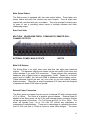
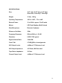
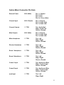
Solice Audio Mixer
Operation Manual
For mixers with pcb version 3.0
Copyright 2009
Professional Sound Corp
Table of Contents:
Introduction
4
Safety Warnings
4
Overview
4
Construction
5
INPUT SECTION:
Block Diagram
7
Input Panel View
8
Line / Microphone Input
9
Microphone Powering
9
Pre-Amplifiers
9
Gain Settings
9
High Pass Filters
10
Equalization
10
Limiters
10
Phase Reversal
10
Channel Assignment Switches
11
Channel Fader
12
Pre-Fade Listen Switch
12
Dedicated Line Outputs
12
Channel Ganging
13
Output Section panel View
14
2
Power Switch
14
Remote Roll
14
Reference Oscillator
15
Internal Slate Microphone
15
External Slate Microphone
16
Private Line
16
Comm System
16
Tape/Direct (Tape Returns)
17
M-S Stereo Decoding
17
Headphone Selections & Volume
17
Speaker Output
18
iPod Input
18
Peak Reading Meters
18
Main Output Faders
19
Rear Panel View
19
Main XLR Outputs
19
External Power Connection
19
Multi-Pin Connection
20
Specifications
21
Mixer Connector Pin Outs
22
RoHS
25
CE Mark
26
Warranty
27
3
Introduction
Thank you for purchasing the Professional Sound Corporation Solice Portable
Audio Mixer. The Solice Mixer is the result of our desire to provide you with a
comprehensive, yet simple to use portable mixer. This mixer has been designed
to handle multi-camera shots as well as multi-track recording. The Solice Mixer
provides extreme flexibility in signal routing, very high quality audio and field
friendly ergonomics in a compact, robust package. This new mixer design is the
result of several years work in developing our latest audio circuitry. Many of the
Solice’s design ideas came from you, our customers. We hope you will enjoy
using your Solice Audio Mixer for years to come.
Safety Warnings
The Solice Audio Mixer has been designed to be inherently safe to use. It
operates from low voltage DC only. The design complies with all current safety,
environmental and RF emission regulations. The safe use of this product is
determined primarily by the user. Please read and understand this entire user’s
manual before using your new Solice Mixer. Proper cabling is a must in, on and
around film and television production sets. Please always maintain proper and
safe headphone monitoring levels. If improperly used, this mixer can output
headphone levels that may result in permanent hearing loss. The owner and/or
user are to determine safe operating levels and maintain these levels at all times.
Professional Sound Corp, it’s owners, officers and employees accept no
responsibility for misuse of this mixer, whether intentional or not that may result
in personal injury and/or property damage. In addition, PSC reserves the right to
be held harmless for any liability caused by the use of this mixer with any other
equipment.
Overview
The Solice Portable Audio Mixer provides eight inputs each offering the following
comprehensive list of features:
•
•
•
•
•
•
•
•
•
•
•
Precision, Super Low Noise Pre-amplifier developed by PSC
Switchable Line or Microphone Input levels
Phase Reversal
Peak Detecting, Fast Acting Limiting
12T or 48PH Microphone Powering
Fully Variable Pre-Amp Gain
Fully Variable High Pass Filter
Pan Pot for Assignment to Outputs 1 & 2
Pre-Fade Listen
Both Pre-Fader and Post Fader Channel Meters
Pre-Fader or Post Fader Signals can be Individually Routed to any Output
Buss.
4
The Solice Mixer also provides a host of output capabilities:
•
•
•
•
•
•
•
•
•
•
•
8 main Balanced Outputs on Full Size XLR’s
Peak Reading, Sun Light Readable LED Meters
Slate Microphone
Reference Tone Oscillator
Tape Returns
Stereo, M-s Decoding and Mono headphone Selections
Separate Headphone Feeds For 2 Booms and 1 Director
Private Line Function
Duplex Boom Communication
Little Lite BNC Jack
Remote Roll Function
Construction
The Solice Mixer’s chassis forms a solid foundation for the mixer’s electronics.
The chassis is precision laser cut from sheet aircraft grade aluminum using a
state of the art laser made in Sweden. Laser cutting of the aluminum results in
less distortion of the panel than traditional hole punching. The resulting panel is
then formed using automated CNC controlled press brakes. The structural side
panels (located behind the billet aluminum sides) are then hand TIG welded on a
heavy, flat surface table. The final chassis is re-checked for straightness and
measured to insure all dimensions are within design specification.
The finished chassis is then Chem film plated so that it will resist corrosion and
offer years of trouble free service. The final step is the application of the epoxy
powder coat paint. This “powder” painting process uses an electrical charge to
attract the paint to the surface of the mixer. It provides superior adhesion and is
an environmentally friendly process as it does not release toxic solvents into the
air.
All silk-screen lettering on the Solice Mixer is applied to the back side of tough
Lexan tm overlays. Printing the lettering and graphics on the back side of a clear
overlay provides years of wear free use. Your fingers only rub against the sturdy
surface of the clear Lexan rather than wearing the lettering off as happens with
standard top surface silk-screening. After years of use, if your Lexan overlays
begin to get scratched or damaged, they can be replaced to re-new the
appearance of your Solice mixer.
The aluminum side panels are milled from solid billets using a Fadel CNC milling
center. After milling and de-burring, they are chem. Film plated for corrosion
resistance and then given a two-stage powder coat consisting of metallic silver
followed by a clear blue. Please note that if you ever remove these side panels,
5
you must use the same type and size screws when re-installing them. The use
of longer screws will interfere with the electronics within the mixer and cause
mixer damage.
The Solice mixer’s dust cover is formed from solid aluminum. It is easily
removed by simply pressing the two thumb buttons and sliding the cover towards
yourself.
6
Block Diagram
7
Input Channel Panel View
CHANNEL METERS, PRE-FADER and POST-FADER
PRE-AMPLIFIER GAIN CONTROL
HIGH PASS FILTER
HIGH FREQUENCY E.Q.
MID FREQUENCY ADJUST (PARAMETRIC)
MID FREQUENCY E.Q.
LOW FREQUENCY E.Q.
PAN POT,
CHANNEL LINE OUT LEVEL ADJUST
LINE/MIC INPUT SELECTION,
MICROPHONE POWER
LIMITER, AUDIO PHASE REVERSAL
MIX 1 & 2 (PAN POT) SELECT, LINE OUT SELECT
MIX BUSS 3 SELECT,
MIX BUSS 4 SELECT
MIX BUSS 5 SELECT,
MIX BUSS 6 SELECT
MIX BUSS 7 SELECT,
MIX BUSS 8 SELECT
PRE-FADE LISTEN SWITCH
8
Line or Microphone Input Levels
The Solice mixer has been designed and optimized to provide excellent preamplification of microphone level signals. In order to accept line level signals, an
input pad must be switched in. The Solice mixer contains switchable 40dB input
pads for this purpose. The switch is located on the front panel just below the Pan
pot. It is Labeled “L” for Line level signals and “M” for Microphone level signals.
Microphone Powering
The Solice Mixer is equipped to provide both 12T and 48PH microphone
powering to DIN standards. Each input channel has an individual power filter on
each of the 12T and 48PH power lines. This provides isolation between input
channels and helps keep the noise floor down when using powered
microphones. 12T microphone powering should only be used when powering
12T design microphones such as Sennheiser 416T.
48PH microphone
powering should only be used with 48PH microphones. When using dynamic
style microphones, the microphone powering should be switched off. You should
also turn off the microphone powering when using wireless receivers.
Pre-Amplifiers
The Pre-amplifiers used in the Solice Mixer were originally designed for our
Miranda Mixer. This design is the result of many engineering hours. This new
super low-noise design uses the latest in high performance semiconductors. The
semiconductors used in the pre-amplifier design offer impressive specifications
while consuming reasonable amounts of power. The fully variable gain structure
of the pre-amplifiers allows for gain changes on the fly. You no longer have to
worry about those coarse “stepped” gain changes found in other mixer designs.
The rotary gain control offers 55dB of adjustment range for extreme flexibility.
This allows the Solice mixer to work with low gain Dynamic microphones as well
as high gain condenser microphones.
Gain Setting
Because the Solice Mixer is equipped with both Pre-fader and Post-fader input
channel meters you can easily adjust both pre-amplifier gain and channel fader
settings quickly and easily. The Pre-fader meter can be used to properly set the
pre-amplifier gain. Simply adjust the gain setting until the meter occasional
“peaks” to the top “0” LED. Once set, you can mix without worry as you have
approximately 18dB of additional headroom in the pre-amplifier before clipping
occurs. The Post-fader meter can be used when routing post-fader audio to the
direct line output for multi-track recording. We believe that these two small
meters will be very helpful in your mixing endeavors.
9
High Pass Filters
Each input channel of the Solice mixer is equipped with a continuously variable
high pass filter. The filters are very useful for eliminating wind rumble and air
conditioning noise. These filters have a 12dB per octave slope and operate from
18Hz up to approximately 200Hz. When turned fully clockwise, the filter is set to
18Hz and your audio signal is flat. As you turn the knob counter clock-wise, the
filter’s -3dB cut off point is moved upward. When turned fully counter clock-wise,
the filter is set to its maximum setting and rolls off all signals below 200Hz. As a
general rule, you should only use as much low frequency roll off as needed to get
a good recording.
Equalization
The Solice mixer provides for 3-way equalization.
The High frequency
equalization is centered at approximately 8 KHz.
The Low frequency
equalization is centered at approximately 100Hz. The mid is variable from 1 KHz
to 3 KHz. Each of the EQ level controls offers approximately +/- 10dB of
adjustment.
Limiters
Each input channel of the Solice mixer is equipped with a precision limiter.
These limiters are switchable on or off via a front panel mounted switch. It is
highly recommended that the input limiters be used at all times. They will save
you from input channel overload and clipping. When turned “On” and when
supplied with audio that is at and beyond the preset activation level, the limiters
begin limiting and the top “0” led of the Pre-fader channel meter will glow RED.
This LED is a two color LED and will also show Green if the audio level is at “0”
dB or above. Thus it is normal to have both segments of the LED lit at once.
This Red and Green lighted at the same time will show up as an Orange color.
This is a perfectly normal condition. The limiters are internally adjustable for both
activation level and for limiting ratio. The limiters are factory set to activate at
+2dB on the Pre-fader channel meter and they limit at a ratio starting at
approximately 2.7 to 1 up to a ratio of approximately 50 to 1. These ratios were
chosen based on years of customer feedback. Please note that the limiters
must be adjusted only by qualified technician who has access to precision test
equipment.
Do not try to adjust these limiters yourself. Calibrating eight
separate limiters without the proper electronic test equipment will lead to poor
results.
Phase Reversal
Each input channel of the Solice Mixer is equipped with an audio phase inversion
switch. These switches are used when recording with multiple microphones of
different makes and models. Sometime you may encounter a microphone with
10
audio that is out of phase with the other microphones. When this happens, there
exists the possibility that the two microphones will cancel out each others signals
when in close proximity to each other. This is simple to correct by reversing the
phase of the offending microphone.
These Phase reversing switches are
labeled as “180” on the panel of the mixer. “180” refers to the audio signal being
180 degrees out of phase.
Channel Assignment Switches:
The Solice mixer brings channel assignment (signal routing) to a new level.
Each input channel of the Solice mixer offers many channel assignment
possibilities. Having a full understanding of these routing possibilities will
allow you to meet the needs of virtually all your mixing requirements and
those of your director and producers too! Basically, all eight of the audio
assignment switches have three functions. Just remember these three
functions:
Left = Pre-Fader Audio
Center = Off
Right = Post-Fader Audio
The Various Assignments Include:
Direct Line Output:
Each input channel on the Solice mixer is equipped with a dedicated direct line
output. This output can be used to feed multi-track recorders when recording
separate tracks for each actor. The direct line output is located on the rear of
the mixer just above each input XLR connector. These line outputs offer a
balanced audio signal on a standard ¼ TRS connector. Tip is audio High, Ring
is audio Low and the Sleeve is ground. These outputs use the same high quality
electronics as do the main XLR outputs. Because of this, they offer the same low
noise, high headroom characteristics as the main outputs. There are several
controls and options when using these outputs. There is a 3 way toggle switch
that is labeled “LINE OUT” This switch selects between Pre-Fader audio when
switched to the left, No Audio when switched to the center position and PostFader audio when it is switched to the right. Having these three choices for each
of the channel outputs offers you, the mixer a great deal of flexibility. In addition,
there is a rotary level control that is also labeled “LINE OUT”. This control
allows the user to set the line output level anywhere from full output (fully clockwise rotation) to no output (fully counter clock-wise rotation) or anywhere in
between for added flexibility.
Channel 1&2:
Signals routed to main outputs 1 and 2 are handled somewhat differently than
those routed to the remaining main outputs 3 through 8. Signals routed to
channel 1 and 2 are also selected as Pre-Fader, Off or Post-Fader just like the
11
dedicated line output. However, once you have selected Pre-Fader or PostFader, the signal you selected is then routed through the Pan Pot so you as the
operator can pan it hard Left (Channel 1 output), hard Right (Channel 2 output)
or anywhere in between. This is useful for music recordings and also for stereo
mixdowns for dailies. Normally, you would use main outputs 1 and 2 as a stereo
pair for dailies.
Channels 3 to 8:
Channels 3 through 8 are handled in a similar way. They also incorporate the 3way toggle switch allowing your choice of Pre-Fader, Off or Post-Fader audio
feeds. They are somewhat simplified in that they do not have any panning
function built into them. Main outputs 3 through 8 can be used for 3 stereo pairs
to feed 3 cameras, or for multi-track recording or for combinations of these two.
Channel Fader
The Solice mixer is equipped with Penny and Giles conductive plastic faders.
These faders have proven themselves over the years as the best possible fader
for professional portable mixer use. These faders offer silky smooth operation
and are generally noise free.
The channel faders offer more than 70dB of
control range at your finger tips. The mixer overlays are labeled with coarse
lines every 10dB under the fader knobs for operator convenience.
Recommended normal operating range is at the “0” line. This will leave you with
an additional 10dB of signal range if needed for those hard to mic actors.
Pre-Fade Listen Switch
Each input channel of the Solice mixer is equipped with a Pre-Fader Listen
switch. These momentary contact, red pushbutton switches are located at the
bottom of each input channel. When pressed, pre-fader audio from that
individual input channel is routed directly to the Mixer’s headphones. Thus the
mixer can quickly and easily monitor individual microphones (or wireless) without
having to open the channel fader (pot up that channel) This allows the mixer to
check on the audio quality and level of any individual microphone even while
recording using other inputs.
Dedicated Line Outputs
Each of the eight input channels is equipped with a dedicated, balanced line
output on a ¼” stereo connector. This balanced output is very high quality; in
fact, it uses the same circuitry as the main XLR balanced outputs.
These
dedicated line outputs can drive up to a +20dBm signal for maximum headroom.
Input channel signals are routed to the dedicated line output via the “Line Out”
toggle switch and line out rotary level pot. The toggle switch has three positions.
Switched to the Left, it feeds the dedicated line output with Pre-fader audio.
12
Switched to the Center position, it switches off the audio to the dedicated line
output. Switched to the Right, the dedicated line output is fed Post-fader audio.
The Line output level pot controls the level of the dedicated line output. It allows
full control of the audio level from full off (counter clock-wise) to fully on (fully
clock-wise) or anywhere in between.
Channel Ganging
Input channels 1 and 2 and also input channels 3 and 4 can be ganged together
into stereo pairs for ease of use in making stereo recordings. This is useful
when working in both XY and MS configurations. There is a simple ganging
switch located between each of these channels. It is labeled “GANG” and “SEP”.
In the Separate position, the input channels operate as standard mono inputs
and they have no effect on each other. When set to the Ganged position, the
first channel fader of the stereo pair will control the level of the entire stereo pair.
Thus, when inputs 1 and 2 are ganged together, fader 1 will have control over
both inputs 1 and 2. The same is true when inputs 3 and 4 are ganged together.
Fader #3 will have control over inputs 3 and 4. For those times when you are
using a stereo microphone or a stereo pair of mono microphones, this ganged
input fader will allow you to make level adjustments while recording without
affecting the stereo image.
13
Output Section Panel View
BNC FOR “LED” LITTLE LITE
MAIN OUTPUT METERS 1- 8
MAIN POWER SWITCH
REMOTE ROLL SWITCH
SLATE MIC, SPKR VOLUME
REFERENCE OSC SWITCH
HEADPHONE VOLUMES
SLATE MICROPHONE SWITCH
HEADPHONE FEED SELECTS
PRIVATE LINE SWITCH
MIXER HEADPHONE MODE
TAPE / DIRECT SWITCH
BOOM COMMUNICATION
Power Switch
The main power switch for the Solice mixer isolated along the right hand edge of
the mixer. It is the top most large, square push button switches. This switch is a
latching type. Press it once to turn on the mixer and press it again to turn off the
mixer. When the mixer is powered on, this switch will be lit blue.
14
Remote Roll
The Solice mixer is equipped with a basic remote roll function. This remote roll
switch can be used to remotely control some recorders as well as red light
systems, etc. On the rear panel of the mixer is a ¼ jack labeled “Remote Roll”.
This jack has the TIP and RING connections switched via a small relay built into
the mixer. These contacts are factory set to close (make contact) when the roll
switch is pressed and latched in the down position.
In addition, the switch is
equipped with two color back lighting for ease of use on dark sound stages.
When in the Stop position (up) the switch is lit RED. When Roll position
(depressed) it is lit GREEN.
Reference Oscillator
The Solice mixer is equipped with a Reference Tone Oscillator. This oscillator is
used for setting reference levels at the beginning of all recordings. These levels
are used later in editing to match all scene levels so that your finished audio is
consistent and high quality. When the Reference Oscillator button is pressed, a
1 kHz oscillator is activated and routed to all eight main outputs as well as the
eight individual dedicated channel outputs. These dedicated channel outputs
are typically used for multi-track recording. Whenever the reference oscillator is
activated, all eight of the input channels are automatically muted. This allows
only a pure reference tone to be recorded for easier editing later.
Internal Slate Microphone
The Solice mixer is equipped with a built in Slate Microphone used for voice
slating of takes, mixer voice notes, etc. This same built in microphone is used
for the Private Line function that allows the mixer operator to talk to the boom
operators. This microphone is also used for full duplex “Boom Communication”
in which the operator of the mixer can talk to the boom operators and they in turn
can talk back to the mixer operator and each other. When the slate microphone
is activated, all eight input channels are momentarily muted for better slating
clarity.
15
External Slate Microphone
If you prefer to use an external slate microphone rather that the internal slate
microphone, you must simply plug an appropriate microphone into the external
slate microphone ¼” connector located on the right, front edge of the mixer near
the mixer’s headphone jack. These two jacks were purposely placed next to
each other to allow the use of headsets with built in microphone booms. The
external slate microphone input jack contains switch contacts that automatically
switch over from internal slate microphone to external as soon as you plug in the
external microphone.
Private Line
The Solice mixer is equipped with a private line function which allows the mixer
operator to speak to the two boom operators at will. When this momentary
switch is pressed, the slate microphone is routed to the two boom operator’s
headphones. Thus the mixer can talk to the two boom operators.
Comm System
In addition to the Private Line function, the Solice mixer is equipped with a full
duplex communication system. This system allows the mixer to talk to the two
boom operators and it also allows the two boom operators to talk back to the
mixer’s operator as well as each other. This momentary switch will activate the
system for as long as it is pressed. In addition, the rear panel of the Solice mixer
has two ¼ jacks labeled “ COMM 1” and “COMM 2”. These two jacks provide
audio inputs to the mixer form the two boom operators allowing them to speak.
The jacks are wired as follows” TIP is Audio and it includes a 5V bias for
operating electret microphones.
RING is a logic control line, and SLEVE is
Ground. When the RING terminal is grounded, the Comm System is activated.
Thus it is possible for either boom operator to activate the system at will. All that
is required is a special boom operator cable that has a talk back line included.
These can be purchased through any PSC dealer.
16
Tape / Direct (Tape Returns)
The Mixer’s headphone monitoring section allows for the use of tape returns.
These “Tape Return Audio Inputs” are contained on the DB-37 Multi-pin
connector on the rear panel of the Solice Mixer. There are eight tape returns to
go along with the eight main outputs. These tape returns allow the operator to
monitor “Tape” confidence (old term for recording verification) to insure that audio
is actually being recorded. Some recorders offer this recording confidence as an
output which can be connected to the Solice Mixer’s tape inputs. When the
operator desires to check the tape inputs, he or she simply presses the
Tape/Direct push button switch and his or her headphones are automatically
switched to monitor the tape return inputs. The headphone selection switch is
still active and thus if you were monitoring the mixers outputs 1 and 2, when you
switch to “tape” you will be monitoring the tape returns 1 and 2. The same holds
true for all of the other headphone selections except for “iPod” and inputs
“Channel 1”. These two setting do not offer any tape return function, so if you
switch to tape, these settings will not change.
M-S Stereo Decoding
The Solice mixer will allow decoding of MS stereo signals sent to the mixer’s
headphones. There is a 3-way toggle switch located on the main mixer panel
that is labeled “M-S”, “STEREO”, and “MONO” This 3-way switch controls the
audio signal going to the mixers headphone feed. It does not control the feeds
going to the Director or two Boom Operators headphone feeds. When switched
to M-S, MS stereo signals are decoded into standard XY stereo signals for the
operator of the mixer to listen to. This setting is only used when making MS
stereo recordings. The “STEREO” setting is used for most applications. When
set to this position, the mixer’s headphones will receive standard stereo signals.
When set to “MONO” the mixer’s headphone signals are mono’d together. This
is useful for checking phasing problems between various microphones and
wireless.
Headphone Selection
Each of the four headphone feeds has a rotary selection switch that has six
positions. Each of these positions selects a specific audio source to feed to that
particular operator’s headphones. This is convenient for allowing the users to
pick their own individual audio source.
The Solice mixer is equipped with four independent stereo headphone feeds.
These are labeled on the mixer as “Mixer”, “Director”, “Boom 1” and “Boom 2”.
17
Each of these four feeds is equipped with it’s own audio source selection switch
and it’s own volume control. The “Mixers” feed is routed to a ¼” jack located on
the right side front edge of the Solice mixer. The remaining outs for the Director
and two boom operators are located on the rear panel of the mixer. The two
Boom operator feeds and the Director feed have an input source selection
labeled as “X”. When switched to this position, they are fed the same audio as is
monitored by the Mixer headphone feed. That is to say, they are fed a copy of
whatever the mixer selection switch is set to. Thus everyone can easily and
quickly monitor the same thing. The headphone outputs are rated to operate into
headphones with impedances from 20 to 600 ohms. As with all headphone use,
please monitor your headphone volume carefully and always use the lowest
practical volume setting. Excessive sound pressure levels will cause permanent
hearing loss. Your ears are your livelihood. “Turn it Down”
Headphone Volume
Headphone volume is adjusted by using the four headphone volume pots located
just above the four headphone audio selection switches. These headphone
volume controls allow a full range of adjustment from fully off (counter clock-wise)
to full on (clock-wise). Please be careful when setting headphone volume levels
as excessive headphone levels can cause permanent hearing damage. User
determines proper and safe operating levels.
Speaker Output
The Solice Mixer is equipped with a “Speaker” output that is used to feed PA
systems for playback work, on set audio monitoring and other uses. This feed
provides the same audio as selected by the Mixer’s headphone selection switch.
It is basically a copy of the headphone output, but with it’s own level control.
iPOD Input
The Ipod input provides another source of audio that can be feed to the
headphone amplifiers and also the Speaker outputs. This input is typically used
for supplying music to the set during down time. It can also be used for an audio
input form Video Village for playback of audio through the Solice mixer.
Peak Reading Meters
The Solice mixer is equipped with eight output meters. Each of these meters is
LED based and read from -36dB to +12dB. They are color coded for ease of
use. All LED’s representing audio levels form -36dB up to -3dB are Green in
color. The LED’s that represents a “0” level are Yellow in color and all LED’s
from +3dB up to +12dB are Red in color. These meters are peak reading and
have ballistics that are conducive to quality field recordings.
18
Main Output Faders
The Solice mixer is equipped with four main output faders. These faders are
stereo faders and each one controls two main outputs. Thus all eight main
outputs are controlled with only four faders. They are arranged in stereo pairs
for ease of use in providing stereo sends to multiple cameras and other
challenging setups.
Rear Panel View
MULTI-PIN, HEADPHONE FEEDS, COMM INPUTS, REMOTE ROLL,
CHANNEL OUTPUTS
EXTERNAL POWER, MAIN OUTPUTS,
INPUTS
Main XLR Outputs
The Solice Mixer is an eight buss mixer and thus has eight main balanced
outputs. The balanced outputs are located on the rear panel of the mixer and
utilize standard 3 pin male XLR connectors. These outputs offer exceptional
headroom with a clipping level of approximately +24dB. Based on a nominal
output level of +4dBm, you still have 20dB of headroom before clipping occurs.
These balanced outputs are also very low noise for use with today’s modern
digital recorders. They offer an output impedance of 50 ohms and are designed
to operate into loads of 600 ohms or greater.
External Power Connection
The Solice mixer is powered from any source of external DC with a voltage range
of 10 to 18Vdc. The Solice is a negative ground chassis. External power is
applied to the Solice mixer via the 4 pin male external power connector located
on the rear panel of the mixer. Pin 1 is Ground and Pin 4 is 10 to 18Vdc. The
mixer will operate from +10 to +18 volts DC without any adjustment or
compromise in specifications. There are no advantages to operating the mixer
from 18 Vdc over that of 12Vdc as found on some other designs. The mixer
19
typically consumes approximately 13.8 watts (1 amp @ 13.8Vdc). The mixer will
consume up to a worst case of about 19 watts when all LED’s are lit. This is
unlikely in normal use.
DO NOT SUPPLY THE SOLICE MIXER WITH DC VOLTAGES THAT ARE IN
EXCESS OF 18VOLTS DC! DAMAGE TO THE MIXER WILL RESULT AND
THIS DAMAGE WILL NOT BE REPAIRED UNDER WARRANTY.
Multi-Pin Connector
The rear panel of the Solice Mixer is equipped with a DB-37 Female connector.
This connector provides a parallel set of the eight main balanced outputs, eight
tape returns, and various DC voltages for powering auxiliary equipment. For
those users who will be sending the 8 main outputs to an eight track recorder,
you can use the DD-37 pin connector rather than eight individual XLR cables.
This connector is also used for tape return functions. We included DC power on
this connector for possible future product expansion modules made by PSC.
20
SPECIFICATIONS:
Size:
16.5” wide, 16.00” deep, 3.00” high
42cm wide, 41cm deep, 7.6cm high
Weight:
15 Lbs, 6.8 Kg
Operating Temperature:
-20F to +120F, -7C to +49C
External Power:
10 to 18Vdc, approx 13 to 20 watts
Meters:
LED, Peak Reading, Multi-Colored
Slate Microphone:
Electrete Condenser
Reference Oscillator:
1KHz
Frequency Response:
20Hz to 20Khz +/- 0.5 dB
Distortion:
0.025% THD, typical
Signal to Noise Ratio:
130db EIN
Cross Talk:
>75dB @1Khz, via assignments
XLR Output Levels:
+4dBm at “0” Reference Level.
XLR Output Impedance:
<25 Ohms, 600 Ohm rated
Tape Return Impedance:
1K Ohm
Channel Output Level:
+4dBm at “0” Reference Level
21
Solice Mixer Connector Pin Outs
External Power
XLR-4-Male
Pin 1 = Ground
Pin 2 = N.C.
Pin 3 = N.C.
Pin 4 = +10 to +18Vdc
Channel Input
XLR-3-Female
Pin 1 = Ground
Pin 2 = Audio High
Pin 3 = Audio Low
Channel Outputs
¼” TRS
Tip = Audio High
Ring = Audio Low
Sleeve = Ground
Main Outputs
XLR-3-Male
Pin 1 = Ground
Pin 2 = Audio High
Pin 3 = Audio Low
Mixer Headphone
¼” TRS
Tip = Left
Ring = Right
Sleeve = Ground
Director Headphone
¼” TRS
Tip = Left
Ring = Right
Sleeve = Ground
Boom 1 Headphone
¼” TRS
Tip = Left
Ring = Right
Sleeve = Ground
Boom 2 Headphone
¼” TRS
Tip = Left
Ring = Right
Sleeve = Ground
Comm 1 Input
¼” TRS
Tip = Audio and +Bias
Ring = Control Logic
Sleeve = Ground
Comm 2 Input
¼” TRS
Tip = Audio and +Bias
Ring = Control Logic
Sleeve = Ground
Ipod Input
¼” TRS
Tip = Left
Ring = Right
22
Sleeve = Ground
Ext Slate Mic Input
¼” TRS
Tip = Audio and +Bias
Ring = N.C.
Sleeve = Ground
Remote Roll
¼” TRS
Tip = Switched Contact
Ring = Switched Contact
Sleeve = N.C.
Multi-Pin
DB-37 Female
Balanced Outputs:
Pin 1 = Main Out 1 High
Pin 20 = Main Out 1 Low
Pin 2 = Main Out 2 High
Pin 21 = Main Out 2 Low
Pin 3 = Main Out 3 High
Pin 22 = Main Out 3 Low
Pin 4 = Main Out 4 High
Pin 23 = Main Out 4 Low
Pin 5 = Main Out 5 High
Pin 24 = Main Out 5 Low
Pin 6 = Main Out 6 High
Pin 25 = Main Out 6 Low
Pin 7 = Main Out 7 High
Pin 26 = Main Out 7 Low
Pin 8 = Main Out 8 High
Pin 27 = Main Out 8 Low
Grounds:
Pins 9, 10, 28, 29 All Ground
Tape Returns:
Pin 11 = Tape Input 1
Pin 30 = Tape Input 2
Pin 12 = Tape Input 3
Pin 31 = Tape Input 4
Pin 13 = Tape Input 5
Pin 32 = Tape Input 6
Pin 14 = Tape Input 7
23
Pin 33 = Tape Input 8
Power Outputs:
Pin 15, 16, 34, 35 Unreg V+ 500mA
Pin 18, 38, +12Vdc, 50mA
Pin 19, 37, -12Vdc, 50mA
24
RoHS Certificate of Compliance
Professional Sound Corporation certifies that all products designated by
Professional Sound Corporation as “PB-Free”, “RoHS Compliant” or “Green” are
compliant with the requirements of the European Union’s Restriction on Use of
Hazardous Substances (“RoHS”) Directive, 2002/95/EC.
Professional Sound Corporation bases its material content knowledge on
information provided by third parties, including parts manufacturers, distributors
and vendors. Only RoHS certified parts and sub-assemblies are used in the
assembly of Professional Sound Corporation products. Additionally Professional
Sound Corporation has taken and continues to take commercially reasonable
steps to insure that its parts suppliers, subcontractors and assembly houses are
RoHS compliant.
Level A Banned Substances
Asbestos
Azo colorants
Cadmium
Hexavalent Chromium
Lead
Polybrominated Biphenyls (PBB’s)
Polybrominated
Diphenyl
Ethers
(PBDE’s)
Polychlorinated Biphenys (PCB’s)
Threshold, Homogeneous Level
Not intentionally added
Not intentionally added
100 ppm, Not intentionally added
1000 ppm, Not intentionally added
1000 ppm, Not intentionally added
1000 ppm, Not intentionally added
1000 ppm, Not intentionally added
Not intentionally added
Professional Sound Corporation certifies that all products made on or after June
30th, 2006 to be RoHS Compliant. All such products will be clearly marked with
Professional Sound Corporation “compliant” label. This label assures the reseller
end user that the product is RoHS Compliant. An example of this label is shown
below:
RoHS
Compliant
Ronald Meyer
President
Date: July 1st, 2006
25
CE
DECLARATION OF CONFORMITY
EMC:
This product is in compliance with the
Electromagnetic
Compatibility
Directive,
89/336/EEC as defined in EN 50081-1, EN55022
and EN 50082-1. IEC801-2, IEC801-3 and IEC801-4.
LVD:
This product is in compliance with the
requirements of the Low Voltage Directive,
73/23/EEC. 93/68/EEC as defined in EN60065, 1993
and/or EN60950/A1/A2/A3: 1995
TRADE NAME:
PSC
MODEL:
Solice Audio Mixer
RESPONSIBLE PARTY: Professional Sound Corp.
CONTACT PERSON:
TYPE OF PRODUCT:
MANUFACTURER:
28085 Smyth Drive
Valencia, CA 91355 USA
Ronald Meyer
(661) 295-9395
Analog Audio Mixer
Professional Sound Corp.
28083 Smyth drive
Valencia, CA 91355 USA
We hereby declare that the equipment bearing the trade name and model number
listed above has been tested in accordance with the requirements contained in the
above listed directives. All necessary steps have been taken and are in force to
assure that production units manufactured will conform to Directive guidelines.
December 2008
Professional Sound Corporation.
26
PSC Solice Mixer Limited Warranty
Professional Sound Corporation warrants the Solice Audio Mixer to be free of
defective material and workmanship for a period of one year from the original date
of purchase and agrees to repair or replace such defective parts or the whole
product at it’s option, provided that the equipment is returned to Professional
Sound Corporation. Shipping and insurance costs to and from Professional
Sound Corporation must be prepaid by the owner. This warranty does not cover
damage due to accident, careless handling, abuse or misuse, improper
connection and/or installation, improper electrical contact or grounding. This
warranty will be null and void in the event of removal, alteration or tampering with
the serial number, or by breakage of the product case seal, or by service or repair
work not performed by Professional Sound Corporation. Proof of purchase date
(copy of invoice or Warranty Certificate) must be furnished before warranty
service will be performed. This warranty is in lieu of any other warranty,
expressed or implied, including warranties without limitation, products being
merchantable at the time of purchase or suitable for a particular purpose. This
warranty does not extend to, or include consequential damage.
Copyright 2009 PSC
All technologies employed in the design and manufacturing of the Solice
Mixer remain the proprietary property of Professional Sound Corp. All
Rights Reserved
Professional Sound Corporation
28085 Smyth Drive
Valencia, CA 91355
PH 661-295-9395 FAX 661-295-8398
[email protected] www.professionalsound.com
27