1
MILLI'Q
A10
Academic "Gradient ;y
Biocel '
Synthesis /
MILLIPORE
Milli-Q - User Manual
Page 1 of 34
Operating and
Maintenance manual
MILLI-Q
A10
Academic,-Gradient,/-' /
Biocel''
/
Synthesis /
MILUPORE
Milli-Q - User
L
NOTICE
Information in this document is subject to change without notice and should not be
construed as a commitment by Millipore Corporation. Millipore Corporation assumes no
responsibility for any errors that may appear in this document. This manual is believed to
be complete and accurate at the time of publication. In no event shall Millipore
Corporation be liable for incidental or consequential damages in connection with or arising
from the use of this manual.
Copyright © 1997, all rights reserved, Millipore Corporation.
Folder:
PF 0
Documentation: PF 05112
Trademarks
Millipore is a registered trademark of Millipore Corporation or an affiliated company.
RiOs, Elix, Milli-Q, Q-Gard and Quantum are trademarks of Millipore Corporation.
Teflon is a trademark of E.I. duPont de Nemours & Co.
Slo-Blo is a trademark of Little Fuse Company
All other trademarks are trademarks of their respective manufacturer.
Milli-Q - User Manual
Page 3 of 34
TABLE OF CONTENT
w
U
NOTICE
3
TABLE OF CONTENT
4
USING OF THE MANUAL
5
DISTINGUISHING BETWEEN TEXT SPECIFIC TO ONE OR MORE MlLLI-Q SYSTEMS
5
WARNINGS
5
INTRODUCTION
6
GENERAL INFORMATION
6
HOWTHE SYSTEM WORKS
SYSTEM SCHEMATIC
SPECIFICATIONS
6
7
8
INSTALLATION
w
/
1
*""
u
10
UNPACKING
INSTALLATION OF THE SYSTEM
INSTALLATION
10
10
11
OPERATING THE MILLI-Q SYSTEM
14
MODES OF OPERATION
STANDARD DISPLAYS
ADDITIONAL DISPLAYS
USE OF THE KEYPAD
STARTUP OF THE MILLI-Q
14
14
15
17
21
MAINTENANCE
22
TIMETABLE FOR ROUTINE MAINTENANCE
,,..,
22
I
ROUTINE MAINTENANCE
..',.
.;,..
22
^
TROUBLESHOOTING
...
;;,,.
26
XOUBLESHOOTING MESSAGES
26
"""LIST OF ALARM CODES
28
APPENDIX 1
30
INTERRUPTING THE SANITISATION CYCLE OF A UF CARTRIDGE...............,,....
30
w
PURGING TRAPPED AIR FROM THE UF CARTRIDGE.:
INTERRUPTING THE A - 1 0 CLEANING CYCLE
REPLACING THE MAIN ELECTRICAL POWER FUSE
REGULATING THE MOBILITY OF THE POINT OF USE ARM
RECYCLING THE REJECT WATER FROM THE A - 1 0 T O C
SYSTEM IS NOT OPERATED FOR A LONG TIME
TECHNICAL INFORMATION
30
30
31
31
31
31
33
I
TECHNICAL ASSISTANCE
WARRANTY
;
:
At the end of the document
FIGURES
<
'—
L
Milli-Q - User Manual
...1...
...•
33
34
Page 4 of 34
USING OF THE MANUAL
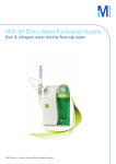
This manual describes how to install, use and maintain your Milli-Q water purification system. The use of this
equipment is very simple; however, it is strongly recommended that this manual be read before connecting the
system to a source of water or to electrical power. A thorough knowledge of your water system not only helps to
prevent damage to the system or personal injury, but it also helps you to become familiar with all its functions.
Distinguishing between text specific to one or more Milli-O systems
The information presented in this manual uses the following notation:
"'
The four types of Milli-Q systems and the A-10 TOC option are described in this manual.
The guide shown on the edge of each page permits you to distinguish between information relevant to all
models or to information relevant to a specific model of water system.
It is important to verify that the column on the edge of the page corresponding to your model is full before
proceeding to study information pertaining to system characteristics, operations,...
Example:
FOR COMMON TEXT
FOR TEXT SPECIFIC TO A SPECIFIC MODEL: Gradient
: all the columns are full.
column 2 is full
All reference figures are located at the back of this manual, in A3 foldout sheets.
Dotted portions of drawings represent components or items not delivered with the system.
Elements shown in light grey represent keypad buttons which are not being referred to in that section of text,
or not referred to in examples of screen displays.
Warnings
Caution signs are shown throughout this manual to bring items to your attention which present risk or which
require delicate manipulations.
: Caution.
: Danger.
Milli-Q - User Manual
Page 5 of 34
MUl-Q
Ac. Gf.Bio.Syn.Al
Mtll-Q
fe Q. Bco.SynAl
INTRODUCTION
General Information
The Milli-Q system is used as a final water purification stage. The feedwater to a Milli-Q can be produced by
electrodeionisation (ELIX), Reverse Osmosis (RO), distillation or deionisation.
The Milli-Q system produces water of Type 1 quality. This is equal to or better than ASTM, CAP and NCCLS
type 1 water quality standards.
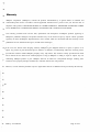
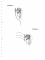
The principal components of the Milli-Q system, Figure 1, are:
(A)
? o n t F°! P? n e l
(B)
Q-Gard pack adapter
c
'.
(D)
(E)
(F)
(G)
Door for locking QUANTUM purification cartridge
Liquid-Crystal Display (LCD)"
LED Indicator'
Keypad
(H)
9 ^ 9 1 ? Power Switch"
( ) I.IILZI..II1IZZZ1ZZZZZZ Z'"1
s
(I)
(J)
(K)
(L)
(M)
(N)
(O)
(P)
Q'^fi^jf
Power cord socket
Fuse'Holder
_
Fittings / inserts for water connection
Sanitisation port plug for cleaning the UF moduie
Point of Use Gun with support arm
Sticker with serial number, iot number and system type
Locking clip screws
Locking clips
"77"
How the system works
Pre-treated water (from EDI, Reverse Osmosis, distillation or deionisation) enters the system and is pumped through
^he Q-Gard pack for an initial purification step.
The water is then exposed to UV light at both 185 and 254 pm wavelengths which oxidises organic compounds and
kills bacteria.
The function of the QUANTUM cartridge is to remove trace ions and oxidation by products produced by the action
oftheUV light.
Purified water then passes through an Ultrafiltration (UF) module. The UF module acts as a barrier to colloids,
particles and organic molecules with a molecular weight greater than 5000 Daltons. The contaminants retained by the
UF are periodically flushed out of the system via tubing to a drain.
A manual 3 way valve allows you to direct ultrapure water through a final filter made up of a 0.22 um membrane
(MilliPak-40). The final filter removes particles and bacteria greater than 0.22 um in size and prevents
recontamination of the system from the point of use.
The A-10 TOC monitor takes samples of ultrapure water to determine trace organic levels. Samples are taken
periodically in PRODUCT mode.
Milli-Q - User Manual
Page 6 of 34
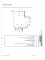
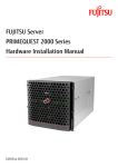
System Schematic
The water flow schematic of a Milli-Q system is shown below. Only the main components are shown.
MIUJ-Q
Ac. Gc. BiaSynAlO
Inlet solenoid valve
Pump
Q-Gard Pack (selected based upon the type of feedwater)
QUANTUM ultrapure cartridge
Resistivity cell
Point of use with dispensing valve
MILLIPAK 40 final filter
Check valve
;
UVlamp
Sanitisation port used to introduce chemical sanitants to UF module
Ultrafiltration cartridge
UF cartridge reject solenoid valve
A-10TOC monitor
Milli-Q - User Manual
Page 7 of 34
1
2
3
4
5
6
7
8
9
10
11
12
13
Specifications
MLU-Q
Ac. Q.
Composition of materials in contact with water
Pieces
Pack Adapter :
Q-Gard Pack
Inlet solenoid valve :
QUANTUM cartridge
Pump head:
Material
ABS
PP, PE
Stainless steel
Ultra-High density
polyethylene
NSF* listed and FDA*
approved materials
Pieces
ivi"iLLIPAK40"
Fittings :
Resistivity cell :
Manifold:
Tubing:
Three way valve :
O-rings :
UV lamp and housing:
UF housing :
UF sanitisation port :
Reject solenoid valve :
Material
Polycarbonate, PVDF
PE, PA, PVDF
Stainless steel 316 L
PPO
PE
Copolymer of butadiene
and styrene, Viton, PTFE
EPDM
Quartz, Stainless steel
ABS
ABS
Stainless steel
*NSF = National Sanitation Foundation * FDA = Food and Drug Administration
Electrical specifications
Frequency
Main power fuse
230 Volts
120 Volts
Electrical
consumption
60 VA
60 VA
50 Hz
60 Hz
1.0ASlo-Blo'M
2.0 A Slo-Blo
230 Volts
120 Volts
100 VA
100 VA
50 Hz
60 Hz
1.0 A Slo-Blo.
2.0 A Slo-Blo.
Voltage
RS 232 Output
RS232
type RJ 11
connector
Dimensions and operating weight (with Q-Gard and Quantum)
Height
Length
Depth
Weight(s)
455 mm
255 mm
355 mm (includes the wall
mounting points on rear)
,
... 16.0 Kg
16.8 Kg
16.3 Kg
17.1 Kg
+ 0.6 Kg with A-10 TOC module
Environmental Conditions
Ambient storage and operating temperature
5°C<T<40°C
Humidity
2 0 % - 80% without
condensation
Milli-Q - User Manual
Page 8 of 34
MUI-Q
M. Q.
Hydraulic specifications
Feedwater tubing
Reject tubing
Inlet feedwater pressure
8 mm outer diameter (OD)
length : 3 meters maximum
8 mm and 6 mm OD
length : 2.5 meters maximum
Minimum: 0.1 bar (1.5 psi)
Maximum: 0.3 bar (4.5 psi)
Feedwater flowrate
> 1.5 litre/minute (LPM)
Feedwater temperature
5 °C to 37 °C
^^^eedwater quality
Millipore recommends using water treated by ELIX (Electrodeionisation, EDI) or Reverse Osmosis (RiOs).
System performance
Purified water quality
Resistivity
18.2MQ-cmat25°C
Pyrogens
< 0.02 EU/ml
TOC*
5-10 ppb
1 - 5. ' ppb
2-5
ppi)
Silicates
Heavy metals
Micro-organisms
Particles (0.22 urn)
<0,l ppb
£0,1 ppb
< 1 cfu/ml
<l/mlV
Flowrates
Product water flowrate
Uptol.5 litre/minute
Up to 1.0 litre/minute
Noise level in dB A at 1 metre
* Test conditions: Milli-Q system was equipped with a Q-Gard purification pack and a QUANTUM EX ultrapure
cartridge. The feedwater to the Milli-Q came from a RiOs Reverse Osmosis system. TOC levels in the feedwater
were < 50 ppb. The quality of the Milli-Q product water can vary as a function of the quality of the feedwater.
Milli-Q - User Manual
Page 9 of 34
MU1Q
A:. O.BiaSynAlO
INSTALLATION
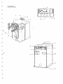
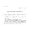
Unpacking
The different components supplied with the system are shown in figure 2 and are listed below.
Present ?
I yes I no
(A)
(B)
(C)
(D)
Milli-Q water purification system
Electrical power cord
Folder with documents to insert
Tubing 8 mm OD, 5 meters length for :
- inlet water connection
- reject stream for ultrafiltration module
Tubing (6 mm OD), 2.5 meters length for A-10 waste stream
Tubing used when UF module is sanitised
Fitting 1/4" MNPT - hose barb (MNPT = male national pipe thread)
Fitting 1/2" FNPT - 8 mm OD tubing with screen filter inside
Teflon™ tape
Plastic bag containing elbow fittings
Six sided key used to loosen / tighten point of use arm
"'
(E)
(F)
(G)
(H)
(I)
(J)
(K)
i
_
Items ordered separately
(L)
Q-Gard purification pack
(M)
QUANTUM ultrapure cartridge
(N)
MILLIPAK 40 final filter (0.22 urn) for point of use gun
Checked by
Name
Signature
Date
Name
Signature
Date
Verified by
Installation of the system
The system can either be placed on a bench or wall mounted. If the system is to be wall mounted,
then it is necessary to first verify that the wall can support the weight of the system. Contact
Millipore Technical Service for further instructions on wall mounting the system.
Some versions of the Milli-Q systems require a drain nearby. When a reservoir is used as a
feedwater supply, locate the system and reservoir close together whenever possible.
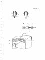
Figure 5 shows the different connections to be made to the system.
Note: The inlet valve, pressure regulator and pressure gauge are not supplied with the Milli-Q and must be
ordered separately. Contact Millipore Technical Service for more information.
Milli-Q - User Manual
Page 10 of 34
MU1-Q
Ac. Q. Bio.Syn.Al
Installation
Connection of feed water to the system (Figure 3)
System fed from a reservoir :
1. Cut the feed water tubing, 8 mm OD (Figure 2, D) to the desired length (< 2.5 meters)
2. Remove the protective plug (B) from the "FEED 1" connection (H) by pressing on collar (A) and pulling
on the plug.
3. For wall mounting the system, install elbow connectors (figure 2, J).
4. Connect the feed water tubing (C) (8 mm OD) to inlet "FEED 1"(H) by inserting it firmly in the fitting.
Verify that the connection is good by pulling several times on the tubing once inserted.
•"'
5. Connect the other end of the feedwater tubing to the reservoir outlet valve (Figure 5).
System fed from a pressurised source :
1. Cut the feed water tubing, 8 mm OD (Figure 2, D) to the desired length (< 2.5 meters)
2. Remove the protective plug (B) from the "FEED 1" connection (H) by pressing on collar (A) and pulling
on the plug.
3. The feed water valve or the fitting (D) should terminate in a 1/2" MNPT fitting.
The 1/2" FNPT fitting (E) is screwed on to the fitting (D). Use the Teflon tape (Figure 2,1), which is
supplied with the unit, to ensure a good seal against leaks.
4. Connect the tubing (C) to the fitting (F). Pull on the tubing afterwards to insure it is secure.
--'
5. Pressurised feedwater entering the Milli-Q system must be regulated between 0.1 Bar (1.5 psi) and 0.3
Bar (4.5 psi). Installation of a pressure regulator is necessary if the feedwater pressure is over 0.3
Bar (4.5 psi). The regulator should be adjusted while water is dispensed from the system.
Connection of the reject tubing(s) (figure 3).
Any Milli-Q system with the A-10 TOC or UF option(s) has to have reject tubing on the system. The
procedure to connect the reject tubing is the same as that used for the feed water tubing.
1. Connect the Ultrafiltration cartridge reject tubing (8 mm OD) < 2.5 m (Figured, D), to the "DRAIN 3"
(I) outlet.
2. Connect the A10 waste stream tubing (6 mm OD) < 2.5 m (Figure 2, E), to the "OUT 5" (J) outlet.
Note: If the Milli-Q System is fed by a reservoir, the A10 reject water can be recycled to the reservoir.
When starting up the system, place the ends of all reject tubing(s) to the drain.
Milli-Q - User Manual
Page 11 of 34
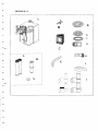
Installation of the Q-Gard purification pack (Figure 4)
(The Q-Gard is only used on Milli-Q systems equipped with a pack adapter)
WWJ-Q
Ac. Gr.8iaSpt.AI
1.
Raise the pack adapter (A) to its highest position. Remove the two protective plastic inserts (B) on the
pack adapter.
2.
Remove the two protective inserts on the Q-Gard pack (C). Wet the two O-rings with water.
3.
Push the Q-Gard so that the pack adapter metal rod (D) goes through the hole at the top of the Q-Gard.
- Lift the Q-Gard slightly and push the bottom of it into the small opening (E) on the system.
- At the upper pack adapter, push the pack completely in until secure.
4.
Lock the Q-Gard in place with the metal locking clip (F) on the end of the metal guide pin (D).
5.
Bring the adapter cap down to its lowest position (G) so that it covers the top of the Q-Gard.
Electrical connection of system
1.
Connect the power cord (Figure 2, B) to the Milli-Q (Figure 3,L). Connect the other end of the
power cord to an earth grounded power source.
2.
Check that the point of use gun trigger is in the upright position.
3.
Turn on the system electrical switch (figure 1, H) by putting it to position I.
4.
The serial number is displayed for 10 seconds. Note the serial number in the
table below.
Example:
\
GRAD1 ENT
VI . 0 0
SR . N = Z5AI.56K A 5 C
Type of Milli-Q system
""Note : Contact Millipore Technical Service when connecting a lowievel tank sensor to the Milli-Q system. As an
option, it is possible to get a "NO FEED WATER" message when there is no water in the reservoir.
Installation of the QUANTUM Ultrapure Cartridge (Figure 4)
Note : It is important to have the system switched on before installing the Quantum Ultrapure Cartridge.
1.
Open the blue door on the front of the Milli-Q by pressing the 2 latches (H) on the right side of the
door to open it.
2.
Remove the two protective inserts from the QUANTUM cartridge. Wet the two rubber O-rings on
the QUANTUM cartridge with water.
3.
Install the QUANTUM cartridge and push it in as far as it will go.
4.
Close the door. It is necessary to fully snap the latches (H) shut to hold the QUANTUM cartridge
inside.
Milli-Q - User Manual
Page 12 of 34
MIUt-Q
Ac. Gr. Bio.Syn.A10
Rinsing the Milli-Q for the first time
A 5 minute rinsing cycle "AIR PURGE" occurs automatically whenever new cartridges are installed in the Milli-Q
system.
1.
Open the feedwater isolation valve if there is one.
2.
The system will be waiting to begin the AIR PURGE cycle.
PREOPERATE
A IR PURGE :
5 mn
3.
Start the AIR PURGE by moving the point of use gun trigger down.
Direct all water from the point of use to a drain.
PRODUCT
AIR P U R G E :
4 mn
4.
At the end of 5 minutes the system will go into PRODUCT mode. Close
the point of use valve.
1 8 . 2MD cm
5.
If possible, leave the system in PRE-OPERATE mode overnight. This
helps to hydrate the ion exchange resin inside the cartridges.
6.
In PRE-OPERATE mode, purge the QUANTUM cartridge of any
trapped air by pushing the end of a small screwdriver into the small hole
located on the blue door (figure 4, K).
7.
Push the small screwdriver gently into the hole to purge out the trapped
[P~RJE o" P
E RATE
air.
Cleaning the A-10 measurement cell.
When a Milli-Q system is configured as an A-10 model, the system starts up by an automatic cleaning of the A-10
analysis cell. This cleaning lasts for 1 hour.
Connection of a printer with the system's RS 232 interface.
The Milli-Q system offers the possibility of sending information to a printer.
For further information, contact Millipore Technical Service.
Milli-Q - User Manual
Page 13 of 34
OPERATINGTHEMWrQ SYSTEM
MUI-Q
Ac. Q. Bio.Syn.AIO
Modes of operation
Your Milli-Q system has a number of operating modes which can be activated via the keypad. Other modes are
automatically activated by the microprocessor.
These different modes are displayed on the screen, and are described below :
Standard displays
OPERATING MODE
ACTION
STATUS OF SYSTEM
Press
the
OPERATE
/
STANDBY button while the
system is in PRE OPERATE
mode.
The system is in a STANDBY mode. While in
this mode, system operation is not possible.
Automatic recirculation does not occur in this
mode.
PRE OPERATE
Press
the
OPERATE
/
STANDBY button while the
system is in STANDBY mode.
In this mode the system will recirculate water for 5
minutes each hour.
During PRODUCT mode, the system displays the
product water resistivity compensated at 25 °C.
18.2 MQcm
Automatically occurs from PRE
OPERATE mode when point of
use trigger is moved forward;
This
is
referred
to
a
PRODUCTION mode.
25.5MQ-cm 18.6 °C
Automatically occurs from PRE
OPERATE mode when point of
use trigger is moved forward.
During PRODUCT mode, the system can display
the product water resistivity non temperature
compensated as well as the water temperature.
Press the MEASURE keypad
button when the system is in
PRE-OPERATE or PRODUCT
mode.
The product water temperature is displayed. For
systems with the A-10 option, the product water
TOC is also displayed.
In PRE OPERATE mode, press
the MENU button for 2 seconds
to view the counter.
The counter can be used to dispense water from
the system for a specific amount of time. This
time can be selected and changed with the keypad.
After the counter finishes, the system
automatically goes into STANDBY mode.
STANDBY
w
W
TEMP: 18.6 °C
TOC: 4ppb
"""
PROD. TIME SETUP
COUNTER: 9mn
->
FAST FLUSH
Automatic with Biocel and
Synthesis Milli-Q systems.
This is a rinsing of the ultrafiltration module and
lasts 30 seconds. It does not effect normal use of
the system.
~
TOC : 3 ppb
Occurs automatically.
Display of the last TOC measure or oxidation in
process.
Milli-Q - User Manual
Page 14 of 34
Additional displays
MIUI-Q
&. Bio.SynAlO
System maintenance messages
DISPLAYED MESSAGE
ACTION
SYSTEM STATUS
EXCH. CARTRIDGES
Occurs automatically.
See MAINTENANCE chapter for
further information
SERVICE LED blinking
The operational lifetime of the purification /
polisher cartridges has expired.
START SANIT.
Occurs automatically.
See MAINTENANCE chapter for
further information
SERVICE LED blinking
A cleaning of the ultrafiltration module is
necessary.
AIR PURGE
Automatic after installation of new
cartridges.
A 5 minutes air purge of the cartridge is in
progress.
EXCHANGE UV LAMP
Occurs automatically.
Call Millipore Technical Service
SERVICE LED blinking
The operational lifetime of the UV lamp of the
Milli-Q has expired.
EXCHANGE A10 UV
Occurs automatically.
Call Millipore Technical Service •
SERVICE LED blinking
The operational lifetime of the UV lamp inside
the A10' has expired.
Occurs automatically after installing
new purification / polisher pack(s).
It also can be started manually.
See the MAINTENANCE chapter
for further information.
SERVICE LED blinking
A cleaning cycle of the A-10 is in progress.
Duration is 60 minutes.
A10 CLEANING
59
Milli-Q - User Manual
Page 15 of 34
Alarm displays
DISPLAYS
STATUS of the SYSTEM
CARTRIDGE OUT
The Milli-Q has stopped operating because either the QUANTUM or Q-Gard
purification pack is loose.
See the QUANTUM and Q-Gard installation section for more information.
NO FEED WATER
The Milli-Q system is connected to a reservoir level sensor and has detected that the
reservoir is empty.
Wait until there is water in the reservoir.
SYSTEM ERROR #
Indication of a specific fault or malfunction with an internal component of the system.
See the TROUBLESHOOTING chapter for more information.
RS 232 ERROR
There is a problem with the RS 232 output.
See the TROUBLESHOOTING chapter for more information.
Service or maintenance needed for the A10 TOG accessory.
See the TROUBLESHOOTING chapter for more information.
~ * i l O ERROR #
-
NOTE:
'
.
'
-
•
*
The ALARM LED will blink while the above ALARM messages are displayed on
the LCD.
Milli-Q - User Manual
Page 16 of 34
Use of the Keypad
The keypad allows the user to activate the different operating modes or to review information about system
performance.
KEYPAD
ACTION
mi-Q
Ac. Q. BioSyn AIO
DISPLAY
STANDBY and PRE-OPERATE
Press the OPERATE / STANDBY keypad
button for at least 2 seconds to switch
between these two operating modes.
OPERATE/5TAN0BY MEASURE
CLEANING
MENU
STANDBY
STANDBY
/V
PRE-OPERATE
PRE-OPERATE
TOC
MEASURE
OPERATE/STANDS/ MEASURE
CIFANINS
MRf,
In PRODUCT or PRE-OPERATE mode,
22 . 6 ° C
Press MEASURE to display temperature TEMP :
IOC : 3 p p b
and last TOC value.
CLEANING
0PERATI3STANDBY MEAS'-RE
aEANING
MENU
The CLEANING function is described in the ROUTINE MAINTENANCE
chapter. This is for cleaning and sanitising the ultrafiltration module.
MENU FUNCTION
Programming a dispensing time period
Or-HWl/STANDBY MEASURE
OPERATE/STANDBY MEAS'jRt
In PRE-OPERATE mode only,
press MENU for at least 2 seconds.
CLF»'W5
aEANING
MENU
P&
PROD.TIME
COUNTER:
Select or change the COUNTER time by PROD.TI E
pressing the arrow keys. <|<! or [>[>
COUNTER:
SETUP
Omn
SETUP
I}mn
i
OPERATE/STANDBY MC»&U=>r
CLFAS'NG
MENU
Press OPERATE / STANDBY for at least 2
seconds to accept the COUNTER time.
PREOPERATE
Note: Moving the point of use trigger forward will initiate the COUNTER
and start to dispense water. The system will dispense water from the point
of use gun for the amount of time that the COUNTER is set to. When the
dispensing time is finished (COUNT = 0), the system will automatically go
to STANDBY mode. Move the Trigger back to the vertical position to go
to PRE OPERATE mode.
Milli-Q - User Manual
Page 17 of34
MUJ-Q
Ac G. Bio.Sjti.A10
Use of Keypad continued
KEYPAD
ACTION
DISPLAY
MENU function continued
Printer
In either PRE-OPERATE or PRODUCT
Press MENU for at least 2 seconds
OPERATE/STANDBY MfAf.u
PROD.TIME
COUNTER:
SETUP
0mn
%
OPERATE/STANDBY MEASURE
CLEANING
MENU
Press MENU
S ERVICE: PR INTER
PRESS "MEASURE"
I
OPERATE/STANDBY MEASURE
CLEANING
MENU
One press on the MEASURE button starts
printing
OPERATE/STANDBY MEASURE
CLEANING
MENU
Press MENU for at least 2 seconds,
display returns back to initial operating mode.
1 8 .2 nc
T O C : 3 ppb
Display the age of the UV lampfs*) and purification
cartridges
OPERATE/STANDBY MEASURE
•
•
OPERATE^STANDBY MEASURE
•
CLEANIKO
•
MENU
<
CLEANING
MENU
CLEANING
MENU
Press MENU twice,
the age of the UV lamp is shown
•
OPERATE/STANDBY MEASURE
•
OPERATE/STANDBY MEASURE
CLEANING
•
In either PRE-OPERATE or PRODUCT
Press MENU for at least 2 seconds
•
PROD.TIME
COUNTER:
SETUP
Ctmn
SERVICE:AGE
UV LAMP
6SDAYS
Press OPERATE/STANDBY once,
SERVICE:AGE
the age of the UV lamp in the A10 TOC module UV Al 0
'•> 8 D A Y S
is shown
MENU
Press OPERATE/STANDBY,
the age of the cartridge (s) is shown
SERVICE:AGE
CARTR.:
U8DAYS
MUl-Q
. Gt. Bio.S»n.A10
Use of Keypad continued
KEYPAD
ACTION
DISPLAY
MENU function continued
Printer
oFWATBsiANDBY MEASURE
CLEANING
MENU
|
in e i t h e r P R E - O P E R A T E or P R O D U C T
Press MENU for at least 2 seconds
PROD.TIME
COUNTER:
S ETUP
Omn
1
OPERATE/STANDBY MEASURE
CLEANINQ
MENU
SERVICE:PRINTER
PRESS "MEASURE"
Press MENU
I
0 P E R A T B S T A M 8 Y MEASURE
CLEANING
MENU
One press on the MEASURE button starts
printing
i
OPERATE/STANDBY MEASURE
CLEANING
MENU
'
Press MENU for at least 2 seconds,
display returns back to initial operating mode.
l 8 . 2 QC
T O C : 3 ppb
Display the age of the UV lamp(s^ and purification
cartridges
OPERATEffiTANOBY MEASURE
CLEANING
OPERATE/STANDBY MEASURE
CLEANING
MENU
In either PRE-OPERATE or PRODUCT
Press MENU for at least 2 seconds
Press MENU twice,
the age of the UV lamp is shown
PROD.TIME
COUNTER:
SETUP
dmn
SERVICE:AGE
UV LAMp
6SDAYS
I
OPERATE/STANDBY MEASURE
m,
TV A
m
CLEANING
m
MENU
m
OPERATBSTANOBY MEASURE
CLEANING
MENU
OPERATE/STANDBY MEASURE
CLEANING
MENU
Milli-Q - User Manual
Press OPERATE/STANDBY once,
SERVICE:AGE
the age of the UV lamp in the A10 TOC module UV Al 0
i> 8 D A Y S
is shown
Press OPERATE/STANDBY,
the age of the cartridge (s) is shown
Press MENU for at least 2 seconds,
display returns back to initial operating mode.
SERVICE:AGE
CARTR. : it 8DAYS
1 8 . 2 ac ra
T O C : j p !> b
Page 18 of 34
Use of Keypad continued
MOl-Q
Ac O. Bto.SjnA10
4CTIQN
DISPLAY
Cleaning the A10 module (Duration 1 hour)
The A-10 CLEANING mode is used to clean the oxidation
chamber of the A-10 and is described in detail in the
ROUTINE MAINTENANCE section
Choosing the display language
In either PRE OPERATE or PRODUCT mode
OPERATE/STANDBY MEASURE
CLEANING
Press MENU for 2 seconds
PROD.TIME
COUNTER:
SETUP
Omn
1
0PERATF./STAND8Y '•" '»c...Rt
r
-l I « M S ' -
MENU
Press MENU four times .
OPERATE/STANDBY MF-ASURc
CLEANING
Press the arrow keys to change
between different languages.
OPERATE/STANDBY MEASURE
SERVICE : OPT IONS
LANGUAGE : tNGL 1 Sil
CLEANING
Press MENU again to return to either
PRE OPERATE or PRODUCT mode.
MENU
SERVICE:OPT IONS
LANGUAGE : S PAN I S I
1 8 . 2MQ cm
TOC :
.'<
pp b
Choosing the unit of measurement
In either PRE OPERATE or PRODUCT
mode
OPERATBSIANDBY MEASURE
OPERATE/STANDBY MEASURE
CLEANING
Press MENU for 2 seconds
PROD. TI MB
COUNTER:
Press MENU four times
SERVICE :OPT IONS
LANGUAGE : t-NGL 1 S 5!
Press on OPERATE/STANDBY
SERVICE :OPT IONS
PROD . UN IT
MQcm
MENU
Cl£ANING
MENU
CLEANING
MENU
•
OPERATE/STANDBY MEASURE
OPERAIEraTANOBY MEASURE
CLEANING
MCNU
CLEANING
MENU
The arrow keys allow the choice of
M Qcm or \i Siemens cm "l as units
I
Milli-Q - User Manual
I
Press MENU again for 2 seconds
to return to the initial operating mode.
SETUP
omn
SERV I CE :OPT IONS
PROD . UNIT :
)i S
18.2 o c m
TOC : 3 pp b
Page 19 of 34
Using the keypad continued
KEYPAD
ACTION
DISPLAY
MUI-Q
Ac. a. Bio.Syn.A10
MENU function continued
Non temperature compensated resistivity display.
In either PRE OPERATE or PRODUCT mode
OPERATE/STANDBY MEASURE
CLEANING
MENU
Press MENU for 2 seconds
PROD.TIME
COUNTER:
SETUP
0mn
I
0PERATE/STAND3Y MEASURE
CLEANING
MENU
Press MENU four times
SERVICE :OPT IONS
I. A N G U A C H : HN(.,i. 1 S I
OPERATE/STANDBY MEASURE
CLFV.NG
MENU
OPERATBSTAN03Y MEASURE
CLEANING
MENU
CLEANING
MENU
•
OPERATE/STANDBY MEASURE
p
ress twice on
OPERATE/STANDBY
The arrow keys allow the choice of
a compensated or a non temperature
compensated resistivity display.
Press MENU again for 2 seconds
to return to the initial operating mode.
SERVICE :OPT IONS
T ° CORRECT ION: ON
SERVICE :OPT IONS
T°CORRECT ION:Of
I ••! . 4 M O c m
23.4-C
rOC : .' p p h
Purging the air out of the Ultrafiltration
Cartridge.
See Appendix 1, Purging the air from the UF
cartridge.
Milli-Q - User Manual
Page 20 of 34
Startup of the Milli-Q
MUIO
fie Gr. Bio.Syn.A10
The intermittent recirculation of water inside the Milli-Q has allowed the cartridge(s) to become fully hydrated.
Before installing the point of use filter (MILLIPAK 40), dispense about 2-3 litres of water from the system.
Installing the MILLIPAK 40 final filter (Figure 7)
-""
1.
Remove the venting cap (A) from the MILLIPAK 40.
2.
Screw the MILLIPAK 40 onto the point of use thread (B). Turn it a maximum of 2-3 times.
3.
Replace the venting cap but do not tighten it onto the MILLIPAK 40.
4.
Start to purge the MILLIPAK 40 by bringing the point of use gun trigger forward (C).
5.
When all of the air is purged from the MILLIPAK 40 by allowing water to run out of the vent,
tighten the venting cap (A).
6.
Close the point of use gun trigger (C) by moving it to the vertical position. The system will
automatically go into PRE-OPERATE mode.
Purpose of the LED on the point of use gun
When the point of use trigger is brought slightly forward, the Milli-Q system goes into a RECIRCULATION mode.
The green LED will flash when the water quality is not optimal. Once the green LED is lit steadily, the trigger can be
brought forward to dispense water from the point of use gun.
If the resistivity is below the setpoint, the green LED will blink continuously.
Milli-Q - User Manual
Page 21 of 34
MU1-Q
Ac Qr. BioSyfiAlO
MAINTENANCE
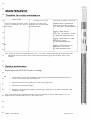
Timetable for routine maintenance
Every month
Note the operating parameters for the
system as indicated in the back of
this manual.
Annually (once a year)
Clean the screen filter in the
feedwater line. See ROUTINE
MAINTENANCE.
Following a message on the LCD
Display: EXCH. CARTRIDGES.
Replace the expendable cartridges.
See ROUTINE MAINTENANCE
Display: START SANIT.
Clean the Ultrafiltration module.
See ROUTINE MAINTENANCE
Display: EXCHANGE UV LAMP
Replace the UV lamp,,
See TROUBLESHOOTING
Display: EXCHANGE A10 UV
Replace the UV A10 lamp
See TROUBLESHOOTING
Note: When the product water flowrate becomes low (< 0.5 1/min.), change the MILLIPAK 40 final filter. If the
MILLIPAK 40 has only been in place a short time and becomes clogged, then check the quality of the
feedwater.
*- Routine maintenance
Replacing the QUANTUM Ultrapure Cartridge
1.
Put the Milli-Q system into STANDBY mode by pressing the OPERATE/STANDBY button for 2
seconds. Do not turn off the electrical power.
2.
Open the front blue door by pulling the 2 latches open (figure 4,H)
3.
Pull out the QUANTUM cartridge.
4.
Install the new QUANTUM cartridge by following the instructions in the "INSTALLATION AND
STARTUP" chapter.
Note: After replacing the QUANTUM cartridge, the system will begin a 5 minute AIR PURGE cycle. The
Synthesis and A-10 models will also have a TOC rinsing cycle.
Milli-Q - User Manual
Page 22 of 34
A: G.
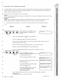
Sanitisation of the Ultrafiltration module
A regular sanitisation of the UF cartridge is necessary to obtain the best water quality and to have the maximum life
of the UF module. The Milli-Q system will periodically display every two weeks the message "START SANIT." to
inform you that a sanitisation is necessary.
There are two choices of sanitisation cycles in the software.
Cycle 1
This is a short sanitisation maintenance program. This allows the UF module to be sanitised at the start of an evening
and throughout that night.
This is a longer sanitisation maintenance program. This program allows for a more rigorous cleaning of the UF
module whenever flowrate is diminished from the system or the UF module is severely contaminated.
/\
Before starting a sanitisation, it is necessary to have more than 25 litres of feedwater available.
ACTION
KEYPAD
OPERATE/STANDBY MEASURE
Put the Milli-Q into STANDBY mode by
pressing OPERATE / STANDBY for 2 .
seconds
CLEANIN >
DISPLAY
STANDBY
i
Remove the MILLIPAK 40 from the point of use (figure 6)
I
Screw the adapter fitting (figure 2, G) onto the point of use.
•*•
Fit the 12 mm OD tubing (figure 2, F) onto the end of the barb fitting. Place the other end
of this tubing into a drain or sink.
4Remove the sanitisation port plug from the system. Keep it near the system
Introduce 3 grams of sodium hydroxide into the sanitisation port.
i
Screw the sanitisation port plug back onto the system. Check that it is secure.
OPERATBSTAMJBr MEASURE
CLEANING
MENU
Press CLEANING for 2 seconds
CLEAN ING : 1
(Pressing CLEANING again allows the choice o:
the longer sanitisation cycle).
i
Wait 10 seconds to validate the selection.
I
Bring the point of use trigger forward to begin
the sanitisation cycle.
CLEANING :1
OPEN THE VALVE
CLEAN ING
42 1 mn
I
At 400 minutes on the LCD, put the trigger
back to its upright position.
C L E A N I N G : 4 0 0mn
C L O S E THE V A L V E
I
At the end of the sanitisation cycle, the
system will automatically go into
PRE-OPERATE mode.
PRE O P E R A T E
i
Remove the tubing from the point of use. Remove the adapter fitting. Replace the
MILLIPAK 40.
The Milli-Q system is now ready for normal use.
Milli-Q - User Manual
Page 23 of 34
MUJ-Q
/>c Gc. Bio.Syn.A10
Replacing the Q-Gard Purification Pack (figure 4)
1.
Put the Milli-Q system into STANDBY mode by pressing OPERATE / STANDBY for 2 seconds.
Do not turn off the electrical power to the system.
2.
Bring the pack adapter (A) to its highest position.
Remove the metal retaining clip (F)
Remove the Q-Gard pack from the system.
3.
Install the new Q-Gard pack as described in the "INSTALLATION" chapter and in STARTUP.
Note: After replacing the Q-Gard pack, the Milli-Q will begin a purge cycle for 5 minutes followed by a TOC
rinsing cycle (60 minutes) for A10 models.
Replacing the MILLIPAK 40 (Figure 7)
The final filter MILLIPAK 40 should be changed whenever the product flowrate becomes too low (< 0.5 LPM) or
whenever the QUANTUM and Q-Gard cartridges are replaced. The lifetime of the MILLIPAK 40 is dependent
upon the quality of the feedwater and dependent upon the amount of water dispensed through the Milli-Q.
To change the MILLIPAK 40:
1.
Make sure that the point of use trigger (C) is in the closed (vertical) position.
2.
Remove the venting cap (A) from the MILLIPAK 40.
3.
Unscrew the MILLIPAK 40 from the female thread (B) on the point of use gun. Turn it
counterclockwise to unscrew it.
4.
Install the MILLIPAK 40 as described in the INSTALLATION chapter.
Cleaning the screen filter in the feedwater line (Figure 3)
1.
Close the valve on the feedwater line.
2.
Remove the feedwater tubing (C) from the fitting (F).
3.
Unscrew the fitting (E) form the feedwater pipe (D) and the other fitting (F).
4.
Clean the screen filter (G).
5.
Proceed in the opposite order to reinstall the screen filter.
Milli-Q - User Manual
Page 24 of 34
MUJ-Q
Ac Gr. BioSynAI
Cleaning the A10
Periodically, the detection cell in the A-10 needs to be cleaned of any built- up residual organic matter. If this buildup happens, then the displayed TOC values could be erratic or higher then previously seen.
To fix this, an autocleaning cycle is needed to oxidise any organic contaminants present in the A-10 detection cell.
To perform a cleaning cycle of the A-10, follow these instructions:
In PRE OPERATE mode
CWRMBSMNOSV MEASURE
OPERATBSTANOBY MEASURE
Ci MMV3
GLEANING
Press MENU for 2 seconds
PROD.TI E
COUNTER:
Press MENU 3 times
SERVICE :A 1 0
A 1 0 CLEAN ING
MENU
SETUP
Omn
MENU
Wait 5 seconds to validate the A-10 cycle.
After 60 mins. the system will
automatically return to its initial operating
mode.
(To interrupt the cleaning cycle)
OPERATBSTANOBY MEASURE
CLEANING
MENU
i
Press MENU for 2 seconds,
to return to the initial operating mode.
i S .
VOC
•'
P P
Note: It is possible to get water from the point of use valve during the A-10
CLEANING mode
Milli-Q - User Manual
Page 25 of 34
60
TROUBLESHOOTING
MUl-Q
Ac. &. 8o.Syi.AI
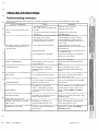
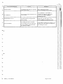
Troubleshooting messaaes
Whenever the SERVICE LED is blinking, a message is displayed on the screen which indicates the nature of the
service needed.
STATUS / PROBLEM
CAUSE
REMEDY
- No electrical power.
Check the source of power.
- The power cord is not plugged into Check the power cord.
There is no electrical power to the
the wall.
system.
- The system power fuse is defective Change the main power fuse.
or blown.
See APPENDIX 1
- The feedwater line valve is closed. Open the feedwater line valve.
- The pump does not work..
Contact Millipore Technical Service
- Inlet solenoid valve not opening..
Contact Millipore Technical Service
- Feedwater pressure is too low.
Verify that the feedwater pressure is at
least 0.1 Bar.
- Air is trapped in the final filter
The Milli-Q system is in PRODUCT
Purge air from the final filter. See
^ i o d e but does not produce any or
MAINTENANCE section., Replacing the
very little water.
MILLIPAK filter.
Clogged final filter.
See MAINTENANCE section, Replacing
the
MILLIPAK filter.
«*^
Air is trapped in the UF module.
Purge the UF cartridge. See Appendix 1,
Purging the UF cartridge.
EXCH. CARTRIDGES.
The Cartridge(s) are at the end of
their useful life.
Change the cartridge(s)
See the ROUTINE MAINTENANCE
chapter
CARTRIDGE OUT
The cartridge(s) are either not
installed properly or have been
removed.
Put the cartridge(s) back in place.
See the ROUTINE MAINTENANCE
chapter.
AIR PURGE
The cartridges were just replaced.
Wait for the 5 minute AIR PURGE to
finish before using water..
The error number corresponds to a
particular equipment error.
These error code numbers are listed later
in this manual.
The Milli-Q is connected to a
printer. A transmission error has
occurred between the Milli-Q and
the printer.
Press the OPERATE / STANDBY button
to reinitialise the system. If the error
persists, contact Millipore technical
service.
The Milli-Q is connected to a level
sensor in the feed reservoir.
Fill the reservoir with water before using
the Milli-Q again.
The Milli-Q is operating in a
preprogrammed software cycle.
Follow the displayed instructions and
wait for the program to end.
The limit of the UV lamp life has
been reached.
Replace the UV lamp. Call Millipore
Technical Service.
•MM*
-SYSTEM ERROR #
WM
RS232 ERROR.
NO FEED WATER
•M*
OPEN THE VALVE, FAST
FLUSH, SAN. CYCLE or CLOSE
THE VALVE
EXCHANGE UV LAMP
Milli-Q - User Manual
Page 26 of 34
MUIO
fie Gr. Bio.SynA
STATUS/PROBLEM
START SANIT.
A10 ERROR #
EXCHANGE A10 UV
A10 CLEANING
Milli-Q - User Manual
CAUSE
REMEDY
A cleaning cycle of the UF cartridge
needs to be started.
Start a cleaning procedure.
See the MAINTENANCE chapter.
An error has occurred with the A-10
TOC module.
Press OPERATE / STANDBY to
reinitialise the Milli-Q. If the error
persists, then contact Millipore
Technical Service.
The limit of the UV lamp life has
been reached.
Replace the UV lamp in the A-10.
Contact Millipore technical Service.
The Milli-Q has the A-10 inside.
The cartridges were just replaced or
an A-10 cleaning was started from
the SERVICE MENU.
Let the Milli-Q finish the 60 minute A-10
cleaning cycle. The Milli-Q can dispense
water during this mode.
Page 27 of 34
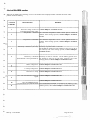
List of ALARM codes
MUI-Q
Q. Bio.Syn.Al
When the ALARM LED is flashing, an error code number will be displayed which indicates the nature of the
problem inside the Milli-Q.
SYSTEM
ERROR#
DESCRIPTION
1
The motor voltage is above its Contact Millipore Technical Service.
recommended operating value.
Temperature < minimum The measured temperature needs a short period of time to
stabilise. If the message persists, contact Millipore Technical
Service.
2
Temperature > maximum. The measured temperature needs a short period of time to
stabilise. If the message persists, contact Millipore Technical
Service.
3
4
5
REMEDY
Resistivity < minimum (off-scale). Resistivity of product water is off-scale.
Let the Milli-Q operate for a few minutes to force any air out of
the resistivity cell. If the message persists, Contact Millipore
Technical Service.
Resistivity > maximum Resistivity of water is off-scale. Let the Milli-Q operate for a
(measurement is not representative). few minutes to force any air out of the resistivity cell. If the
message persists, Contact Millipore Technical Service.
Motor voltage error. Contact Millipore Technical Service.
6
7
UV lamp voltage error. Contact Millipore Technical Service.
8
Defective UV lamp. Contact Millipore Technical Service.
9
Error with the electronics reference Contact Millipore Technical Service.
signal.
10
11
Contact Millipore Technical Service.
Error in EEPROM storage.
Communication error with the A-10. Press OPERATE/STANDBY to reinitialise the Milli-Q. If the
problem persists, then contact Millipore Technical Service.
Milli-Q - User Manual
Page 28 of 34
MUI-Q
Ac. Gt. Bio.Syti.AIO
A-10
ERROR#
DESCRIPTION
REMEDY
0
EEPROM saving error If the error persists, then contact Millipore Technical Service.
1
Error in analogue to digital If the error persists, then contact Millipore Technical Service.
conversion
The temperature exceeded acceptable limits during analysis.
Temperature range error. If the error persists, contact Millipore Technical Service.
2
3
4
5
The resistivity of the water in the The correlation between these two measurements has passed
A-10 is not accepted at the the allowed limits during the TOC measurement.
current temperature. If the error persists, then contact Millipore Technical Service.
The water temperature is below 5 °C. It is necessary that the
Temperature too low. temperature be above this value.
The water temperature is above 41 °C. It is necessary that the
Temperature too high. water temperature is below this value.
6
7
8
9
Milli-Q - User Manual
Conductivity too high Conductivity of the sample water exceeded the limit during
sampling.
Overheating The temperature exceeded 60 °C during oxidation.
If the error persists, then contact Millipore Technical Service.
Incomplete oxidation The sample oxidation was not completed in the allotted time.
If the error persists, then contact Millipore Technical Service.
Low oxidation rate The sample oxidation rate was abnormally low..
If the error persists, contact Millipore Technical Service.
Page 29 of 34
APPENDIX 1
MUI-Q
A; Q. BaSjnAlO
Interrupting the sanitisation cycle of a UF cartridge
If a sanitant chemical has been introduced into the Milli-Q, it is absolutely necessary to let the sanitisation cycle finish
in order to completely rinse the sanitant from the system.
If no sanitant has been introduced, then the sanitisation cycle can be cancelled by following these instructions.
SAN . CYCLE
OPERATBSJAN',9V ME*" .RE
CLEANING
VfN.
-I 2 Omn
STANDBY
Press CLEANING for 10 seconds
I
At the end of the sanitisation cycle, the MilliQ will go back to its initial mode of operation.
Purging trapped air from the UF cartridge.
In either PRE OPERATE or PRODUCT
OPERA US*AN09Y Hf'A'sJRE
Press MENU for 2 seconds
OFEfWBSIANDSY MEASURE
CLEANING
MENU
press MENU 5 times
PROD.TIME
COUNTER:
SETUP
S ERVICE : UF
AIR PURGE
Open the point of use valve to begin the air
purge cycle.
Dispense product water from the system to the
drain.
At the end of the air purge, the system will go
back into PRODUCT mode.
Close the point of use valve (trigger in vertical
position).
Interrupting the A-10 cleaning cvcle
If an A-10 cleaning cycle has been started from the MENU service mode, then it can be cancelled at any time by
pressing on the MENU button.
Milli-Q - User Manual
Page 30 of 34
MUI-Q
Ai Q.
~
Replacing the main electrical power fuse
1.
Put the system into STANDBY mode by pressing OPERATE / STANDBY for 2 seconds.
2.
Turn off the power switch (figure 1, G ) by putting it into the '0' position..
3.
Unplug the electrical power cord from the wall and from the system.
'-"
4.
Remove the fuse holder (figure 1,J).
•
5.
Remove the blown fuse and replace it with the spare fuse.
Note: Replace the spare fuse in the holder in the event that it may need to be used later.
6.
Replace the fuse holder and plug the power cord back in to the system and to the wall.
'**" Regulating the mobility of the point of use arm
The point of use arm can be adjusted in 2 locations. This adjustment is done by tightening the arm screw(s) with the
6 sided key (figure 2, K)
*—<
/\
Do not overtighten the arm screws. This may block movement of the arm, or damage the arm itself.
i
<•«*
«"•*
Recycling the reject water from the A-10 TOC
The reject water from the use of the A-10 can be recycled to a feed reservoir. Contact Millipore Technical Service
for more details.
w System is not operated for a long time
I
w
Keep the Milli-Q in PRE OPERATE mode when water is not needed. In this mode, the Milli-Q will operate all cycles
to keep the water quality optimum.
If the Milli-Q is to be shut down for a long time, contact Millipore Technical Service for further information.
Milli-Q - User Manual
Page 31 of 34
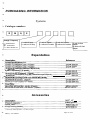
PURCHASING INFORMATION
Systems
Catalogue numbers
z
M
S
Q
\
Voltage / Frequency
230 V/50 Hz
= 120V/60Hz
7 = 100 V/50-60 Hz
V = with UV lamp
0 = without UV lamp
F = with UF module
0 = without UF module
T= with A10 module
0= without A10 module
Y= with Q-Gard
adapter
0= without Q-Gard
adapter
Expendables
pack
D2
_9y_
cartridgeJwithout^M|LUPAK)
9yMTi^iX(lonex}!_(1/pack)_
VXJVojati le_Or_g_ajijc_Carbon ftemqyal^O/pack)_
QTU M
QUANTUJ^EXJOjgane^O^/pack)
MILLIPAK 40 final filter, non-sterile, (1/pack)
MPGL 040 01
Accessories
?®te£e_19e_
2FMQOqOJPR~
Pnnter_cable
VVajlj^ounting bracket_
* Necessary if feed pressure > 0,3 bar (4.5 psi).
Milli-Q - User Manual
Page 32 of 34
- TECHMQAUNFQRMATION
w
Technical assistance
^_
For further information on Millipore products, please contact your nearest Millipore subsidiary.
w-
ADDRESS
Milli-Q - User Manual
Page 33 of 34
Warranty
Millipore Corporation ("Millipore") warrants the products manufactured by it against defects in materials and
workmanship when used in accordance with the applicable instructions for a period of one year from the date of
shipment of the products. MILLIPORE MAKES NO OTHER WARRANTY, EXPRESSED OR IMPLIED. THERE
IS NO WARRANTY OF MERCHANTABILITY OR FITNESS FOR A PARTICULAR PURPOSE.
The warranty provided herein and the data, specification and descriptions of Millipore products appearing in
Millipore's published catalogues and product literature may not be altered except by express written agreement
signed by an officer of Millipore. Representations, oral or written, which are inconsistent with this warranty or such
publications are not authorised and if given, should not be relied upon.
^h the event of a breach of the foregoing warranty, Millipore's sole obligation shall be to repair or replace, at its
option, any product or part thereof that proves defective in materials or workmanship within the warranty period,
provided the customer notifies Millipore promptly of any such defect. The exclusive remedy provided herein shall
not be deemed to have failed of its essential purpose so long as Millipore is willing to repair or replace any non
conforming Millipore product or part. Millipore shall not be liable for consequential damages resulting from
economic loss or property damages sustained by a customer from the use of its products.
However, in some states the purchaser may have rights under state law in addition to those provided by this warranty.
Milli-Q - User Manual
Page 34 of 34
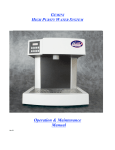
FIGURE N° 1
r^—i
B
G
M
D
FIGURE N° 2
D
B
E
F
H
L
G
M
I
N
,.--••;
-._
_.;
;__
FIGURE
—C
D
H
c
/
FIGURE 4
K
FIGURE N° 5
n
LJ
FIGURE 6
FIGURE 7
B