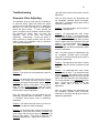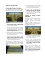
1
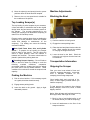
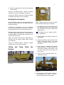
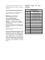
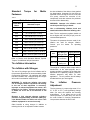
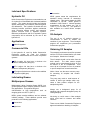
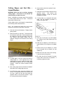
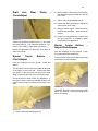
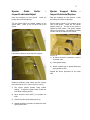
58348
JULY 2002
Service &
Operators
Manual
417 PULLED SCRAPER
Table of Contents
Foreword…………………………… 2
Safety Section
General Safety Information………. 3
Troubleshooting
Sequence Valve Adjusting……………. 23
Hydraulic Connections………………… 24
Crushing or Cutting Prevention….. 3
Nomenclature
Burn Prevention…………………… 3
Scraper Illustration………………………25
Lines, Tubes, and Hoses………… 3
Special Torques
General Section
Special Torque Specifications…………26
Specification and Model View…… 4
Serial Number Location…………... 4
Operation Section
Before Operating Machine……….. 5
Operating Techniques……………. 6
Top Loading Scraper(s)………….. 8
Parking the Machine……………… 8
Machine Adjustments…………….. 8
Transportation Adjustments……… 8
Maintenance Section
Torque Specifications…………….. 10
Tire Inflation Information…………. 11
Lubricating Specifications………... 12
Maintenance Interval Schedule….. 14
Cutting Edges and End Bits -……. 15
Inspect/Replace
Draft Arm Wear Plates - …………. 16
Check/Adjust
Ejector Carrier Rollers - …………..16
Check/Adjust
Ejector Guide Rollers - …………... 17
Check/Adjust
Ejector Support Rollers - ………… 17
Check/Adjust
Hitch – Lubricate/Inspect………….18
Router Bits – Inspect/Replace…… 18
Tire Inflation – Check……………...20
2
Foreword
Noble Construction Equipment products are a result of advanced
engineering, skilled manufacturing, and some of the finest materials metallurgical
science can select. Thousands of satisfying, economical working hours are built
into each machine.
For the owner to reach the maximum service from his or her scraper,
care must be exercised in its operation and maintenance.
The Operator &
Service Manual is written to give the operator essential information regarding the
day-to-day operation, lubrication, and adjustment of the scraper.
Some photos in this manual may show details or attachments that may
differ from your scraper.
Continuing improvement and advancement of product design by Noble
Construction Equipment may cause changes to your machine which may not be
included in this manual. Each manual is reviewed and updated, as required, to
update and include these changes in later editions.
If a question arises regarding your Noble Construction Equipment
scraper, or this manual, please consult your Noble Construction Equipment
dealer
for
the
latest
available
information.
3
General Safety Information
It is very important to read and understand all
safety precautions and warnings before
operating
and
performing
lubrication,
maintenance, and repair on this product.
Failures to observe basic safety rules or precautions
cause most accidents involving product operation,
maintenance, and repair.
Improper operation, lubrication, maintenance or
repair of this product can be dangerous and could
cause injury or even death.
WARNING:
It is important to read and
understand
the
operation,
lubrication,
maintenance, and repair information before
operating or performing any lubrication,
maintenance, or repair on this product.
The information, specifications, and illustrations in
this publication are on the basis of information
available at the time it was written.
The
specifications, torques, pressures, measurements,
adjustments, illustrations, and other items can
change at any time. These changes can affect the
service given to the product. Obtain the complete
and most current information before starting any job.
WARNING:
It is important to read and
understand the instructions and warnings in the
Service and Operators Manual before operating
the scrapers. Failure to do so could result in
injury or death. Contact any Noble Construction
Equipment dealer for replacement guides.
Proper care is the responsibility of the owner.
Crushing or Cutting Prevention
Protective glasses should be worn at all times
when servicing scraper(s) to avoid injury to
eyes, especially when striking a retainer pin.
Chips or other debris can fly off objects when
struck. Make sure no one can be injured by
flying debris before striking any object.
Burn Prevention
Personal injury can occur from hot hydraulic
oil and components. Do not contact hot oil or
components with bare skin.
Relieve all pressure before disconnecting
hydraulic lines, fittings, or related objects.
Tubes and Hoses
Do not bend, strike, or install bent or damaged
high pressure lines.
Repair tubes or hoses that are loose or
damaged.
Check tubes and hoses carefully. Do not use
your bare hand to check for leaks. Use a
board or cardboard to check for leaks.
Replace the parts if any of the following
conditions exist:
The end fittings are damaged, leaking, or
displaced.
The outer covering is chafed or cut.
The wire shield is exposed.
The outer covering is ballooning locally.
Provide adequate support for equipment and support
equipment properly when working beneath them.
Do not depend on hydraulic cylinders to hold up
machine. A piece of equipment can fall if a control is
moved, or if a hydraulic line breaks.
The flexible part of the hose is kinked or
crushed.
It is recommended to never adjust the scraper(s)
while the scraper(s) is moving unless otherwise
specified.
Make sure that all clamps and all guards are
installed correctly.
This will aid in the
prevention of vibrations and rubbing parts.
Stay clear of all rotating and moving parts.
Do not use a kinked or frayed wire rope cable. Wear
gloves when handling the wire rope cable.
The armoring is embedded in the outer
cover.
4
Product Information Section
Specifications and Model Views
Illustration 3
Noble Construction Equipment scraper serial
numbers are located on the left bowl side
(driver’s side) just to the right of the draft
frame trunnion.
Illustration 1
(1)
(2)
(3)
(4)
Draft Frame
Ejector
Apron
Bowl
Table 1
417 Pull Scraper (17 yd)
Overall Length 92.04 m (30.2 ft)
Overall Width
35.04 m (11.5 ft)
Overall Height
19.7 m (6.5 ft)
Weight
9072 kg (20,000 lbs)
Serial Number Location
Illustration 2
For quick reference, a space is provided below
to record scraper serial number.
Scraper serial number: 1710S__________
5
Operation Section
Before Operating Machine
and the bowl side should not exceed 5.0 ±
1.5 mm (0.20 ± 0.06 in) total, for both
sides. Make any necessary repairs.
Walk Around Inspection
To achieve maximum service life and for personal
safety, it is important to make a thorough walkaround inspection of the following scraper(s) areas
before operating the scraper(s).
Look around and under the machine for such items
as loose or missing bolts, trash build up, and
hydraulic fluid leaks. Inspect the condition and
inflation of the tires, condition of the bowl, hitch, draft
arms, and hydraulic components.
Illustration 6
3) Check hydraulic tubes and hoses for loose
clamps and mounting bolts. Check for
worn or frayed hoses.
Make any
necessary repairs.
4) Check all hydraulic tubes and hoses for
damage,
excessive
wear,
and
recommended torques. Do not use your
bare hands to check for leaks, use
cardboard or a board.
Illustration 4
1) Check tires for damage and proper inflation.
The proper inflation pressure for operating
scraper is 47 p.s.i.
Replace damaged or worn tubes and hoses.
Contact your Noble Construction Equipment
dealer for repair or replacement.
Illustration 7
Illustration 5
1) Check draft frame cross tube and goose neck for
cracks, damage, or distortion. Check for missing
or loose draft arm mounting bolts. Make any
necessary repairs.
2) Check draft arms for cracks or distortion. The
clearance between the draft arm wear plates
5) Check hitches, scraper to tractor and
scraper to scraper, for cracks, damage, or
distortion. Check for missing or loose
bolts. Make any necessary repairs.
6
3) Move ejector to the rear of the bowl and
raise apron to desired opening. If using
two scrapers move the ejector to the rear
of the bowl and raise the apron to desired
opening in both scrapers.
Illustration 8
6) Check bowl, ejector, and apron for cracks,
damage, or distortion. Make any necessary
repairs.
Note: The ejector should always be moved to
the rear of the bowl at the finish of dumping
the load. The chance of cylinder damage due
to bouncing will be reduced and it sets up
scraper for next loading pass.
Note: Apron throat opening depends on depth
of cut and type of material being loaded.
Operators will have to use their judgment on
proper throat opening.
4) Maintain tractor engine rpm. Start the cut.
5) Lower the bowl to an efficient cut depth for
loading the material.
Illustration 9
7) Check cutting edges, router bits, and tips for
wear, damage, or missing bolts. Make any
necessary repairs.
Operating Techniques
Loading
1) Load scraper in direction of the fill.
2) When approaching cut, reduce travel speed .
Downshift tractor to the proper speed for
material being loaded. The average speed for
loading is 5 m.p.h. Speeds may vary depending
on tractor being used and material being loaded.
Note: The cut should be shallow enough to
allow the machine to move at a constant
speed. If the cut is too deep, the tractor
engine may lug. Excessive tire slippage on
the tractor may also occur.
Decrease the cutting depth if the tractor
engine begins to lug or if the tires slip.
Use a lower speed if more torque is
required at the tractor tires.
6) Gauge the most efficient depth of cut by
the depth of the router bits. Use this
depth on successive passes. Keep cut
area as uniform as possible.
7) Pull the scraper(s) as straight as possible
during loading.
8) Do not overload the bowl(s). Overloading
the bowl(s) lowers machine efficiency.
9) When the bowl is full, lower apron and
raise the bowl simultaneously as you drive
forward.
Illustration 10
Note: For the best results, allow the apron to
be almost closed before raising the bowl.
Close the apron the rest of the way as the
bowl leaves the ground. This aids in keeping
dirt from piling up at the end of a cut.
7
5) If the scraper(s) start to creep while
traveling across a hillside, turn the tractor
to the downhill side. Likewise, turn the
tractor to the downhill side when the
scraper(s) is unstable. When you are
loaded and you are traveling across a
hillside, turning uphill should be done with
caution.
Illustration 11
10) If using two scrapers, fill front bowl first. As front
bowl raises, lower rear scraper ensuring that
they are not engage to the ground at the same
time.
Note: Try to start rear scraper cut at the point where
the first scraper was raised. This will provide a more
uniform cut area.
Note: To minimize down time due to weather, try to
maintain a grade which is suitable for good drainage
of water.
6) Maintain all haul roads. It is suggested
that the haul roads be the width of three
machines. Use a grader to maintain the
haul roads. A truck for applying water to
the road surface is also beneficial in some
conditions.
7) Try to avoid making deep ruts in the road.
Do not travel in the same track. Travel
next to the previous track in order to
reduce ruts.
Dumping and Spreading
Straddle Loading
Illustration 13
1) When you arrive at the fill, downshift the
tractor in order to maintain the proper
engine rpm.
Illustration 12
1) If possible, make successive passes leaving
short ridges 5 to 6 feet wide the entire width of
cut. On succeeding passes, pick up the ridges
at a depth below previous cuts. This will leave
other ridges, thus repeating the cycle.
2) Dump the material at the highest practical
travel speed.
3) Lower the bowl(s) to the desired spread
height
Traveling Loaded
Note: If using two scrapers, both scrapers can
be dumped at the same time.
1) Insure that the bowl(s) is raised high enough so
that it passes over obstacles.
4) At the start of the dump area, raise apron
and move ejector forward.
2) Always travel at a safe operating speed.
5) Finish dumping the load. Slowly raise the
bowl(s) in order to leave the dump area
smooth. Raise the bowl high enough so
that the bowl passes over obstacles.
3) When making turns, reduce the speed of the
tractor and scraper(s).
4) Loaded machines have the right away.
8
6) Move the ejector(s) and apron(s) back to precut
positions when the bowl has been emptied.
7) Return to the cut at a speed that is suitable for
the conditions of the job site.
Machine Adjustments
Blocking the Bowl
Top Loading Scraper(s)
The top loading of pulled scrapers by an excavator,
a front end loader, or a backhoe was not the original
design intent, but has become a common practice in
the industry. The success experienced by top
loading the scraper(s) has allowed the scraper(s) to
stand in for off-road dump trucks.
Extreme caution must be taken when top loading the
scraper(s) to avoid premature frame and cylinder
stress and damage to attachments on the
scraper(s). Top loading can cause the following
overload conditions:
Hitch, Draft Frame Arms, Axle, and Cylinder
Stress – To prepare for top loading, the scraper
must be lower to the ground. This will relieve the
shock or spike pressure when the material is
lowered into the bowl. The tractor should also be
placed in park and the parking brake set.
Exceeding Scraper Capacity – Do not fill above
level or struck full when top loading to avoid the
following
overload
conditions:
compaction
percentage inside the scraper bowl and the weight
per cubic yard of wet top loaded material. These
conditions can overload or exceed the scraper’s total
capacity.
Parking the Machine
1) Park on a level surface. If it is necessary to park
on a grade, block the wheels securely.
Illustration 14
1) Park the machine on level ground
2) Engage the tractor parking brake.
3) Raise the bowl and place blocks under the
bowl. Block material should be suitable
for carrying the weight of the bowl.
4) Lower the bowl to the block. Block the
bowl only to a height so that the bowl can
be worked on.
Transportation Information
Shipping the Scraper
Plan your travel route ahead of time and
check for overpass clearances. Insure that
there is adequate clearance for the
scraper(s) that is being transported.
Clear loading dock and truck bed of ice,
snow, or other slippery material before you
load the scraper(s).
2) Engage tractor parking brake.
3) Lower the bowl to the ground. Apply a slight
downward pressure.
To help prevent the scraper(s) from slipping
during transport, remove ice, snow, or other
slippery material.
Notice: Obey all state and local laws governing
the weight, width, and length of a load.
1) Block in front of and behind trailer or rail
car wheels before you load the scraper(s).
2) Lower all attachments to the floor of the
transport machine.
9
3) Block the scraper(s) tires. Secure the scraper(s)
with tie downs.
Travel at a moderate speed. Observe all speed
limitations when you are roading the scraper(s).
Consult your Noble Construction Equipment dealer
for shipping instructions for your scraper(s).
Roading the Scraper(s)
Illustration 16
Recommended tire pressures and speed limitations
should be obtained from your tire dealer before you
road the scraper(s).
Notice: Improper lifting or tie-downs can allow
load to shift and cause injury or damage.
Limitations for TON-kilometer per hour (TON-mile
per hour) must be obeyed. Consult your tire dealer
for the speed limit of the tires that are being used.
1) The weights and the instructions that are
specified below relate to the scrapers that
are manufactured by Noble Construction
Equipment Inc.
Schedule stops to allow the tires and components to
cool when traveling long distances. Stops should be
for approximately 30 minutes after every 40 km (25
miles) or after every hour.
Obtain the required licenses and authorization by
checking with the proper officials before roading
your scraper(s).
Travel at a moderate speed. Observe all speed
limitations when you road the machine.
Lifting and
Scraper
Tying
Down
the
The weight of the 417 scraper is 9072
kg (20,000 lbs).
2) Lifting brackets are located by decals on
the machine.
3) Proper rated cables and slings should be
used for lifting the scraper. The crane
should be in position to lift the scraper in a
level plane.
4) Each scraper is equipped with tie-down
shipping brackets. Two are located at the
front and are called out with decals. Use
the cross tube inside the rear frame for
rear tie down.
5) Lower the bowl completely before you
install the tie-downs.
Illustration 15
Illustration 17
6) If shipping two scrapers together, arrange
like ‘Illustrations 17’ above.
Bowl lift
cylinder stops have been provided by
10
Noble Construction Equipment and should be used.
Install tie-downs at several locations. Place blocks
around tires.
Standard Torque
Fasteners
for
Inch
Table 2
All of the laws that govern the actual load’s weight,
width, and length should be obeyed at all times.
Inch Nuts and Bolts
Thread Size
Inch
Standard Torques
1/4
12 ± 3 N·m (9 ± 2 lb ft)
5/16
25 ± 6 N·m (18± 4 lb ft)
3/8
47 ± 9 N·m (35 ± 7 lb ft)
Torque Specifications
7/16
70 ± 15 N·m (50 ± 11 lb ft)
General Torque Information
1/2
105 ± 20 N·m (75 ± 15 lb ft)
9/16
160 ± 30 N·m (120 ± 22 lb ft)
5/8
215 ± 40 N·m (160 ± 30 lb ft)
3/4
370 ± 50 N·m (275 ± 37 lb ft)
7/8
620 ± 80 N·m (460 ± 60 lb ft)
1
900 ± 100 N·m (660 ± 75 lb ft)
Exceptions to these torques are given in the Service
Manual, if necessary.
1 1/8
1300 ± 150 N·m (960 ± 110 lb ft)
1 1/4
1800 ± 200 N·m (1320 ± 150 lb ft)
Check to ensure that all components are in near new
condition before installation of any hardware. Bolts
and threads must not be worn or damaged. Threads
must be free of burrs or nicks. Hardware must be
free of rust and corrosion. Clean the hardware with
a non corrosive cleaner. Do not lubricate the
fastener threads except for the rust preventative.
The rust preventative should be applied by the
supplier of that component for purposes of shipping
and storage.
Other applications for lubricating
components may also be specified in the Service
Manual.
1 3/8
2400 ± 300 N·m (1780 ± 220 lb ft)
1 1/2
3100 ± 350 N·m (2280 ± 260 lb ft)
See your Noble Construction Equipment dealer for
shipping instructions for your scraper(s).
Maintenance Section
WARNING:
Possible injury, damage, or
malfunction can be caused by mismatched or
incorrect fasteners.
Caution should be taken to avoid mixing metric
dimensioned fasteners and inch dimensioned
fasteners.
11
Standard
Fasteners
Torque
for
Metric
Table 3
Metric Nuts and Bolts
Thread Size
Metric
Standard Torques
M6
12 ± 3 N·m (9 ± 2 lb ft)
M8
28 ± 7 N·m (21 ± 5 lb ft)
M10
55 ± 10 N·m (41 ± 7 lb ft)
M12
100 ± 20 N·m (75 ± 15 lb ft)
M14
160 ± 30 N·m (120 ± 22 lb ft)
M16
240 ± 40 N·m (175 ± 30 lb ft)
M20
460 ± 60 N·m (340 ± 44 lb ft)
M24
800 ± 100 N·m (590 ± 75 lb ft)
M30
1600 ± 200 N·m (1180 ± 150 lb ft)
M36
2700 ± 300 N·m (2000 ± 220 lb ft)
the slow oxidation of the rubber, slows gradual
tire deterioration (important for tires that are
expected to have a long service life of at least
four years), reduces the corrosion of rim
components, and also reduces the problems
that result from disassembly.
WARNING: Improper tire inflation could
result in personal injury or death.
Use a self-attaching inflation chuck and
stand behind the tread when inflating a tire.
Note: The tire equipment regulator should not
be set higher than 140 kPa (20 psi) over the
recommended pressure.
The same tire pressures that are used for air
inflation are used for nitrogen inflation.
Consult your tire dealer for operating
pressures.
Table 5
Refer to Service and Operators Manual “Special
Torques” for additional torque information
Tire Inflation Information
Tire Inflation with Nitrogen
The use of dry nitrogen gas for tire inflation and for
tire pressure adjustments is recommended by Noble
Construction Equipment. All machines with rubber
tires are included in this. Nitrogen being an inert gas
will not aid in combustion inside the tire.
WARNING: To avoid over inflation, the proper
use of nitrogen inflation equipment and training
in the use of that equipment is necessary.
Improper or misused equipment can cause a tire
blowout or rim failure. Serious personal injury
or death can occur due to tire blowout or rim
failure.
Because a fully charged nitrogen cylinder’s
pressure is approximately 15,000 kPa (2200 psi),
a tire blowout and/or rim failure can occur if the
inflation equipment is not used correctly.
Other benefits to using nitrogen in addition to
reducing the risk of an explosion include: lessens
Size
Ply Rating or Shipping Pressure
Strength Index
kPa
psi
29.5 x 25
28 Ply Bias
E-3 OTR Tire
324
47
29.5 x 25
22 Ply Bias E-2
Galaxy Tire
324
47
The weight of a ready-to-work scraper without
attachments, at the rated payload, and in
average operating conditions is the basis that
determines the operating inflation pressure.
Inflation pressures may differ for each
application. Tire air pressure should always
be obtained from your tire supplier.
Tire
Inflation
Adjustment
Pressure
The tire pressure in a warm shop area 18° to
21° C (65° to 70° F) will significantly change
when you move the machine into freezing
temperatures. If you inflate the tire to the
correct pressure in a warm shop, the tire will
be under inflated in freezing temperatures.
Low pressure shortens the life of a tire.
12
Lubricant Specifications
Hydraulic Oil
Noble Construction Equipment recommends the use
of a hydraulic oil formulated with a balanced additive
system. The system should include the following
agents: detergents, rust inhibitors, antiwear agents,
and defoamers. The hydraulic oil should offer the
following benefits: protection against mechanical
wear, protection against rusting, and protection
against corrosive wear in hydraulic systems.
Maximum performance and life of hydraulic system
components will be achieved by the use of this
hydraulic oil.
Applications
Hydraulic systems
Automotive
MPGL grease meets the requirements for
extended service intervals of automotive
chassis points. This product meets the NLGI
certification of “GC-LB”. MPGL grease is
available in NLGI Grade 2. Normal operating
temperatures for this product are –28° to
+149° C (-18° to +300° F). This product is
also available as a white lithium complex
grease.
Oil Analysis
The use of an oil analysis program is
recommended in order to monitor the
condition of your equipment. The oil analysis
program will compliment your preventative
maintenance program.
Commercial Oils
Obtaining Oil Samples
If the hydraulic oil used by Noble Construction
Equipment cannot be used, the following
commercial classifications can be used in hydraulic
systems.
The scraper(s) and tractor should be operated
until the oil is well circulated before you obtain
an oil sample. Obtain the oil sample.
CG-4 engine oils that have a minimum zinc
additive of 0.09 percent (900 ppm).
CF-4 engine oils that have a minimum zinc
additive of 0.09 percent (900 ppm).
CF engine oils that have a minimum zinc additive
of 0.09 percent (900 ppm).
Lubricating Grease
Multipurpose Greases
Multipurpose Lithium Complex Grease (MPGL) is a
general purpose lithium complex grease for mediumduty applications. This product has good
characteristics at high temperatures such as
dropping point over 260° C (500° F).
MPGL grease contains additives and an antiwear
inhibitor package. These additives provide extra
protection in the following applications.
Construction
Agriculture
The oil sample should not be taken from the
drain stream.
The drain stream sample
method can be contaminated by dirty oil from
the bottom of the oil compartment. Also,
never dip an oil sample from an oil container
or pour a sample from a used tractor filter.
Notice: Never use the same vacuum pump
for extracting oil samples and coolant
samples.
The pump may retain a small amount of
residue of either type sample which may
cause a false positive analysis for the
sample being taken.
Always use a designated pump for oil
sampling and a separate designated pump for
cooling sampling.
Not doing so could cause a false analysis
which could lead to customer and dealer
concerns.
There are two Noble Construction Equipment
approved methods to obtaining oil samples.
13
The following methods are listed in the order that is
preferred:
Use an in-line sampling valve for pressurized oil
systems.
Use a sampling gun that is inserted into the
sump.
The preferred method of sampling is the in-line
sampling valve. Contamination is less likely to occur
using this method. When you obtain the samples,
try to take the samples from the same location. This
allows the samples to be more representative of the
oil in the system.
The oil analysis is composed of four basic test:
Wear metal analysis
Infrared analysis for oil contamination
Test for contamination of the oil by fuel, by water,
and/or by antifreeze
Particle count for hydraulics
Keep in mind when taking the oil analysis, the
scraper(s) are using the same hydraulic oil that the
tractor is using.
Consult your Noble Construction Equipment Dealer
or tractor service manual for complete information
and assistance about the oil analysis program.
Sampling Interval
The oil samples should be taken as close to the
standard intervals as possible. You must establish a a
consistent trend of data to receive the full value from
taking oil analysis. Take evenly spaced samples to
establish a relevant data history.
14
Maintenance Interval Schedule
Note: All safety information, warnings, and
instructions must be read and understood before
you perform any operation or any maintenance
procedure.
Before each consecutive interval is performed, all of
the maintenance requirements from the previous
interval must also be performed.
When Required
Cutting Edges and End Bits – Inspect/Replace… 14
Draft Arm Wear Plates – Check/Adjust………….. 15
Ejector Carrier Rollers – Check/Adjust………….. 15
Router Bits – Inspect/Replace……………………. 18
Every 10 Service Hours or Daily
Hitch – Lubricate…………………………………… 17
Walk-Around Inspection……………………………21
Ejector Guide Rollers – Inspect/Lubricate/
Adjust………………………………………………...16
Every 50 Service Hours or Monthly
Tire Inflation – Check……………………………… 19
Every 250 Service Hours or Monthly
Ejector Support Rollers – Inspect/Lubricate/
Replace……………………………………………... 16
Hydraulic System Oil Sample – Obtain………….. 20
Wheel Bearing Check – Lubricate/Replace…….. 21
Every 2000 Service Hours or 1 Year
Ejector Carrier Rollers – Inspect/Pack/Replace…15
Ejector Guide Rollers – Inspect/Replace………...16
Ejector Support Rollers – Check/Replace………. 16
Hitch – Inspect………………………………………17
Hydraulic System Oil – Change………………….. 20
15
Cutting Edges and End Bits –
Inspect/Replace
6) New end bits should be installed if both
sides are worn.
WARNING: Block the bowl up before changing
cutting edges. If the bowl is not blocked up,
personal injury or death can occur.
7) Install the bolts and tighten the bolts to the
specified torque.
See Service and
Operators Manual, “Torque for Ground
Engaging Tool Bolts.”
Notice: Attempting to increase wear life by welding
on cutting edges should not be done. Premature
failure may result from this.
8) If cutting edge (1) is equipped with ripper
teeth, use the following procedure to
replace the ripper teeth.
Cutting edges need to be changed or rotated before
the mounting surface becomes worn.
Note: Any material that might fall on the worker
should be removed from the sides of the bowl.
1) Park the tractor and scraper(s). Engage tractor
parking brake.
2) Raise and block up the bowl. The bowl should
be blocked on both sides. Block material should
be suitable for carrying the weight of the bowl.
The blocked bowl height should only be
sufficient enough for the removal of the cutting
edges.
Illustration 19
9) Drive pin (5) through tip (4) and adapter
(3). Remove tip (4) and retainer (6) from
adapter (3).
10) Clean pin (5), adapter (3), and retainer (6).
Install retainer (6) in the groove in adapter
(3).
11) Install a new tip (4) on adapter (3). Install
pin (5) through tip (4), retainer (6), and
adapter (3).
12) Raise the bowl and remove the blocking.
Lower the bowl to the ground.
Illustration 18
3) If cutting edge (1) is worn, remove the bolts for
cutting edge (1). If the opposite side of the
cutting edge is not worn, rotate the cutting edge
and install the opposite side of the cutting edge
outward. Clean the contact surfaces before
installing.
4) New cutting edge sections should be installed if
both sides of the cutting edge are worn.
5) If end bits(2) are worn, remove the bolts for end
bits (2). If the opposite sides of the end bits are
not worn, rotate the end bits and install the
opposite sides of the end bits outward. Clean
the contact surfaces before installing.
13) The bolts should be checked for proper
torque after a few hours of operation. If
necessary, tighten the bolts.
16
Draft
Arm
Check/Adjust
Wear
Plates
–
2) Move eccentric roller shaft (1) to a position
that allows the ejector to pass over the top
of the floor.
3) Tighten roller shaft clamping bolt (2).
4) Repeat the above procedure to adjust the
other ejector carrier roller.
5) Start the tractor engine. Move the ejector
forward and backward. Stop the tractor
engine.
Illustration 20
Inspect the clearance between shim (1) and draft
arm wear plate (2). The clearance should be 3 ± 2
mm (0.118 ± 0.080 in). Add shims if necessary.
Repeat the procedure for draft arm wear plate on
other side of bowl.
Ejector
Carrier
Check/Adjust
Rollers
Park the scraper(s) on level ground.
bowl(s).
–
6) Inspect for drag between the ejector and
the top of the floor. If necessary, repeat
the procedure for adjustment.
Ejector Carrier Rollers
Inspect/Pack/Replace
–
Park the scraper(s) on level ground. Lower
the bowl(s) and close the apron(s).
The two carrier rollers are located at the base
of the ejector on the back side.
Lower the
The two ejector carrier rollers are located at the base
of the ejector on the back side. These rollers allow
the ejector to ride just above the floor of the bowl
without contacting the floor of the bowl at any point.
Check the ejector carrier rollers for adjustment. If
the ejector carrier rollers are adjusted properly, the
ejector does not come in contact with the floor of the
bowl.
Illustration 22
The debris should be removed from the roller
before it is checked. Pack the bearings of the
rollers as needed.
Illustration 21
1) Loosen roller shaft clamping bolt (2).
17
Ejector
Guide
Roller
Inspect/Lubricate/Adjust
Park the scraper(s) on level ground.
bowl(s) and close the apron(s).
–
Ejector Support Roller
Inspect/Lubricate/Replace
–
Lower the
Park the scraper(s) on level ground. Lower
the bowl(s) and close the apron(s).
The two guide rollers are located midway up the
ejector back. There is one on each side of the
ejector.
Ejector support rollers (1) are located at the
rear of the ejector. There are two ejector
support rollers (1). The rear of the ejector is
support by these rollers. The ejector support
rollers run in tracks (2). The tracks are located
on each side of the frame for the ejector.
Illustration 23
Lubricate one fitting on each side of the ejector.
Illustration 25
1) All debris should be removed in order to
check the roller.
2) Clean grease fitting.
3) Attach a grease gun to grease fitting and
apply grease to roller.
Repeat the above procedure for the other
side.
Illustration 24
Clearance between guide rollers and the scraper
bowl should be 0.75 to 1.50 mm (0.03 to 0.06 in).
1) The ejector should operate freely without
binding. To adjust the guide rollers, loosen the
roller shaft clamping bolt (2).
2) Move eccentric roller shaft (1) to position the
roller.
3) Tighten the roller shaft clamping bolt (2).
4) Repeat the above procedure to adjust the other
ejector guide roller.
18
Hitch – Lubricate
Hitch – Inspect
Hitch – Tractor to Scraper
Hitch – Tractor to Scraper
To lubricate the scraper ball that connects to the
tractor, locate the grease fitting on the drawbar
assembly. The fitting is located on the front right
side just under the lip of the drawbar.
Illustration 28
1) Inspect retainer plate for wear and cracks.
Replace if necessary
Illustration 26
1) Clean grease fitting.
2) Inspect retainer plate bolts and washers
for wear. Replace if necessary.
2) Attach a grease gun to grease fitting and apply
grease to ball.
Hitch – Scraper to Scraper
To lubricate the scraper ball that connects to the first
scraper, locate the grease fitting on the drawbar
assembly. The fitting is located on the front right
side just under the lip of the drawbar.
Illustration 29
1) Inspect drawbar at both ends, tractor pin
location and scraper ball location, for wear
and cracks. Replace if necessary.
Illustration 27
1) Clean grease fitting.
2) Attach a grease gun to grease fitting and apply
grease to ball.
Illustration 30
1) Inspect draft frame ball (1) for wear.
Replace if necessary.
19
2) Inspect draft frame ball for missing, worn, or
cracked stops (2).
Repair or replace if
necessary.
be suitable for carrying the weight of the
bowl. The blocked bowl height should
only be sufficient for the removal of the
router bits.
3) Shut off the tractor engine and engage the
tractor break.
Release the hydraulic
pressure on the hydraulic cylinders.
4) Rotating and installing the router bits on
the opposite side will allow for double
wear.
5) Remove the bolts and remove the router
bits.
Illustration 31
6) Clean the contact surfaces.
1) Inspect retainer plate for loose or missing bolts.
Replace if necessary.
7) New router bits should be installed if both
sides of the router bits are worn.
2) Inspect retainer plate for cracks and wear.
Replace if necessary.
8) Install the bolts for the router bits and
tighten the bolts to the specified torque.
See Service and Operators Manual,
“Torque for Ground Engaging Tool Bolts.”
Router Bits – Inspect/Replace
9) Raise the bowl. Remove the supporting
block. Lower the bowl to the ground.
10) The bolts should be checked for proper
torque after a few hours of operation. If
necessary, tighten the bolts.
Illustration 32
WARNING: Block the bowl up before changing
router bits. If the bowl is not blocked up,
personal injury or death can occur.
Router bits need to be changed or rotated before the
mounting surface becomes worn.
Note: Any material that might fall on the worker
should be removed from the bowl area.
If the router bits are worn or damaged, they need to
be replaced. There is one router bit on each side of
the bowl.
1) Park the scraper(s) on level ground.
2) Raise and block up the bowl. The bowl should
be blocked on both sides. Block material should
20
Tire Inflation – Check
WARNING: Improper tire inflation could result in
personal injury or death.
Improper or misused equipment can cause a tire
blowout or rim failure.
Use a self-inflating chuck and stand behind the
tread when inflating a tire.
To avoid over inflation, the proper use of
inflation equipment and training in the use of
that equipment is necessary.
Install tire on scraper or put tire in a restraining
device before inflating tire.
Hydraulic System Oil Sample –
Obtain
Refer to Service and Operators Manual, “Oil
Analysis” and Service and Operators Manual,
“Sampling Interval” for information that
pertains to obtaining a sample of the hydraulic
oil.
Hydraulic System Oil – Change
Notice: Take caution to ensure that all fluids
are contained during performance of
inspection, maintenance, testing, adjusting,
and repair of the product. Before opening any
compartments
or
disassembling
any
component containing fluids, plan ahead to
collect all fluids with suitable containers.
All fluids should be disposed of according to
local regulations and mandates.
Note: The scraper(s) must meet the following
conditions before you change the hydraulic
tank oil.
The scraper(s) and tractor must be level.
Illustration 33
Use a tire gauge to measure the pressure of each
tire. Nitrogen inflated tires can be checked with a
regular tire gauge.
Note: Nitrogen gas should be used to inflate scraper
tires in order to prevent the tire from exploding.
1) The valve stem should be between the 10
o’clock and 2 o’clock position.
2) Park the scraper(s) on level ground. Apply the
tractor parking brake. Lower the bowl(s). Shut
off the tractor engine.
3) The area around the valve stem should be clear
of all debris.
4) Remove the dust cover for the valve stem.
5) Use a tire gauge to measure the pressure of
each tire. Add nitrogen gas if pressure is low.
6) Reinstall the dust cover on the valve stem.
Insure that the tractor parking brake is set.
The hydraulic oil must be warm.
The bowl must be lowered.
Check tractor service manual for proper
instructions and techniques for draining
hydraulic tank.
Move ejector(s) to the rear of the scraper(s)
and close the apron(s) to ensure that the
majority of the dirty hydraulic oil is in the
tractor hydraulic tank.
Notice: If air has been allowed to enter
hydraulic hoses, tubes, or cylinders, bleed
hydraulic system by cycling all hydraulic
circuits several times before use. If there is a
failure in the hydraulic system, unsupported
raised equipment could suddenly lower,
causing serious personal injury or death.
21
Wheel
Bearing
Lubricate/Replace
Check
–
7) Remove wheel hub.
Remove outer
bearing (5 and 7) as soon as free of axle.
8) Remove inner bearing (4 and 6) from axle.
Wheel Bearing – Repacking
Wheel bearings should be packed either by hand or
by a mechanical bearing packer.
Either way
ensures that the lubricant is thoroughly worked into
the space between the rollers. Lubricant within the
bearing gives adequate lubrication, rather than that
surrounding it. Do not completely fill the wheel
bearing compartment but place a layer of grease 3
to 6 mm (0.125 to 0.25 in) thick on the hub and axle.
Take caution not to introduce dirt and grit into the
bearing.
Mechanical packers and lubricant
containers need to be inspected for foreign matter
before packing bearings.
Wheel Bearing – Replace
9) Wash and inspect bearings and seals.
Use new cup and cone if either cup or
cone of a set is damaged.
10) Pack bearing cones. Work grease in and
around rollers. Clean bearing recess in
wheel hub.
11) Install inner bearing (4 and 6) and seal (8).
Coat bearing cups with grease. Install
hub. Install outer bearing (5 and 7).
12) Install adjusting nut. Tighten until wheel
hub seizes. Back off ¼ turn. Wheel must
be free rolling without side play.
13) Install lock and locknut (3). Bend lock
tangs over outer nut. Pack cavity. Install
shim, gasket, and outer cover (2).
14) Install rim and tire. Recheck adjustment.
15) Remove blocking and lower scraper.
Walk – Around Inspection
WARNING: Personal injury can result from
hot oil and hot components. Do not allow
hot oil or components to contact skin.
Illustration 34
1) Park machine on level ground, lower scraper(s),
apply down pressure, set tractor parking brake,
raise and block rear of scraper, and stop tractor
engine.
2) Remove nuts from rim mounting bolts.
3) Remove rim and tire.
4) Remove axle bearing cover (2), shim, and
gasket by removing six bolts.
5) Straighten lock tangs.
6) Remove locknut (3) and lock washer.
Notice: Grease and oil that has accumulated
on the scraper(s) is a fire hazard. Any time a
significant quantity of oil is spilled on the
scraper(s) or at least every 1000 hours the
debris should be removed with steam cleaning
or high pressure water.
Note: Watch closely for leaks. If you observe
a leak, find the source of the leak and fix it. If
you suspect a leak or you observe a leak,
check the fluid levels more frequently.
22
5) Check the cutting edges, router bits, and
ripper teeth (3) for damage.
6) Check the hydraulic hoses (4) for leaks.
7) Check the tires (5) for any damage and
for proper inflation.
Replace any
missing valve caps.
8) Check all
scraper(s).
Illustration 35
Illustration 36
Illustration 37
1) Check the hitch and components (6 and7) for
cracks and loose or missing bolts.
2) Check the draft frame (2) for cracks, for damage,
and for distortion. Check draft frame cross-tube
for cracks or for damage.
3) Check the bowl and the ejector (1) for damage
and for distortion.
4) Check the tractor hydraulic oil level.
of
the
rollers
on
the
9) Grease all of the fittings that need to be
serviced on a daily basis.
23
Troubleshooting
Sequence Valve Adjusting
The sequence valve on driver side (lh) of machine is
to move the apron (gate) first before the ejector
(pusher) moves and sequence valve on ‘passenger’
side (rh) is to return the ejector to load position
before the apron lowers. If, when opening the
apron, the ejector moves forward or after the apron
has opened the ejector does not move, the
sequence valve on the driver side requires
adjustment. Alternatively, if when the ejector is
being returned to loading position and the apron
starts to close, the ‘passenger’ side (rh) sequence
valve requires adjustment.
valve with allen wrench held in place to secure
adjustment.
Note: On some tractors, the adjustment may
not completely eliminate ejector movement.
Less than 1” movement during apron raise is
satisfactory adjustment.
Problem: The apron lowers as the ejector is
returning to load position.
Solution: On ‘passenger-side’ valve, loosen
nut on bottom of valve. Turn screw with allen
wrench counter-clockwise until ejector returns
to load position and the apron does not move
until the ejector has fully returned to the load
position. Turn screw at least 1/8 turn counterclockwise past this point. Tighten nut on
bottom of valve with allen wrench held in place
to secure adjustment.
Note: On some tractors, the adjustment may
not completely eliminate apron movement.
Less than 5” movement during ejector return is
satisfactory adjustment.
Problem: The apron does not lower or lowers
very slowly after the ejector is returned to load
position.
Illustration 38
Problem: The ejector moves forward as the apron is
being raised.
Solution: On drive-side valve, loosen nut on bottom
of valve. Turn screw with allen wrench counterclockwise until apron raises and the ejector does not
move until the apron is fully raised. Turn screw at
least 1/8 turn counter-clockwise past this point.
Tighten nut on bottom of valve with allen wrench
held in place to secure adjustment.
Note: On some tractors, the adjustment may not
completely eliminate ejector movement. Less than
1” movement during apron raise is satisfactory
adjustment.
Problem: The ejector does not move or moves very
slowly after the apron is raised completely.
Solution: On drive-side valve, loosen nut on bottom of
valve. Turn screw with allen wrench clockwise until
apron raises and the ejector does not move until the
apron is fully raised. Turn screw at least 1/8 turn
clockwise past this point. Tighten nut on bottom of
Solution: On ‘passenger-side’ valve, loosen
nut on bottom of valve. Turn screw with allen
wrench clockwise until ejector returns to load
position and the apron does not move until the
ejector has fully returned to the load position.
Turn screw at least ¼ turn clockwise past this
point. Tighten nut on bottom of valve with
allen wrench held in place to secure
adjustment.
Note: On some tractors, the adjustment may
not completely eliminate apron movement.
Less than 5” movement during ejector return is
satisfactory adjustment.
24
Hydraulic Connections
Intermediate Scraper Hydraulics
The intermediate scraper is the scraper directly
behind the tractor if two scrapers are being pulled.
1) Circuits (5) and (6) control bowl movement
on the second scraper. Circuit (5) lowers
the bowl and circuit (6) raises the bowl.
2) Circuits (7) and (8) control apron and
ejector movement on the second scraper.
Circuit (7) raises the apron and then
moves the ejector forward. Circuit (8)
moves the ejector to the rear of the bowl
and then lowers the apron.
Trailing or
Hydraulics
Single
Scraper
The trailing scraper is the scraper behind the
intermediate scraper.
It plugs into the
hydraulics at the rear of the intermediate
scraper.
Illustration 39
1) Circuits (1) and (2) control the bowl movement
on the first scraper. Circuit (1) lowers the bowl
and circuit (2) raises the bowl.
If only one scraper is being pulled, the
hydraulics plug directly into the tractor as the
intermediate hydraulics would.
2) Circuits (3) and (4) control the apron and ejector
movement on the first scraper. Circuit (3) raises
the apron and then moves the ejector forward.
Circuit (4) moves the ejector to the rear of the
bowl and then lowers the apron.
3) Circuits (5) and (6) control bowl movement on
the second scraper. Circuit (5) lowers the bowl
and circuit (6) raises the bowl.
4) Circuits (7) and (8) control apron and ejector
movement on the second scraper. Circuit (7)
raises the apron and then moves the ejector
forward. Circuit (8) moves the ejector to the rear
of the bowl and then lowers the apron.
The hydraulics for the trailing scraper are routed
through the intermediate scraper. They come out at
the rear of the scraper and are connected by ORFS
fittings.
Illustration 41
1) Circuits (5) and (6) control bowl movement
on the scraper. Circuit (5) lowers the bowl
and circuit (6) raises the bowl.
2) Circuits (7) and (8) control apron and
ejector movement on the scraper. Circuit
(7) raises the apron and then moves the
ejector forward. Circuit (8) moves the
ejector to the rear of the bowl and then
lowers the apron.
Notice: If air has been allowed to enter
hydraulic hoses, tubes, or cylinders, bleed
hydraulic system by cycling all hydraulic
circuits several times before use. If there is a
failure in the hydraulic system, unsupported
raised equipment could suddenly lower,
causing serious personal injury or death.
Illustration 40
25
Nomenclature
Scraper Illustration
26
Special Torques