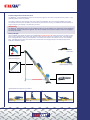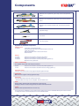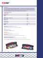
1
Table of contents
User manual
Product information and instructions
Basic principle
10
10
Components
Components of StaBFast® stabilisation system
Operation of individual components
11
11
Specifcations
Technical specifications
Maintenance and inspection
12
12
Stabilising
Points to watch during use
After use
Stabilising a vehicle lying on its side
Stabilising a vehicle that is lying on its roof
Stabilising a lorry cab
13
13
13
14
14
Illustrated instructions
For our illustrated instructions see our website: www.stabfast.nl
4
The manufacturer reserves the right to make changes to the design of the StaBFast® stabilisation system at any
time to reflect the latest technical developments and requirements.
4
The manufacturer accepts no liability for any unauthorised alteration of the StaBFast® stabilisation system.
Unauthorised alteration also invalidates the guarantee.
4
The manufacturer accepts no liability for any use of the stabilisation system for purposes other than those described
in these instructions. Such use also invalidates the guarantee.
4
The StaBFast® stabilisation system has been developed and manufactured in accordance with the valid
safety regulations.
4
The StaBFast® stabilisation system has a CE mark.
4
The StaBFast® stabilisation system is exclusively intended for use by fire brigades and related professional
emergency services.
Product information and instructions
The StaBFast® universal stabilisation system can be used on all types of cars, MPVs, minibuses and lorry cabins - in any
(unstable) position and on any surface.
The system makes use of the inherent mass of the vehicle to be stabilised. Once the vehicle is stabilised, the system
will not obstruct the rescue of casualties, and the vehicle is prevented from moving. The stabilised vehicle is therefore no
longer a danger to the casualty or the emergency services.
IMPORTANT
The StaBFast® stabilisation system is not suitable for lifting or moving weights. The straps must not be tightened
so far that the vehicle is lifted off the ground. The vehicle is stable as soon as the straps are taut. Do not tighten
the straps any further.
Basic principle
Place a stabiliser strut against the vehicle to be stabilised at an angle of 30° to 50°. Attach the hook on the strap to a firm
point as low as possible on the vehicle. Now tighten the strap using the ratchet on the stabiliser strut. This automatically
forms a triangular shape, causing a small proportion of the mass of the vehicle to be shifted to the foot of the stabiliser
strut. This distributes the mass of the vehicle over a broader area. This triangular shape is the basic principle of the
StaBFast® stabilisation system.
Hook blade
Tip fitted with
attachment lugs for
additional fixing point
Height-adjustable wedge
Telescopic arm lock
Strap clamped in spring
Tighten/release the ratchet in four positions
1.
Transport and lock
2.
Tighten
3.
Release
.
Neutral
Components
Stabiliser strut complete with green strap, hook and red protective
sleeve
Stabiliser strut complete with yellow strap, hook and red protective
sleeve
Stabiliser strut complete with blue strap, hook and red protective
sleeve
Adjustable wedge
Hook blade
Two carrying bags
Operation of individual components
Stabiliser strut
To extend
Lift the lock on the telescopic strut.
Extend the telescopic strut to the desired length from the top.
Lower the lock again.
Slide the telescopic strut in and out until it locks.
Check the lock.
Ratchet
To unlock
To tension
To release
Press the inner handle in and lift up one position.
Move the blue handle up and down (position 2).
Press the inner handle in and lift up one position (position 3).
Move the inner up and down.
NOTE ‘TO REALEASE’
This position only works if the strap is tensioned.
Neutral
To lock
Press the inner handle in and lift up one position (position 4).
Press the inner handle in and lower as far as it will go (position 1).
Adjustable wedge
Lift up top. Fold out the short or long support and place against the stop.
IMPORTANT
Make sure the support is firmly against the stop.
Hook blade
Unfold the black brace and hook it behind a firm point.
* Place the blade with the tip on the metal plate. Pull the handle round.
NOTE
During cutting, always make sure that the brace does not slip.
Enlarge the incision created using the flat end of the hook blade handle.*
*NOTE
Keep the blade protected with the red cover cap.
The purpose of the hookblade is only to make incisions. Moving the tip of the hookblade sideways will it cause to break.
To enlarge the incision use the flat (back) end of the hookblade handle.
IMPORTANT
The owner of the system must ensure that the StaBFast ® stabilisation system is only used by persons who
have read and understood these instructions for use. In order to ensure safe and effective use of the StaBFast ®
stabilisation system, it is important to regularly familiarise yourself with the use and operation of the system. All
valid health and safety regulations must be taken into account when using the StaBFast ® stabilisation system.
Keep these instructions for use together with the StaBFast® stabilisation system.
Technical specifcations
Stabiliser strut
Collapsed length:
Maximum extended length:
Weight:
Maximum load in longitudinal direction of strut (vertical):
107 cm
172 cm
9.5 kg
15 kN
Straps
Length of yellow and green strap:
Length of blue strap:
Maximum load:
500 cm
600 cm
50 kN
Hook
Maximum load:
25 kN
Adjustable wedge
Length x width:
Height adjustable:
Weight:
Maximum load:
60 x 10 cm
6 - 20 - 27 cm
5 kg
7.5 kN
Maintenance and inspection After every use
Whole system
Clean with a soft brush and a dry cloth. Inspect visually for damage.
Straps
Clean with a soft brush.
Inspect visually for damage.
In case of doubt, or if torn, replace strap.
Hook blade
Sharpen if necessary.
Maintenance and inspection Every three months
Whole system
Treat moving parts with silicon spray (including telescopic components of struts).
Maintenance and inspection Annually
Stabiliser struts, wedge and straps
Have checked in accordance with valid regulations for checking lifting and hoisting gear.
Replace all damaged and defective parts immediately with original parts. Treat corrosion immediately.
Points to watch during use
IMPORTANT
While freeing the casualty, check the stabilisers constantly. Check:
1. The tension of the straps. Tighten if necessary.
2. Ensure that the head of the strut is secure and does not move; if necessary secure it by use of a line from the eye
link to the vehicle.
3. That the foot of the stabiliser strut is not sagging or sliding.
4. That the adjustable wedge has not shifted.
5. The attachment of the hook to the vehicle.
After use
1. Loosen the straps using the ratchet (position 3).
IMPORTANT
If the vehicle is lying on its roof, loosen both straps simultaneously.
2.
3.
4.
5.
Collapse the telescopic struts.
Roll up the straps and clip under the spring on the strut.
Check that the set is complete when packing it away.
Clean and inspect the set as described under: “Maintenance and inspection After every use.”
Stabilising a vehicle lying on its side
1. Position stabiliser strut 1 with the green strap underneath the vehicle at the front (engine end). Extend the stabiliser
strut to its maximum length. Hook the hook into the vehicle as low as possible.
IMPORTANT
If the exhaust is hot, place a wooden board between it and the strap to protect the strap. Place the red protective
sleeve in front of any sharp objects. Using the ratchet, tighten the strap fully.
2. Position stabiliser strut 2 with the yellow strap at the front of the vehicle (bonnet end). Extend the stabiliser strut to its
maximum length. Using the hook blade, make an incision in the bonnet* as low down as possible. Hook the hook
into the incision. Slide the red protective sleeve in front of any sharp objects. Using the ratchet, tighten the strap fully.
NOTE
If possible, open the bonnet first and look for a firm point before making an incision with the hook.
3. Tighten the straps on both sides again. Check that both straps are taut.
IMPORTANT
Do not lift the vehicle.
4. Place stabiliser strut 3 with the blue strap underneath the vehicle at the back. Undo the strap at the bottom of the
stabiliser strut. Pass the loose strap through the roller in the tip of the adjustable wedge. Reattach the strap to the
bottom of the stabiliser strut.
IMPORTANT
Check that the strap is secure. Place the adjustable wedge under the vehicle at the back (boot end).
IMPORTANT
If the exhaust is hot, place a wooden board between it and the strap to protect the strap. Place the red protective
sleeve in front of any sharp objects. Tighten the strap until the vehicle is lifted a little way onto the adjustable
wedge.
5.
The vehicle is now stabilised.
Stabilising a vehicle that is lying on its roof
1. Place stabiliser strut 1 with the green strap at the back left-hand side of the vehicle. Extend the stabiliser strut to its
maximum length. Locate a firm point (in order of preference: (1) on the inside of the boot, (2) in the window groove
at the back of the vehicle, or (3) make an incision in the side of the vehicle with the hook blade). Insert the hook.
2. Position stabiliser strut 2 with the yellow strap at the back right-hand side of the vehicle. Extend the stabiliser strut
to its maximum length. Locate a firm point (in order of preference: inside the boot, in the window groove at the back
of the vehicle, or make an incision in the side of the vehicle with the hook blade). Insert the hook.
IMPORTANT POINT 1 & 2
Always fasten the hook to the bodywork of the vehicle. Place the red protective sleeve in front of any sharp
objects. Using the ratchet, tighten the strap fully.
3. Tension both sides again until the weight of the vehicle is resting on both stabiliser struts. Check that both straps are taut.
IMPORTANT
Do not lift the vehicle.
4. DANGER On a wet surface the vehicle may slide forwards during stabilisation and use of the system. Place a
wooden block at the front of the vehicle under the bonnet to prevent this from happening.
IMPORTANT
Check these blocks continuously during use of the system.
5. The vehicle is now stabilised.
Stabilising a lorry cab
NOTE
Before positioning the stabiliser struts, first decide where the working platform needs to be placed.
1. Place stabiliser strut 1 with the green strap on the left-hand side of the cab. Extend the stabiliser strut to
its maximum length. Locate an attachment point for the hook on the vehicle chassis (not the cab). Insert the hook.
Place the red protective sleeve in front of any sharp objects. Using the ratchet, tighten the strap fully.
2. Position stabiliser strut 2 with the yellow strap on the right-hand side of the cab. Extend the stabiliser strut to its
maximum length. Locate an attachment point for the hook on the vehicle chassis (not the cab). Insert the hook.
Place the red protective sleeve in front of any sharp objects. Using the ratchet, tighten the strap fully.
3. Position stabiliser strut 3 with the blue strap at the front of the cab. Extend the stabiliser strut to its maximum length.
Locate an attachment point for the hook on the vehicle chassis (not the cab). Insert the hook. Place the red
protective sleeve in front of any sharp objects. Using the ratchet, tighten the strap fully.
4. Tighten all straps until the cab is lifted out of its suspension slightly. The weight of the cab is now resting on the stabiliser struts.
5. The vehicle is now stabilised.
PT Hydraulics Australia Pty. Ltd.
19 Ricketts Rd, Mt. Waverley, Victoria
Phone: 03 9562 8800
Fax: 03 9562 8080
Email: [email protected]
www.pthydraulics.com.au